mikromill broaching€¦ · · 2016-04-12complete machining on cnc turning- and milling centres...
TRANSCRIPT
Dümmel®
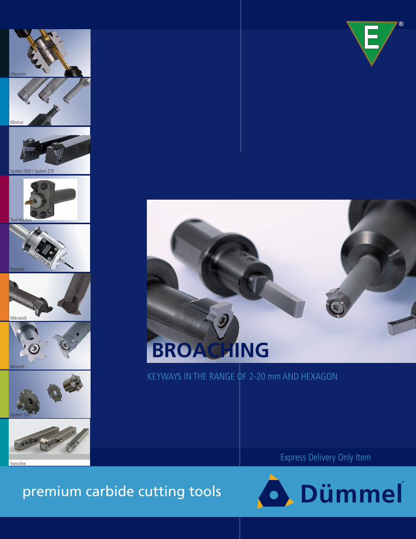
premium carbide cutting tools
KEYWAYS IN THE RANGE OF 2-20 mm AND HEXAGON
Express Delivery Only Item
E®
Minicut
System DED / System ZTP
Tool Holders
Mikromill
Minimill
System 500
Swissline
Rotaline
Ultramini
BROACHING
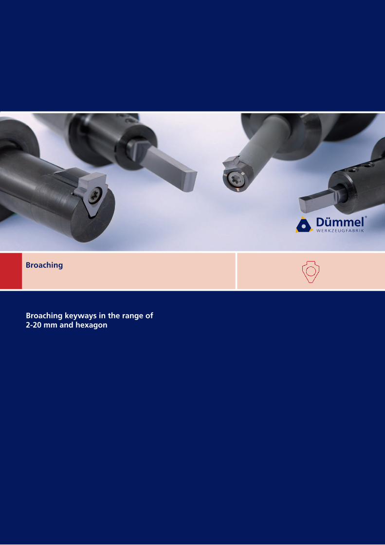
Broaching
Broaching keyways in the range of2-20 mm and hexagon
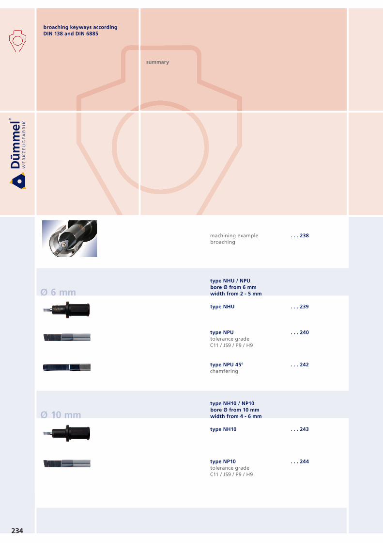
broaching keyways according
DIN 138 and DIN 6885
Ø 6 mm
Ø 10 mm
234
summary
machining example
broaching
type NHU / NPU
bore Ø from 6 mm
width from 2 - 5 mm
type NHU
type NPU
tolerance grade
C11 / JS9 / P9 / H9
type NPU 45°
chamfering
type NH10 / NP10
bore Ø from 10 mm
width from 4 - 6 mm
type NH10
type NP10
tolerance grade
C11 / JS9 / P9 / H9
. . . 238
. . . 239
. . . 240
. . . 242
. . . 243
. . . 244
L2
40 mm
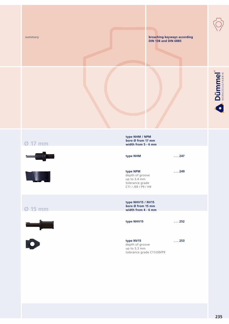
broaching keyways according
DIN 138 and DIN 6885
235
Ø 17 mm
Ø 15 mm
summary
type NHM / NPM
bore Ø from 17 mm
width from 5 - 6 mm
type NHM
type NPM
depth of groove
up to 3.4 mm
tolerance grade
C11 / JS9 / P9 / H9
type NHV15 / NV15
bore Ø from 15 mm
width from 4 - 6 mm
type NHV15
type NV15
depth of groove
up to 3.3 mm
tolerance grade C11/JS9/P9
. . . 247
. . . 249
. . . 252
. . . 253
236
summarybroaching keyways according
DIN 138 and DIN 6885
Ø 22 mm
type NHV / NPV
bore Ø from 22 mm
width from 6 - 24 mm
type NHV
type NPV
depth of groove
up to 8.5 mm
tolerance grade
C11 / JS9 / P9 / H9
type NPV 45°
chamfering
type NPU / NP10
for hexagon socket
. . . 255
. . . 257
. . . 259
. . . 260
237
set NPU
tolerance grade JS9
set NP10
tolerance grade JS9
set NPV
tolerance grade JS9
Technical instructions
general recommendation
cutting data
. . . 261
. . . 261
. . . 261
. . . 262
. . . 263
TIPP!
summary broaching keyways according
DIN 138 and DIN 6885
238
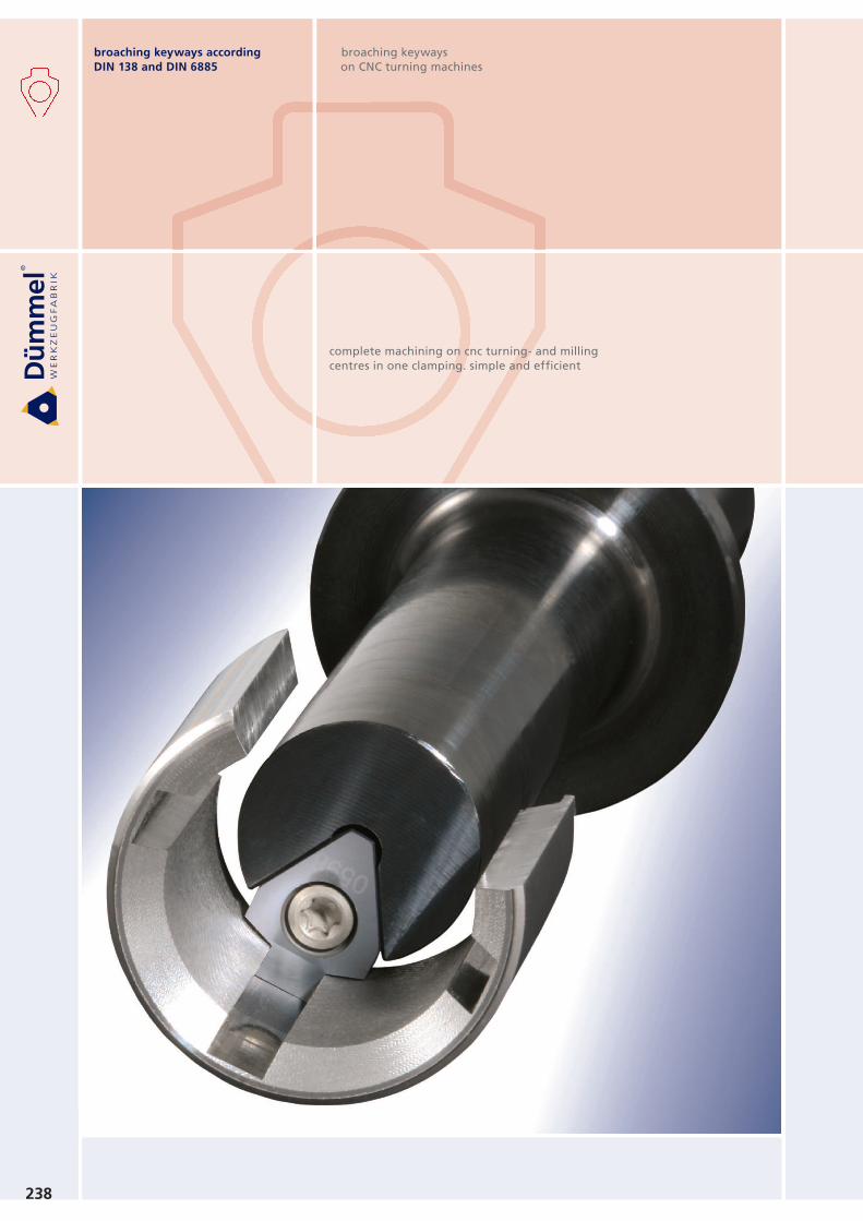
complete machining on cnc turning- and milling
centres in one clamping. simple and efficient
broaching keyways
on CNC turning machines
broaching keyways according
DIN 138 and DIN 6885

LL1 L2
h
dg
6
d2
d1
bore-Ø from 6 mm
239
Type NHU
toolholder
spare parts
screw 110.645 = M5x6
key 111.645 = M5x8
for NHU.0032.1
110.650 = M5x8
NHU.0020.1
NHU.0022.1
NHU.0025.1
NHU.0032.1
20
22
25
32
33
33
33
40
18
18
18
20
73
73
73
73
33
33
33
33
40
40
40
40
18
20
23
30
pa
rt n
um
be
r
dg6 d1 d2 L L1 L2 h
version
»Schwarzer 1«
»Schwarzer 2 in 1«
»EWS Slot« + »Benz LinA«
»Marchetti«
»WTO«
NHU.0012.1
NHU.0015.1
NHU.0016.1
NHU.MT16.1
NHU.WT16.1
time of delivery
max. 4 Wochen / weeksmax. 4 Wochen / weeksmax. 4 Wochen / weeksmax. 4 Wochen / weeksmax. 4 Wochen / weeks
part number
for broaching device
special toolholder for driven slotting tool
broaching keyways according
DIN 138 and DIN 6885
pa
rt n
um
be
r
B H r f L L1 use
ab
le f
rom
Ø
too
lho
lde
r ty
pe
L
L1
BH
+0
.05
Ø 7
.0 h
66
.30
+0
.05f
r r
240
NPU.0210.03.1
NPU.0310.03.1
NPU.0310.05.1
NPU.0410.05.1
NPU.0410.05.2
2.10
3.10
3.10
4.10
4.10
NHU
NHU
NHU
NHU
NHU
5.50
6.20
6.20
6.20
6.20
0.35
0.35
0.5
0.5
0.5
2.0
2.7
2.7
2.7
2.7
38
38
38
40
50
12.5
12.5
12.5
15
25
6.0
7.0
7.0
7.0
7.0
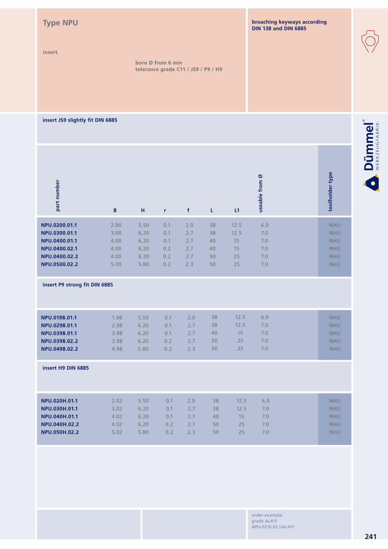
order-example:
grade AL41F
NPU.0210.03.1/AL41F
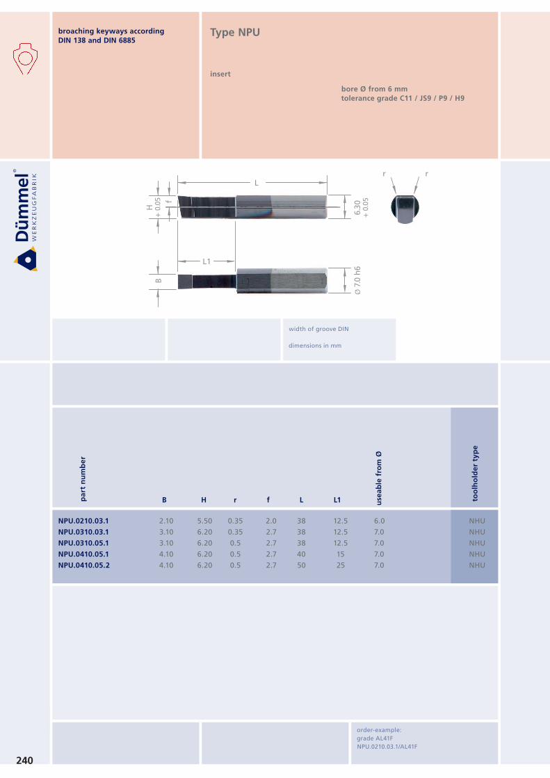
Type NPU
insert
bore Ø from 6 mm
tolerance grade C11 / JS9 / P9 / H9
width of groove DIN
dimensions in mm
broaching keyways according
DIN 138 and DIN 6885
pa
rt n
um
be
r
B H r f L L1 use
ab
le f
rom
Ø
too
lho
lde
r ty
pe
241
NPU.020H.01.1
NPU.030H.01.1
NPU.040H.01.1
NPU.040H.02.2
NPU.050H.02.2
2.02
3.02
4.02
4.02
5.02
NHU
NHU
NHU
NHU
NHU
5.50
6.20
6.20
6.20
5.80
0.1
0.1
0.1
0.2
0.2
2.0
2.7
2.7
2.7
2.3
38
38
40
50
50
12.5
12.5
15
25
25
6.0
7.0
7.0
7.0
7.0
NPU.0198.01.1
NPU.0298.01.1
NPU.0398.01.1
NPU.0398.02.2
NPU.0498.02.2
1.98
2.98
3.98
3.98
4.98
NHU
NHU
NHU
NHU
NHU
5.50
6.20
6.20
6.20
5.80
0.1
0.1
0.1
0.2
0.2
2.0
2.7
2.7
2.7
2.3
38
38
40
50
50
12.5
12.5
15
25
25
6.0
7.0
7.0
7.0
7.0
NPU.0200.01.1
NPU.0300.01.1
NPU.0400.01.1
NPU.0400.02.1
NPU.0400.02.2
NPU.0500.02.2
2.00
3.00
4.00
4.00
4.00
5.00
NHU
NHU
NHU
NHU
NHU
NHU
5.50
6.20
6.20
6.20
6.20
5.80
0.1
0.1
0.1
0.2
0.2
0.2
2.0
2.7
2.7
2.7
2.7
2.3
38
38
40
40
50
50
12.5
12.5
15
15
25
25
6.0
7.0
7.0
7.0
7.0
7.0
insert JS9 slightly fit DIN 6885
insert P9 strong fit DIN 6885
insert H9 DIN 6885
Type NPU
insert
bore Ø from 6 mm
tolerance grade C11 / JS9 / P9 / H9
order-example:
grade AL41F
NPU.0210.03.1/AL41F
broaching keyways according
DIN 138 and DIN 6885
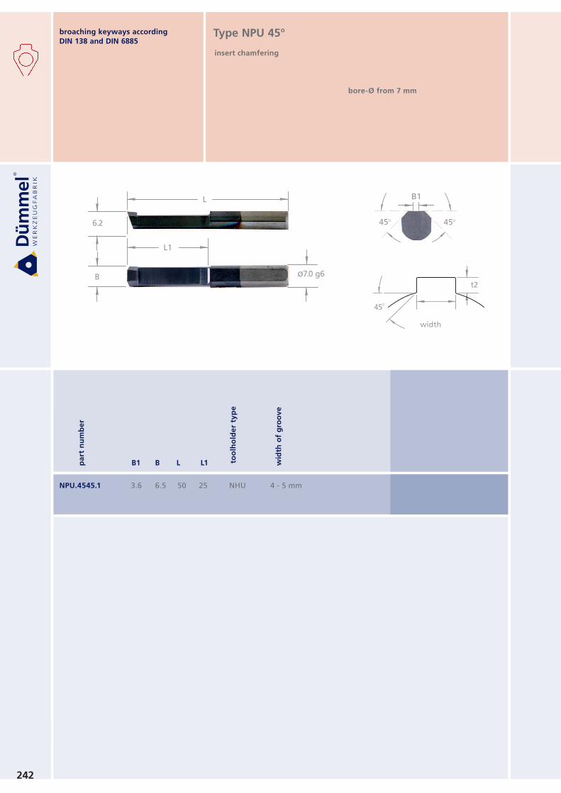
t2
45°
Nutbreite
width
L
L1
B
6.2
ø7.0 g6
B1
45°45°
242
pa
rt n
um
be
r
B1 B L L1
NPU.4545.1 3.6 6.5 50 25 NHU 4 - 5 mm
wid
th o
f g
roo
ve
Type NPU 45°
insert chamfering
bore-Ø from 7 mm
width
to
olh
old
er
typ
e
broaching keyways according
DIN 138 and DIN 6885
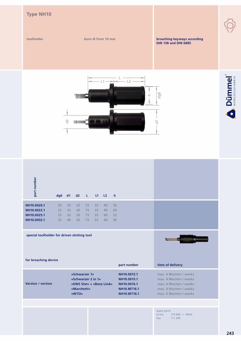
Version / version
»Schwarzer 1«
»Schwarzer 2 in 1«
»EWS Slot« + »Benz LinA«
»Marchetti«
»WTO«
NH10.0012.1
NH10.0015.1
NH10.0016.1
NH10.MT16.1
NH10.WT16.1
LL1 L2
h
dg
6
d2
d1
243
NH10.0020.1
NH10.0022.1
NH10.0025.1
NH10.0032.1
20
22
25
32
33
33
33
40
20
20
20
20
73
73
73
73
33
33
33
33
40
40
40
40
18
20
23
30
Type NH10
toolholder bore-Ø from 10 mm
pa
rt n
um
be
r
dg6 d1 d2 L L1 L2 h
spare parts
screw 110.660 = M6x6
key 111.300
time of delivery
max. 4 Wochen / weeksmax. 4 Wochen / weeksmax. 4 Wochen / weeksmax. 4 Wochen / weeksmax. 4 Wochen / weeks
part number
for broaching device
special toolholder for driven slotting tool
broaching keyways according
DIN 138 and DIN 6885

r rL
L1
BH
+0
.05
ø1
0.0
h6
9.2
0+
0.0
5f
244
NP10.410.05.2
NP10.410.05.3
NP10.510.05.2
NP10.510.05.3
4.10
4.10
5.10
5.10
NH10
NH10
NH10
NH10
9.0
9.0
9.0
9.0
0.5
0.5
0.5
0.5
4.0
4.0
4.0
4.0
50
66
50
66
25
41
25
41
10.0
10.0
10.0
10.0
Type NP10
insert
bore-Ø from 10 mm
tolerance grade C11 / JS9 / P9 / H9
pa
rt n
um
be
r
B H r f L L1 use
ab
le f
rom
Ø
too
lho
lde
r ty
pe
width of groove DIN
dimensions in mm
order-example:
grade AL41F
NP10.410.05.2/AL41F
broaching keyways according
DIN 138 and DIN 6885

245
NP10.040H.02.2
NP10.040H.02.3
NP10.050H.02.2
NP10.050H.02.3
NP10.060H.02.3
NH10
NH10
NH10
NH10
NH10
NP10.398.02.2
NP10.398.02.3
NP10.498.02.2
NP10.498.02.3
NP10.598.02.3
3.98
3.98
4.98
4.98
5.98
4.02
4.02
5.02
5.02
6.02
9.0
9.0
9.0
9.0
8.5
9.0
9.0
9.0
9.0
8.5
0.2
0.2
0.2
0.2
0.2
0.2
0.2
0.2
0.2
0.2
4.0
4.0
4.0
4.0
3.5
4.0
4.0
4.0
4.0
3.5
50
66
50
66
66
50
66
50
66
66
25
41
25
41
41
25
41
25
41
41
10.0
10.0
10.0
10.0
10.0
10.0
10.0
10.0
10.0
10.0
insert JS9 slightly fit DIN 6885
NP10.400.02.2
NP10.400.02.3
NP10.500.02.2
NP10.500.02.3
NP10.600.02.3
4.00
4.00
5.00
5.00
6.00
NH10
NH10
NH10
NH10
NH10
9.0
9.0
9.0
9.0
8.5
0.2
0.2
0.2
0.2
0.2
4.0
4.0
4.0
4.0
3.5
50
66
50
66
66
25
41
25
41
41
10.0
10.0
10.0
10.0
10.0
order-example:
grade AL41F
NP10.410.05.2/AL41F
insert P9 strong fit DIN 6885
insert H9 DIN 6885
Type NP10
insert
bore-Ø from 10 mm
tolerance grade C11 / JS9 / P9 / H9
NH10
NH10
NH10
NH10
NH10
broaching keyways according
DIN 138 and DIN 6885
pa
rt n
um
be
r
B H r f L L1 use
ab
le f
rom
Ø
too
lho
lde
r ty
pe
L1
L2
ød
g6
ø 3
5m
m
SW
40 mmø D2
247
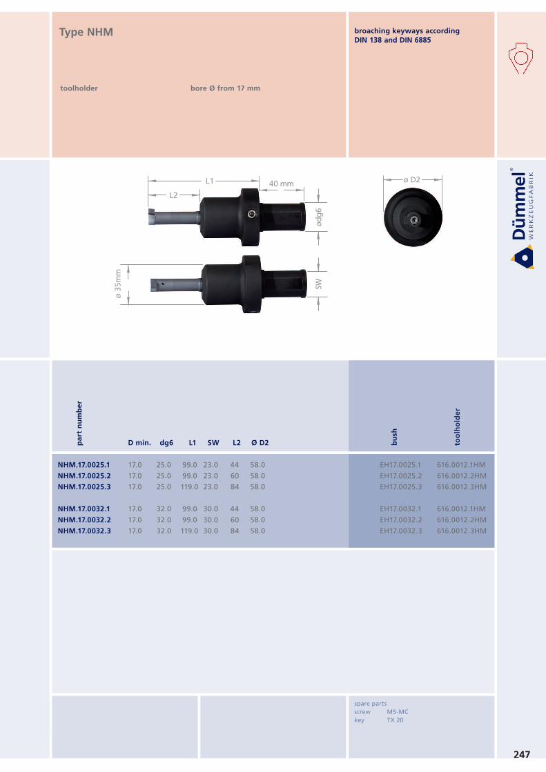
NHM.17.0025.1
NHM.17.0025.2
NHM.17.0025.3
NHM.17.0032.1
NHM.17.0032.2
NHM.17.0032.3
17.0
17.0
17.0
17.0
17.0
17.0
25.0
25.0
25.0
32.0
32.0
32.0
99.0
99.0
119.0
99.0
99.0
119.0
23.0
23.0
23.0
30.0
30.0
30.0
44
60
84
44
60
84
58.0
58.0
58.0
58.0
58.0
58.0
EH17.0025.1
EH17.0025.2
EH17.0025.3
EH17.0032.1
EH17.0032.2
EH17.0032.3
bu
sh
616.0012.1HM
616.0012.2HM
616.0012.3HM
616.0012.1HM
616.0012.2HM
616.0012.3HM
too
lho
lde
r
pa
rt n
um
be
r
D min. dg6 L1 SW L2 Ø D2
spare parts
screw M5-MC
key TX 20
Type NHM
toolholder bore Ø from 17 mm
broaching keyways according
DIN 138 and DIN 6885
248
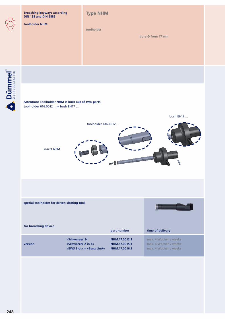
Attention! Toolholder NHM is built out of two-parts.
toolholder 616.0012 ... + bush EH17 ...
toolholder 616.0012 ...
insert NPM
bush EH17 ...
Type NHM
toolholder
bore Ø from 17 mm
version
»Schwarzer 1«
»Schwarzer 2 in 1«
»EWS Slot« + »Benz LinA«
NHM.17.0012.1
NHM.17.0015.1
NHM.17.0016.1
time of delivery
max. 4 Wochen / weeksmax. 4 Wochen / weeksmax. 4 Wochen / weeks
part number
for broaching device
special toolholder for driven slotting tool
broaching keyways according
DIN 138 and DIN 6885
toolholder NHM
f
r r
t max.
s B
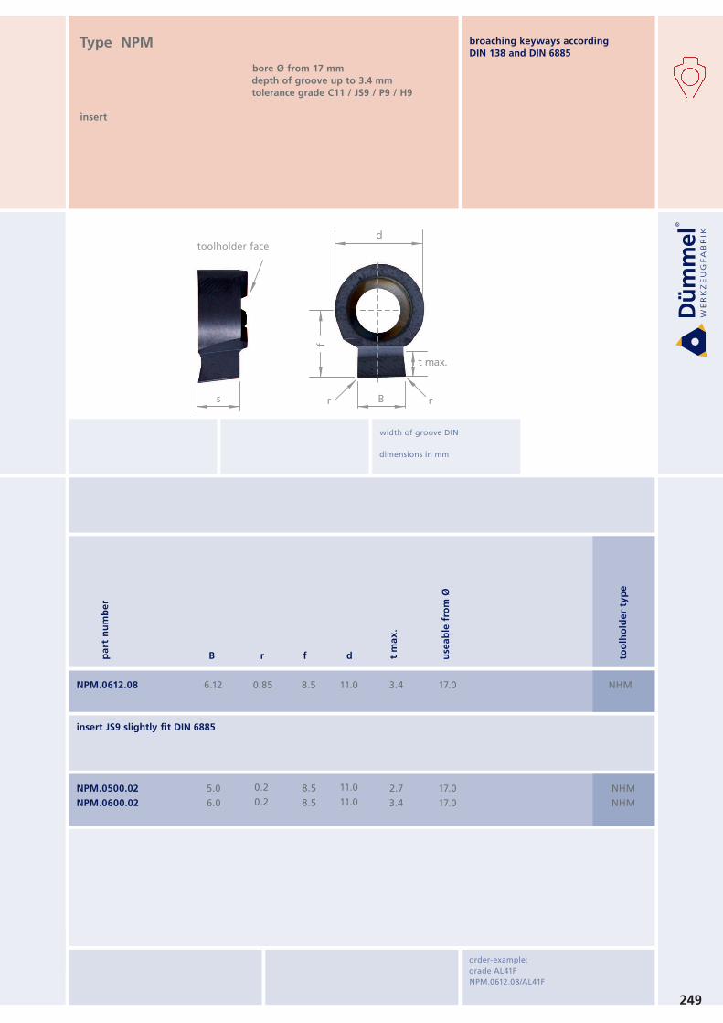
dKlemmhalter Stirnseite
toolholder face
249
pa
rt n
um
be
r
B r f d use
ab
le f
rom
Ø
too
lho
lde
r ty
pe
width of groove DIN
dimensions in mm
insert JS9 slightly fit DIN 6885
NPM.0612.08 6.12 NHM0.85 8.5 11.0 3.4 17.0
NPM.0500.02
NPM.0600.02
NHM
NHM
5.0
6.0
0.2
0.2
8.5
8.5
11.0
11.0
2.7
3.4
17.0
17.0
Type NPM
insert
bore Ø from 17 mm
depth of groove up to 3.4 mm tolerance grade C11 / JS9 / P9 / H9
order-example:
grade AL41F
NPM.0612.08/AL41F
toolholder face
t m
ax
.
broaching keyways according
DIN 138 and DIN 6885
NHM
NHM
4.98
5.98
5.02
6.02
0.2
0.2
0.2
0.2
8.5
8.5
8.5
8.5
11.0
11.0
11.0
11.0
2.7
3.4
2.7
3.4
17.0
17.0
17.0
17.0
NPM.050H.02
NPM.060H.02
NHM
NHM
NPM.0498.02
NPM.0598.02
250
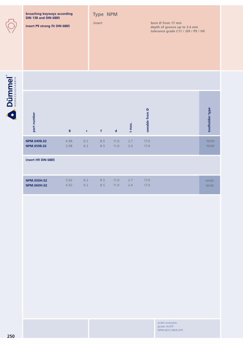
insert H9 DIN 6885
order-example:
grade AL41F
NPM.0612.08/AL41F
Type NPM
insert bore Ø from 17 mm
depth of groove up to 3.4 mm tolerance grade C11 / JS9 / P9 / H9
broaching keyways according
DIN 138 and DIN 6885
insert P9 strong fit DIN 6885
pa
rt n
um
be
r
B r f d use
ab
le f
rom
Ø
too
lho
lde
r ty
pe
t m
ax
.
Version / version
»Schwarzer 1«
»Schwarzer 2 in 1«
»EWS Slot« + »Benz LinA«
»Marchetti«
»WTO«
NHV.15.0012.1
NHV.15.0015.1
NHV.15.0016.1
NHV.15.MT16.1
NHV.15.WT16.1
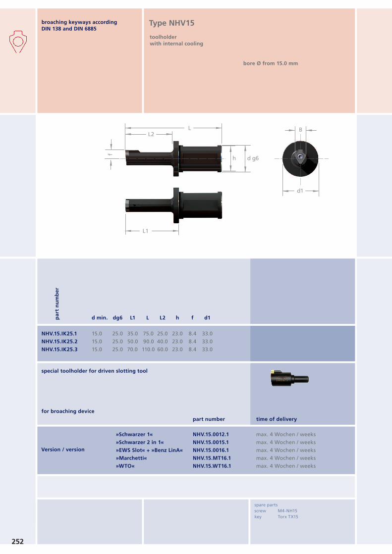
L
L1
L2
h d g6
f
B
d1
NHV.15.IK25.1
NHV.15.IK25.2
NHV.15.IK25.3
15.0
15.0
15.0
25.0
25.0
25.0
35.0
50.0
70.0
75.0
90.0
110.0
25.0
40.0
60.0
23.0
23.0
23.0
8.4
8.4
8.4
33.0
33.0
33.0
pa
rt n
um
be
r
d min. dg6 L1 L L2 h f d1
spare parts
screw M4-NH15
key Torx TX15
broaching keyways according
DIN 138 and DIN 6885Type NHV15
toolholder
with internal cooling
bore Ø from 15.0 mm
time of delivery
max. 4 Wochen / weeksmax. 4 Wochen / weeksmax. 4 Wochen / weeksmax. 4 Wochen / weeksmax. 4 Wochen / weeks
part number
for broaching device
special toolholder for driven slotting tool
252
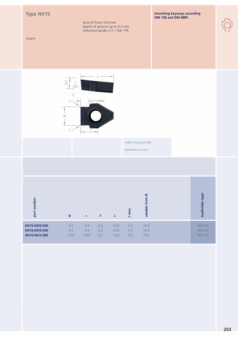
5°
L
5.3
B
r
r
f
t max.
253
broaching keyways according
DIN 138 and DIN 6885
NV15.0410.050
NV15.0510.050
NV15.0612.085
4.1
5.1
6.12
NHV.15
NHV.15
NHV.15
0.5
0.5
0.85
6.5
6.5
6.5
13.0
13.0
13.0
2.2
2.5
2.6
15.0
15.0
15.0
Type NV15
insert
bore Ø from 15.0 mm
depth of groove up to 3.3 mm tolerance grade C11 / JS9 / P9
width of groove DIN
dimensions in mm
pa
rt n
um
be
r
B r f L use
ab
le f
rom
Ø
too
lho
lde
r ty
pe
t m
ax
.
254
broaching keyways according
DIN 138 and DIN 6885
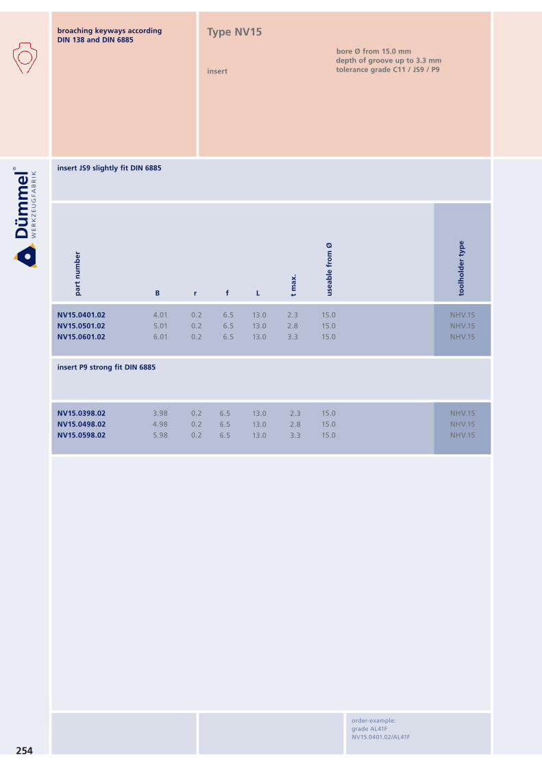
insert JS9 slightly fit DIN 6885
insert P9 strong fit DIN 6885
order-example:
grade AL41F
NV15.0401.02/AL41F
Type NV15
insert
bore Ø from 15.0 mm
depth of groove up to 3.3 mm tolerance grade C11 / JS9 / P9
NV15.0401.02
NV15.0501.02
NV15.0601.02
4.01
5.01
6.01
NHV.15
NHV.15
NHV.15
0.2
0.2
0.2
6.5
6.5
6.5
13.0
13.0
13.0
2.3
2.8
3.3
15.0
15.0
15.0
NV15.0398.02
NV15.0498.02
NV15.0598.02
3.98
4.98
5.98
NHV.15
NHV.15
NHV.15
0.2
0.2
0.2
6.5
6.5
6.5
13.0
13.0
13.0
2.3
2.8
3.3
15.0
15.0
15.0
pa
rt n
um
be
r
B r f L use
ab
le f
rom
Ø
too
lho
lde
r ty
pe
t m
ax
.
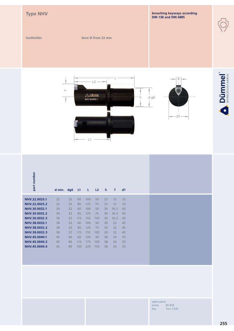
L
L1
L2
h d g6
f
B
d1
255
NHV.22.0025.1
NHV.22.0025.2
NHV.30.0032.1
NHV.30.0032.2
NHV.30.0032.3
NHV.38.0032.1
NHV.38.0032.2
NHV.38.0032.3
NHV.45.0040.1
NHV.45.0040.3
NHV.45.0040.4
22
22
30
30
30
38
38
38
45
45
45
25
25
32
32
32
32
32
32
40
40
40
60
85
60
85
115
60
85
115
60
115
165
100
125
100
125
155
100
125
155
120
175
225
50
75
50
75
105
50
75
105
50
105
155
23
23
30
30
30
30
30
30
38
38
38
12
12
16.5
16.5
16.5
22
22
22
24
24
24
33
33
45
45
45
45
45
45
55
55
55
Type NHV
toolholder bore Ø from 22 mm
pa
rt n
um
be
r
d min. dg6 L1 L L2 h f d1
spare parts
screw 85.818
key Torx TX20
broaching keyways according
DIN 138 and DIN 6885
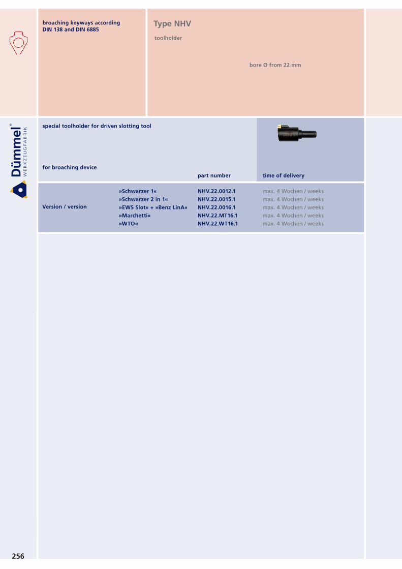
Version / version
»Schwarzer 1«
»Schwarzer 2 in 1«
»EWS Slot« + »Benz LinA«
»Marchetti«
»WTO«
NHV.22.0012.1
NHV.22.0015.1
NHV.22.0016.1
NHV.22.MT16.1
NHV.22.WT16.1
256
Type NHV
toolholder
bore Ø from 22 mm
time of delivery
max. 4 Wochen / weeksmax. 4 Wochen / weeksmax. 4 Wochen / weeksmax. 4 Wochen / weeksmax. 4 Wochen / weeks
part number
for broaching device
special toolholder for driven slotting tool
broaching keyways according
DIN 138 and DIN 6885
pa
rt n
um
be
r
B r f L use
ab
le f
rom
Ø
too
lho
lde
r ty
pe
t m
ax
.
5°
L
5.3
B
r
r
f
t max.
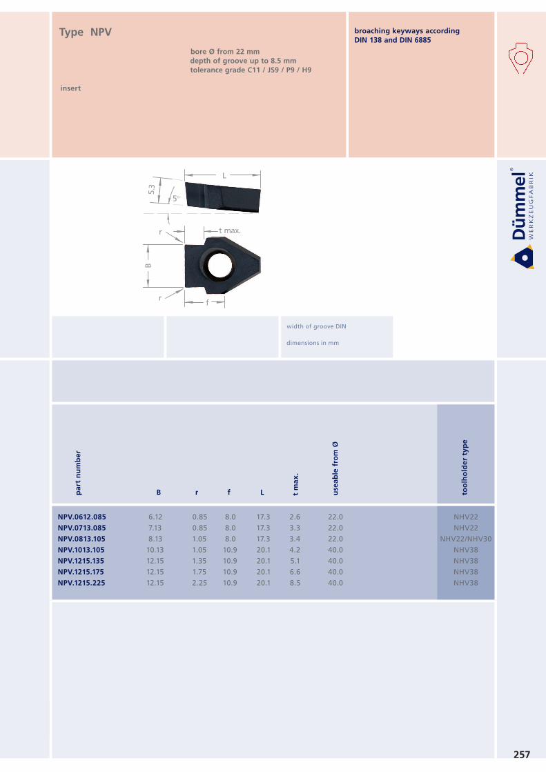
257
NPV.0612.085
NPV.0713.085
NPV.0813.105
NPV.1013.105
NPV.1215.135
NPV.1215.175
NPV.1215.225
6.12
7.13
8.13
10.13
12.15
12.15
12.15
NHV22
NHV22
NHV22/NHV30
NHV38
NHV38
NHV38
NHV38
0.85
0.85
1.05
1.05
1.35
1.75
2.25
8.0
8.0
8.0
10.9
10.9
10.9
10.9
17.3
17.3
17.3
20.1
20.1
20.1
20.1
2.6
3.3
3.4
4.2
5.1
6.6
8.5
22.0
22.0
22.0
40.0
40.0
40.0
40.0
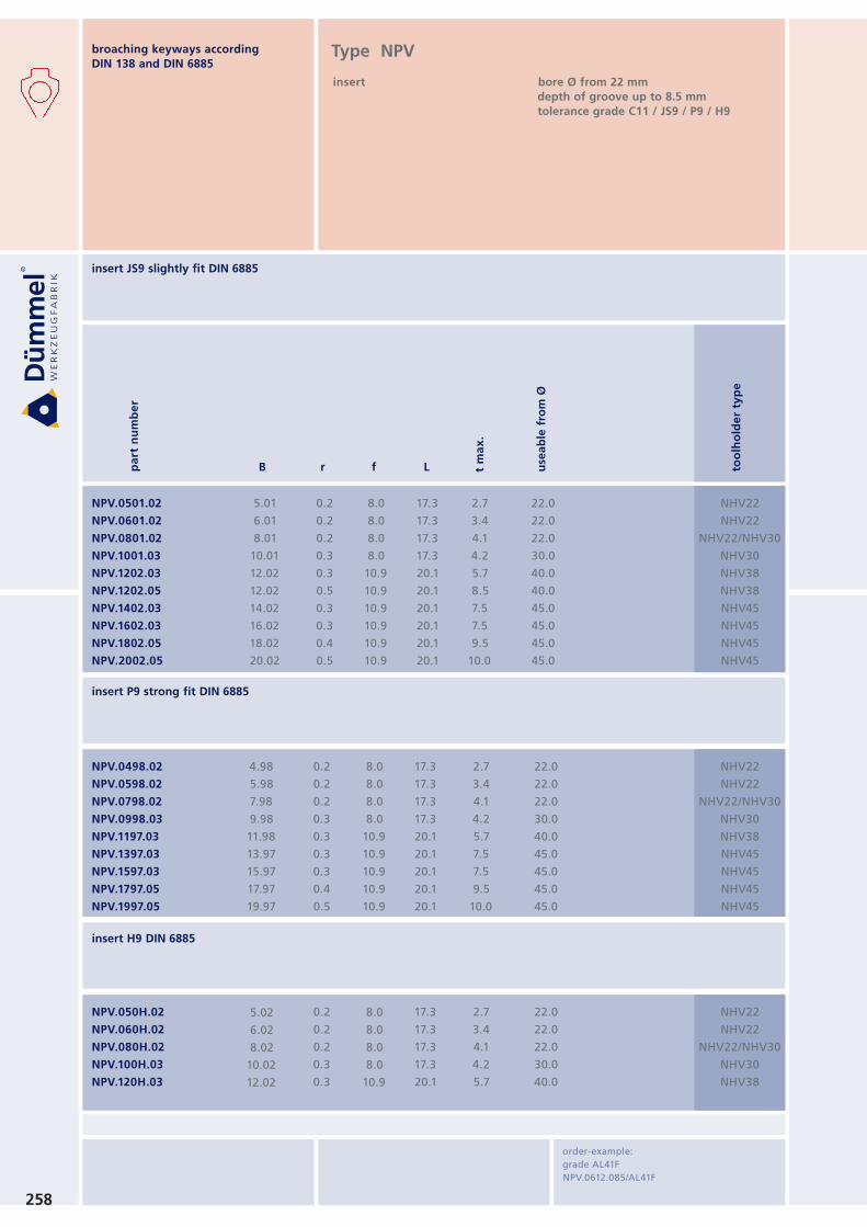
Type NPV
insert
bore Ø from 22 mm
depth of groove up to 8.5 mm tolerance grade C11 / JS9 / P9 / H9
width of groove DIN
dimensions in mm
broaching keyways according
DIN 138 and DIN 6885
258
NPV.0498.02
NPV.0598.02
NPV.0798.02
NPV.0998.03
NPV.1197.03
NPV.1397.03
NPV.1597.03
NPV.1797.05
NPV.1997.05
4.98
5.98
7.98
9.98
11.98
13.97
15.97
17.97
19.97
NHV22
NHV22
NHV22/NHV30
NHV30
NHV38
NHV45
NHV45
NHV45
NHV45
0.2
0.2
0.2
0.3
0.3
0.3
0.3
0.4
0.5
8.0
8.0
8.0
8.0
10.9
10.9
10.9
10.9
10.9
17.3
17.3
17.3
17.3
20.1
20.1
20.1
20.1
20.1
2.7
3.4
4.1
4.2
5.7
7.5
7.5
9.5
10.0
22.0
22.0
22.0
30.0
40.0
45.0
45.0
45.0
45.0
5.02
6.02
8.02
10.02
12.02
0.2
0.2
0.2
0.3
0.3
8.0
8.0
8.0
8.0
10.9
17.3
17.3
17.3
17.3
20.1
2.7
3.4
4.1
4.2
5.7
22.0
22.0
22.0
30.0
40.0
NPV.050H.02
NPV.060H.02
NPV.080H.02
NPV.100H.03
NPV.120H.03
NHV22
NHV22
NHV22/NHV30
NHV30
NHV38
NPV.0501.02
NPV.0601.02
NPV.0801.02
NPV.1001.03
NPV.1202.03
NPV.1202.05
NPV.1402.03
NPV.1602.03
NPV.1802.05
NPV.2002.05
5.01
6.01
8.01
10.01
12.02
12.02
14.02
16.02
18.02
20.02
NHV22
NHV22
NHV22/NHV30
NHV30
NHV38
NHV38
NHV45
NHV45
NHV45
NHV45
0.2
0.2
0.2
0.3
0.3
0.5
0.3
0.3
0.4
0.5
8.0
8.0
8.0
8.0
10.9
10.9
10.9
10.9
10.9
10.9
17.3
17.3
17.3
17.3
20.1
20.1
20.1
20.1
20.1
20.1
2.7
3.4
4.1
4.2
5.7
8.5
7.5
7.5
9.5
10.0
22.0
22.0
22.0
30.0
40.0
40.0
45.0
45.0
45.0
45.0
insert JS9 slightly fit DIN 6885
insert P9 strong fit DIN 6885
insert H9 DIN 6885
order-example:
grade AL41F
NPV.0612.085/AL41F
broaching keyways according
DIN 138 and DIN 6885Type NPV
insert bore Ø from 22 mm
depth of groove up to 8.5 mm tolerance grade C11 / JS9 / P9 / H9
pa
rt n
um
be
r
B r f L use
ab
le f
rom
Ø
too
lho
lde
r ty
pe
t m
ax
.
t2
45° width
45°
45°
L
f
B1
259
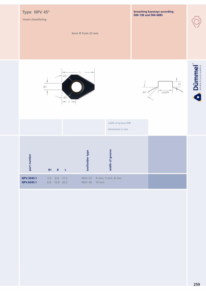
NPV.3045.1
NPV.6045.1
3.5
6.0
8.0
10.9
17.3
20.2
NHV 22
NHV 38
6 mm, 7 mm, 8 mm
10 mm
Type NPV 45°
insert chamfering
bore Ø from 22 mm
width of groove DIN
dimensions in mm
pa
rt n
um
be
r
B1 B L too
lho
lde
r ty
pe
wid
th o
f g
roo
ve
broaching keyways according
DIN 138 and DIN 6885
r rL
L1
BH
+0
.05
Ø 7
.0 h
66
.30
+0
.05f
260
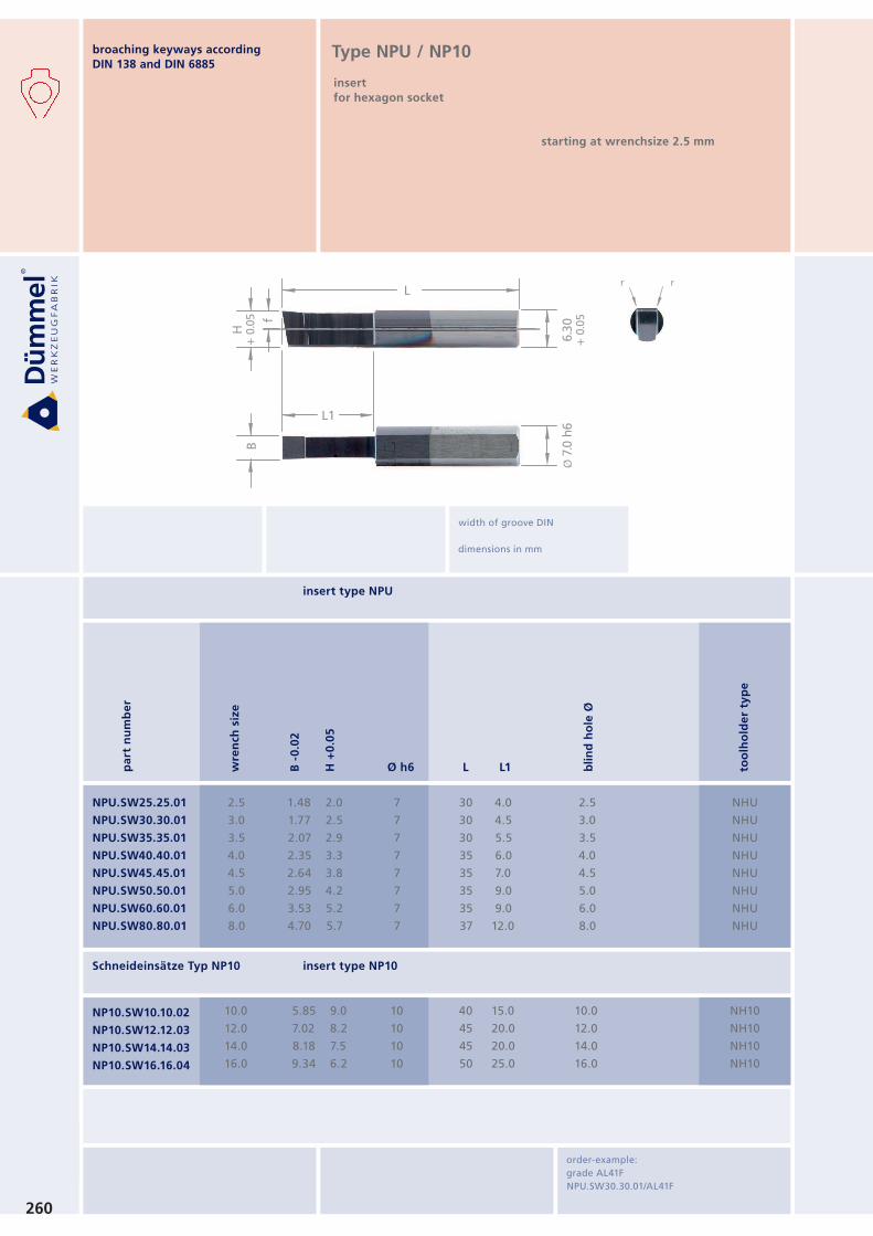
NPU.SW25.25.01
NPU.SW30.30.01
NPU.SW35.35.01
NPU.SW40.40.01
NPU.SW45.45.01
NPU.SW50.50.01
NPU.SW60.60.01
NPU.SW80.80.01
2.5
3.0
3.5
4.0
4.5
5.0
6.0
8.0
1.48
1.77
2.07
2.35
2.64
2.95
3.53
4.70
2.0
2.5
2.9
3.3
3.8
4.2
5.2
5.7
7
7
7
7
7
7
7
7
30
30
30
35
35
35
35
37
NHU
NHU
NHU
NHU
NHU
NHU
NHU
NHU
4.0
4.5
5.5
6.0
7.0
9.0
9.0
12.0
2.5
3.0
3.5
4.0
4.5
5.0
6.0
8.0
NH10
NH10
NH10
NH10
10.0
12.0
14.0
16.0
5.85
7.02
8.18
9.34
9.0
8.2
7.5
6.2
10
10
10
10
40
45
45
50
15.0
20.0
20.0
25.0
10.0
12.0
14.0
16.0
NP10.SW10.10.02
NP10.SW12.12.03
NP10.SW14.14.03
NP10.SW16.16.04
pa
rt n
um
be
r
L L1Ø h6 bli
nd
ho
le Ø
too
lho
lde
r ty
pe
wre
nch
siz
e
B -
0.0
2
H +
0.0
5
Type NPU / NP10
insert
for hexagon socket
starting at wrenchsize 2.5 mm
width of groove DIN
dimensions in mm
insert type NPU
Schneideinsätze Typ NP10 insert type NP10
order-example:
grade AL41F
NPU.SW30.30.01/AL41F
broaching keyways according
DIN 138 and DIN 6885
261
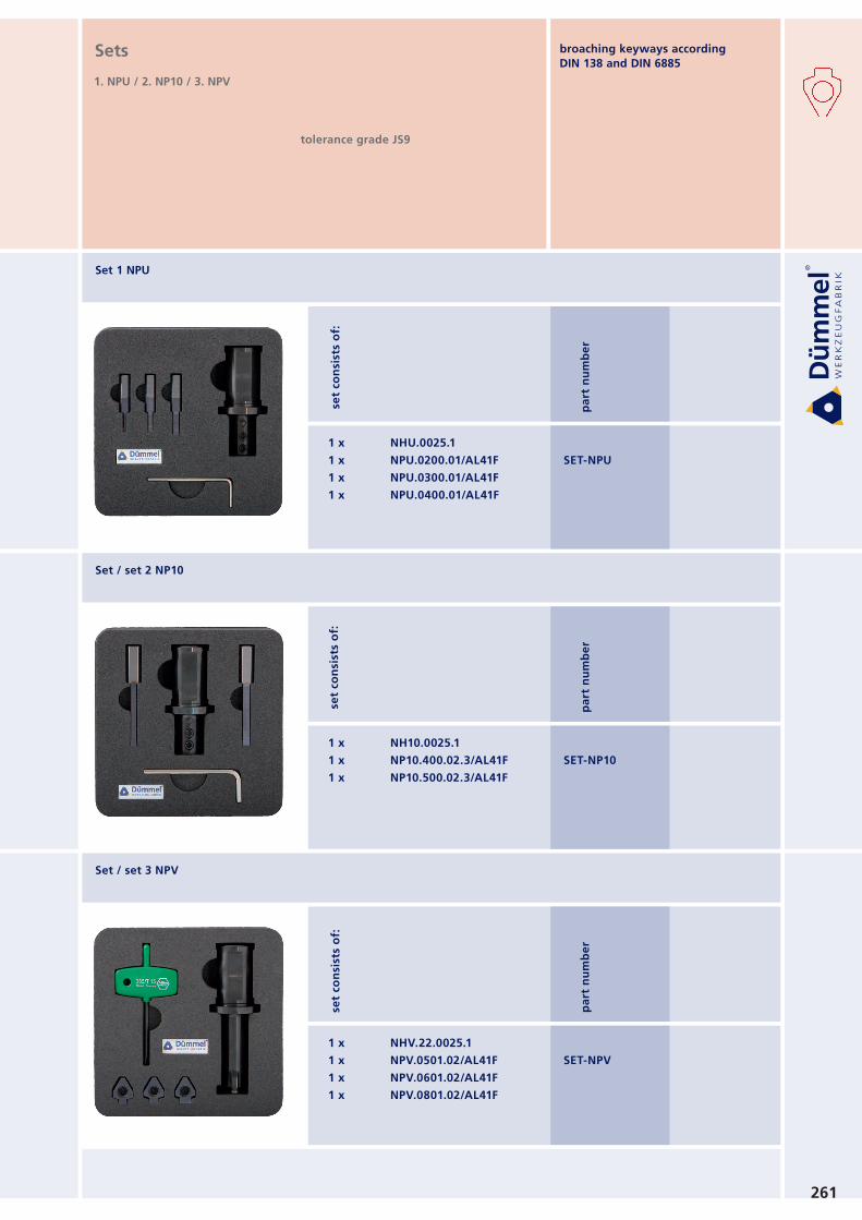
Set 1 NPU
Set / set 2 NP10
Set / set 3 NPV
1 x NHU.0025.1
1 x NPU.0200.01/AL41F
1 x NPU.0300.01/AL41F
1 x NPU.0400.01/AL41F
1 x NH10.0025.1
1 x NP10.400.02.3/AL41F
1 x NP10.500.02.3/AL41F
1 x NHV.22.0025.1
1 x NPV.0501.02/AL41F
1 x NPV.0601.02/AL41F
1 x NPV.0801.02/AL41F
SET-NPU
SET-NP10
SET-NPV
set
con
sist
s o
f: s
et
con
sist
s o
f: s
et
con
sist
s o
f:
Sets
1. NPU / 2. NP10 / 3. NPV
tolerance grade JS9
pa
rt n
um
be
rp
art
nu
mb
er
pa
rt n
um
be
r
broaching keyways according
DIN 138 and DIN 6885
262
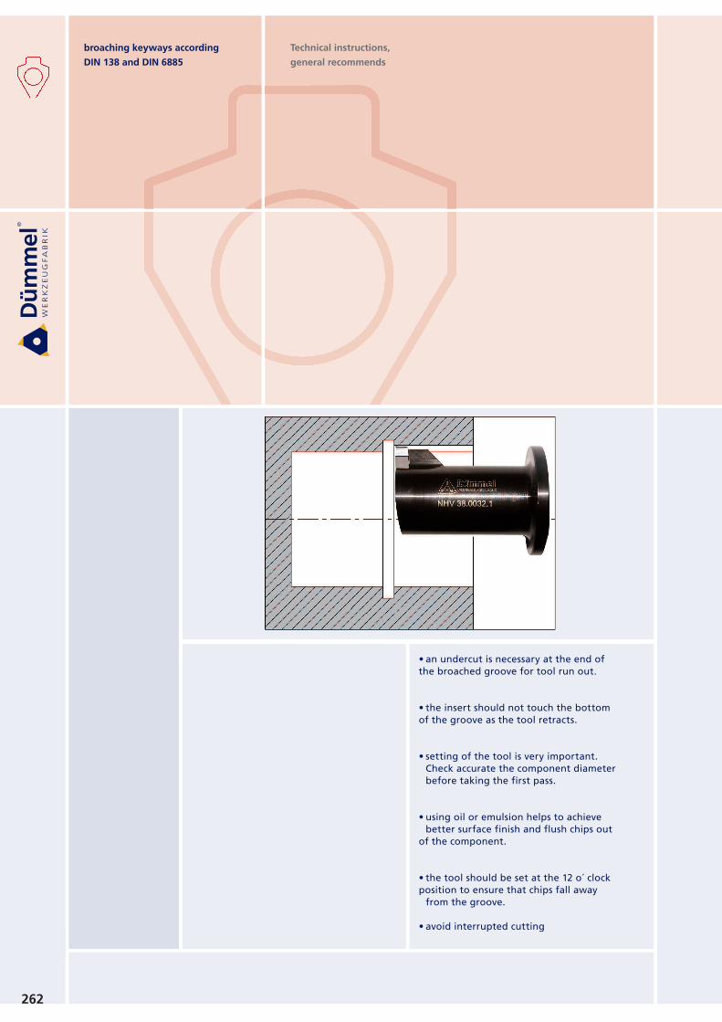
Technical instructions,
general recommends
•anundercutisnecessaryattheendofthe broached groove for tool run out.
•theinsertshouldnottouchthebottomof the groove as the tool retracts.
•settingofthetoolisveryimportant.Check accurate the component diameter
before taking the first pass.
•usingoiloremulsionhelpstoachievebetter surface finish and flush chips out
of the component.
•thetoolshouldbesetatthe12o´clockposition to ensure that chips fall away
from the groove.
•avoidinterruptedcutting
broaching keyways according
DIN 138 and DIN 6885
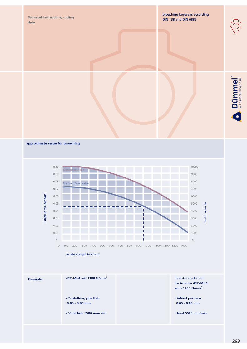
0,10
0,09
0,08
0,07
0,06
0,05
0,04
0,03
0,02
0,01
0
0 100 200 300 400 500 600 700 800 900 1000 1100 1200 1300 1400
10000
9000
8000
7000
6000
5000
4000
3000
2000
1000
0
Obergrenze/limit
Startwert/start value
263
Technical instructions, cutting
data
tensile strength in N/mm2
fee
d i
n m
m/m
in
infe
ed
in
mm
pe
r p
ass
heat-treated steel
for intance 42CrMo4
with 1200 N/mm2
• infeed per pass0.05 - 0.06 mm
• feed 5500 mm/min
42CrMo4 mit 1200 N/mm2
• Zustellung pro Hub0.05 - 0.06 mm
• Vorschub 5500 mm/min
Example:
approximate value for broaching
broaching keyways according
DIN 138 and DIN 6885