stem catalog rev broaching tool usa for …revtoolusa.com/images/revtoolcatalog.pdf · stem....
TRANSCRIPT
THE REVOLUTIONARY TOOLING SYSTEM

2
COMPANY PROFILE
Our Company, F.P. Officina Meccanica (now REV s.r.l.) , was founded in 1998 based on Mr. Paolo Franchini’s 18 years of experience in the mechanics industry. For many years, the Company carried out slotting and broaching activities for third-parties, working in the hydraulic, automotive, biomedical, speed reducers, gear construction and earth moving machinery industries, etc., …Over time, in addition to slotting and broaching, the Company began CNC lathing and milling mechanical parts, which also often involved producing internal keyways, and six-spline PTOs. Not only did it require a large amount of time to set up the various tools, it was also very complicated to perform these processes on traditional broaching and slotting machines due to frequent problems in relation to clamping the workpieces and difficulties in obtaining the required level of precision. The idea of producing, in-house, a tool to perform broaching directly on CNC lathes or machining centres developed from the need to solve these issues and difficulties, and was made possible by extensive experience with CAD CAM design.This is how the “REV Broaching Tool” system for CNC machines was developed, which, after years of designing and a long period of in-house testing, was placed on the market for Companies in need of resolving the same issues that we had in relation to broaching and slotting. The REV Broaching Tool undoubtedly represents an effective solution to these issues, as it allows broaching and slotting to be carried out directly on CNC machine tools (lathes, machining centres, milling machines,
etc.), without having to set up other machines and without having to seek the assistance of subcontractors, plus, it guarantees an excellent finish and is always perfectly within tolerance. Subsequently we enhanced our internal production with several additional lines to enable our product to achieve the largest number of possible applications (tools and inserts for squares, tools and inserts for hexagons, tools for motorised slotters, tools for splined profiles, etc, ...).All the customers that have used the REV Broaching Tool system thus far have expressed great satisfaction with the machining quality and the considerable savings in time and money. Customer satisfaction is our greatest achievement and the best motivation tokeep improving.

3
INTRODUCTION INDEX
The REV Broaching Tool can be used for
processes requiring straight cuts, such as
broaching tab or key housings, PTOs and
internal gears, directly on CNC lathes,
machining centres or milling machines,
considerably faster and with remarkable
precision. In addition to offering the
significant advantage of not having to
pick up the workpiece for broaching or
slotting and set it up on another dedicated
machine, the tool also makes sure the
broaching process is carried out correctly,
at the same time as the other processes.
Used on slotting or shaping machines,
the REV tool represents an excellent
substitute for traditional tools, as it offers
greater versatility thanks to the re-usable
tool body and the replaceable insert.
The high rigidity of the REV Broaching Tool
ensures that the sharp edge of the insert has
an exceptionally long service life and that
broaching or slotting is carried out perfectly
in line with the axis of the workpiece. The
surface finish standard achieved through
processing with this tool is very high. All
of these characteristics together make the
REV system among the most efficient and
convenient mechanical precision processing
systems currently available on the market.
The REV Broaching Tool is available in various
sizes, covering the entire range of the most
common processing sizes, and each insert size
can have various tolerance classes. Special
insert measurements or tool shapes can be
produced very rapidly, on customer demand.
THE REV SYSTEM The REV system for CNC lathes The REV system for CNC milling machines The CNC programmings The REV system for slotters Processings Special tools and inserts Working parameters and performances
TOOLS AND INSERTS Tools for internal Inserts (mm) Inserts (inches) Tools for external Minitool Tools and inserts for square Tools and inserts for hexagon Tools for splined profiles Tools for motorised slotters ACCESSORIES Bushings for lathes Aligners for milling machines Adapters for slotters Resharpeners Screws with spherical ends Screws for fixing inserts Screwdrivers Tool carrier bases
4
4
5
5
6
7
7
7
8
8-9
10-11
12-13
14
15
16-17
18-19
20
21
22
22
23
24
25
26
26
27
28

4
THE REV SYSTEM
The main feature of the REV system for CNC lathes is the eccentric bushing patented by REV S.R.L. (Patent no. 1.394.481) allowing any lathe without a Y-axis to perform broaching or slotting in perfect alignment with the workpiece. It is made with tool steel which is then hardened and ground. Broaching is a process that is almost always perfectly centred on the workpiece, with an error margin of very few hundredths of a millimetre, however, symmetry errors often occur in relation to mechanical coupling between the mounted tool and the centre of the workpiece.The REV eccentric bushing makes it possible to perform a centesimal tool shift by rotating it by a max of 0.5 in Y+ and 0.5 in Y-. This range of adjustment is extensive enough to eliminate any alignment error. A graduated scale is engraved on the front of the bushing, where each notch marks a shift of 0.03 mm. When the first workpiece has been broached, and an error is detected,
the bushing will be adjusted in one direction or the other, to eliminate it. The eccentric bushing is only required if the CNC lathe does not have a Y axis. If, on the other hand, the lathe is equipped with said axis, the eccentric bushing must not be installed and the CNC functions are used to set up the exact position.
ASSEMBLY ON CNC LATHES
CHECKS AND ADJUSTMENTS
FIG.1 FIG.2
In the example provided in Fig. 1 the measured value 8.50 mm is correct, while in Fig.2 the measured value is 8.35 mm on one side and 8.65 on the other, resulting in an alignment error of 0.15 mm that needs to be corrected.
Place the insert in the tool housing and clamp in on by tightening the Torx screw with the screwdriver;Place the tool inside the eccentric bushing and align the white notch engraved on the tool collar with 0 on the front of the bushing; then, tighten the clamping screw positioned radially on the bushing collar, to lock the tool to the bushing;Insert the unit composed of bushing and tool inside the lathe’s boring bar hatch, tighten the screw with the spherical end inside the centering groove on the tool’s socket rod, being careful not to completely block the tool, and finally tighten the two flat point grub screws.
CORRECTING ALIGNMENT ERRORS WITH THE REV BUSHING
When the first key has been processed, one of the ways to check the alignment is to fit a Johansson block, without any room for movement, in the processed housing and, use a gauge to take the measurement between the end of the diameter and the wall of the Johansson block.
If there is an alignment error that needs to be corrected, perform the following operations:
Start by loosening the flat point grub screws that hold the tool in the boring bar hatch and the grub screw positioned radially in the collar of the eccentric bushing, turn the eccentric bushing in the opposite direction of the error; it basically acts as a y axis, moving the tool in Y+ and Y-. Each notch engraved on the bushing is equal to 0.03 mm;
Tighten the clamping grub screw positioned radially on the bushing collar back up, followed by all of the other screws on the boring bar hatch. We advise you to always observe the recommended parameters and suggestions. In the example provided above it would have been necessary to rotate the eccentric bushing by five notches to correct the alignment.
THE REV SYSTEM FOR CNC LATHES

5
For machines that do not feature a spindle alignment function, REV technicians have developed an alignment plate to achieve correct assembly of the REV Broaching Tool on machining centres and milling machines. It is a calibrated bar that needs to be assembled in place of the insert, with a centesimal dial gauge sliding along it (or millesimal, if greater precision is required). When the tool has been centred in relation to the reference axes of the workpiece, the cutting tool can be re-assembled and processing can begin.
Assemble the tool directly on a Weldon fitting (we recommend one with an internal supply);
Position the selector on MDI and place the machine in spindle configuration (for example Fanuc M19);
Place the aligner plate in the insert housing and, using a gauge or comparator, slide the axis along the flat surface of the plate until you achieve perfect alignment, parallel to the direction of operation;
Tighten the bolts on the Weldon fitting so as to clamp the tool on, then remove the aligner plate and put the insert in place.
ASSEMBLY ON CNC MILLING MACHINES
The REV Broaching Tool technicians have developed CNC programmes for tool operation. These are provided free of charge on customer demand through access to the reserved area of our website. They are developed for the most common types of CNC control currently available on the market.
Using these programmes it is very easy for the operator to process simple key housings and conical internal gears, quickly and efficiently.
THE REV SYSTEM FOR CNC MILLING MACHINES
CNC PROGRAMMINGS

6
ASSEMBLY ON SLOTTERS
Place the insert in the tool housing and clamp in on by tightening the Torx screw with the screwdriver;
Insert the tool inside the square or prismatic adapter and lock it in place using the flat point grub screws;
Attach the square or prismatic adapter to the slotting or shaping machine.
The REV Broaching Tool can be used, in addition to CNC machining centres and lathes, also on traditional machines such as slotting and shaping machines, offering great sturdiness and versatile use, unlike tools commonly used on these machines. To clamp the tool to slotting and shaping machines, the REV system offers an adapter (square or prismatic) that makes it possible to process the hole in four positions at 90° angles to each other. It is made with 39NiCrMO3 which, through tempering, reaches a hardness of 58/60 HRC and is then ground. The toughness and rigidity of this material make it possible to achieve processing with an excellent surface finish. The adapter (square or prismatic) is equipped with two threaded holes where the two M12x8 flat point grub screws are inserted and used to clamp the tool to the inside of the adapter. The timing pin guarantees a perfect position of the tool in relation to the work axis. REV offers the solution of clamping the tool on by a square or prismatic adapter, however, this is only one of the many ways it is possible to set up the REV Broaching Tool on slotting and shaping machines. REV technicians are in fact able to adapt the tool to all slotting and shaping machines on the market by modifying the part designed for clamping to the machine.
THE REV SYSTEM FOR SLOTTERS
7
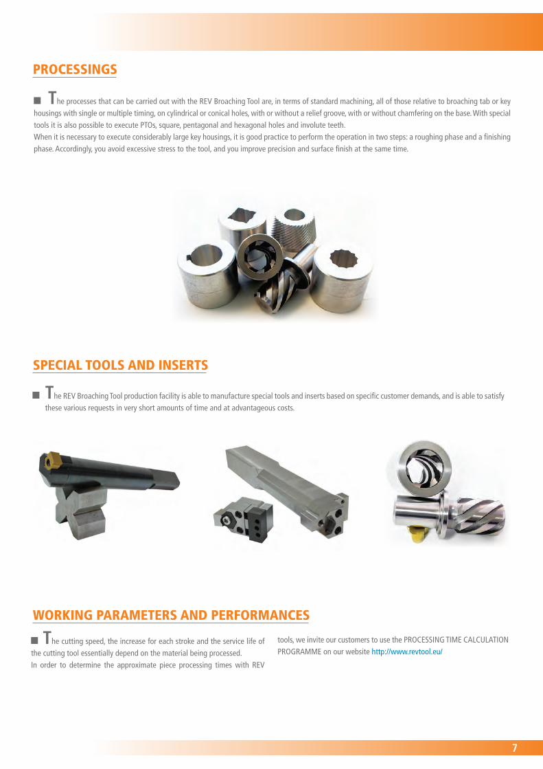
The processes that can be carried out with the REV Broaching Tool are, in terms of standard machining, all of those relative to broaching tab or key housings with single or multiple timing, on cylindrical or conical holes, with or without a relief groove, with or without chamfering on the base. With special tools it is also possible to execute PTOs, square, pentagonal and hexagonal holes and involute teeth.When it is necessary to execute considerably large key housings, it is good practice to perform the operation in two steps: a roughing phase and a finishing phase. Accordingly, you avoid excessive stress to the tool, and you improve precision and surface finish at the same time.
PROCESSINGS
The REV Broaching Tool production facility is able to manufacture special tools and inserts based on specific customer demands, and is able to satisfy these various requests in very short amounts of time and at advantageous costs.
SPECIAL TOOLS AND INSERTS
The cutting speed, the increase for each stroke and the service life of the cutting tool essentially depend on the material being processed.In order to determine the approximate piece processing times with REV
tools, we invite our customers to use the PROCESSING TIME CALCULATION PROGRAMME on our website http://www.revtool.eu/
WORKING PARAMETERS AND PERFORMANCES
8
CODE L1 (mm) L2 (mm) L3 (mm) L4 (mm) D1 (mm) D2 (mm) D3 (mm) Aligner Screwdriver Clamping screw
Minimum hole (mm)
Weight (g)
UT-02-25* 25 124 9 90 25 6 30 PN-0 T08 VN-1 7 382
UT-02-25-L* 34,5 133,5 9 90 25 6 30 PN-0 T08 VN-1 7 354
UT-02-32* 25 134 9 100 32 6 37 PN-0 T08 VN-1 7 600
UT-02-32-L* 34,5 143,5 9 100 32 6 37 PN-0 T08 VN-1 7 654
UT-03-25* 30 129 9 90 25 8 30 PN-1 T08 VN-1 8,7 368
UT-03-25-L* 40 139 9 90 25 8 30 PN-1 T08 VN-1 8,7 362
UT-03-32* 30 139 9 100 32 8 37 PN-1 T08 VN-1 8,7 673
UT-03-32-L* 40 149 9 100 32 8 37 PN-1 T08 VN-1 8,7 678
UT-04-25* 40 139 9 90 25 10 30 PN-1 T08 VN-1 11 368
UT-04-25-L* 56 155 9 90 25 10 30 PN-1 T08 VN-1 11 377
UT-04-32* 40 149 9 100 32 10 37 PN-1 T08 VN-1 11 672
UT-04-32-L* 56 165 9 100 32 10 37 PN-1 T08 VN-1 11 684
UT-05-25* 46 145 9 90 25 12 30 PN-1 T08 VN-1 13 382
UT-05-25-L* 66 165 9 90 25 12 30 PN-1 T08 VN-1 13 408
UT-05-32* 46 155 9 100 32 12 37 PN-1 T08 VN-1 13 698
UT-05-32-L* 66 175 9 100 32 12 37 PN-1 T08 VN-1 13 711
UT-06-25* 56 155 9 90 25 16 30 PN-2 T15 VN-2 17 428
UT-06-25-L* 81 180 9 90 25 16 30 PN-2 T15 VN-2 17 453
UT-06-32* 56 165 9 100 32 16 37 PN-2 T15 VN-2 17 725
UT-06-32-L* 81 190 9 100 32 16 37 PN-2 T15 VN-2 17 765
UT-08-25* 68 167 9 90 25 20 30 PN-2 T15 VN-2 21,5 488
UT-08-25-L* 100 199 9 90 25 20 30 PN-2 T15 VN-2 21,5 574
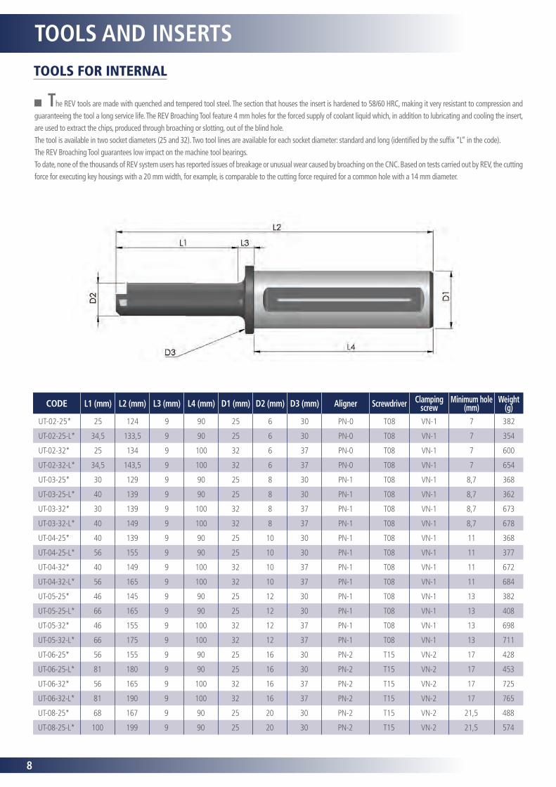
TOOLS AND INSERTSTOOLS FOR INTERNAL
The REV tools are made with quenched and tempered tool steel. The section that houses the insert is hardened to 58/60 HRC, making it very resistant to compression and guaranteeing the tool a long service life. The REV Broaching Tool feature 4 mm holes for the forced supply of coolant liquid which, in addition to lubricating and cooling the insert, are used to extract the chips, produced through broaching or slotting, out of the blind hole.The tool is available in two socket diameters (25 and 32). Two tool lines are available for each socket diameter: standard and long (identified by the suffix “L” in the code). The REV Broaching Tool guarantees low impact on the machine tool bearings. To date, none of the thousands of REV system users has reported issues of breakage or unusual wear caused by broaching on the CNC. Based on tests carried out by REV, the cutting force for executing key housings with a 20 mm width, for example, is comparable to the cutting force required for a common hole with a 14 mm diameter.
9
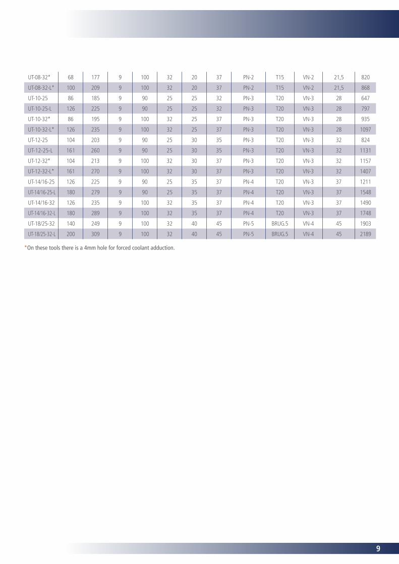
*On these tools there is a 4mm hole for forced coolant adduction.
UT-08-32* 68 177 9 100 32 20 37 PN-2 T15 VN-2 21,5 820
UT-08-32-L* 100 209 9 100 32 20 37 PN-2 T15 VN-2 21,5 868
UT-10-25 86 185 9 90 25 25 32 PN-3 T20 VN-3 28 647
UT-10-25-L 126 225 9 90 25 25 32 PN-3 T20 VN-3 28 797
UT-10-32* 86 195 9 100 32 25 37 PN-3 T20 VN-3 28 935
UT-10-32-L* 126 235 9 100 32 25 37 PN-3 T20 VN-3 28 1097
UT-12-25 104 203 9 90 25 30 35 PN-3 T20 VN-3 32 824
UT-12-25-L 161 260 9 90 25 30 35 PN-3 T20 VN-3 32 1131
UT-12-32* 104 213 9 100 32 30 37 PN-3 T20 VN-3 32 1157
UT-12-32-L* 161 270 9 100 32 30 37 PN-3 T20 VN-3 32 1407
UT-14/16-25 126 225 9 90 25 35 37 PN-4 T20 VN-3 37 1211
UT-14/16-25-L 180 279 9 90 25 35 37 PN-4 T20 VN-3 37 1548
UT-14/16-32 126 235 9 100 32 35 37 PN-4 T20 VN-3 37 1490
UT-14/16-32-L 180 289 9 100 32 35 37 PN-4 T20 VN-3 37 1748
UT-18/25-32 140 249 9 100 32 40 45 PN-5 BRUG.5 VN-4 45 1903
UT-18/25-32-L 200 309 9 100 32 40 45 PN-5 BRUG.5 VN-4 45 2189
10
Chamfer 0,2x45°
L3
L4
L5
L1
L6
L2
Refer to the SM series
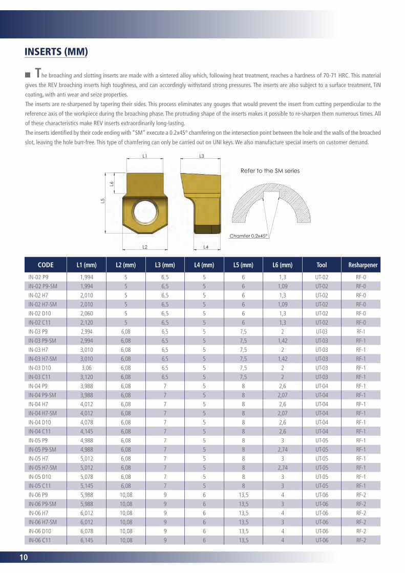
CODE L1 (mm) L2 (mm) L3 (mm) L4 (mm) L5 (mm) L6 (mm) Tool Resharpener
IN-02 P9 1,994 5 6,5 5 6 1,3 UT-02 RF-0
IN-02 P9-SM 1,994 5 6,5 5 6 1,09 UT-02 RF-0
IN-02 H7 2,010 5 6,5 5 6 1,3 UT-02 RF-0
IN-02 H7-SM 2,010 5 6,5 5 6 1,09 UT-02 RF-0
IN-02 D10 2,060 5 6,5 5 6 1,3 UT-02 RF-0
IN-02 C11 2,120 5 6,5 5 6 1,3 UT-02 RF-0
IN-03 P9 2,994 6,08 6,5 5 7,5 2 UT-03 RF-1
IN-03 P9-SM 2,994 6,08 6,5 5 7,5 1,42 UT-03 RF-1
IN-03 H7 3,010 6,08 6,5 5 7,5 2 UT-03 RF-1
IN-03 H7-SM 3,010 6,08 6,5 5 7,5 1,42 UT-03 RF-1
IN-03 D10 3,06 6,08 6,5 5 7,5 2 UT-03 RF-1
IN-03 C11 3,120 6,08 6,5 5 7,5 2 UT-03 RF-1
IN-04 P9 3,988 6,08 7 5 8 2,6 UT-04 RF-1
IN-04 P9-SM 3,988 6,08 7 5 8 2,07 UT-04 RF-1
IN-04 H7 4,012 6,08 7 5 8 2,6 UT-04 RF-1
IN-04 H7-SM 4,012 6,08 7 5 8 2,07 UT-04 RF-1
IN-04 D10 4,078 6,08 7 5 8 2,6 UT-04 RF-1
IN-04 C11 4,145 6,08 7 5 8 2,6 UT-04 RF-1
IN-05 P9 4,988 6,08 7 5 8 3 UT-05 RF-1
IN-05 P9-SM 4,988 6,08 7 5 8 2,74 UT-05 RF-1
IN-05 H7 5,012 6,08 7 5 8 3 UT-05 RF-1
IN-05 H7-SM 5,012 6,08 7 5 8 2,74 UT-05 RF-1
IN-05 D10 5,078 6,08 7 5 8 3 UT-05 RF-1
IN-05 C11 5,145 6,08 7 5 8 3 UT-05 RF-1
IN-06 P9 5,988 10,08 9 6 13,5 4 UT-06 RF-2
IN-06 P9-SM 5,988 10,08 9 6 13,5 3 UT-06 RF-2
IN-06 H7 6,012 10,08 9 6 13,5 4 UT-06 RF-2
IN-06 H7-SM 6,012 10,08 9 6 13,5 3 UT-06 RF-2
IN-06 D10 6,078 10,08 9 6 13,5 4 UT-06 RF-2
IN-06 C11 6,145 10,08 9 6 13,5 4 UT-06 RF-2
INSERTS (MM)
The broaching and slotting inserts are made with a sintered alloy which, following heat treatment, reaches a hardness of 70-71 HRC. This material
gives the REV broaching inserts high toughness, and can accordingly withstand strong pressures. The inserts are also subject to a surface treatment, TiN
coating, with anti wear and seize properties.
The inserts are re-sharpened by tapering their sides. This process eliminates any gouges that would prevent the insert from cutting perpendicular to the
reference axis of the workpiece during the broaching phase. The protruding shape of the inserts makes it possible to re-sharpen them numerous times. All
of these characteristics make REV inserts extraordinarily long-lasting.
The inserts identified by their code ending with “SM” execute a 0.2x45° chamfering on the intersection point between the hole and the walls of the broached
slot, leaving the hole burr-free. This type of chamfering can only be carried out on UNI keys. We also manufacture special inserts on customer demand.

11
IN-08 P9 7,985 10,08 9 6 13,5 4,5 UT-08 RF-2
IN-08 P9-SM 7,985 10,08 9 6 13,5 3,78 UT-08 RF-2
IN-08 H7 8,015 10,08 9 6 13,5 4,5 UT-08 RF-2
IN-08 H7-SM 8,015 10,08 9 6 13,5 3,78 UT-08 RF-2
IN-08 D10 8,098 10,08 9 6 13,5 4,5 UT-08 RF-2
IN-08 C11 8,170 10,08 9 6 13,5 4,5 UT-08 RF-2
IN-10 P9 9,985 13,1 14 10 18,5 6 UT-10 RF-3
IN-10 P9-SM 9,985 13,1 14 10 18,5 3,88 UT-10 RF-3
IN-10 H7 10,015 13,1 14 10 18,5 6 UT-10 RF-3
IN-10 H7-SM 10,015 13,1 14 10 18,5 3,88 UT-10 RF-3
IN-10 D10 10,098 13,1 14 10 18,5 6 UT-10 RF-3
IN-10 C11 10,170 13,1 14 10 18,5 6 UT-10 RF-3
IN-12 P9 11,982 13,1 14 10 18,5 6,5 UT-12 RF-3
IN-12 P9-SM 11,982 13,1 14 10 18,5 3,89 UT-12 RF-3
IN-12 H7 12,018 13,1 14 10 18,5 6,5 UT-12 RF-3
IN-12 H7-SM 12,018 13,1 14 10 18,5 3,89 UT-12 RF-3
IN-12 D10 12,12 13,1 14 10 18,5 6,5 UT-12 RF-3
IN-12 C11 12,205 13,1 14 10 18,5 6,5 UT-12 RF-3
IN-14 P9 13,982 18 14 10 22 7 UT-14/16 RF-4
IN-14 P9-SM 13,982 18 14 10 22 4,71 UT-14/16 RF-4
IN-14 H7 14,018 18 14 10 22 7 UT-14/16 RF-4
IN-14 H7-SM 14,018 18 14 10 22 4,71 UT-14/16 RF-4
IN-14 D10 14,120 18 14 10 22 7 UT-14/16 RF-4
IN-14 C11 14,205 18 14 10 22 7 UT-14/16 RF-4
IN-16 P9 15,982 18 14 10 22 8 UT-14/16 RF-4
IN-16 P9-SM 15,982 18 14 10 22 5,53 UT-14/16 RF-4
IN-16 H7 16,018 18 14 10 22 8 UT-14/16 RF-4
IN-16 H7-SM 16,018 18 14 10 22 5,53 UT-14/16 RF-4
IN-16 D10 16,120 18 14 10 22 8 UT-14/16 RF-4
IN-16 C11 16,205 18 14 10 22 8 UT-14/16 RF-4
IN-18 P9** 17,982 26 18 10 30 9 UT-18/25 RF-5
IN-18 P9-SM** 17,982 26 18 10 30 5,67 UT-18/25 RF-5
IN-18 H7** 18,018 26 18 10 30 9 UT-18/25 RF-5
IN-18 H7-SM** 18,018 26 18 10 30 5,67 UT-18/25 RF-5
IN-18 D10** 18,120 26 18 10 30 9 UT-18/25 RF-5
IN-18 C11** 18,205 26 18 10 30 9 UT-18/25 RF-5
IN-20 P9** 19,978 26 18 10 30 10 UT-18/25 RF-5
IN-20 P9-SM** 19,978 26 18 10 30 6,29 UT-18/25 RF-5
IN-20 H7** 20,021 26 18 10 30 10 UT-18/25 RF-5
IN-20 H7-SM** 20,021 26 18 10 30 6,29 UT-18/25 RF-5
IN-20 D10** 20,149 26 18 10 30 10 UT-18/25 RF-5
IN-20 C11** 20,240 26 18 10 30 10 UT-18/25 RF-5
IN-22 P9** 21,978 26 18 10 30 11 UT-18/25 RF-5
IN-22 P9-SM** 21,978 26 18 10 30 6,79 UT-18/25 RF-5
IN-22 H7** 22,021 26 18 10 30 11 UT-18/25 RF-5
IN-22 H7-SM** 22,021 26 18 10 30 6,79 UT-18/25 RF-5
IN-22 D10** 22,149 26 18 10 30 11 UT-18/25 RF-5
IN-22 C11** 22,240 26 18 10 30 11 UT-18/25 RF-5
IN-25 P9** 24,978 26 18 10 30 12 UT-18/25 RF-5
IN-25 P9-SM** 24,978 26 18 10 30 7,02 UT-18/25 RF-5
IN-25 H7** 25,021 26 18 10 30 12 UT-18/25 RF-5
IN-25 H7-SM** 25,021 26 18 10 30 7,02 UT-18/25 RF-5
IN-25 D10** 25,149 26 18 10 30 12 UT-18/25 RF-5
IN-25 C11** 25,240 26 18 10 30 12 UT-18/25 RF-5
**For these insert sizes we recommend machining in two steps: roughing and finishing.
12
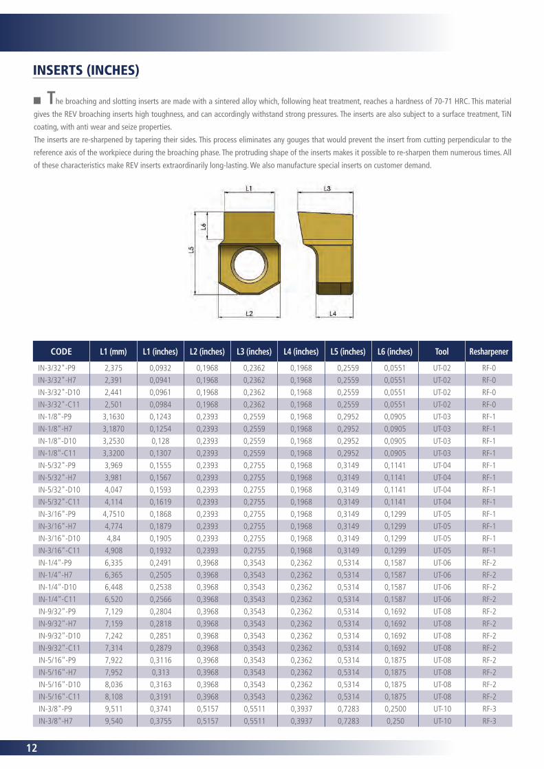
The broaching and slotting inserts are made with a sintered alloy which, following heat treatment, reaches a hardness of 70-71 HRC. This material
gives the REV broaching inserts high toughness, and can accordingly withstand strong pressures. The inserts are also subject to a surface treatment, TiN
coating, with anti wear and seize properties.
The inserts are re-sharpened by tapering their sides. This process eliminates any gouges that would prevent the insert from cutting perpendicular to the
reference axis of the workpiece during the broaching phase. The protruding shape of the inserts makes it possible to re-sharpen them numerous times. All
of these characteristics make REV inserts extraordinarily long-lasting. We also manufacture special inserts on customer demand.
INSERTS (INCHES)
CODE L1 (mm) L1 (inches) L2 (inches) L3 (inches) L4 (inches) L5 (inches) L6 (inches) Tool Resharpener
IN-3/32"-P9 2,375 0,0932 0,1968 0,2362 0,1968 0,2559 0,0551 UT-02 RF-0
IN-3/32"-H7 2,391 0,0941 0,1968 0,2362 0,1968 0,2559 0,0551 UT-02 RF-0
IN-3/32"-D10 2,441 0,0961 0,1968 0,2362 0,1968 0,2559 0,0551 UT-02 RF-0
IN-3/32"-C11 2,501 0,0984 0,1968 0,2362 0,1968 0,2559 0,0551 UT-02 RF-0
IN-1/8"-P9 3,1630 0,1243 0,2393 0,2559 0,1968 0,2952 0,0905 UT-03 RF-1
IN-1/8"-H7 3,1870 0,1254 0,2393 0,2559 0,1968 0,2952 0,0905 UT-03 RF-1
IN-1/8"-D10 3,2530 0,128 0,2393 0,2559 0,1968 0,2952 0,0905 UT-03 RF-1
IN-1/8"-C11 3,3200 0,1307 0,2393 0,2559 0,1968 0,2952 0,0905 UT-03 RF-1
IN-5/32"-P9 3,969 0,1555 0,2393 0,2755 0,1968 0,3149 0,1141 UT-04 RF-1
IN-5/32"-H7 3,981 0,1567 0,2393 0,2755 0,1968 0,3149 0,1141 UT-04 RF-1
IN-5/32"-D10 4,047 0,1593 0,2393 0,2755 0,1968 0,3149 0,1141 UT-04 RF-1
IN-5/32"-C11 4,114 0,1619 0,2393 0,2755 0,1968 0,3149 0,1141 UT-04 RF-1
IN-3/16"-P9 4,7510 0,1868 0,2393 0,2755 0,1968 0,3149 0,1299 UT-05 RF-1
IN-3/16"-H7 4,774 0,1879 0,2393 0,2755 0,1968 0,3149 0,1299 UT-05 RF-1
IN-3/16"-D10 4,84 0,1905 0,2393 0,2755 0,1968 0,3149 0,1299 UT-05 RF-1
IN-3/16"-C11 4,908 0,1932 0,2393 0,2755 0,1968 0,3149 0,1299 UT-05 RF-1
IN-1/4"-P9 6,335 0,2491 0,3968 0,3543 0,2362 0,5314 0,1587 UT-06 RF-2
IN-1/4"-H7 6,365 0,2505 0,3968 0,3543 0,2362 0,5314 0,1587 UT-06 RF-2
IN-1/4"-D10 6,448 0,2538 0,3968 0,3543 0,2362 0,5314 0,1587 UT-06 RF-2
IN-1/4"-C11 6,520 0,2566 0,3968 0,3543 0,2362 0,5314 0,1587 UT-06 RF-2
IN-9/32"-P9 7,129 0,2804 0,3968 0,3543 0,2362 0,5314 0,1692 UT-08 RF-2
IN-9/32"-H7 7,159 0,2818 0,3968 0,3543 0,2362 0,5314 0,1692 UT-08 RF-2
IN-9/32"-D10 7,242 0,2851 0,3968 0,3543 0,2362 0,5314 0,1692 UT-08 RF-2
IN-9/32"-C11 7,314 0,2879 0,3968 0,3543 0,2362 0,5314 0,1692 UT-08 RF-2
IN-5/16"-P9 7,922 0,3116 0,3968 0,3543 0,2362 0,5314 0,1875 UT-08 RF-2
IN-5/16"-H7 7,952 0,313 0,3968 0,3543 0,2362 0,5314 0,1875 UT-08 RF-2
IN-5/16"-D10 8,036 0,3163 0,3968 0,3543 0,2362 0,5314 0,1875 UT-08 RF-2
IN-5/16"-C11 8,108 0,3191 0,3968 0,3543 0,2362 0,5314 0,1875 UT-08 RF-2
IN-3/8"-P9 9,511 0,3741 0,5157 0,5511 0,3937 0,7283 0,2500 UT-10 RF-3
IN-3/8"-H7 9,540 0,3755 0,5157 0,5511 0,3937 0,7283 0,250 UT-10 RF-3
13
IN-3/8"-D10 9,623 0,3788 0,5157 0,5511 0,3937 0,7283 0,250 UT-10 RF-3
IN-3/8"-C11 9,695 0,3816 0,5157 0,5511 0,3937 0,7283 0,250 UT-10 RF-3
IN-7/16"-P9 11,094 0,4364 0,5157 0,5511 0,3937 0,7283 0,250 UT-12 RF-3
IN-7/16"-H7 11,13 0,4382 0,5157 0,5511 0,3937 0,7283 0,250 UT-12 RF-3
IN-7/16"-D10 11,232 0,4422 0,5157 0,5511 0,3937 0,7283 0,250 UT-12 RF-3
IN-7/16"-C11 11,318 0,4455 0,5157 0,5511 0,3937 0,7283 0,250 UT-12 RF-3
IN-1/2"-P9 12,682 0,4989 0,5157 0,5511 0,3937 0,7283 0,300 UT-12 RF-3
IN-1/2"-H7 12,718 0,5007 0,5157 0,5511 0,3937 0,7283 0,300 UT-12 RF-3
IN-1/2"-D10 12,8200 0,5047 0,5157 0,5511 0,3937 0,7283 0,300 UT-12 RF-3
IN-1/2"-C11 12,9050 0,508 0,5157 0,5511 0,3937 0,7283 0,300 UT-12 RF-3
IN-9/16"-P9 14,27 0,5614 0,7086 0,5511 0,3937 0,8661 0,275 UT-14/16 RF-4
IN-9/16"-H7 14,306 0,5632 0,7086 0,5511 0,3937 0,8661 0,275 UT-14/16 RF-4
IN-9/16"-D10 14,408 0,5672 0,7086 0,5511 0,3937 0,8661 0,275 UT-14/16 RF-4
IN-9/16"-C11 14,492 0,5705 0,7086 0,5511 0,3937 0,8661 0,275 UT-14/16 RF-4
IN-5/8"-P9 15,8570 0,6239 0,7086 0,5511 0,3937 0,8661 0,312 UT-14/16 RF-4
IN-5/8"-H7 15,8930 0,6257 0,7086 0,5511 0,3937 0,8661 0,312 UT-14/16 RF-4
IN-5/8"-D10 15,9950 0,6297 0,7086 0,5511 0,3937 0,8661 0,312 UT-14/16 RF-4
IN-5/8"-C11 16,080 0,633 0,7086 0,5511 0,3937 0,8661 0,312 UT-14/16 RF-4
IN-3/4"-P9** 19,028 0,7487 1,024 0,7086 0,3937 1,181 0,393 UT-18/25 RF-5
IN-3/4"-H7** 19,071 0,7508 1,024 0,7086 0,3937 1,181 0,393 UT-18/25 RF-5
IN-3/4"-D10** 19,199 0,7558 1,024 0,7086 0.3937 1,181 0,393 UT-18/25 RF-5
IN-3/4"-C11** 19,290 0,7594 1,024 0,7086 0,3937 1,181 0,393 UT-18/25 RF-5
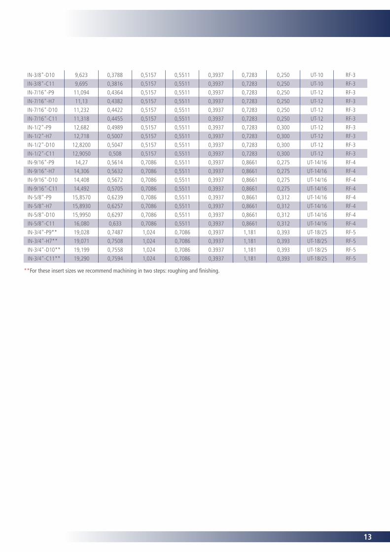
**For these insert sizes we recommend machining in two steps: roughing and finishing.
14
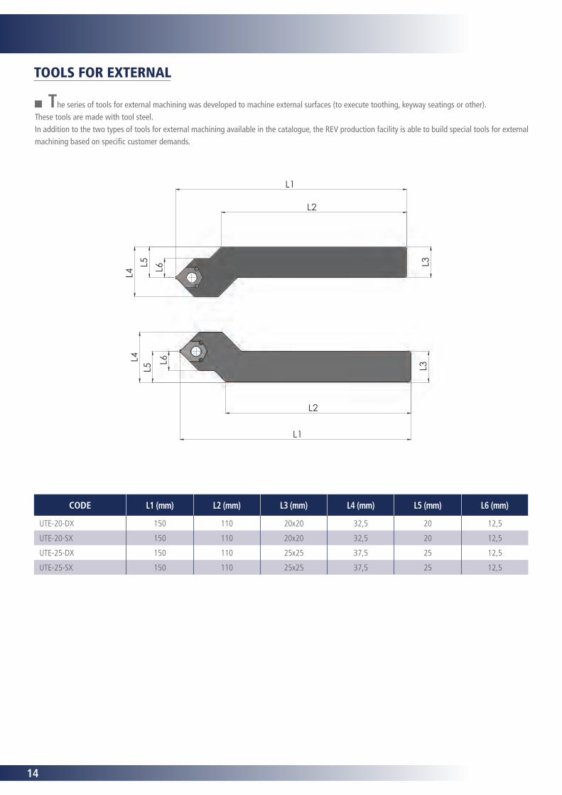
The series of tools for external machining was developed to machine external surfaces (to execute toothing, keyway seatings or other).These tools are made with tool steel.In addition to the two types of tools for external machining available in the catalogue, the REV production facility is able to build special tools for external machining based on specific customer demands.
TOOLS FOR EXTERNAL
L6
L5 L3L2
L1
L4L5 L6 L3
L1
L2
L4
CODE L1 (mm) L2 (mm) L3 (mm) L4 (mm) L5 (mm) L6 (mm)
UTE-20-DX 150 110 20x20 32,5 20 12,5
UTE-20-SX 150 110 20x20 32,5 20 12,5
UTE-25-DX 150 110 25x25 37,5 25 12,5
UTE-25-SX 150 110 25x25 37,5 25 12,5
15
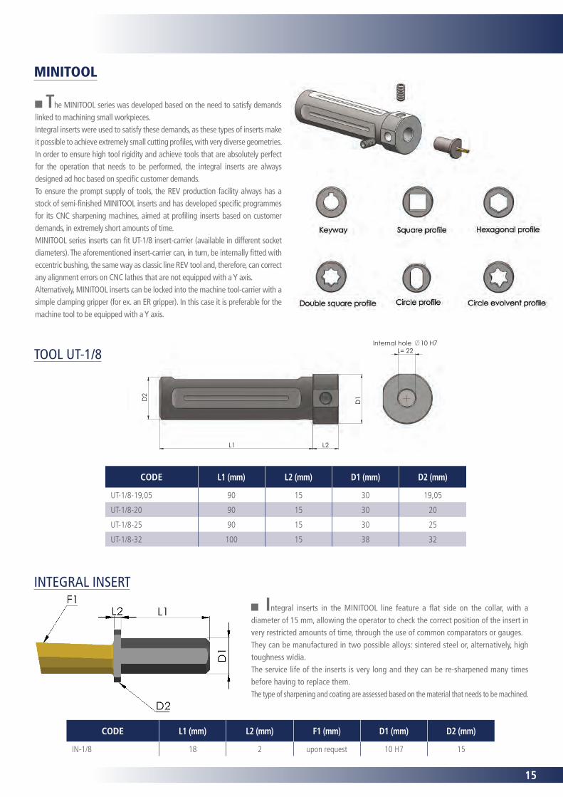
MINITOOL
The MINITOOL series was developed based on the need to satisfy demands linked to machining small workpieces.Integral inserts were used to satisfy these demands, as these types of inserts make it possible to achieve extremely small cutting profiles, with very diverse geometries.In order to ensure high tool rigidity and achieve tools that are absolutely perfect for the operation that needs to be performed, the integral inserts are always designed ad hoc based on specific customer demands.To ensure the prompt supply of tools, the REV production facility always has a stock of semi-finished MINITOOL inserts and has developed specific programmes for its CNC sharpening machines, aimed at profiling inserts based on customer demands, in extremely short amounts of time.MINITOOL series inserts can fit UT-1/8 insert-carrier (available in different socket diameters). The aforementioned insert-carrier can, in turn, be internally fitted with eccentric bushing, the same way as classic line REV tool and, therefore, can correct any alignment errors on CNC lathes that are not equipped with a Y axis.Alternatively, MINITOOL inserts can be locked into the machine tool-carrier with a simple clamping gripper (for ex. an ER gripper). In this case it is preferable for the machine tool to be equipped with a Y axis.
CODE L1 (mm) L2 (mm) D1 (mm) D2 (mm)
UT-1/8-19,05 90 15 30 19,05
UT-1/8-20 90 15 30 20
UT-1/8-25 90 15 30 25
UT-1/8-32 100 15 38 32
L2
D2
L1
D1
Internal hole 10 H7L= 22TOOL UT-1/8
INTEGRAL INSERT
Integral inserts in the MINITOOL line feature a flat side on the collar, with a diameter of 15 mm, allowing the operator to check the correct position of the insert in very restricted amounts of time, through the use of common comparators or gauges.They can be manufactured in two possible alloys: sintered steel or, alternatively, high toughness widia.The service life of the inserts is very long and they can be re-sharpened many times before having to replace them.The type of sharpening and coating are assessed based on the material that needs to be machined.
CODE L1 (mm) L2 (mm) F1 (mm) D1 (mm) D2 (mm)
IN-1/8 18 2 upon request 10 H7 15
16
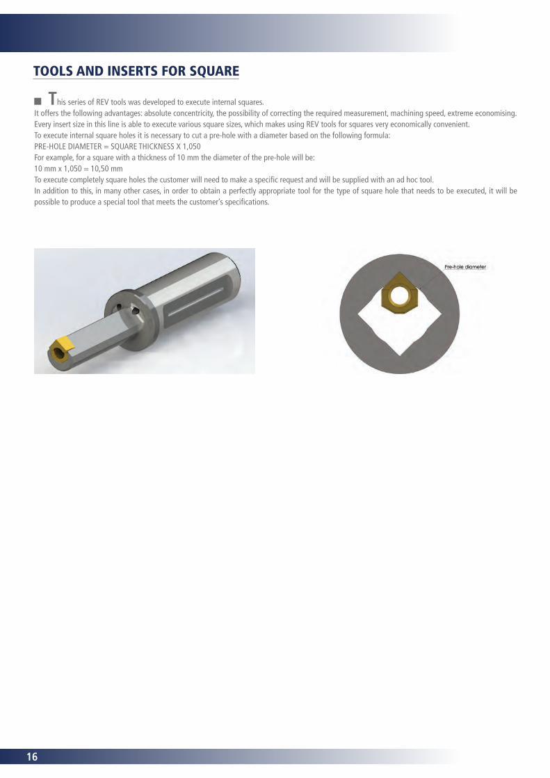
This series of REV tools was developed to execute internal squares.It offers the following advantages: absolute concentricity, the possibility of correcting the required measurement, machining speed, extreme economising.Every insert size in this line is able to execute various square sizes, which makes using REV tools for squares very economically convenient.To execute internal square holes it is necessary to cut a pre-hole with a diameter based on the following formula:PRE-HOLE DIAMETER = SQUARE THICKNESS X 1,050For example, for a square with a thickness of 10 mm the diameter of the pre-hole will be:10 mm x 1,050 = 10,50 mmTo execute completely square holes the customer will need to make a specific request and will be supplied with an ad hoc tool.In addition to this, in many other cases, in order to obtain a perfectly appropriate tool for the type of square hole that needs to be executed, it will be possible to produce a special tool that meets the customer’s specifications.
TOOLS AND INSERTS FOR SQUARE
17
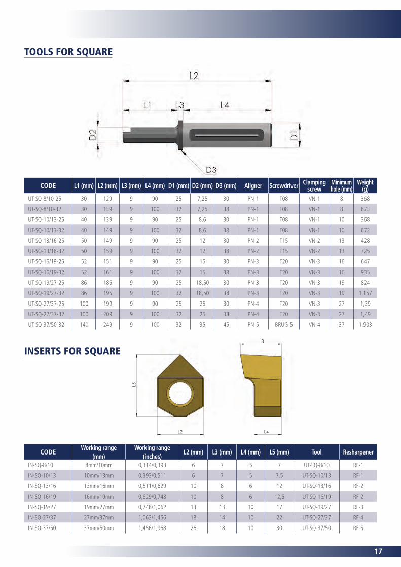
TOOLS FOR SQUARE
CODE Working range
(mm)Working range
(inches)L2 (mm) L3 (mm) L4 (mm) L5 (mm) Tool Resharpener
IN-SQ-8/10 8mm/10mm 0,314/0,393 6 7 5 7 UT-SQ-8/10 RF-1
IN-SQ-10/13 10mm/13mm 0,393/0,511 6 7 5 7,5 UT-SQ-10/13 RF-1
IN-SQ-13/16 13mm/16mm 0,511/0,629 10 8 6 12 UT-SQ-13/16 RF-2
IN-SQ-16/19 16mm/19mm 0,629/0,748 10 8 6 12,5 UT-SQ-16/19 RF-2
IN-SQ-19/27 19mm/27mm 0,748/1,062 13 13 10 17 UT-SQ-19/27 RF-3
IN-SQ-27/37 27mm/37mm 1,062/1,456 18 14 10 22 UT-SQ-27/37 RF-4
IN-SQ-37/50 37mm/50mm 1,456/1,968 26 18 10 30 UT-SQ-37/50 RF-5
L5
L2
L3
L4
INSERTS FOR SQUARE
CODE L1 (mm) L2 (mm) L3 (mm) L4 (mm) D1 (mm) D2 (mm) D3 (mm) Aligner Screwdriver Clamping screw
Minimum hole (mm)
Weight (g)
UT-SQ-8/10-25 30 129 9 90 25 7,25 30 PN-1 T08 VN-1 8 368
UT-SQ-8/10-32 30 139 9 100 32 7,25 38 PN-1 T08 VN-1 8 673
UT-SQ-10/13-25 40 139 9 90 25 8,6 30 PN-1 T08 VN-1 10 368
UT-SQ-10/13-32 40 149 9 100 32 8,6 38 PN-1 T08 VN-1 10 672
UT-SQ-13/16-25 50 149 9 90 25 12 30 PN-2 T15 VN-2 13 428
UT-SQ-13/16-32 50 159 9 100 32 12 38 PN-2 T15 VN-2 13 725
UT-SQ-16/19-25 52 151 9 90 25 15 30 PN-3 T20 VN-3 16 647
UT-SQ-16/19-32 52 161 9 100 32 15 38 PN-3 T20 VN-3 16 935
UT-SQ-19/27-25 86 185 9 90 25 18,50 30 PN-3 T20 VN-3 19 824
UT-SQ-19/27-32 86 195 9 100 32 18,50 38 PN-3 T20 VN-3 19 1,157
UT-SQ-27/37-25 100 199 9 90 25 25 30 PN-4 T20 VN-3 27 1,39
UT-SQ-27/37-32 100 209 9 100 32 25 38 PN-4 T20 VN-3 27 1,49
UT-SQ-37/50-32 140 249 9 100 32 35 45 PN-5 BRUG-5 VN-4 37 1,903
18
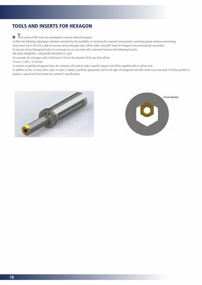
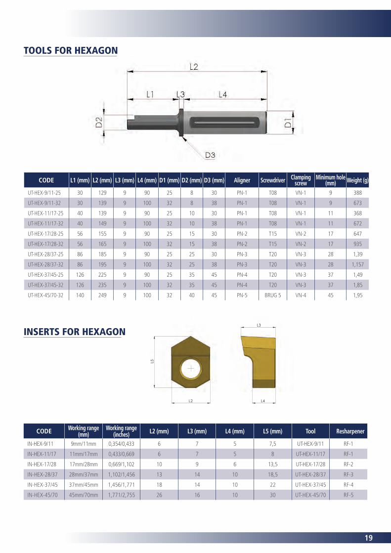
TOOLS AND INSERTS FOR HEXAGON
This series of REV tools was developed to execute internal hexagons.It offers the following advantages: absolute concentricity, the possibility of correcting the required measurement, machining speed, extreme economising.Every insert size in this line is able to execute various hexagon sizes, which makes using REV tools for hexagons very economically convenient.To execute internal hexagonal holes it is necessary to cut a pre-hole with a diameter based on the following formula:PRE-HOLE DIAMETER = HEXAGON THICKNESS X 1,020For example, for a hexagon with a thickness of 10 mm the diameter of the pre-hole will be:10 mm x 1,020 = 10,20 mmTo execute completely hexagonal holes, the customer will need to make a specific request and will be supplied with an ad hoc tool.In addition to this, in many other cases, in order to obtain a perfectly appropriate tool for the type of hexagonal hole that needs to be executed, it will be possible to produce a special tool that meets the customer’s specifications.
19
CODE Working range (mm)
Working range (inches) L2 (mm) L3 (mm) L4 (mm) L5 (mm) Tool Resharpener
IN-HEX-9/11 9mm/11mm 0,354/0,433 6 7 5 7,5 UT-HEX-9/11 RF-1
IN-HEX-11/17 11mm/17mm 0,433/0,669 6 7 5 8 UT-HEX-11/17 RF-1
IN-HEX-17/28 17mm/28mm 0,669/1,102 10 9 6 13,5 UT-HEX-17/28 RF-2
IN-HEX-28/37 28mm/37mm 1,102/1,456 13 14 10 18,5 UT-HEX-28/37 RF-3
IN-HEX-37/45 37mm/45mm 1,456/1,771 18 14 10 22 UT-HEX-37/45 RF-4
IN-HEX-45/70 45mm/70mm 1,771/2,755 26 16 10 30 UT-HEX-45/70 RF-5
CODE L1 (mm) L2 (mm) L3 (mm) L4 (mm) D1 (mm) D2 (mm) D3 (mm) Aligner Screwdriver Clamping screw
Minimum hole (mm) Weight (g)
UT-HEX-9/11-25 30 129 9 90 25 8 30 PN-1 T08 VN-1 9 388
UT-HEX-9/11-32 30 139 9 100 32 8 38 PN-1 T08 VN-1 9 673
UT-HEX-11/17-25 40 139 9 90 25 10 30 PN-1 T08 VN-1 11 368
UT-HEX-11/17-32 40 149 9 100 32 10 38 PN-1 T08 VN-1 11 672
UT-HEX-17/28-25 56 155 9 90 25 15 30 PN-2 T15 VN-2 17 647
UT-HEX-17/28-32 56 165 9 100 32 15 38 PN-2 T15 VN-2 17 935
UT-HEX-28/37-25 86 185 9 90 25 25 30 PN-3 T20 VN-3 28 1,39
UT-HEX-28/37-32 86 195 9 100 32 25 38 PN-3 T20 VN-3 28 1,157
UT-HEX-37/45-25 126 225 9 90 25 35 45 PN-4 T20 VN-3 37 1,49
UT-HEX-37/45-32 126 235 9 100 32 35 45 PN-4 T20 VN-3 37 1,85
UT-HEX-45/70-32 140 249 9 100 32 40 45 PN-5 BRUG 5 VN-4 45 1,95
TOOLS FOR HEXAGON
INSERTS FOR HEXAGON
L5
L2
L3
L4
20
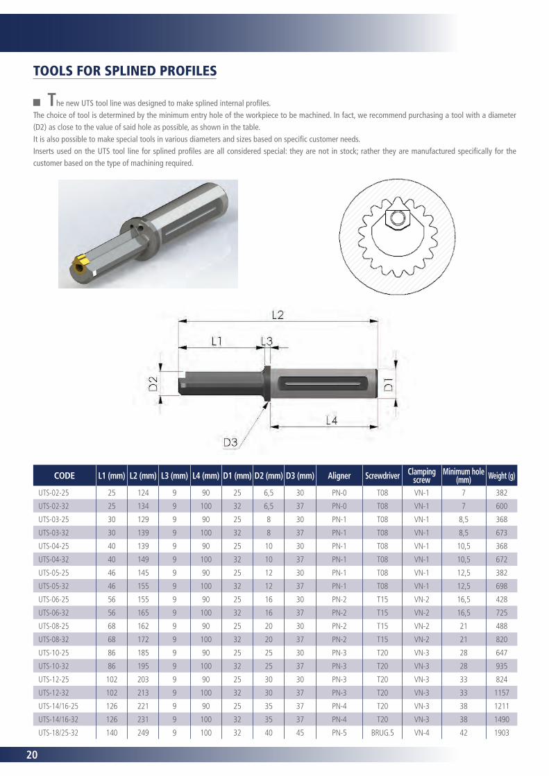
The new UTS tool line was designed to make splined internal profiles. The choice of tool is determined by the minimum entry hole of the workpiece to be machined. In fact, we recommend purchasing a tool with a diameter (D2) as close to the value of said hole as possible, as shown in the table.It is also possible to make special tools in various diameters and sizes based on specific customer needs.Inserts used on the UTS tool line for splined profiles are all considered special: they are not in stock; rather they are manufactured specifically for the customer based on the type of machining required.
CODE L1 (mm) L2 (mm) L3 (mm) L4 (mm) D1 (mm) D2 (mm) D3 (mm) Aligner Screwdriver Clamping screw
Minimum hole (mm) Weight (g)
UTS-02-25 25 124 9 90 25 6,5 30 PN-0 T08 VN-1 7 382
UTS-02-32 25 134 9 100 32 6,5 37 PN-0 T08 VN-1 7 600
UTS-03-25 30 129 9 90 25 8 30 PN-1 T08 VN-1 8,5 368
UTS-03-32 30 139 9 100 32 8 37 PN-1 T08 VN-1 8,5 673
UTS-04-25 40 139 9 90 25 10 30 PN-1 T08 VN-1 10,5 368
UTS-04-32 40 149 9 100 32 10 37 PN-1 T08 VN-1 10,5 672
UTS-05-25 46 145 9 90 25 12 30 PN-1 T08 VN-1 12,5 382
UTS-05-32 46 155 9 100 32 12 37 PN-1 T08 VN-1 12,5 698
UTS-06-25 56 155 9 90 25 16 30 PN-2 T15 VN-2 16,5 428
UTS-06-32 56 165 9 100 32 16 37 PN-2 T15 VN-2 16,5 725
UTS-08-25 68 162 9 90 25 20 30 PN-2 T15 VN-2 21 488
UTS-08-32 68 172 9 100 32 20 37 PN-2 T15 VN-2 21 820
UTS-10-25 86 185 9 90 25 25 30 PN-3 T20 VN-3 28 647
UTS-10-32 86 195 9 100 32 25 37 PN-3 T20 VN-3 28 935
UTS-12-25 102 203 9 90 25 30 30 PN-3 T20 VN-3 33 824
UTS-12-32 102 213 9 100 32 30 37 PN-3 T20 VN-3 33 1157
UTS-14/16-25 126 221 9 90 25 35 37 PN-4 T20 VN-3 38 1211
UTS-14/16-32 126 231 9 100 32 35 37 PN-4 T20 VN-3 38 1490
UTS-18/25-32 140 249 9 100 32 40 45 PN-5 BRUG.5 VN-4 42 1903
TOOLS FOR SPLINED PROFILES
21
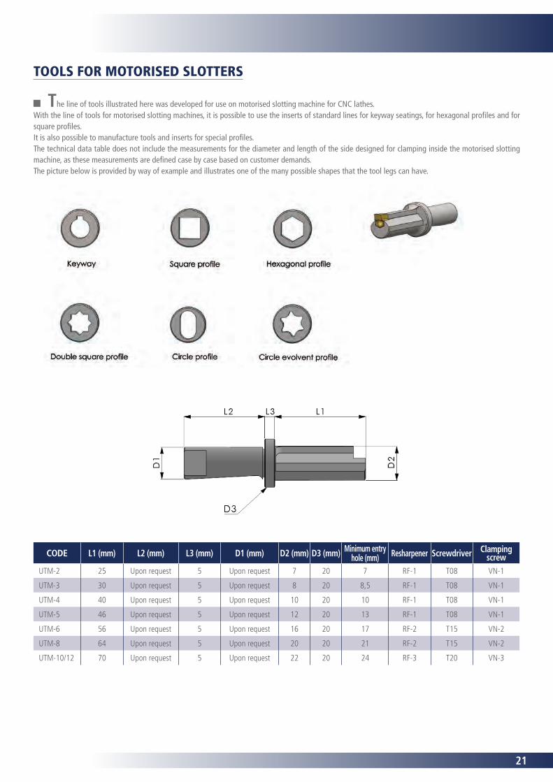
CODE L1 (mm) L2 (mm) L3 (mm) D1 (mm) D2 (mm) D3 (mm) Minimum entry hole (mm) Resharpener Screwdriver Clamping
screwUTM-2 25 Upon request 5 Upon request 7 20 7 RF-1 T08 VN-1
UTM-3 30 Upon request 5 Upon request 8 20 8,5 RF-1 T08 VN-1
UTM-4 40 Upon request 5 Upon request 10 20 10 RF-1 T08 VN-1
UTM-5 46 Upon request 5 Upon request 12 20 13 RF-1 T08 VN-1
UTM-6 56 Upon request 5 Upon request 16 20 17 RF-2 T15 VN-2
UTM-8 64 Upon request 5 Upon request 20 20 21 RF-2 T15 VN-2
UTM-10/12 70 Upon request 5 Upon request 22 20 24 RF-3 T20 VN-3
The line of tools illustrated here was developed for use on motorised slotting machine for CNC lathes.With the line of tools for motorised slotting machines, it is possible to use the inserts of standard lines for keyway seatings, for hexagonal profiles and for square profiles.It is also possible to manufacture tools and inserts for special profiles.The technical data table does not include the measurements for the diameter and length of the side designed for clamping inside the motorised slotting machine, as these measurements are defined case by case based on customer demands.The picture below is provided by way of example and illustrates one of the many possible shapes that the tool legs can have.
TOOLS FOR MOTORISED SLOTTERS
22
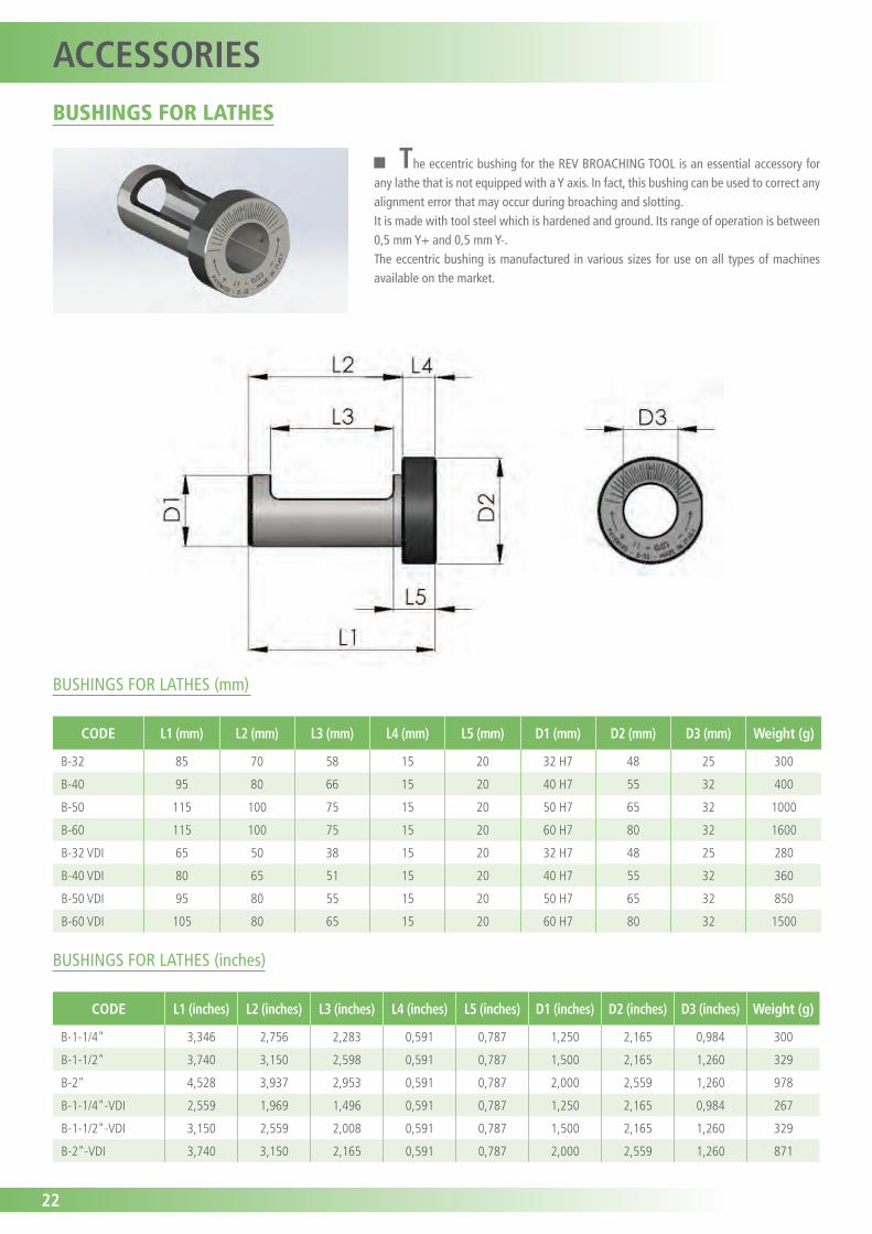
The eccentric bushing for the REV BROACHING TOOL is an essential accessory for any lathe that is not equipped with a Y axis. In fact, this bushing can be used to correct any alignment error that may occur during broaching and slotting.It is made with tool steel which is hardened and ground. Its range of operation is between 0,5 mm Y+ and 0,5 mm Y-.The eccentric bushing is manufactured in various sizes for use on all types of machines available on the market.
CODE L1 (mm) L2 (mm) L3 (mm) L4 (mm) L5 (mm) D1 (mm) D2 (mm) D3 (mm) Weight (g)
B-32 85 70 58 15 20 32 H7 48 25 300
B-40 95 80 66 15 20 40 H7 55 32 400
B-50 115 100 75 15 20 50 H7 65 32 1000
B-60 115 100 75 15 20 60 H7 80 32 1600
B-32 VDI 65 50 38 15 20 32 H7 48 25 280
B-40 VDI 80 65 51 15 20 40 H7 55 32 360
B-50 VDI 95 80 55 15 20 50 H7 65 32 850
B-60 VDI 105 80 65 15 20 60 H7 80 32 1500
CODE L1 (inches) L2 (inches) L3 (inches) L4 (inches) L5 (inches) D1 (inches) D2 (inches) D3 (inches) Weight (g)
B-1-1/4" 3,346 2,756 2,283 0,591 0,787 1,250 2,165 0,984 300
B-1-1/2" 3,740 3,150 2,598 0,591 0,787 1,500 2,165 1,260 329
B-2" 4,528 3,937 2,953 0,591 0,787 2,000 2,559 1,260 978
B-1-1/4"-VDI 2,559 1,969 1,496 0,591 0,787 1,250 2,165 0,984 267
B-1-1/2"-VDI 3,150 2,559 2,008 0,591 0,787 1,500 2,165 1,260 329
B-2"-VDI 3,740 3,150 2,165 0,591 0,787 2,000 2,559 1,260 871
BUSHINGS FOR LATHES (mm)
BUSHINGS FOR LATHES (inches)
BUSHINGS FOR LATHES
ACCESSORIES
23
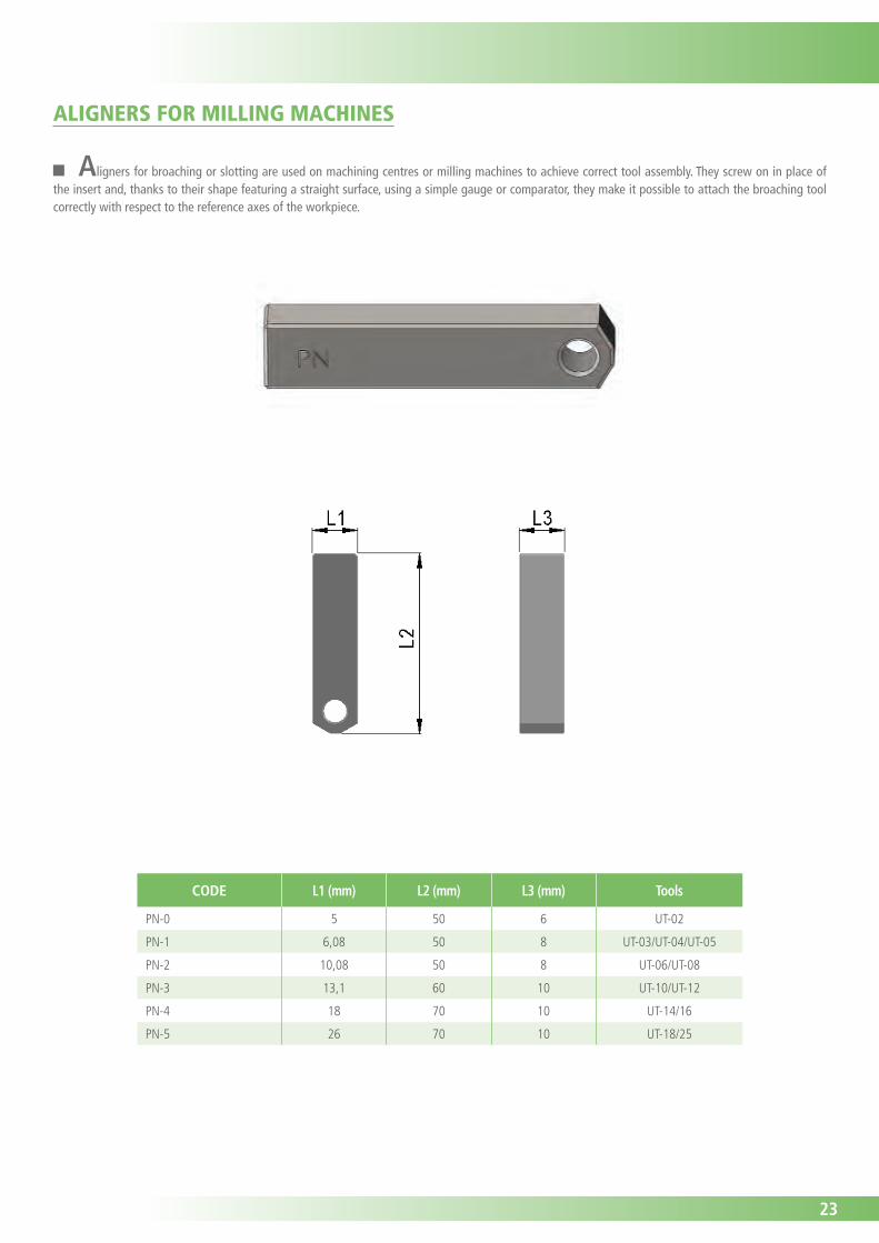
Aligners for broaching or slotting are used on machining centres or milling machines to achieve correct tool assembly. They screw on in place of the insert and, thanks to their shape featuring a straight surface, using a simple gauge or comparator, they make it possible to attach the broaching tool correctly with respect to the reference axes of the workpiece.
CODE L1 (mm) L2 (mm) L3 (mm) Tools
PN-0 5 50 6 UT-02
PN-1 6,08 50 8 UT-03/UT-04/UT-05
PN-2 10,08 50 8 UT-06/UT-08
PN-3 13,1 60 10 UT-10/UT-12
PN-4 18 70 10 UT-14/16
PN-5 26 70 10 UT-18/25
ALIGNERS FOR MILLING MACHINES
24
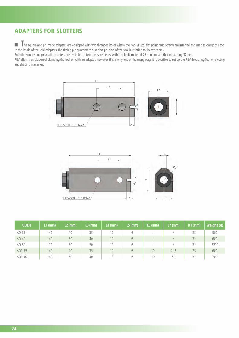
CODE L1 (mm) L2 (mm) L3 (mm) L4 (mm) L5 (mm) L6 (mm) L7 (mm) D1 (mm) Weight (g)
AD-35 140 40 35 10 6 / / 25 500
AD-40 140 50 40 10 6 / / 32 600
AD-50 170 50 50 10 6 / / 32 2200
ADP-35 140 40 35 10 6 10 41,5 25 600
ADP-40 140 50 40 10 6 10 50 32 700
L4
L2
L1
L5
THREADED HOLE 12MA
L3
D1
L4 THREADED HOLE 12 MA
L2
L1
L5
D1
L7
L6
L3
The square and prismatic adapters are equipped with two threaded holes where the two M12x8 flat point grub screws are inserted and used to clamp the tool to the inside of the said adapters. The timing pin guarantees a perfect position of the tool in relation to the work axis.Both the square and prismatic adapters are available in two measurements: with a hole diameter of 25 mm and another measuring 32 mm.REV offers the solution of clamping the tool on with an adapter; however, this is only one of the many ways it is possible to set up the REV Broaching Tool on slotting and shaping machines.
ADAPTERS FOR SLOTTERS
25
HEX 36mm
L2D
2L1
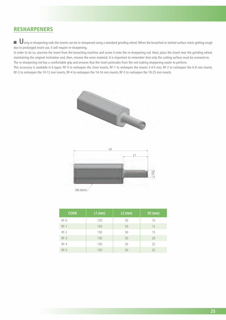
Using re-sharpening rods the inserts can be re-sharpened using a standard grinding wheel. When the broached or slotted surface starts getting rough due to prolonged insert use, it will require re-sharpening.In order to do so, unscrew the insert from the broaching machine and screw it onto the re-sharpening rod. Next, place the insert near the grinding wheel, maintaining the original inclination and, then, remove the worn material. It is important to remember that only the cutting surface must be screwed on.The re-sharpening rod has a comfortable grip and ensures that the insert protrudes from the rod making sharpening easier to perform.This accessory is available in 6 types: RF-0 to resharpen the 2mm inserts, RF-1 to resharpen the inserts 3-4-5 mm, RF-2 to resharpen the 6-8 mm inserts, RF-3 to resharpen the 10-12 mm inserts, RF-4 to resharpen the 14-16 mm inserts, RF-5 to resharpen the 18-25 mm inserts.
CODE L1 (mm) L2 (mm) D2 (mm)
RF-0 150 50 10
RF-1 150 50 12
RF-2 150 50 15
RF-3 150 50 20
RF-4 150 50 25
RF-5 150 50 32
RESHARPENERS
26
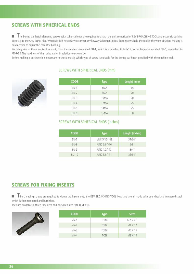
The boring bar hatch clamping screws with spherical ends are required to attach the unit comprised of REV BROACHING TOOL and eccentric bushing perfectly to the CNC lathe. Also, whenever it is necessary to correct any keyway alignment error, these screws hold the tool in the work position, making it much easier to adjust the eccentric bushing.Six categories of them are kept in stock, from the smallest size called BU-1, which is equivalent to M6x15, to the largest one called BU-6, equivalent to M16x30. The hardness of the spring varies in relation to screw size.Before making a purchase it is necessary to check exactly which type of screw is suitable for the boring bar hatch provided with the machine tool.
CODE Type Sizes
VN-1 TORX M2,5 X 8
VN-2 TORX M4 X 10
VN-3 TORX M6 X 15
VN-4 TCEI M8 X 16
CODE Type Lenght (mm)
BU-1 6MA 15
BU-2 8MA 20
BU-3 10MA 20
BU-4 12MA 25
BU-5 14MA 25
BU-6 16MA 30
SCREWS WITH SPHERICAL ENDS (mm)
CODE Type Lenght (inches)
BU-7 UNC 5/16"-18 37/64"
BU-8 UNC 3/8"-16 5/8"
BU-9 UNC 1/2"-13 3/4"
BU-10 UNC 5/8"-11 36/64"
SCREWS WITH SPHERICAL ENDS (inches)
SCREWS WITH SPHERICAL ENDS
SCREWS FOR FIXING INSERTS
The clamping screws are required to clamp the inserts onto the REV BROACHING TOOL head and are all made with quenched and tempered steel, which is then tempered and burnished.They are available in three torx sizes and one Allen size (VN-4) M8x16.
27
CODE Type Hex
T08 TORX 8
T15 TORX 15
T20 TORX 20
HEXAGONAL WRENCH 5 HEX WRENCH FOR TCEI SCREW 5
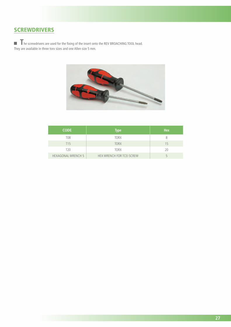
The screwdrivers are used for the fixing of the insert onto the REV BROACHING TOOL head.They are available in three torx sizes and one Allen size 5 mm.
SCREWDRIVERS
28
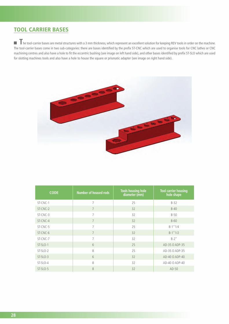
The tool-carrier bases are metal structures with a 3 mm thickness, which represent an excellent solution for keeping REV tools in order on the machine.The tool-carrier bases come in two sub-categories: there are bases identified by the prefix ST-CNC which are used to organise tools for CNC lathes or CNC machining centres and also have a hole to fit the eccentric bushing (see image on left hand side), and other bases identified by prefix ST-SLO which are used for slotting machines tools and also have a hole to house the square or prismatic adapter (see image on right hand side).
CODE Number of housed rods Tools housing hole diameter (mm)
Tool carrier housinghole shape
ST-CNC-1 7 25 B-32
ST-CNC-2 7 32 B-40
ST-CNC-3 7 32 B-50
ST-CNC-4 7 32 B-60
ST-CNC-5 7 25 B-1"1/4
ST-CNC-6 7 32 B-1"1/2
ST-CNC-7 7 32 B-2"
ST-SLO-1 6 25 AD-35 O ADP-35
ST-SLO-2 8 25 AD-35 O ADP-35
ST-SLO-3 6 32 AD-40 O ADP-40
ST-SLO-4 8 32 AD-40 O ADP-40
ST-SLO-5 8 32 AD-50
TOOL CARRIER BASES

29
NOTE

30
NOTE

31
NOTE

THE REVOLUTIONARY TOOLING SYSTEM