mil-c-63550e (ar) 30 september 1985 superseding mil-c
TRANSCRIPT
MIL-C-63550E (AR)30 September 1985SUPERSEDINGMIL-C-63550D (AR)8 July 1983
MILITARY SPECIFICATION
CABLE ASSEMBLIES, ELECTRICAL, FABRICATION SPECIFICATION FOR
This specification is approved for use by the U.S. Army Armament, Munitionsand Chemical Command, Department of the Army, and is available for use by allDepartments and Agencies of the Department of Defense.
1. SCOPE
1.1 Scope. This specification establishes the requirements for manufactureand acceptance of electrical cable assemblies.
2. APPLICABLE DOCUMENTS
2.1 Issues of documents. The following documents of the issue in effect ondate of invitation for bids or request for proposal form a part of this speci-fication to the extent specified herein.
SPECIFICATIONS
MILITARY
MIL-P-116
MIL-P-14232
MIL-C-22520
MIL-I-23053/5
- Preservation, Methods of
- Parts, Equipment and Tools for ArmyMateriel, Packaging and Packing of
- Crimping Tools, Terminal, Hand, WireTermination, General Specification for
- Insulation Sleeving, Electrical, HeatShrinkable, Polyolefin, Flexible,Crosslinked
Beneficial comments (recommendations, additions, deletions) and any pertinentdata which may be of use in improving this document, should be addressed to:Commander, US Army Armament, Munitions and Chemical Command, ATTN:AMSMC-TDA-S(D), Dover, New Jersey 07801-5001 by using the self-addressedStandardization Document Improvement Proposal (DD Form 1426) appearing atthe end of this document or by letter.
FSC 1010
DISTRIBUTION STATEMENT A. Approved for public release; distribution is unlimited.
Downloaded from http://www.everyspec.com

MIL-C-63550E(AR)
MIL-I-23053/8
MIL-C-45662
STANDARDS
MILITARY
MIL-STD-105
MIL-STD-129
MIL-STD-130
MIL-STD-202
MIL-STD-454
MIL-STD-794
MIL-STD-810
- Insulation Sleeving, Electrical, HeatShrinkable, Polvinylidene Fluoride,Semi-Rigid, Crosslinked
- Calibration System Requirements
- Sampling Procedures and Tables forInspection by Attributes
- Marking for Shipment and Storage
- Identification Marking of U.S. Mili-tary Property
- Test Methods for Electronic andElectrical Component Parts
- Standard General Requirements forElectronic Equipment
- Parts and Equipment, Procedures forPackaging and Packing of
- Environmental Test Methods
(Copies of specifications, standards, drawings, and publications required bycontractors in connection with specific procurement functions should beobtained from the procuring activity or as directed by the contractingofficer.)
2.2 Other publications. The following documents form a part of this speci-fication to the extent specified herein. Unless otherwise indicated, theissue in effect on date of invitation for bids or request for proposal shallapply.
AMERICAN SOCIETY FOR TESTING AND MATERIALS (ASTM)
ASTM D 3951 - Standard Practice for CommercialPackaging
(Application for copies should be addressed to the American Society forTesting and Materials, 1916 Race Street, Philadelphia, PA 19103.)
Downloaded from http://www.everyspec.com

MIL-C-63550E(AR)
NATIONAL AEROSPACE STANDARDS
NAS 1747 - Splice, Conductor, Heat Shrinkable,Insulated, Specification for
(Application for copies should be addressed to the National Standards Asso-ciation, Inc., 5161 River Roads Washington$ D.C. 20016.)
(Technical society and technical association specifications and standardsare generally available for reference from libraries. They are also distrib-uted among technical groups and using Federal agencies.)
3. REQUIREMENTS
3.1 Item definition. The electrical cable assemblies specified hereinshall provide electrical interconnection between operating components of theM247 gun system.
3.2 Characteristics.
3.2.1 Performance.
3.2.1.1 Direct-current (dc) resistance. The resistance measured from theconnector contact at one end of a wire to the corresponding contact at theother end (as indicated by the assembly wiring diagram) shall be not greaterthan 5 ohms when tested on a DIT-MCO Model 9100 automatic cable test system ina two-wire measurement mode.
3.2.1.2 Insulation resistance. Unless otherwise specified on applicabledrawings, insulation between connector pins and the assembly connector andbetween isolated circuits shall have a minimum resistance of 100 megohms with500±50 volts direct current (Vdc) applied.
3.2.2 Physical characteristics.
3.2.2.1 Weight. Theweight specified on the applicable assembly drawing.
figure 1 (dimensions U, V, W, X, Y, and Z).
weight of an assembly shall be not greater than the
3.2.2.2 Length. The length of an assembly shall be as shown on the appli-cable assembly drawing. Length measurements shall be made as indicated in
3.2.3 Environmental conditions.
3.2.3.1 Humidity. Each assemblyfound in humid environment with up
shall withstand humidity conditions asto 100 percent relative humidity.
3
Downloaded from http://www.everyspec.com

MIL-C-63550E(AR)
3.2.3.2 Operating temperature. Each assembly shall meet the performancerequirements of 3.2.1 during and after exposure to temperatures within therange of -45° and +52° Celsius (C).
3.2.3.3 Storage temperature. Each assembly shall meet the performancerequirements of 3.2.1 after exposure to ambient air temperature within therange of -50° and +71°C.
3.3 Design and construction.
3.3.1 Production drawings. Each assembly shall be fabricated and assembledin accordance with the applicable assembly drawing. The typical installationdetails of figures 1 through 12 and the requirements of this specificationshall guide fabrication where it is not detailed by the assembly drawing.
3.3.2 Standards of manufacture.
3.3.2.1 Dimensional and angular tolerances. Unless otherwise specified onthe cable assembly drawing, tolerances on length dimensions shall be asfollows:
Length (inches) Tolerance (inches)
0 to 11.99 -0, +1.0012.00 to 71.99 -0, +2.0072.00 and up -0, +3.00
Unless otherwise specified, tolerances on connector clocking to connectorbackshell or boot angles shall be ±15°.
3.3.2.2 Solder requirements. Solder requirements shall be as specified onthe cable assembly drawing.
3.3.2.3 Crimping requirements. Crimp type connector contacts shall becrimped using crimping procedures defined in MIL-C-22520.
3.3.2.4 Shielded wire terminations. Heat shrinkable solder sleeves shallbe used to connect wire shields to the pigtail wires for termination. Theseterminations shall be wired in accordance with the wiring diagram. Thesleeves shall be applied using an Infrared heat gun and shall meet therequirements of NAS 1747. Unterminated shield ends shall be covered with theheat shrinkable tubing shown on drawings and shall extend a minimum of 1/4inch on each side of the shield end. Sleeves shall be placed not further than3 inches from the rear of the connector grommet on connectors with straightbackshells and 4 inches from the rear of the connector grommet on connectorswith 45° or 90° backshells. The sleeves shall be staggered so that the wirebundle remains at a minimum. Each shield shall be trimmed and sealed toeliminate any frayed ends prior to installing sleeves on tubing.
4
Downloaded from http://www.everyspec.com

MIL-C-63550E(AR)
Figure 1. Composite cable assembly.
5
Downloaded from http://www.everyspec.com

MIL-C-63550E(AR)
Figure 2. Cable termination (without EMP shielding).
6
Downloaded from http://www.everyspec.com

MIL-C-63550E(AR)
Figure 3. Cable termination (with EMP shielding).
7
Downloaded from http://www.everyspec.com

MIL-C-63550E(AR)
Figure 4. Method of starting and finishing wrap on harness branchesof transition where heat sealable tape is specified.
8
Downloaded from http://www.everyspec.com

MIL-C-63550E(AR)
Figure 6. Cable transition (with EMP shielding).
9
Downloaded from http://www.everyspec.com

MIL-C-63550E(AR)
Figure 5. Cable transition (without EMP shielding).
10
Downloaded from http://www.everyspec.com
MIL-C-63550E(AR)
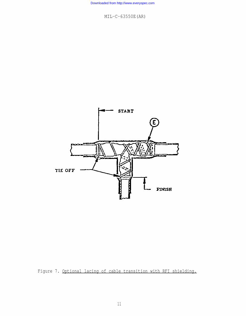
Figure 7. Optional lacing of cable transition with RFI shielding.
11
Downloaded from http://www.everyspec.com

MIL-C-63550E(AR)
Figure 8. Steps for sealing transition crotch, usingheat sealable tape (25 mil).
12
Downloaded from http://www.everyspec.com

MIL-C-63550E(AR)
Figure 9. Typical transition indicated on assembly drawings.
Downloaded from http://www.everyspec.com
MIL-C-63550E(AR)
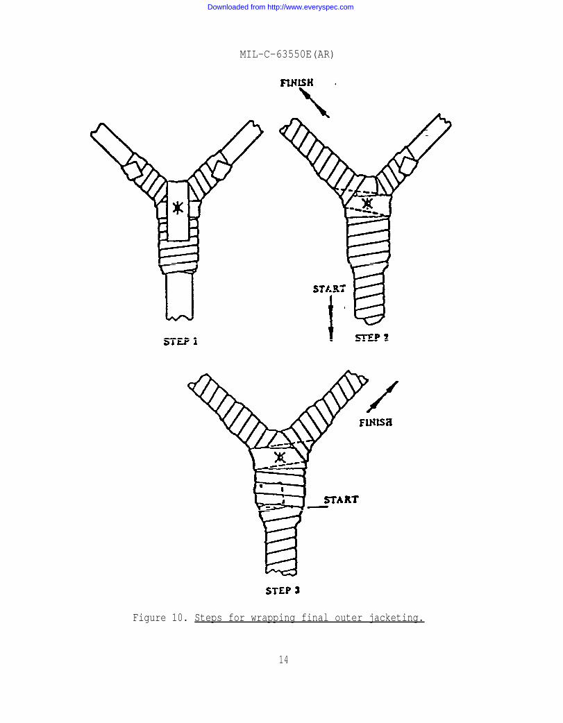
Figure 10. Steps for wrapping final outer jacketing.
14
Downloaded from http://www.everyspec.com
MIL-C-63550E(AR)
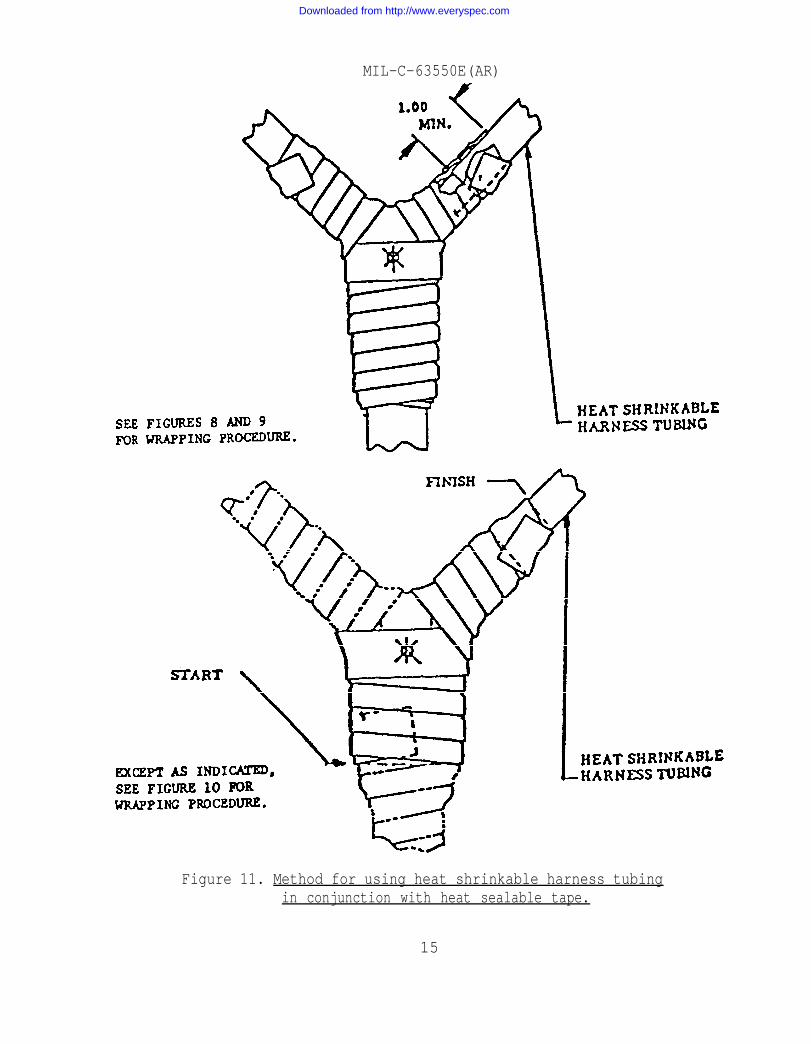
Figure 11. Method for using heat shrinkable harness tubingin conjunction with heat sealable tape.
15
Downloaded from http://www.everyspec.com

MIL-C-63550E(AR)
Figure 12. Interpretation of connector key or keyway location.
16
Downloaded from http://www.everyspec.com

MIL-C-63550E(AR)
3.3.2.5 Cable jacketing. (See 6.3.1.) All cables shall be covered withthe jacketing specified on the assembly drawing. Heat-sealable tape shall bewrapped with a minimum of 50 percent overlap, forming a water-resistant cover-ing. Heat-sealable tape shall be tightly wrapped to keep cable diameters to aminimum (see figure 4). Jacketing shall extend into the boot or transition atleast to the dimensions shown in figures 2, 3, 5, 6, 7, 9, and 11. Multiplesections of heat-shrinkable tubing may be used in long harness branches, pro-vided each individual length is at least 36 inches long. In each case, a min-imum of 2 inches of overlapping tubing shall be required. Bonding of jacketjoints to their mating parts shall be required. This bond shall provide awater-resistant join. Excess adhesive on the outside of the harness jacket-ing shall be removed. Heat-shrinkable tubing shall be uniformly shrunk tominimum diameters determined by the bundle size and shall be water-resistant,with no cracks, splits, or abrasions. Heat-sealable tape shall be cured in ahot air oven until it reaches its melting point of ±145° ±10°C; cure timerequired to achieve melting is typically 90 minutes.
3.3.2.6 EMP shielding. When specified on the cable assembly drawing, tubu-lar EMP shielding shall be installed over the wire bundle and under the cablejacketing. At each point where a piece of shielding ends, the shield shall betrimmed and sealed to eliminate frayed ends. A layer of cable jacketingextending 1 inch on each end of the shield shall be applied between the wirebundle and the shield. Each cable branch shall contain one continuous pieceof shield. Shields shall not be spliced. Shielding tape wrap shall be usedat transition points and shall overlap the EMP tubular shielding to the “Y”dimension given in figure 6. Shielding tape wrap shall be held in place usingeither of the methods shown in figures 6 and 7.
3.3.2.7 Cable terminations. Cable terminations shall be as shown in figure2 or 3. Other methods shall be as detailed on the cable assembly drawing.Boots, jacketing, and feed-through seals shall be bonded to mating parts withadhesive unless parts are supplied with adhesive coating. Boots, jacketing,and feed-through seals shall be fully recovered and water-resistant, with nocracks, splits, or abrasions. Backshells shall be torqued as specified intable 1. Unless otherwise specified, all unused contact locations shall befilled with contacts and all unused grommet feed-through holes shall beplugged with the plugs supplied with the connector.
3.3.2.8 Cable transitions. Cable transitions shall be as shown in figures5, 6, 7, 9, and 11. On cables using heat sealable tape transitions, thetransition shall be wrapped before the harness branches are wrapped. Wheretape transitions are used with heat shrinkable tubing, the tubing shall beinstalled first.
3.3.2.9 Adhesives. Adhesive application processes shall conform to adhe-sive manufacturer’s specifications.
17
Downloaded from http://www.everyspec.com

MIL-C-63550E(AR)
TABLE I. Adapter nut torque.
Torquerequired
Shell size (in/lb)
08 35/4010 40/4512 50/5514 65/7516 65/7518 80/8520 90/9522 100/11024 120/13028 130/14032 150/16036 175/18540 190/200
3.3.3 Cable markings. Markings identified in 3.3.3.2 shall be applied onsleeving conforming to MIL-I-23053/5 or equivalent by typing with black char-acter. The marking shall be arranged and located in accordance with thecable assembly drawing.
3.3.3.1 Marking protection. All marking shall be covered with clearsleeving conforming to MIL-I-23053/8, or equivalent.
3.3.3.2 Cable identification. Each cable shall be identified in accordancewith MIL-STD-130. The marking shall include the design activity FSCM, theabbreviation ASSY, the part number, the manufacturer's FSCM and the cablereference designation.
3.3,3.3 Termination Identification. Each termination, connector, lug, etc.,shall be identified with the applicable reference designation.
3.3.4 Age control. The assembly and earliest cure dates (in quarter andyear) of any synthetic age-sensitive elastomer installed within the cableassembly shall be indelibly affixed to the cable assembly. All age-sensitiveelastomers shall be installed in the cable assembly withinthe cure date.
3.3.5 Workmanship. The assembly shall be in accordanceship requirements of MIL-STD-454, requirement 9.
8 quarters after
with the workman-
18
Downloaded from http://www.everyspec.com

MIL-C-63550E(AR)
3.3.5.1 Insulation stripping. Removal of insulation from electrical wireconductors, 12 AWG and smaller, and from outer jackets of shielded cablesshall be performed so that there is no evidence of physical damage to theindividual wire or braided strands.
4. QUALITY ASSURANCE PROVISIONS
4.1 Responsibility for inspection. Unless otherwise specified in the con-tract or purchase order, the contractor is responsible for the performance ofall the quality assurance provisions specified in section 4 to determine con-formance to the requirements of sections 3 and 5. Except as otherwise speci-fied, the contractor may utilize his own facilities or any commercial labora-tory-acceptable to the procuring activity (see 6.2). The procuring activityreserves the right to perform or witness any of the inspections set forth inthis document where such inspections are deemed necessary to assure suppliesand services conform to prescribed requirements. The contractor will not berestricted to the inspections or the methods of inspection defined herein,provided that an equivalent control, approved by the procuring activity, isutilized.
4.1.1 Inspection equipment. Unless otherwise specified in the contract.the contractor is responsible for the provisions and maintenance of allinspection and test equipment necessary to assure that supplies and servicesconform to contract requirements. Commercial, modified commercial, orcontractor-designed inspection equipment or measuring setups must be capableof repetitive measurements to an accuracy of 10 percent of the componenttolerance. Calibration of inspection and test equipment shall be in accor-dance with MIL-C-45662. Where compliance with MIL-C-45662 is not possible,special calibration requirements shall be prepared for approval by the pro-curing activity.
4.1.2 Special tests and examinations. Special tests and examinations (see6.3), when required, shall be performed in accordance with tables II and III.The inspection sequence shall be in accordance with table II.
Note: Assemblies subjected to special tests and examina-tions shall not be used for any other purposes andshall be indelibly marked, DO NOT USE.
4.1.2.1 Preproduction. If required by the procuring activity (see 6.2),two assemblies shall be inspected by the contractor at a location approved bythe procuring activity.
4.1.2.1.1 Preproduction failure. Failure of a preproduction assembly tomeet the requirements specified herein shall be cause for cessation of inspec-tion. When corrective measures satisfactory to the procuring activity havebeen taken, inspection may be continued.
19
Downloaded from http://www.everyspec.com

MIL-C-63550E(AR)
TABLE II. Sequence of special tests and examinations.
Test sequence
Design and construction
Physical characteristics
Performance
Humidity
Low temperature
High temperature
Storage temperature
Packaging
Paragraphnumber
4.3
4.2.2
4.2.1
4.2.3.1
4.2.3.2.1
4.2.3.2.2
4.2.3.3
4.4.
Prepr-ductionsample
1
x
x
x
x
x
x
x
x
2
x
x
x
x
x
x
x
x
Initialproductionsample
1
x
x
x
x
x
x
x
x
2
x
x
x
x
x
x
x
x
4.1.2.2 Initial production. Unless otherwise specified, the procuringactivity shall select two assemblies from the first 10 assemblies producedunder a production contract (see 6.2). Once verification and validation ofcompliance with the requirement has been accomplished, quality conformanceinspection of the remainder of the production contract shall be as specified(see 4.2).
4.1.2.2.1 Initial production failure. Failure of an initial productionassembly during or as a result of initial production inspection shall be causefor rejection of the assembly. The procuring activity shall refuse acceptanceof production assemblies until evidence of corrective action is provided.
20
Downloaded from http://www.everyspec.com

MIL-C-63550E(AR)
TABLE III. Preproduction, initial production, and quality
Description
PerformanceDC resistanceInsulationresistance
PhysicalcharacteristicsWeightLength
EnvironmentalconditionsHumidityOperatingtemperatureLow temper-atureHigh tem-perature
Storage tem-perature
Design andconstructionProductiondrawings
Standards ofmanufacture
Cable markingsAge Control
conformance inspections.
Quality confor-mance inspection
Require-ment
3.2.13.2.1.1
3.2.1.2
3.2.23.2.2.13.2.2.2
3.2.33.2.3.1
3.2.3.2
3.2.3.3
3.3
3.3.1
3.3.23.3.33.3.4
Method
4.2.14.2.1.1
4.2.1.2
.4.2.24.2.2.14.2.2.2
4.2.34.2.3.1
4.2.3.2
4.2.3.2.1
4.2.3.2.2
4.2.3.3
4.3
4.3.1
4.3.24.3.34.3.4
Specialtests andexaminations
Pre-prod
x
x
xx
x
x
x
x
x
xxx
Initialprod
x
x
xx
x
x
x
x
x
xxx
Classification ofcharacteristics
Crit-ical Major Minor
100%
100%
100% (See note.)
2.5
4.04.06.5
21
Downloaded from http://www.everyspec.com
MIL-C-63550E(AR)
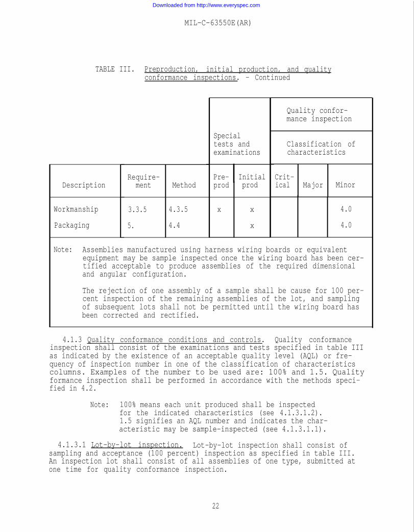
TABLE III. Preproduction, initial production, and qualityconformance inspections. - Continued
Description
Workmanship
Packaging
Require-ment Method
3.3.5 4.3.5
5. 4.4
Specialtests andexaminations
Pre- Initialprod prod
x x
x
Quality confor-mance inspection
Classification ofcharacteristics
Crit-ical Major Minor
4.0
4.0
Note: Assemblies manufactured using harness wiring boards or equivalentequipment may be sample inspected once the wiring board has been cer-tified acceptable to produce assemblies of the required dimensionaland angular configuration.
The rejection of one assembly of a sample shall be cause for 100 per-cent inspection of the remaining assemblies of the lot, and samplingof subsequent lots shall not be permitted until the wiring board hasbeen corrected and rectified.
4.1.3 Quality conformance conditions and controls. Quality conformanceinspection shall consist of the examinations and tests specified in table IIIas indicated by the existence of an acceptable quality level (AQL) or fre-quency of inspection number in one of the classification of characteristicscolumns. Examples of the number to be used are: 100% and 1.5. Qualityformance inspection shall be performed in accordance with the methods speci-fied in 4.2.
Note: 100% means each unit produced shall be inspectedfor the indicated characteristics (see 4.1.3.1.2).1.5 signifies an AQL number and indicates the char-acteristic may be sample-inspected (see 4.1.3.1.1).
4.1.3.1 Lot-by-lot inspection. Lot-by-lot inspection shall consist ofsampling and acceptance (100 percent) inspection as specified in table III.An inspection lot shall consist of all assemblies of one type, submitted atone time for quality conformance inspection.
22
Downloaded from http://www.everyspec.com

MIL-C-63550E(AR)
4.1.3.1.1 Sampling.dance with MIL-STD-105
Sampling and inspection shall be conducted in accor-on the basis of percent defective for those character-
istics of table III assigned an AQL. Except as specifically designated intable III, characteristics having the same AQL shall be treated as a group.
4.1.3.1.1.1 AQL validation. Before sampling can commence for any produc-tion contract, a minimum of 20 assemblies shall be subjected to 100 percentinspection to-verify conformance to requirements listed in table III. Processaverage for each requirement shall be computed as specified below. If thecomputed process average for the requirements exceeds the specified AQL, 100percent inspection shall be continued until the process average for 20 con-secutive assemblies is less than the specified AQL.
Process average = Number of defectivesNumber of assemblies inspected x 100
4.1.3.1.1.2 Sampling failures. Rejected assemblies or lots shall be pro-cessed in accordance with the acceptance and rejection criteria of MIL-STD-105.
4.1.3.1.2 Acceptance (100 percent) inspection. For the requirements speci-fied for acceptance (100 percent) inspection in table III, each assembly ofthe inspection lot shall be subjected to the tests specified therein. Inspec-tion shall be performed by the contractor at the place of manufacture, exceptas specified in 4.1.
4.1.3.1.2.1 Acceptance (100 percent) inspection failures. Any assemblythat fails to conform to any acceptance (100 percent) inspection shall berejected. The rejected assembly may be repaired or corrected and resubmittedfor inspection.
4.1.4 Test methods.
4,1.4.1 Test conditions. Unless otherwise specified, all tests shall beconducted under the following conditions:
Air temperature: +23° ±10°C.
Barometric pressure: 28.5 +2.0,-4.5 inches of mercury.
Relative humidity: 50 ±30 percent.
4.1.4.2 Test equipment. The test equipment used in the performance of theexaminations and tests specified herein shall be in accordance with 4.1.1.
4.2 Quality conformance inspection.
4.2.1 Performance.
4.2.1.1 DC resistance. The assembly shall be tested in accordance withMIL-STD-202, method 303, to verify conformance to 3.2.1.1.
23
Downloaded from http://www.everyspec.com

MIL-C-63550E(AR)
4.2.1.2 Insulation resistance. The assemblywith MIL-STD-202, method 302, test condition B,Measurements may be taken prior to the 2-minuteinsulation resistance meets the specified limit
4.2.2 Physical characteristics.
shall be tested in accordanceto verify conformance to 3.2.1.2.electrification time if theand is steady or increasing.
4.2.2.1 Weight. The assembly shall be weighed to verify conformance to3.2.2.1, using commercially available scales accurate to the limits of 4.1.1.
4.2.2.2 Length. The assembly shall be inspected dimensionally to verifyconformance to 3.2.2.2.
4.2.3 Environmental verifications methods. Environmental verificationtesting shall be conducted in accordance with detailed test procedures pre-pared by the contractor and approved by the procuring activity. Testingmethods incorporated in these test procedures shall be in accordance with thetest methods delineated herein.
a. The assemblies undergoing the special tests and examin-ations of table III shall be subjected to performancetests before, during (where required in the testmethod), and after each environmental test performed.
b. Assemblies undergoing the quality conformance inspec-tions of table III shall have passed the acceptancetests indicated therein. After all environmentaltests have been completed, the assemblies shall betested only once for the postenvironmental performancetests specified.
4.2.3.1 Humidity. The assembly shall be subjected to humidity in accor-dance with MIL-STD-810, method 507.1, procedure IV, to verify conformance to3.2.3.1. During humidity exposure, the assembly shall be subjected to theperformance tests of 4.2.1.
4.2.3.2 Operating temperature.
4.2.3.2.1 Low temperature. The assembly shall be subjected to low tempera-ture in accordance with MIL-STD-810, method 502.1, procedure I, to verifyconformance to 3.2.3.2. The temperature shall be maintained at -45°C for 24hours.
At the conclusion of this time, the assembly shall be stabilized at -32°C andbe subjected to the performance tests of 4.2.1. Then the assembly shall bereturned to +23° ±10°C and again subjected to the performance tests of 4.2.1.
24
Downloaded from http://www.everyspec.com

MIL-C-63550E(AR)
4.2.3.2.2 High temperature. The assembly shall be subjected to high tem-perature in accordance with MIL-STD-810, method 501.1, procedure I, to verifyconformance to 3.2.3.2. The temperature shall be maintained at +71°C for 48hours. At the conclusion of this time, the assembly shall be stabilized at+52°C and subjected to the performance tests of 4.2.1. Then the assemblyshall be returned to +23° ±10°C and again subjected to the performance testsof 4.2.1.
4.2.3.3 Storage temperature. The assembly shall be tested in conjunctionwith the tests of 4.2.3.2.1 and 4.2.3.2.2 to verify conformance to 3.2.3.3.
4.3 Design and construction.
4.3.1 Production drawings. Visual examination shall be performed duringfabrication and assembly to verify conformance to the drawing set and 3.3.1.
4.3.2 Standards of manufacture. A visual examination shall be performed atall phases of manufacture to verify continued conformance to the standards ofmanufacture specified in 3.3.2.
4.3.3 Cable markings. Each cable assembly shall be inspected to verifycompliance to 3.3.3.
4.3.4 Verification of age control. Visual examination shall be conductedto verify conformance to 3.3.4. The contractor shall provide certification oftraceability attesting to the designated cure dates.
4.3.5 Workmanship. Workmanship examination shall be performed at allphases of fabrication, assembly, and test and shall be in accordance withMIL-STD-454, requirement 9, to verify conformance to 3.3.5.
4.4 Preparation for delivery. The assembly shall be inspected by the con-tractor prior to shipment to ensure conformance to the preservation, packaging,packing, and marking requirements in section 5. Sampling inspections shall belimited to those characteristics that can be determined by visual examination.
5. PACKAGING
5.1 Preservation and packing. Packaging levels and methods shall be suchas to ensure protection of the assembly against natural and induced environ-ments. Packaging levels (A, B, and C) are defined in MIL-STD-794 and packag-ing methods are defined in MIL-P-116.
5.1.1 Level A. For level A (long-term storage), the assembly shall be pre-served and packed in accordance with MIL-P-116, methods II, IA, or IC, andwith the applicable packaging data sheet (AMC Form 1029) provided by the pro-curing activity. Container shall be in compliance with MIL-STD-794 and shallprovide adequate protection against corrosion, deterioration, and damageduring handling, shipment, and storage.
25
Downloaded from http://www.everyspec.com

MIL-C-63550E(AR)
5.1.2 Level B. For level B (intermediate-term storage), the assembly shallbe preserved and packed as for level A, except that methods and materialsshall be as specified in MIL-P-14232.
5.1.3 Level C. For level C (immediate use upon delivery), the asssemblyshall be preserved and packed in accordance with industrial packaging prac-tices and ASTM D 3951. Packages which require overpacking for acceptance bycommon carrier shall be overpacked in uniform quantities in a manner to ensurecarrier acceptance at the lowest freight rates and to ensure safe deliveryfrom the supply source to the first receiving activity.
5.1.4 Data requirements. The contractor shall prepare packaging data forlevel A only, as follows:
a. Additional packaging information not presented on thecable assembly drawing but essential to completenessof packaging data.
b. Packaging procedures as required by MIL-STD-794.These procedures shall provide for adequate protectionagainst corrosion, deterioration, and damage duringshipment.
5.2 Marking. Each inner and outer container shall be marked in accordancewith MIL-STD-129 and the following:
a. Part number.
b. Nomenclature.
c. Quantity.
d. Purchase order/contract number.
e. Serial number.
f. Date of manufacture.
6. NOTES
6.1 Intended use. The cable assemblies are intended to provide electricalinterconnection between operating components of the M247 gun system. Eachcable assembly will provide environmental, mechanical, and EMP protection forindividual electrical wiring. The connectors on each assembly are keyed tominimize the possibility of improperly mating cables to equipment.
26
Downloaded from http://www.everyspec.com

MIL-C-63550E(AR)
6.2 Ordering data. Procurement documents should specify the following:
a. Title, number, and date of this specification.
b. Special tests and examinations:
(1)
(2)
(3)
Preproduction. (See 6.3a.) If required for pro-curement, specific request should be included inthe purchase order or contract (see 4.1.2.1).
Initial production. (See 6.3b.) If not requiredfor procurement, specific direction to eliminatethese inspections should be included in the pur-chase order or contract (see 4.1.2.2).
Activity and facility responsible for specialtests and examinations. (See 4.1.) The purchaseorder or contract should specify the name of theactivity and the facility responsible for specialtests and examinations.
c. Applicable levels of packaging and packing and markinginstructions (see 5.1 and 5.2).
6.3 Definitions. The following definitions explain the tests specifiedherein and when the tests are to be run:
a. Preproduction. These inspections verify a contrac-tor’s capability to produce a component to a specifi-cation and/or drawing set. The component may be builton a prototype basis without the use of productiontooling. Preproduction tests will normally be con-ducted whenever a new contractor is selected.
b. Initial production. These inspections verify theproduction tooling, methods, and processes used tomanufacture a component. They are required onselected first articles produced in a production runand should be repeated once every 3 years oncontinuing contracts.
c. Quality conformance inspection.
(1) Sampling. These inspections verify that physicaland configuration characteristics are maintainedduring the production run.
Downloaded from http://www.everyspec.com
MIL-C-63550E(AR)
(2) Acceptance. These inspections are performed oneach manufactured assembly to verify its func-tional performance against specificationrequirements.
6.3.1 Cable jacketing. Cable jacketing is defined as the exteriorelastomeric cable cover which accounts for the assembly’s fluid resistancecapability. This elastomeric jacketing includes, but is not limited to,heat shrinkable tubing, heat sealable tape, boots, transitions, etc.
6.3.2 Previous Issues. MIL-C-63550 (AR) and associated amendments were forUS Army Armament Research and Development Center for internal use only andwere not forwarded to the Naval Publications and Forms Center for publication.
Custodian:Army-AR
Preparing Activity:Army-AR
Project No. 1010-A131
28
Downloaded from http://www.everyspec.com

Downloaded from http://www.everyspec.com

Downloaded from http://www.everyspec.com