miniature din-sized (48 x 48 mm) quartz timer with ... · csm_h5cn_ds_e_4_2 1 digital timer h5cn...
TRANSCRIPT

CSM_H5CN_DS_E_4_2
1
Digital Timer
H5CNMiniature DIN-sized (48 x 48 mm) Quartz Timer with Abundant Series Versions• Series version cover a wide range of rated times; 9.999 s,
99.99 s, 999.9 s, 99 min 59 s, and 99 hrs 59 min.• Selection of elapsed time indication, remaining time indication,
contact output, and transistor output types to suit requirements.• Power supply freely selectable within a range of 100 to
240 VAC, as well as 12 to 48 VDC.
The new models manufactured in April 2014 or after will be changed to use internal non-volatile memory for memory backup. A Backup Battery (Y92S-20) for memory backup is not required for the new models.
Refer to Safety Precautions for All Timers.Refer to Safety Precautions on page 12
For the most recent information on models that have been certified for safety standards, refer to your OMRON website.
Model Number Structure
■ Model Number LegendNote: This model number legend includes combinations that are not available. Before ordering, please check the List of Models on page 2 for
availability.
1. DisplayX:UP display (increments from 0 to the set time)Y:DOWN display (decrements from the set time to 0)
2. Rated timeZ: 0.001 to 9.999 sA:0.001 to 99.99 sB:0.1 to 999.9 sC:1 s to 99 min 59 sD:1 min to 99 h 59 min
3. Output modeN: N mode (Power ON-delay)
4. Memory backupNone: Not providedM: Provided
5. Output typeNone: Contact output (SPDT)S: Transistor output
21 3 4 5H5CN- @@N@@
H5CN
2
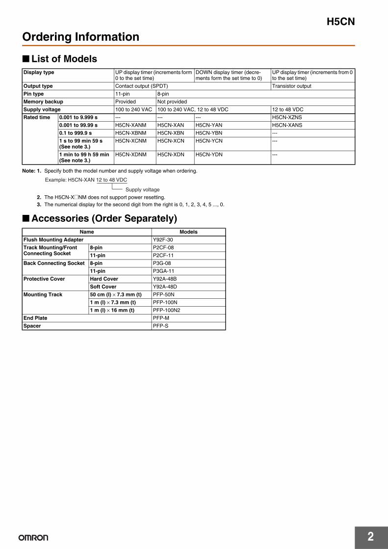
Ordering Information
■ List of Models
Note: 1. Specify both the model number and supply voltage when ordering.
2. The H5CN-X@NM does not support power resetting.3. The numerical display for the second digit from the right is 0, 1, 2, 3, 4, 5 ..., 0.
■ Accessories (Order Separately)
Display type UP display timer (increments form 0 to the set time)
DOWN display timer (decre-ments form the set time to 0)
UP display timer (increments from 0 to the set time)
Output type Contact output (SPDT) Transistor outputPin type 11-pin 8-pinMemory backup Provided Not providedSupply voltage 100 to 240 VAC 100 to 240 VAC, 12 to 48 VDC 12 to 48 VDCRated time 0.001 to 9.999 s --- --- --- H5CN-XZNS
0.001 to 99.99 s H5CN-XANM H5CN-XAN H5CN-YAN H5CN-XANS0.1 to 999.9 s H5CN-XBNM H5CN-XBN H5CN-YBN ---1 s to 99 min 59 s (See note 3.)
H5CN-XCNM H5CN-XCN H5CN-YCN ---
1 min to 99 h 59 min (See note 3.)
H5CN-XDNM H5CN-XDN H5CN-YDN ---
Supply voltage
Example: H5CN-XAN 12 to 48 VDC
Name ModelsFlush Mounting Adapter Y92F-30Track Mounting/Front Connecting Socket
8-pin P2CF-0811-pin P2CF-11
Back Connecting Socket 8-pin P3G-0811-pin P3GA-11
Protective Cover Hard Cover Y92A-48BSoft Cover Y92A-48D
Mounting Track 50 cm (I) × 7.3 mm (t) PFP-50N1 m (I) × 7.3 mm (t) PFP-100N1 m (I) × 16 mm (t) PFP-100N2
End Plate PFP-MSpacer PFP-S
H5CN
3
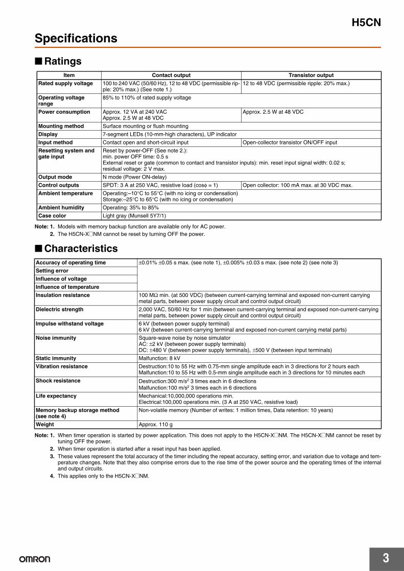
Specifications
■ Ratings
Note: 1. Models with memory backup function are available only for AC power.2. The H5CN-X@NM cannot be reset by turning OFF the power.
■ Characteristics
Note: 1. When timer operation is started by power application. This does not apply to the H5CN-X@NM. The H5CN-X@NM cannot be reset bytuning OFF the power.
2. When timer operation is started after a reset input has been applied.3. These values represent the total accuracy of the timer including the repeat accuracy, setting error, and variation due to voltage and tem-
perature changes. Note that they also comprise errors due to the rise time of the power source and the operating times of the internaland output circuits.
4. This applies only to the H5CN-X@NM.
Item Contact output Transistor outputRated supply voltage 100 to 240 VAC (50/60 Hz), 12 to 48 VDC (permissible rip-
ple: 20% max.) (See note 1.)12 to 48 VDC (permissible ripple: 20% max.)
Operating voltage range
85% to 110% of rated supply voltage
Power consumption Approx. 12 VA at 240 VACApprox. 2.5 W at 48 VDC
Approx. 2.5 W at 48 VDC
Mounting method Surface mounting or flush mountingDisplay 7-segment LEDs (10-mm-high characters), UP indicatorInput method Contact open and short-circuit input Open-collector transistor ON/OFF inputResetting system and gate input
Reset by power-OFF (See note 2.):min. power OFF time: 0.5 sExternal reset or gate (common to contact and transistor inputs): min. reset input signal width: 0.02 s; residual voltage: 2 V max.
Output mode N mode (Power ON-delay)Control outputs SPDT: 3 A at 250 VAC, resistive load (cosφ = 1) Open collector: 100 mA max. at 30 VDC max.Ambient temperature Operating:–10°C to 55°C (with no icing or condensation)
Storage:–25°C to 65°C (with no icing or condensation)Ambient humidity Operating: 35% to 85%Case color Light gray (Munsell 5Y7/1)
Accuracy of operating time ±0.01% ±0.05 s max. (see note 1), ±0.005% ±0.03 s max. (see note 2) (see note 3)Setting errorInfluence of voltageInfluence of temperatureInsulation resistance 100 MΩ min. (at 500 VDC) (between current-carrying terminal and exposed non-current carrying
metal parts, between power supply circuit and control output circuit)Dielectric strength 2,000 VAC, 50/60 Hz for 1 min (between current-carrying terminal and exposed non-current-carrying
metal parts, between power supply circuit and control output circuit)Impulse withstand voltage 6 kV (between power supply terminal)
6 kV (between current-carrying terminal and exposed non-current carrying metal parts)Noise immunity Square-wave noise by noise simulator
AC: ±2 kV (between power supply terminals)DC: ±480 V (between power supply terminals), ±500 V (between input terminals)
Static immunity Malfunction: 8 kVVibration resistance Destruction:10 to 55 Hz with 0.75-mm single amplitude each in 3 directions for 2 hours each
Malfunction:10 to 55 Hz with 0.5-mm single amplitude each in 3 directions for 10 minutes eachShock resistance Destruction:300 m/s2 3 times each in 6 directions
Malfunction:100 m/s2 3 times each in 6 directionsLife expectancy Mechanical:10,000,000 operations min.
Electrical:100,000 operations min. (3 A at 250 VAC, resistive load)Memory backup storage method (see note 4)
Non-volatile memory (Number of writes: 1 million times, Data retention: 10 years)
Weight Approx. 110 g
H5CN
4
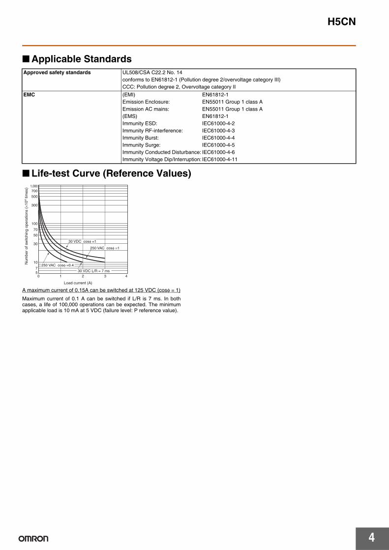
■ Applicable Standards
■ Life-test Curve (Reference Values)
A maximum current of 0.15A can be switched at 125 VDC (cosφ = 1)
Maximum current of 0.1 A can be switched if L/R is 7 ms. In bothcases, a life of 100,000 operations can be expected. The minimumapplicable load is 10 mA at 5 VDC (failure level: P reference value).
Approved safety standards UL508/CSA C22.2 No. 14conforms to EN61812-1 (Pollution degree 2/overvoltage category III)CCC: Pollution degree 2, Overvoltage category II
EMC (EMI) EN61812-1Emission Enclosure: EN55011 Group 1 class AEmission AC mains: EN55011 Group 1 class A(EMS) EN61812-1Immunity ESD: IEC61000-4-2Immunity RF-interference: IEC61000-4-3Immunity Burst: IEC61000-4-4Immunity Surge: IEC61000-4-5Immunity Conducted Disturbance: IEC61000-4-6Immunity Voltage Dip/Interruption: IEC61000-4-11
Load current (A)
1,000700
500
300
100
70
50
30
10
50 1 2 3 4
7
30 VDC cosφ =1
250 VAC cosφ =1
30 VDC L/R = 7 ms
250 VAC cosφ =0.4Num
ber
of s
witc
hing
ope
ratio
ns (
×104
times
)
H5CN
5
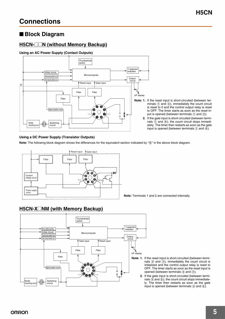
Connections
■ Block Diagram
H5CN-@@N (without Memory Backup)Using an AC Power Supply (Contact Outputs)
Using a DC Power Supply (Transistor Outputs)Note: The following block diagram shows the differences for the equivalent section indicated by “a” in the above block diagram.
H5CN-X@NM (with Memory Backup)
UP display
7-segment indicator
Output circuit
Gate inputReset input
Quartzcrystal oscillator circuit
Power interruption detection circuit
Initial circuitMicrocomputer
Signal insulation circuit
Filter
FilterFilter
Rectifier/smoothing circuit
Switching circuit
4
3
2
1 8
7
6
5
Thumbwheel switch
a
Note: 1. If the reset input is short-circuited (between ter-minals A and C), immediately the count circuitis reset to 0 and the control output relay is resetto OFF. The timer starts as soon as the reset in-put is opened (between terminals A and C).
2. If the gate input is short-circuited (between termi-nals A and D), the count circuit stops immedi-ately. The timer then restarts as soon as the gateinput is opened (between terminals A and D).
Filter FilterFilter
Reset input Gate input
Power supply circuit
Constant voltage circuit
Note: Terminals 1 and 2 are connected internally.
UP display
7-segment indicator
Thumbwheel switch
Output circuit
Reset inputGate input
Quartzcrystal oscillator circuitPower interruption detection circuit
Initial circuit
Non-volatile memory
Microcomputer
Signal insulation circuit
FilterFilter
6 78
9
10111
2
3
45
Filter
Rectifier/smoothing circuit
Switching circuit
Note: 1. If the reset input is short-circuited (between termi-nals C and G), immediately the count circuit isinitialized and the control output relay is reset toOFF. The timer starts as soon as the reset input isopened (between terminals C and G).
2. If the gate input is short-circuited (between termi-nals C and E), the count circuit stops immediate-ly. The timer then restarts as soon as the gateinput is opened (between terminals C and E).
H5CN
6
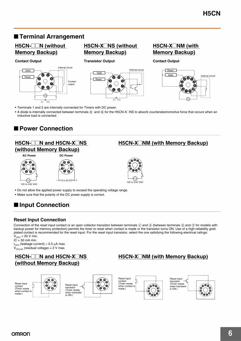
■ Terminal Arrangement
■ Power Connection
■ Input Connection
Reset Input ConnectionConnection of the reset input contact or an open collector transistor between terminals A and C (between terminals C and G for models with backup power for memory protection) permits the timer to reset when contact is made or the transistor turns ON. Use of a high-reliability gold-plated contact is recommended for the reset input. For the reset input transistor, select the one satisfying the following electrical ratings:VCEO = 20 V min.IC = 50 mA min.ICEO (leakage current) = 0.5 μA max.VCE(sat) (residual voltage) = 2 V max.
H5CN-@@N (without Memory Backup)Contact Output
H5CN-X@NS (without Memory Backup)Transistor Output
H5CN-X@NM (with Memory Backup)Contact Output
• Terminals 1 and 2 are internally connected for Timers with DC power.• A diode is internally connected between terminals E and F for the H5CN-X@NS to absorb counterelectromotive force that occurs when an
inductive load is connected.
4
3
2
1 8
7
6
5
(+)(-)
Internal circuitGate
Reset
Contact output
4
3
2
1 8
7
6
5
(+)(-)
Internal circuitGate
Reset 6 78
9
10111
2
3
45
Reset
Gate Internal circuit
H5CN-@@N and H5CN-X@NS (without Memory Backup)
H5CN-X@NM (with Memory Backup)
• Do not allow the applied power supply to exceed the operating voltage range.• Make sure that the polarity of the DC power supply is correct.
100 to 240 VAC
12 to 48 VDC
AC Power DC Power
100 to 240 VAC
H5CN-@@N and H5CN-X@NS (without Memory Backup)
H5CN-X@NM (with Memory Backup)
Gate input contact (Timer stops when contact is made.)
Reset input contact (Timer resets when contact is made.)
Reset input transistor(Timer resets when transistor is ON.)
Reset input contact (Timer resets when contact is made.)
Reset input transistor(Timer resets when transistor is ON.)
H5CN
7
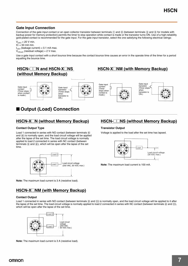
Gate Input ConnectionConnection of the gate input contact or an open collector transistor between terminals A and D (between terminals C and E for models with backup power for memory protection) permits the timer to stop operation while contact is made or the transistor turns ON. Use of a high-reliability gold-plated contact is recommended for the gate input. For the gate input transistor, select the one satisfying the following electrical ratings:
VCEO = 20 V min.IC = 50 mA min.ICEO (leakage current) = 0.1 mA max.VCE(sat) (residual voltage) = 2 V max.
Use a gate input contact with a short bounce time because the contact bounce time causes an error in the operate time of the timer for a period equalling the bounce time.
■ Output (Load) Connection
H5CN-X@N (without Memory Backup)Contact Output TypeLoad 1 connected in series with NO contact (between terminals F and H) is normally open, and the load circuit voltage will be applied after the lapse of the set time. The load circuit voltage is normally applied to load 2 connected in series with NC contact (between terminals E and H), which will be open after the lapse of the set time.
Note: The maximum load current is 3 A (resistive load).
H5CN-@@NS (without Memory Backup)Transistor OutputVoltage is applied to the load after the set time has lapsed.
Note: The maximum load current is 100 mA.
H5CN-X@NM (with Memory Backup)Contact OutputLoad 1 connected in series with NO contact (between terminals I and K) is normally open, and the load circuit voltage will be applied to it after the lapse of the set time. The load circuit voltage is normally applied to load 2 connected in series with NC contact (between terminals H and K), which will be open after the lapse of the set time.
Note: The maximum load current is 3 A (resistive load).
H5CN-@@N and H5CN-X@NS (without Memory Backup)
H5CN-X@NM (with Memory Backup)
Gate input contact (Timer stops when contact is made.)
Gate input transistor (Timer stops when transistor is ON.)
Gate input contact (Timer stops when contact is made.)
Gate input transistor (Timer stops when transistor is ON.)
Load 2
Load 1 Load circuit voltage (250 VAC, 30 VDC max.)
Load
Load circuit voltage(30 VDC max.)
Load 2
Load 1
Load circuit voltage(250 VAC, 30 VDC max.)
H5CN
8
Operation
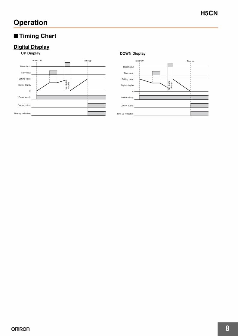
■ Timing Chart
Digital DisplayUP Display DOWN Display
Reset input
Gate input
Time up
Setting value
0
Control output
Power supply
Time up indication
Digital display
Reset input
Gate input
Time up
Setting value
0
Control output
Time up indication
Digital display
Power supply
No
digi
tal
dis
play
No
digi
tal
dis
play
Power ON Power ON

H5CN
9
DimensionsNote: All units are in millimeters unless otherwise indicated.
■ Dimensions without Flush Mounting Adapter
■ Dimensions with Flush Mounting Adapter
■ Dimensions with Front Connecting Socket
Note: These dimensions vary with the kind of DIN track (reference value).
H5CN-X@N/-Y@N/-X@NS (Flush Mounting/Surface Mounting Models)
H5CN-X@NM (Flush Mounting/Surface Mounting Models)
44.8 × 44.8
44.8 × 44.8
▲
▲
8 pins
11 pins
48
48
6
72.514.2
97.6
(10.9)
48
48
6
72.514.2
97.6
(10.9)
Panel
Y92F-30 (order separately)Flush Mounting Adapter
H5CN-X@N/-Y@N/-X@NS (Adapter Ordered Separately)
H5CN-X@NM (Adapter Ordered Separately)
P3GA-11 (order separately)Back Connecting Socket
PanelY92F-30 (order separately)Flush Mounting Adapter
95.1
P3G-08 (order separately)Back Connecting Socket
Panel Cutout
Note: 1. Panel thickness: 1 to 5 mm
3. No cover: N = (48n − 2.5) +1/−0
With hard cover: N = {48n − 2.5 + (n − 1) x 3} +1/−0
N
2. When gang-mounting the Unit, the orientation of the Adapter must be changed depending on whether Units are mounted horizontally or vertically.
45 +0.6−0
45 +0.6−0
45 +0.6−0
The standard panel cutout is as below. (Panel cutout conforms to DIN 43700.)
Gang-mounting of more than 2 units (horizontally)
Radius: 0.5 max.
Radius: 0.5 max.
H5CN-@@N,-X@NS
H5CN-X@NM
P2CF-08(E) P2CF-11(E)
H5CN-@@N,-X@NS
+adapter
H5CN-X@NM
+adapter
Flush Mounting

H5CN
10
■ Accessories (Order Separately)Note: All units are in millimeters unless otherwise indicated.
20.3 max.
7.83 4.5
35.4
4
40±0.2
70 max.
50 max.
20.3 max.
Track Mounting/Front Connecting Socket
P2CF-08Surface Mounting Holes
Two, 4.5 dia. or two, M4
Terminal Arrangement/ Internal Connections (Top View)
Eight, M3.5 x 7.5 sems
Two, 4.5 dia. holes
40±0.2
7.83 4.5
35.4
4
Track Mounting/Front Connecting SocketP2CF-11
Surface Mounting Holes
Two, 4.5 dia. or two, M4
70 max.
50 max.31.2 max.
Terminal Arrangement/ Internal Connections (Top View)
Eleven, M3.5 x 7.5 sems
Two, 4.5 dia. holes
45
45 4.9 17
45
45
25.6
4.516.3
6.2
27 dia.
Back Connecting SocketP3G-08
P3GA-1127 dia.
Terminal Arrangement/ Internal Connections (Bottom View)
Terminal Arrangement/ Internal Connections (Bottom View)
H5CN
11
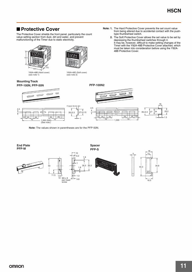
■ Protective CoverThe Protective Cover shields the front panel, particularly the count value setting section from dust, dirt and water, and prevent malfunctioning of the Timer due to static electricity.
Note: 1. The Hard Protective Cover prevents the set count value from being altered due to accidental contact with the push-type thumbwheel switch.
2. The Soft Protective Cover allows the set value to be set by depressing the thumbwheel switches through it. It may be, however, difficult to make setting changes of the Timer with the Y92A-48B Protective Cover attached, which must be taken into consideration before using the Y92A-48B Protective Cover.
Y92A-48B (Hard cover)(see note 1)
Y92A-48D (Soft cover)(see note 2)
4.5
15 25 25 25 25 *10 10
7.3±0.15
35±0.3 27±0.15
1
4.5
15 25 25 25 25 1510 101,000
27 24
16
29.2
1 1.5
50
11.5
106.2
1.8
135.5 35.3
1.8
1.3
4.8
516
12
44.3
16.510
34.8
35±0.3
Mounting Track PFP-100N, PFP-50N PFP-100N2
End PlatePFP-M
SpacerPFP-S
1,000 (500)(See note.)
Note: The values shown in parentheses are for the PFP-50N.
M4 x 8 pan head screw

H5CN
12
Safety Precautions● Be sure to read the precautions for all Timers in the website at: http://www.ia.omron.com/.Warning Indications
Meaning of Product Safety Symbols
• Make sure the proper product is specified for the application.• For correct use, do not subject the product to the following
conditions.• Dramatic temperature fluctuations
• High humidity or where condensation may occur
• Severe vibration and shock
• Where excessive dust, corrosive gas, or direct sunlight may be present
• This product is not waterproof or oil resistance. Do not use the product in any of the places subject to splashing liquid or oil atmosphere.
• Use and store the product within the rated ranges given for the product model you are using. If necessary, use forced cooling. If the product is stored below −10°C, allow it to warm up for three hours at room temperature before turning ON the power supply.
• Do not cover the vent holes on the products and the area around the product in order to ensure thermal dissipation.
• Wiring all terminals correctly.• Do not wire the terminals which are not used.• Use specified size crimped terminals (M3.5, thickness 7.2 mm
max.) for wiring with a gage of AWG 24 to AWG 18 (equal to a cross section area of 0.205 to 0.823 mm2).(The wiring stripping length is 5 to 6 mm.)Up to two wires of same size and type, or two crimped terminals can be inserted into a single terminal.
• Use this product within the rated power supply voltage and control output.
• Use a switch, relay, or other contact to turn the power supply ON instantaneously. If the voltage is applied gradually, the power may not be reset or output malfunctions may occur.
• Do not apply the supply voltage directly from external to transistor output.
• Interlock the power to the product with a relay so that the product will not be left in an output on condition for long periods. Leaving the product in an output-on condition for a month or longer, especially in places with high temperatures, may result in deterioration to internal parts, such as an electrolytic capacitor.
• Internal circuit voltage (5 V) is output to the no-voltage input terminals, which may cause some connected devices to malfunction or fail. Check the specifications of the input device (e.g., rated output voltage or whether a power supply circuit diode is built in).To prevent power supply devices from being subjected to charging accidents, connect a diode as in the figure when using a power supply voltage of 5 V or less to operate input devices that do not have a diode built into the power supply circuit.
• Check that the LED indicators are operating normally. Depending on the operating environment, the indicators and plastic parts may deteriorate faster than expected, causing the indicators to fail. Periodically perform inspections and replacements.
• Use tools when separating parts for disposal.• When disposing of the product, observer all local ordinances as
they apply.
• Inrush current will be carried when turning on the power. If the capacity of the power for the product is insufficient, the product cannot start. Use a power supply, breakers, contacts which sufficient capacity. 100 to 240 VAC specifications Approx. 0.8 A for 264 VAC12 to 48 VDC specifications Approx. 0.4 A for 52.8 VDC
• Since 50 ms after the power is turned ON is required as the raise time of the internal circuit voltage, note that the product may not operate in response to any input signal during this period.
CAUTIONIndicates a potentially hazardous situation which, if not avoided, may result in minor or moderate injury or in property damage.
Precautions for Safe Use
Supplementary comments on what to do or avoid doing, to use the product safely.
Precautions for Correct Use
Supplementary comments on what to do or avoid doing, to prevent failure to operate, malfunction or undesirable effect on product performance.
Used to warn of the risk of electric shock under specific conditions.
Used for general prohibitions for which there is no specific symbol.
Used for general mandatory action precautions for which there is no specified symbol.
CAUTIONDo not touch the terminals while power is being supplied. Doing so many occasionally result in minor injury due to electric shock.
Do not use the product where subject to flammable or explosive gas.Otherwise, minor injury from explosion may occasionally occur.
Never disassemble, modify or repair the product or touch any of the internal parts. Minor electric shock, fire, or malfunction may occasionally occur.
The life expectancy of output relays varies considerably with the output load and switching conditions. Always consider the application conditions and use the output relays within their rated load and electrical life expectancy. If the output relays are used past their life expectancy, contact fusing or burning may occasionally occur. Also, never exceed the rated load current. When using a heater, surely use a thermo switch in the load circuit.
Tighten the terminal screws to between 0.74 and 0.90 N·m.Loose screws may occasionally result in fire.
Do not allow pieces of metal, wire clippings, or fine metallic shavings or filings from installation to enter the product. Doing so may occasionally result in electric shock, fire, or malfunction.
Precautions for Safe Use
Precautions for Correct Use
Sensor
Input0V
H5CN
13
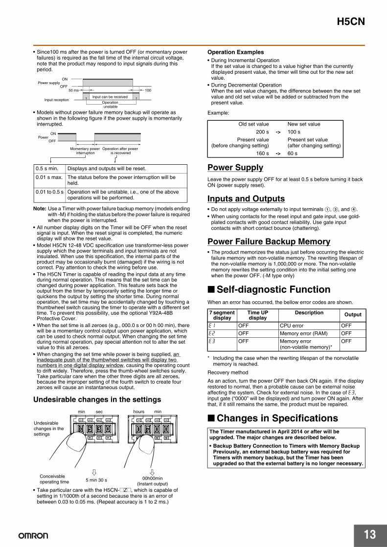
• Since100 ms after the power is turned OFF (or momentary power failures) is required as the fall time of the internal circuit voltage, note that the product may respond to input signals during this period.
• Models without power failure memory backup will operate as shown in the following figure if the power supply is momentarily interrupted.
Note: Use a Timer with power failure backup memory (models ending with -M) if holding the status before the power failure is required when the power is interrupted.
• All number display digits on the Timer will be OFF when the reset signal is input. When the reset signal is completed, the numeric display will show the reset value.
• Model H5CN 12-48 VDC specification use transformer-less power supply which the power terminals and input terminals are not insulated. When use this specification, the internal parts of the product may be occasionally burnt (damaged) if the wiring is not correct. Pay attention to check the wiring before use.
• The H5CN Timer is capable of reading the input data at any time during normal operation. This means that the set time can be changed during power application. This feature sets back the output from the timer by temporarily setting the longer time or quickens the output by setting the shorter time. During normal operation, the set time may be accidentally changed by touching a thumbwheel switch causing the timer to operate with a different set time. To prevent this possibility, use the optional Y92A-48B Protective Cover.
• When the set time is all zeroes (e.g., 000.0 s or 00 h 00 min), there will be a momentary control output upon power application, which can be used to check normal output. When changing the set time during normal operation, pay special attention not to alter the set value to this all zeroes.
• When changing the set time while power is being supplied, an inadequate push of the thumbwheel switches will display two numbers in one digital display window, causing the operating count to drift widely. Therefore, press the thumb-wheel switches surely. Take particular care when the other three digits are all zeroes, because the improper setting of the fourth switch to create four zeroes will cause an instantaneous output.
Undesirable changes in the settings
• Take particular care with the H5CN-@Z@, which is capable of setting in 1/1000th of a second because there is an error of between 0.03 to 0.05 ms. (Repeat accuracy is 1 to 2 ms.)
Operation Examples• During Incremental Operation
If the set value is changed to a value higher than the currently displayed present value, the timer will time out for the new set value.
• During Decremental OperationWhen the set value changes, the difference between the new set value and old set value will be added or subtracted from the present value.
Example:
Power SupplyLeave the power supply OFF for at least 0.5 s before turning it back ON (power supply reset).
Inputs and Outputs• Do not apply voltage externally to input terminals A, C, and D.• When using contacts for the reset input and gate input, use gold-
plated contacts with good contact reliability. Use gate input contacts with short contact bounce (chattering).
Power Failure Backup Memory• The product memorizes the status just before occurring the electric
failure memory with non-volatile memory. The rewriting lifespan of the non-volatile memory is 1,000,000 or more. The non-volatile memory rewrites the setting condition into the initial setting one when the power OFF. (-M type only)
■ Self-diagnostic FunctionWhen an error has occurred, the bellow error codes are shown.
* Including the case when the rewriting lifespan of the nonvolatile memory is reached.
Recovery method
As an action, turn the power OFF then back ON again. If the display restored to normal, then a probable cause can be external noise affecting the system. Check for external noise. In the case of e3, input gate (“0000” will be displayed) and turn power ON again. After that, if it still remains the same, the product must be repaired.
■ Changes in Specifications
ON
OFF50 ms 100
Power supply
Input can be receivedInput reception
Operation unstable
Momentary power interruption
ON
OFFPower
Operation after power is recovered
0.5 s min. Displays and outputs will be reset.
0.01 s max. The status before the power interruption will be held.
0.01 to 0.5 s Operation will be unstable, i.e., one of the above operations will be performed.
min sec
5 min 30 s
hours min
00h00min(Instant output)
Conceivable operating time
Undesirable changes in the settings
Old set value New set value200 s -> 100 s
Present value(before changing setting)
Present set value (after changing setting)
160 s -> 60 s
7 segment display
Time UP display
Description Output
e1 OFF CPU error OFFe2 OFF Memory error (RAM) OFFe3 OFF Memory error
(non-volatile memory)*OFF
The Timer manufactured in April 2014 or after will be upgraded. The major changes are described below.• Backup Battery Connection to Timers with Memory Backup
Previously, an external backup battery was required for Timers with memory backup, but the Timer has been upgraded so that the external battery is no longer necessary.
H5CN
14
• When conforming to EMC standards, refer to the information provided in datasheet for cable selection and other conditions.
• This is a class A product. In residential areas it may cause radio interference, in which case the user may be required to take adequate measures to reduce interference.
• 100-240 VAC types: There is basic insulation between the power supply terminals and input terminals, and between power supply terminals and output terminals, and between input and output terminals.12-48 VDC types: No insulation is provided between the power supply and input terminals. There is basic insulation between power supply terminals and output terminals, and between input and output terminals.
• If double or reinforced insulation is required, use the double or reinforced insulation defined in IEC 60664 that is suitable for the maximum applied voltage for the clearance, solid insulation, and other factors.
Conformance to EN/IEC Standards
In the interest of product improvement, specifications are subject to change without notice.
ALL DIMENSIONS SHOWN ARE IN MILLIMETERS.
To convert millimeters into inches, multiply by 0.03937. To convert grams into ounces, multiply by 0.03527.
Terms and Conditions Agreement Read and understand this catalog. Please read and understand this catalog before purchasing the products. Please consult your OMRON representative if you have any questions or comments. Warranties. (a) Exclusive Warranty. Omron’s exclusive warranty is that the Products will be free from defects in materials and workmanship for a period of twelve months from the date of sale by Omron (or such other period expressed in writing by Omron). Omron disclaims all other warranties, express or implied. (b) Limitations. OMRON MAKES NO WARRANTY OR REPRESENTATION, EXPRESS OR IMPLIED, ABOUT NON-INFRINGEMENT, MERCHANTABILITY OR FITNESS FOR A PARTICULAR PURPOSE OF THE PRODUCTS. BUYER ACKNOWLEDGES THAT IT ALONE HAS DETERMINED THAT THE PRODUCTS WILL SUITABLY MEET THE REQUIREMENTS OF THEIR INTENDED USE. Omron further disclaims all warranties and responsibility of any type for claims or expenses based on infringement by the Products or otherwise of any intellectual property right. (c) Buyer Remedy. Omron’s sole obligation hereunder shall be, at Omron’s election, to (i) replace (in the form originally shipped with Buyer responsible for labor charges for removal or replacement thereof) the non-complying Product, (ii) repair the non-complying Product, or (iii) repay or credit Buyer an amount equal to the purchase price of the non-complying Product; provided that in no event shall Omron be responsible for warranty, repair, indemnity or any other claims or expenses regarding the Products unless Omron’s analysis confirms that the Products were properly handled, stored, installed and maintained and not subject to contamination, abuse, misuse or inappropriate modification. Return of any Products by Buyer must be approved in writing by Omron before shipment. Omron Companies shall not be liable for the suitability or unsuitability or the results from the use of Products in combination with any electrical or electronic components, circuits, system assemblies or any other materials or substances or environments. Any advice, recommendations or information given orally or in writing, are not to be construed as an amendment or addition to the above warranty. See http://www.omron.com/global/ or contact your Omron representative for published information. Limitation on Liability; Etc. OMRON COMPANIES SHALL NOT BE LIABLE FOR SPECIAL, INDIRECT, INCIDENTAL, OR CONSEQUENTIAL DAMAGES, LOSS OF PROFITS OR PRODUCTION OR COMMERCIAL LOSS IN ANY WAY CONNECTED WITH THE PRODUCTS, WHETHER SUCH CLAIM IS BASED IN CONTRACT, WARRANTY, NEGLIGENCE OR STRICT LIABILITY. Further, in no event shall liability of Omron Companies exceed the individual price of the Product on which liability is asserted. Suitability of Use. Omron Companies shall not be responsible for conformity with any standards, codes or regulations which apply to the combination of the Product in the Buyer’s application or use of the Product. At Buyer’s request, Omron will provide applicable third party certification documents identifying ratings and limitations of use which apply to the Product. This information by itself is not sufficient for a complete determination of the suitability of the Product in combination with the end product, machine, system, or other application or use. Buyer shall be solely responsible for determining appropriateness of the particular Product with respect to Buyer’s application, product or system. Buyer shall take application responsibility in all cases. NEVER USE THE PRODUCT FOR AN APPLICATION INVOLVING SERIOUS RISK TO LIFE OR PROPERTY OR IN LARGE QUANTITIES WITHOUT ENSURING THAT THE SYSTEM AS A WHOLE HAS BEEN DESIGNED TO ADDRESS THE RISKS, AND THAT THE OMRON PRODUCT(S) IS PROPERLY RATED AND INSTALLED FOR THE INTENDED USE WITHIN THE OVERALL EQUIPMENT OR SYSTEM. Programmable Products. Omron Companies shall not be responsible for the user’s programming of a programmable Product, or any consequence thereof. Performance Data. Data presented in Omron Company websites, catalogs and other materials is provided as a guide for the user in determining suitability and does not constitute a warranty. It may represent the result of Omron’s test conditions, and the user must correlate it to actual application requirements. Actual performance is subject to the Omron’s Warranty and Limitations of Liability. Change in Specifications. Product specifications and accessories may be changed at any time based on improvements and other reasons. It is our practice to change part numbers when published ratings or features are changed, or when significant construction changes are made. However, some specifications of the Product may be changed without any notice. When in doubt, special part numbers may be assigned to fix or establish key specifications for your application. Please consult with your Omron’s representative at any time to confirm actual specifications of purchased Product. Errors and Omissions. Information presented by Omron Companies has been checked and is believed to be accurate; however, no responsibility is assumed for clerical, typographical or proofreading errors or omissions.
2017.4
In the interest of product improvement, specifications are subject to change without notice.
OMRON Corporation Industrial Automation Company http://www.ia.omron.com/
(c)Copyright OMRON Corporation 2017 All Right Reserved.