solid-state timer h3ca · 2017-08-23 · solid-state timer h3ca din-sized (48 x 48, 45 x 75 mm)...
TRANSCRIPT

http://www.ia.omron.com/ 1(c)Copyright OMRON Corporation 2007 All Rights Reserved.
Solid-state Timer
H3CADIN-sized (48 x 48, 45 x 75 mm) Timer with Digital Setting and LCD Display
• Dual power supplies for free AC/DC.
• Eight operation modes selectable with one unit.
• Any desired time can be set digitally within a range from 0.1 seconds to 9,990 hrs.
• Four external signal inputs.
• ON/OFF indicator for control output and bar indicator for remaining time.
• Conforms to UL, CSA, and CE marking.
Ordering Information
Note: 1. Specify both the model number and supply voltage when ordering for the H3CA-8H and H3CA-8.2. The operation/resetting system depends on the selected operation mode. For details, see “Timing Chart”.3. The 8 operation modes are as follows:
A: ON-delay operationB: Repeat cycle operationC: Signal ON/OFF-delay operation (1)D: Signal OFF-delay operation (1)
E: Interval operationF: One-shot and flicker operationG: Signal ON/OFF-delay operation (2)H: Signal OFF-delay operation (2)
■ Accessories (Order Separately)
Note: Track mounted socket can be used as a front connecting socket.
Specifications
■ Time RangesA desired time can be set within a range of 0.1 s to 9,990 hrs by combining the three thumbwheel switch modules for time setting and one module for time unit selection.
Operation/resetting system
Operation mode Terminal Time-limit contact
Instantaneous contact
Mounting
Surface mounting/
track mounting
Flush mounting
Time-limit operation/self-resetting/external resetting (see note 2)
8 operation modes (selectable) (see note 3)
11-pin round socket SPDT --- H3CA-A H3CA-A
Front screw H3CA-FA ---
Time-limit operation/self-resetting
ON-delay operation 8-pin round socket DPDT --- H3CA-8 H3CA-8
SPDT SPDT H3CA-8H H3CA-8H
Timer Track mounted socket (See note.)
Back connecting socket
Solder terminal Screw terminal
H3CA-A P2CF-11 PL11 P3GA-11
H3CA-8H/H3CA-8 P2CF-08 PL08 P3G-08
Time unit 0.1 s 1 s 0.1 min 1 min 0.1 hrs 1 hr 10 hrs
Time range 1 to 999 (3 digits)

http://www.ia.omron.com/ 2(c)Copyright OMRON Corporation 2007 All Rights Reserved.
H3CA■ Ratings
Note: 1. Single-phase, full-wave rectified power sources may be used for 24 to 240 VDC.2. Refer to Safety Precautions for All Times when combining the Timer with an AC 2-wire proximity sensor.
■ Characteristics
Item H3CA-A/H3CA-FA H3CA-8 H3CA-8H
Rated supply voltage (See note 2.)
24 to 240 VAC (50/60 Hz),12 to 240 VDC (permissible ripple: 20% max.)
100/110/120, 200/220/240 VAC, (50/60 Hz),24 VDC, 110 VDC (permissible ripple: 20% max.) (See note 1.)
Operating voltage range 90% to 110% of rated supply voltage 85% to 110% of rated supply voltage
Power consumption AC: approx. 4 VADC: approx. 2 W
AC: approx. 10 VA/1 WDC: approx. 1 W
AC: approx. 10 VA/1.5 WDC: approx. 2 W
Control outputs 3 A at 250 VAC, resistive load (cosφ = 1)
Accuracy of operating time
±0.3% ±0.05 s
Influence of voltage
Influence of temperature
Setting error ±0.5% ±0.05 s max.
Reset time H3CA-A/-FA: 0.5 s max.H3CA-8H/-8: 0.1 s max.
Insulation resistance 100 MΩ min. (at 500 VDC)
Dielectric strength 2,000 VAC, 50/60 Hz for 1 min (between current-carrying and non-current-carrying parts and between contact and control circuit)1,000 VAC, 50/60 Hz for 1 min (between non-continuous contacts)
Impulse withstand voltage
3 kV
Vibration resistance Destruction: 10 to 55 Hz with 0.75-mm double amplitude for 1 h each in three directionsMalfunction: 10 to 55 Hz with 0.5-mm double amplitude for 10 min each in three directions
Shock resistance Destruction: 980 m/s2
Malfunction: 98 m/s2
Ambient temperature Operating: –10°C to 55°CAmbient humidity Operating: 35% to 85%
Life expectancy Mechanical: 10,000,000 operations min. (under no load at 1,800 operations/h)Electrical: 100,000 operations min. (3 A at 250 VAC, cosφ = 1 at 1,800 operations/h)
See Lift-test Curve for more details.
Approved standards UL508, CSA C22.2 No. 14, LR, NKConforms to EN61010-1.
EMC (EMI) EN61326Emission Enclosure: EN55011 Group 1 class AEmission AC mains: EN55011 Group 1 class A(EMS) EN61326Immunity ESD: EN61000-4-2: 4 kV contact discharge (level 2)
8 kV air discharge (level 3)Immunity RF-interference: EN61000-4-3: 10 V/m (Amplitude-modulated, 80 MHz to 1 GHz) (level 3);
10 V/m (Pulse-modulated, 900 MHz ±5 MHz) (level 3)Immunity ConductedDisturbance: EN61000-4-6: 10 V (0.15 to 80 MHz) (according to EN61000-6-2)Immunity Burst: EN61000-4-4: 2 kV power-line (level 3);
1 kV I/O signal-line (level 4)Immunity Surge: EN61000-4-5: 1 kV line to lines (power and output lines) (level 3);
2 kV line to ground (power and output lines) (level 3)Immunity Voltage Dip/Interruption EN61000-4-11: 0.5 cycle, 100% (rated voltage)
Weight H3CA-A: approx. 110 gH3CA-FA: approx. 190 g
http://www.ia.omron.com/ 3(c)Copyright OMRON Corporation 2007 All Rights Reserved.
H3CA
Engineering Data
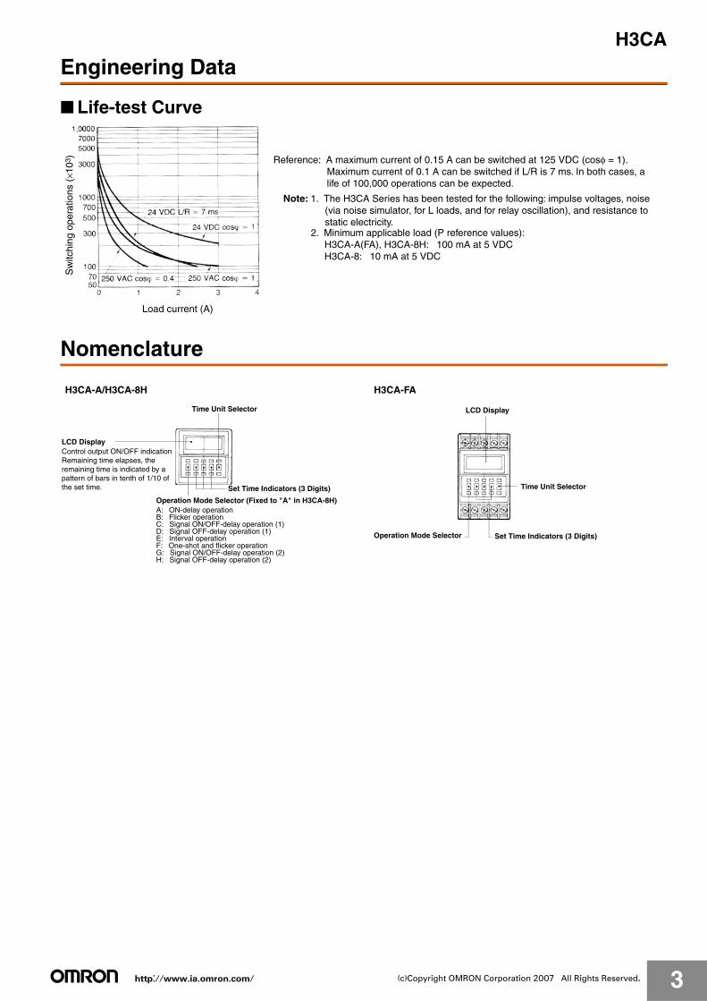
■ Life-test Curve
Nomenclature
Sw
itchi
ng o
pera
tions
(×1
03)
Load current (A)
Reference: A maximum current of 0.15 A can be switched at 125 VDC (cosφ = 1). Maximum current of 0.1 A can be switched if L/R is 7 ms. In both cases, a life of 100,000 operations can be expected.
Note: 1. The H3CA Series has been tested for the following: impulse voltages, noise (via noise simulator, for L loads, and for relay oscillation), and resistance to static electricity.
2. Minimum applicable load (P reference values): H3CA-A(FA), H3CA-8H: 100 mA at 5 VDC H3CA-8: 10 mA at 5 VDC
H3CA-A/H3CA-8H H3CA-FA
Time Unit Selector
Set Time Indicators (3 Digits)
LCD Display
Operation Mode Selector (Fixed to "A" in H3CA-8H)A: ON-delay operationB: Flicker operationC: Signal ON/OFF-delay operation (1)D: Signal OFF-delay operation (1)E: Interval operationF: One-shot and flicker operationG: Signal ON/OFF-delay operation (2)H: Signal OFF-delay operation (2)
LCD Display
Time Unit Selector
Operation Mode Selector Set Time Indicators (3 Digits)
Control output ON/OFF indication Remaining time elapses, the remaining time is indicated by a pattern of bars in tenth of 1/10 of the set time.

http://www.ia.omron.com/ 4(c)Copyright OMRON Corporation 2007 All Rights Reserved.
H3CA
Operation
■ Timing Chart
H3CA-A (FA)
ON-delay Operation (A Mode)Signal Start
t: Set time; t-a: Time within the set time
t: Set time; R: Resetting time; t-a: Time within the set time
Power-ON Start/Power-OFF Reset
Note: The minimum signal input time is 0.05 s.
Flicker Operation (B Mode)Signal Start Power-ON Start/Power-OFF Reset
t: Set time; t-a: Time within the set time
t: Set time
Note: The minimum signal input time is 0.05 s.

http://www.ia.omron.com/ 5(c)Copyright OMRON Corporation 2007 All Rights Reserved.
H3CA
t: Set time; t-a: Time within the set time t: Set time; t-a: Time within the set time
Signal ON/OFF-delay Operation 1 (C Mode) Signal OFF-delay Operation 1 (D Mode)
Note: 1. The minimum signal input time is 0.05 s. 2. Operation 1 refers to the version in which the output relay operates when the Start signal is ON.
Interval Operation (E Mode)Signal Start
t: Set time; t-a: Time within the set time
t: Set time
Note: The minimum signal input time is 0.05 s.
One-shot and Flicker Operation (F Mode)Signal Start Power-ON Start/Power-OFF Reset
Note: The minimum signal input time is 0.05 s.t: Set time; t-a: Time within the set time t: Set time; t-a: Time within the set time
Note: The minimum signal input time is 0.05 s.
Signal ON/OFF-delay Operation 2 (G Mode) Signal ON/OFF-delay Operation 2 (H Mode)
Note: 1. The minimum signal input time is 0.05 s. 2. Operation 2 refers to the version in which the output relay does not operate when the Start signal is ON.
t: Set time; t-a: Time within the set time
t-a
t: Set time; t-a: Time within the set time

http://www.ia.omron.com/ 6(c)Copyright OMRON Corporation 2007 All Rights Reserved.
H3CA
ON-delay Operation
Repeat Cycle Operation
2. The set time is the sum of t1 and t2.
t: Set time; t-a: Time within the set time
t: Set time; t-a: Time within the set time
If a check signal is input to the timer during the lapse of a set time, the remaining set time will become 0 and the timer will enter the next control state. Also, while a check signal is being input, the elapsed time measurement of the set time is not performed.
Note: 1. This timing chart indicates the gate input in operation mode A (ON-delay operation).
How to Use Gate Signal Input How to Use Check Signal Input
H3CA-8H

http://www.ia.omron.com/ 7(c)Copyright OMRON Corporation 2007 All Rights Reserved.
H3CA
DimensionsNote: All units are in millimeters unless otherwise indicated.
■ Timers
■ Accessories (Order Separately)
Track Mounted Front Connecting Socket
Panel Cutouts
H3CA-A/-8H H3CA-FA
Horizontally connecting n unitsNo front cover:N = (48n − 2.5)+1/−0With front cover:N = {48n − 2.5 + (n − 1) x 3}+1/−0
Mounting HolesTwo,M4 or 4.5 dia. holes
(N)
When mounting a single unit t = 1 to 3.2 mm
Note: When mounting two or more timers in line, dimension L between two adjacent timers should be 10 mm min.
45+0.6 (N)−0
Mounting Holes
P2CF-11
Terminal Arrangement(Top View)
108.1
P2CF-08
97.2
Mounting HolesTerminal Arrangement(Top View)
Eleven, M3.5 × 7.5 sems
Eight, M3.5 × 7.5 sems
Two, 4.5 dia. holes
Two, 4.5 dia. holes
Note: P2CF-08 can be used as a front connecting socket.
Mounting Height of Timer with Socket
Mounting Height of Timer with Socket
Two, 4.5 dia. or Two, M4
Two, 4.5 dia. mounting holes
Note: P2CF-11 can be used as a front connecting socket.

http://www.ia.omron.com/ 8(c)Copyright OMRON Corporation 2007 All Rights Reserved.
H3CABack Connecting Socket
79.6
P3GA-11
Terminal Arrangement(Bottom View)
Terminal Arrangement(Bottom View)
P3G-08
86.310.9
P3G-08
Mounting HolesTerminal Arrangement(Bottom View)
PL11
Approx. 20.5
Two, 2 dia. holes
35 max.
M3.5
Mounting HolesTerminal Arrangement(Bottom View)
PL08
27 dia.
79.6
Mounting Height of Timer with Socket
Mounting Height of Timer with Socket
Mounting Height of Timer with Socket
Two, 3.5 dia. or 3M socket mounting holes
Two, 3.5 dia. or 3M socket mounting holes Hold-down
clipY92H-1
Two, 2 dia. holes

http://www.ia.omron.com/ 9(c)Copyright OMRON Corporation 2007 All Rights Reserved.
H3CAMounting Track (Meets DIN EN50022)
Protective Cover
(see note)
PFP-100N/PFP-50N PFP-100N2Twelve, 25 × 4.5 elliptic holes (see note)
Note: This dimension applied to PFP-50N.
PFP-M PFP-S
Y92F-30
Note: Pay attention to the orientation of the adapter when mounting two or more timers in a vertical or horizontal line.
Note: A total of 12-25 × 4.5 elliptic holes are provided with 6 holes cut from each rail end at a pitch of 10 mm between holes.
End Plate
Adapter for Flush Mounting
Y92A-48B/Y92A-48D
Y92A-48BHard Plastic Cover
Y92A-48DSoft PVC Cover
The protective cover protects the front panel, particularly the time setting section, against dust, dirt and water drip, as well as prevents the set value from being altered due to accidental contact with the time setting knob.
Note: The Y92A-48B Protective Cover is made of a hard plastic and therefore, must be removed to change the timer set value. However, since the Y92A-48D Protective Cover is made of PVC, the set value can be altered by pressing on the surface of the cover.
It may be, however, difficult to make setting changes of the Timer with the Y92A-48B Protective Cover attached, which must be taken into consideration before using the Y92A-48B Protective Cover.
When attaching the Y92A-48A to the Timer to be panel-mounted, use the Y92F-30 Mounting Adapter along with the Timer.
The Protective Cover cannot be, however, used for the H3CA-FA Series.

http://www.ia.omron.com/ 10(c)Copyright OMRON Corporation 2007 All Rights Reserved.
H3CA
Installation
■ Terminal Arrangement
■ Input Connections
Signal InputsConnect the start input contact between terminals C and F, the reset input contact between terminals C and G, the gate input contact between terminals C and E, and the check input contact between terminals C and D.
For each signal input contact, use a gold-plated contacts with high reliability. Be sure that these input signals satisfy the following requirements: a resistance of 1 kΩ (max.) and a residual voltage of 1 V (max.) when the contact is made.
Solid-state Signal InputsConnect the start input transistor between terminals C and F, the reset input transistor between terminals C and G, the gate input transistor between terminals C and E, and the check input transistor between terminals C and D.
For signal input, use an open collector type transistor with characteristics: VCEO = 20 V min., VCE(S) = 1 V max., IC = 50 mA min. and ICBO = 0.5 μA max. In addition, be sure that the input signals satisfy the following requirements: a resistance of 1 kΩ (max.) and a residual voltage of 1 V (max.) when the transistor is ON, and a resistance of 200 kΩ (min.) when the transistor is OFF.
H3CA-A H3CA-FA
(Seenote2)
(Seenote2)
* * * ** * * *
Note: 1. *C: Check: 3-4*G: Gate: 3-5*S: Start: 3-6*R: Reset: 3-7
Note: 1. *C: Check: X-E1*G: Gate: X-D1*S: Start: X-C1*R: Reset: X-B1
(+) or(-)
(+) or(-)
(+) or (-)
(+)
or (
-)
2. Conventional time-limit contacts are symbolized as . However, the contacts of H3CA-A are symbolized as because timer has 8 operation modes. 2. Conventional time-limit contacts are symbolized as .
However, the contacts of H3CA-FA are symbolized as because timer has 8 operation modes.

http://www.ia.omron.com/ 11(c)Copyright OMRON Corporation 2007 All Rights Reserved.
H3CAFrom a solid-state circuit (proximity sensor, photoelectric sensor, or the like) with rated power supply voltage ranging from 6 to 30 VDC, input signals can also be applied by other than an open collector type transistor as shown in the following diagram. The input signal from a solid-state circuit is applied when output transistor Tr turns ON. In terms of signal voltage, the signal is input when it goes from a high to low level. Again, the residual voltage should be 1 V (max.) when the transistor is ON. As the current output from the timer to Tr is approximately 0.1 mA, this connection is possible provided the residual voltage is kept to a maximum of 1 V.
Note: Except for the power supply circuitry, avoid the laying of input signal wires in parallel or in the same conduit with high-tension or power lines. It is recommended to use shielded wires or wiring with independent metal conduits for the shortest possible distance.
Solid-state circuit (proximity sensor, photoelectric sensor, etc.)
H3CA-8
(+)(-) (+)(-)
H3CA-8H

http://www.ia.omron.com/ 12(c)Copyright OMRON Corporation 2007 All Rights Reserved.
H3CA■ Application ExamplesStandard type H3CA is used for the following application examples. In the schematic diagrams, each thick the indicates the wiring necessary for selecting the desired operation mode.
ON-delay Operation (A Mode)Power-ON Start/Power-OFF Reset Signal Start/Signal Reset
(+) or (−)(+)
(+)
Flicker Operation (B Mode)Power-ON Start/Power-OFF Reset Signal Start/Signal Reset
(+)
(+)
Signal ON/OFF-delay Operation 1 (C Mode)
t: Set time, t-a: Time within the set time
t-a
Signal OFF-delay Operation 1 (D Mode)Signal Start/Instantaneous Operation/Time-limit Reset
(+) (+)
or (−)
(+) or (−)or (−)
(+) or (−)
(+) or (−)
(+) or (−)
or (−)
or (−)
or (−) or (−)
(+) or (−)
Signal ON/OFF-start/Instantaneous Operation/Time-limit Reset

http://www.ia.omron.com/ 13(c)Copyright OMRON Corporation 2007 All Rights Reserved.
H3CASignal ON/OFF-delay Operation 2 (G Mode)
Signal Start/Signal Reset
Interval Operation (E Mode)Power-ON Start/Power-OFF Reset Signal Start/Signal Reset
One-shot and Flicker Operation (F Mode)Power-ON Start/Power-OFF Reset
Signal OFF-delay Operation 2 (H Mode)Signal/Instantaneous Operation/Time-limit Reset
(+)
(+)
(+) or (−)(+) or (−)
(+) or (−)
(+) or (−)
(+) or (−)(+) or (−)
(+) or (−)
(+)or (−)
(+)or (−)
or (−)
(+)or (−)
or (−)
Signal ON/OFF-start/Instantaneous Operation/Time-limit Reset

http://www.ia.omron.com/ 14(c)Copyright OMRON Corporation 2007 All Rights Reserved.
H3CA
Safety Precautions
How to Change Operation ModeOperate the pushbuttons of the thumbwheel switch, located at the leftmost position on the front panel to set the operation mode. Eight operation modes (A, B, C, D, E, F, G, and H) are selectable and the selected operation mode is displayed in the operation mode display window.
How to Change Time Unit and Rated TimeOperate the pushbuttons of the rightmost thumbwheel switch to select the desired time unit. Seven time units (0.1 s, s, 0.1 m, m, 0.1 h, h, or 10 h) are selectable and the selected time unit is displayed in the time unit display window. The desired rated time is specified by operating the three thumbwheel switches in the middle of the front panel. The range of rated time is 001 to 999 for each unit.
Time Unit and Rated Time
!CAUTION
1. Do not change the time unit, rated time, or operation mode while the timer is in operation. Otherwise, the timer may malfunction or be damaged. Be sure to turn off the power supply to the timer before changing the timer unit, rated time or operation mode.
2. Note that output will be generated in C, D, E, G, or H mode even if the rated time is set to 000. No output will be generated in A, B, or F mode.
Connecting the Operating Power SupplyThe H3CA-8@ contains a capacitor-drop power circuit. Use a sinusoidal power supply with a commercial frequency. Do not use power supplies with a high frequency component (such as inverter power supplies) for Timers with 100 to 240-VAC specifications. Using these power supplies can damage internal circuits.
The power supply connections to the H3CA-A and H3CA-FA can be made without regard to polarity for both AC and DC power supplies; just connect to the specified terminals (2 and 10, or A1 and A2). When connecting a DC power supply to the H3CA-8 or H3CA-8H, however, the polarity must be connected as indicated.
Although there is a wide range of power connectable to the H3CA-A and H3CA-FA, be sure that there is no inductive voltage or residual voltage applied to the timer power supply terminals (2 and 10, or A1 and A2) when the power switch is turned OFF. (Inductive voltage can be generated in the power supply line if it is placed in parallel with high-voltage or power lines.)
A DC power supply can be connected if its ripple factor is 20% or less and the mean voltage is within the rated operating voltage range of the Timer.
Connect the power supply voltage through a relay or switch in such a way that the voltage reaches a fixed value at once or the Timer may not be reset or a timer error could result.
H3CA-8 and H3CA-8H Timers with AC specifications are equivalent to capacitor loads. When switching the Timer power supply with an SSR, use an SSR with a withstand voltage of twice the power supply voltage.
Since the H3CA-8 and H3CA-8H Timers of AC specifications externally discharges a part of internal energy when the power is turned OFF, it may malfunction if an extremely sensitive relay is used with the following sequence circuit.If such a malfunction occurs, change the circuit configuration as shown below on the right side.
Time unit Rated time
0.1 s 0.1 to 99.9 s
s 1 to 999 s
0.1 m 0.1 to 99.9 m
m 1 to 999 m
0.1 h 0.1 to 99.9 h
h 1 to 999 h
10 h 10 to 9,990 h
Note: The operation mode is fixed to "A" for H3CA-8H.
Remaining time displayThe remaining time is displayed as a decreasing percentage between 0% and 100%.
Time unit selector
Time unit display window0.1 s, s, 0.1 m0.1 h, h, 10 h
Rated time selector
Rated time display window001 to 999
T/b
X/a
T/b
X/a
X/aIf malfunction is expected.

http://www.ia.omron.com/ 15(c)Copyright OMRON Corporation 2007 All Rights Reserved.
H3CAInput/OutputThe operation of the output contacts varies with the operation specifications. Before making connections, check the operation specifications and operating conditions using the application examples provided.
The H3CA-A and H3CA-FA do not use transformers. Simultaneous inputting power from two or more power supplies to separate timers or counters from a single input contact or transistor is not possible.
For the power supply of an input device, use an isolating transformer, of which the primary and secondary windings are mutually isolated and the secondary winding is not grounded.
A transformer is not used in the power supplies for the H3CA-A and H3CA-FA. You can therefore receive an electrical shock by touching the input terminals when the power supply voltage is being applied. Take adequate precautions to protect against electrical shock.
Inputs to input signal terminals are made by shorting the individual input terminals to the common terminal (terminal 3 for the H3CA-A or terminal (X) for the H3CA-FA). Internal circuits may be damaged if connections are made to any other terminals or if voltages are applied.If contacts are used to short the terminals, they will be switching a low voltage (approximately 5 VDC) and current (approximately 100 μA). You must therefore use high-reliability contacts with a contact resistance of 1 kΩ or less when shorted and residual voltage of 1 V maximum when shorted.
The reset input will take priority if both the set and reset inputs are turned ON simultaneously.
OthersHolding relays are used for outputs on the H3CA-A Series. Dropping the Unit or otherwise subjecting it to shock can cause the relay to reverse or to move to the center position.
How to Mount the Timer on Mounting TrackWhen mounting a H3CA-FA Timer on a socket mounting track, observe the following procedures:
MountingFirst hook portion A of the timer to an edge of the track and then depress the timer in direction B.
DismountingPull out portion C with a round-blade screwdriver and remove the timer from the mounting track.
H3CA-A/-FA
Inputterminal Power supply
Circuit
Isolation transformer is required.
Rec
tifie
r ci
rcui
t
B
A C
In the interest of product improvement, specifications are subject to change without notice.
ALL DIMENSIONS SHOWN ARE IN MILLIMETERS.
To convert millimeters into inches, multiply by 0.03937. To convert grams into ounces, multiply by 0.03527.

http://www.ia.omron.com/ C-1(c)Copyright OMRON Corporation 2007 All Rights Reserved.
Safety Precautions for All TimersRefer to the Safety Precautions for individual Timers for precautions specific to each Timer.
!WARNING
!CAUTION
■ Precautions for Safe Use
Operating Environment• Use the Timer within the ratings specified for ambient operating
temperature and ambient operating humidity for each model.• Store the Timer with the specified temperature range for each
model. If the Timer has been stored at a temperature of less than −10°C, allow the Timer to stand at room temperature for at least 3 hours before using it.
• Use the Timer within the performance specified for water and oil exposure for each model.
• Do not use the Timer in locations subject to shock and vibration. Long-term usage in such locations may damage the Timer due to stress. Magnetic contactors generate a shock of 1,000 to 2,000 m/s2 when switching a load. When mounting to DIN Track, separate magnetic contactors from the Timer so that the Timer is not subjected to vibration and shock. Use anti-vibration rubber.
• Do not use the Timer in locations subject to excessive dust, corrosive gases, or direct sunlight.
• Do not use organic solvents (such as paint thinner or benzine), strong alkalis, or strong acids because they will damage the external finish of the Timer.
• Separate the input devices, input wiring, and Timer as far as possible from sources of noise and power lines carrying noise.
• When using the Timer in environments subject to large amounts of static electricity (e.g., pipes carrying molding materials, powders, or fluid materials), separate the Timer as far as possible from the sources of static electricity.
• Do not remove the external case from the Timer. • Do not use the Timer in locations where condensation may occur
due to high humidity or sudden temperature changes. Condensation inside the Timer may result in malfunction or damage to Timer elements.
• The life of internal parts may be reduced if Timers are mounted in close proximity to each other.
• Resin and rubber parts (e.g., rubber packing) may deteriorate, shrink, or harden depending on the operating environment (e.g., subjected to corrosive gases, ultraviolet light, or high temperatures). We recommend periodic inspection and replacement.
• Normal operation may not be possible in locations subject to sulfidizing gas, such as in sewer systems or waste incinerators. OMRON does not market any Timers or other control devices for operation in atmospheres containing sulfidizing gas. Seal the Timer so that sulfidizing gas will not enter it. If sealing is not possible, OMRON does provide special Timers with improved resistance to sulfidizing gas. Ask your OMRON representative for details.
Power Supply• Be sure that the voltage applied is within the specified range,
otherwise the internal elements of the Timer may be damaged.• Install a switch or circuit breaker that allows the operator to
immediately turn OFF the power, and label it to clearly indicate its function.
• Maintain voltage fluctuations in the power supply within the specified range.
• Use a commercial power supply for the power supply voltage input to models with AC inputs. Inverters with an output frequency of 50/60 Hz are available, but the rise in the internal temperature of the Timer may result in ignition or burning. Do not use an inverter output for the power supply of the Timer.
• The Timers listed below cannot be directly turned ON and OFF by using an AC 2-wire proximity sensor to turn the Timer's power supply ON and OFF. Use the following countermeasure when using an AC 2-wire proximity sensor with the Timer. (The power supply circuit in the Timer uses half-wave rectification. Only a half AC wave is supplied to the proximity sensor, which may cause operation to be unstable.)
Applicable ModelsH3Y, H3YN, H3RN, H3CA-8, RD2P, and H3CR(-A, -A8, -AP, -F, and -G)
CountermeasureWire through a relay and use the relay contacts to turn the power supply ON and OFF. Confirm the stability of operation after making the connections.
• Install protective measures (such as earth leakage breakers, wiring breakers, or fuses) on the power supply side according to any applicable laws or regulations.
The following Timers contain lithium batteries that are not explosion proof.
1. Timers with Built-in Batteries: H5LThe Timer contains a lithium battery, which may occasionally ignite or rupture. Do not disassemble, deform under pressure, heat to 100°C or higher, or incinerate the Timer.
2. Timers with Replaceable Batteries: Y92S-20 (for H5CN-M)The battery may occasionally rupture, ignite, or leak fluid. Do not short the positive and negative terminals. Do not charge, disassemble, deform under pressure, or throw the battery into a fire. If a non-specified battery is used, the battery may leak fluid or rupture, occasionally resulting in equipment failure or minor injury. Use only the specified battery.
The following Timers contain lithium batteries that are explosion proof.
Timers with Built-in Batteries: H5BR, H5AN-4DM, H5S, H5F, and H4KV
The Timer contains a lithium battery, which may occasionally ignite or rupture. Do not disassemble, deform under pressure, heat to 100°C or higher, or incinerate the Timer.
Allowable Voltage Range

http://www.ia.omron.com/ C-2(c)Copyright OMRON Corporation 2007 All Rights Reserved.
Correctly Handling Input SignalsMalfunction due to noise may occur if input wiring is placed in the same duct or conduit as power lines or high-voltage lines. Separate input wiring from power lines and wire them in a separate system. Also, use shielded cables, use metal conduits, and keep wiring distances as short as possible.
Timers with Relays• Do not connect a load that exceeds contact ratings, such as the
switching capacity (contact voltage or contact current). Insulation faults, contact welding, contact faults, and other failures to achieve specified performance may occur and the relay may be damaged or may burn.
• Continued use with deteriorated performance may ultimately result in insulation breakdown between circuits or relay burning. The life of the built-in relay is greatly affected by switching conditions. Before using the Timer, test operation under actual application conditions and confirm that the switching frequency presents no problems in performance.
• Electrical life depends on the type of load, switching frequency, and ambient environment. Observe the following precautions when using the Timer. When switching a DC load, contact transfer may cause the contacts to stick or may cause contact failure. Confirm applicability and consider using a surge absorbing element. When switching at high frequencies, heat generated by arcing may cause contacts to melt or may cause metal corrosion. Consider connecting an arc absorbing element, reducing the switching frequency, or lowering the humidity.
• The surge current depends on the type of load, which also affects contact switching frequency and the number of operations. Check the rated current and the surge current, and design the circuits with sufficient margin.
• Arcing when switching and relay heating may result in ignition or explosion. Do not use the Timer in atmospheres subject to inflammable or explosive gases.
• Contact faults may occur. Do not use the Timer in atmospheres subject to sulfidizing gas, chloride gas, or silicon gas.
• The switching capacity for DC voltage loads is lower than that for AC voltage loads.
Timers with Non-contact Outputs• Short faults or open faults may occur due to destruction of the
output element. Do not use the Timer for a load that exceeds the rated output current.
• Short faults or open faults may occur due to destruction of the output element from reverse electromotive force. When using the Timer for a DC inductive load, always connect a diode as a countermeasure against reverse electromotive force.
Other Precautions• Confirm that you have the correct model before using it. • Be sure that all terminals are wired correctly. • Always test the output status with a tester before using a Timer with
a built-in keep relay (e.g., the H3CR-H and H3DE-H). Shock resulting from dropping the Timer during transport or handling may cause the output contacts to reverse or to be in a neutral status.
• Leaving the Timer with outputs ON at a high temperature for a long time may hasten the degradation of internal parts (such as electrolytic capacitors). Use the Timer in combination with relays and avoid leaving the Timer with the output turned ON for an extended period of time (e.g., for more than a month).Reference Example (Use the Timer as shown below.)
• Be sure that only a qualified worker (e.g., an electrical engineer) performs electrical work for the Timer.
Resistive load Solenoid load Motor load Incandescent lamp load
Rated current 10 to 20 times the rated current
5 to 10 times the rated current
10 to 20 times the rated current
Sodium light loads
Capacitor loads
Transformer loads
Mercury light loads
1 to 3 times the rated load
20 to 40 times the rated load
5 to 15 times the rated load
1 to 3 times the rated load
XX1T X2
X2/b T/a X1/a X1/a
Auxiliary relay(e.g., MY Relays)
In the interest of product improvement, specifications are subject to change without notice.
ALL DIMENSIONS SHOWN ARE IN MILLIMETERS.
To convert millimeters into inches, multiply by 0.03937. To convert grams into ounces, multiply by 0.03527.

2007.3
OMRON CorporationIndustrial Automation Company
http://www.ia.omron.com/ (c)Copyright OMRON Corporation 2007 All Rights Reserved.
In the interest of product improvement, specifications are subject to change without notice.
Read and Understand This Catalog
Please read and understand this catalog before purchasing the products. Please consult your OMRON representative if you have any questions or comments.
Warranty and Limitations of Liability
WARRANTYOMRON's exclusive warranty is that the products are free from defects in materials and workmanship for a period of one year (or other period if specifi ed) from date of sale by OMRON.
OMRON MAKES NO WARRANTY OR REPRESENTATION, EXPRESS OR IMPLIED, REGARDING NON-INFRINGEMENT, MERCHANTABILITY, OR FITNESS FOR PARTICULAR PURPOSE OF THE PRODUCTS. ANY BUYER OR USER ACKNOWLEDGES THAT THE BUYER OR USER ALONE HAS DETERMINED THAT THE PRODUCTS WILL SUITABLY MEET THE REQUIREMENTS OF THEIR INTENDED USE. OMRON DISCLAIMS ALL OTHER WARRANTIES, EXPRESS OR IMPLIED.
LIMITATIONS OF LIABILITYOMRON SHALL NOT BE RESPONSIBLE FOR SPECIAL, INDIRECT, OR CONSEQUENTIAL DAMAGES, LOSS OF PROFITS, OR COMMERCIAL LOSS IN ANY WAY CONNECTED WITH THE PRODUCTS, WHETHER SUCH CLAIM IS BASED ON CONTRACT, WARRANTY, NEGLIGENCE, OR STRICT LIABILITY.
In no event shall responsibility of OMRON for any act exceed the individual price of the product on which liability is asserted.
IN NO EVENT SHALL OMRON BE RESPONSIBLE FOR WARRANTY, REPAIR, OR OTHER CLAIMS REGARDING THE PRODUCTS UNLESS OMRON'S ANALYSIS CONFIRMS THAT THE PRODUCTS WERE PROPERLY HANDLED, STORED, INSTALLED, AND MAINTAINED AND NOT SUBJECT TO CONTAMINATION, ABUSE, MISUSE, OR INAPPROPRIATE MODIFICATION OR REPAIR.
Application Considerations
SUITABILITY FOR USEOMRON shall not be responsible for conformity with any standards, codes, or regulations that apply to the combination of products in the customer's application or use of the product. At the customer's request, OMRON will provide applicable third party certifi cation documents identifying ratings and limitations of use that apply to the products. This information by itself is not suffi cient for a complete determination of the suitability of the products in combination with the end product, machine, system, or other application or use.
The following are some examples of applications for which particular attention must be given. This is not intended to be an exhaustive list of all possible uses of the products, nor is it intended to imply that the uses listed may be suitable for the products:
• Outdoor use, uses involving potential chemical contamination or electrical interference, or conditions or uses not described in this catalog.
• Nuclear energy control systems, combustion systems, railroad systems, aviation systems, medical equipment, amusement machines, vehicles, safety equipment, and installations subject to separate industry or government regulations.
• Systems, machines, and equipment that could present a risk to life or property.
Please know and observe all prohibitions of use applicable to the products.
NEVER USE THE PRODUCTS FOR AN APPLICATION INVOLVING SERIOUS RISK TO LIFE OR PROPERTY WITHOUT ENSURING THAT THE SYSTEM AS A WHOLE HAS BEEN DESIGNED TO ADDRESS THE RISKS, AND THAT THE OMRON PRODUCT IS PROPERLY RATED AND INSTALLED FOR THE INTENDED USE WITHIN THE OVERALL EQUIPMENT OR SYSTEM.
Disclaimers
CHANGE IN SPECIFICATIONSProduct specifi cations and accessories may be changed at any time based on improvements and other reasons.
It is our practice to change model numbers when published ratings or features are changed, or when signifi cant construction changes are made. However, some specifi cations of the product may be changed without any notice. When in doubt, special model numbers may be assigned to fi x or establish key specifi cations for your application on your request. Please consult with your OMRON representative at any time to confi rm actual specifi cations of purchased product.
DIMENSIONS AND WEIGHTSDimensions and weights are nominal and are not to be used for manufacturing purposes, even when tolerances are shown.
ERRORS AND OMISSIONSThe information in this catalog has been carefully checked and is believed to be accurate; however, no responsibility is assumed for clerical, typographical, or proofreading errors, or omissions.
PERFORMANCE DATA Performance data given in this catalog is provided as a guide for the user in determining suitability and does not constitute a warranty. It may represent the result of OMRON’s test conditions, and the users must correlate it to actual application requirements. Actual performance is subject to the OMRON Warranty and Limitations of Liability.
PROGRAMMABLE PRODUCTSOMRON shall not be responsible for the user's programming of a programmable product, or any consequence thereof.
COPYRIGHT AND COPY PERMISSIONThis catalog shall not be copied for sales or promotions without permission.
This catalog is protected by copyright and is intended solely for use in conjunction with the product. Please notify us before copying or reproducing this catalog in any manner, for any other purpose. If copying or transmitting this catalog to another, please copy or transmit it in its entirety.