minimat-ultra - s3-ap-northeast-1.amazonaws.com · vorrichtungen, maschinen etc. mit steuerung, die...
TRANSCRIPT

011655EN
Operating Instruction Booklet
Screwdriver Spindle
347-228-31U 386373 A 347-328-31U 386373 B 347-528-31U 386373 C
MINIMAT-ULTRA

2
Dear Customer: This tool is the result of more than 75 years of experience in the design and manufacturing of pneumatic tools for the industrial market. We kindly ask that you read these operating instructions carefully so that you will be able to use this tool safely and for many years to come. If you need additional information, please contact your DEPRAG Representative, one of our international support offices or us direct at DEPRAG. We will be happy to answer any questions. Please visit our web site: www.deprag.com Content 1 SAFETY TIPS ................................................................................................................3 1.1. General Safety Tips ....................................................................................................3 1.2. General Safety Tips for Pneumatic Screwdriver Spindle ............................................4 1.3. Owner Obligation ........................................................................................................4 1.4. Operator Obligation ....................................................................................................5 1.5. Warranty and Liability .................................................................................................5 1.6. Symbol Description.....................................................................................................6 1.7. Observe Environmental Regulations ..........................................................................8 2 DESIGNATED EQUIPMENT USE .................................................................................8 3 INSTALLATION..............................................................................................................9 4 OPERATION ................................................................................................................11 4.1. Range and Exchange of Clutch Spring.....................................................................12 4.2. Torque Adjustment ...................................................................................................13 4.3. Bit Exchange.............................................................................................................14 4.4. Connection-Possibilities of the Function Control.......................................................14 5 ASSEMBLY - DISASSEMBLY......................................................................................16 5.1. Correct Assembly of Shut-Off Function on Clutch ....................................................17 5.2. Spare Part Drawing ..................................................................................................18 5.3. Installation Tips for Screwdriver Spindle...................................................................21 6 MAINTENANCE AND UPKEEP ...................................................................................22 6.1. Wear Parts................................................................................................................22 7 TROUBLE SHOOTING ................................................................................................23 8 DELIVERY CAPACITY.................................................................................................24 9 ACCESSORIES ARE OPTIONAL EQUIPMENT..........................................................25 10 STORAGE..................................................................................................................27 11 TECHNICAL DATA.....................................................................................................27 12 DISPOSAL..................................................................................................................28 13 DECLARATION OF MANUFACTURER .....................................................................29 14 SERVICE LOCATIONS AND AUTHORIZED PARTNERS.........................................30

3
1 Safety Tips
1.1. General Safety Tips
Before operating tool make sure to carefully read and observe this operating instruction.
Generally, the operator of the equipment and/or machinery is responsible for the equipment’s perfect condition and operation, while observing all necessary safety regulations. The equipment and/or machinery has been constructed in accordance with the newest level of technology while recognizing all necessary safety-related requirements. Nevertheless, while operating the equipment and/or machinery there is a risk of bodily harm to the operator as well as damage to equipment and/or machinery and other property. Operate the equipment and/or machinery only if equipment/machinery
• Is used for the task it was designed for • is in perfect working condition and safe to use.
It is important to observe the technical data of the equipment, especially in regards to the environmental temperatures. The designated area of use for this equipment is clearly described in chapter Designated Equipment Use and those requirements have to be observed as well. Prerequisite for the safe conduct and the uninterrupted operation of the equipment, is the knowledge of the basic safety tips and the safety regulations. Additionally, all current regulations for a safe operational area, for accident-prevention guidelines of electrical and mechanical installations, as well as noise suppression demands must be observed. During any maintenance or repair work, a clean work surface is recommended. Also, it is not recommended to either eat or smoke during repair or maintenance. Arbitrary changes made to the equipment, which alters its designated use, voids the warranty and cancels the manufacturers liability.
• The tool is not insulated to protect against an electrical power surge. • It is not recommended to use this tool in explosive hazardous
environments, unless it was specifically designed for such a use. The operating instruction booklet, especially the safety symbols and safety tips attached to the equipment or included in the documentation, must be observed at all times by all persons getting into contact with the equipment.

4
1.2. General Safety Tips for Pneumatic Screwdriver Spindle
• Disconnect the tool from the air supply, when changing bits or when re-adjusting clutch.
• Do not wear wide clothing or jewelry, for they can be seized by movable parts. Wear a hairnet if operator has long hair.
• Keep hands off the installed Screwdriver Spindle. • Injury is possible, if the driver reacts with an unexpected motion or when
used with broken bit or fixture. • When using tool with bit-adapter or bit-extension (i.e. Magnetic Bitholder)
make sure, that those items are in good condition and well suited for the application with this tool.
• Do not exceed the maximum allowable air pressure. A pressure regulator has to be installed, which regulates pressure before reaching the tool.
• After turning-off the tool, the bit will continue to rotate (inertia).
1.3. Owner Obligation
The owner is obliged to only let persons operate the equipment, who
• are familiar with basic work environment safety rules and accident-preventing regulations. Also, those persons must have been instructed in the correct use of the equipment.
• have read and understood all safety and warning notifications in the Operating Instruction Booklet, as well as all other documentation pertaining to this equipment.
• check and confirm at regular intervals, that a safety oriented operation is guaranteed.
Only qualified and authorized personnel is allowed to operate, maintain and repair this equipment. A malfunction, which impairs operator safety, must be immediately removed.

5
1.4. Operator Obligation
Personnel, who is engaged in the operation of the equipment, must always be committed to • observe the basic safety and accident preventing regulations,
• read and observe the safety and warning notifications of this operating instruction booklet.
1.5. Warranty and Liability
Unless otherwise specified, our “General Sales and Delivery Conditions” apply. Warranty and liability claims in regards to persons or equipment damages are invalid, if one or several of the following causes apply: • Use of the equipment in a non-designated application. • Improper installation, operation, service or maintenance of the machine. • Operation of the machine with either defective or removed safety and
protection devices. • Non-observance of the requirements stated in the operating instruction
booklet, in regards to transportation, storage, mounting, installation, operation, maintenance and service of the equipment.
• Structural change or adjustment on the equipment to a non-designated use.
• Inadequate supervision of wear parts. • Improper repair, inspection or maintenance. • Catastrophic cases because of a war, acts of god or other reasons which
are beyond our control.

6
1.6. Symbol Description
Read and observe the Operating Instruction Booklet, prior to and during operation of tool.
DANGER
Reference to an immediate danger to a person. May lead to serious injuries or even death, if unobserved!
Properly recycle environmentally damaging grease, cooling agents or detergents.
RECOMMENDATIONS Important or additional information on the equipment or in the documentation.
Use eye protection or wear safety goggles.
Wear hearing protection.
Warning against hand-injuries. Attention: Keep away your hands from areas, which are marked with this symbol!
Hands may be crushed, seized or otherwise injured.
Waste Oil

7
ESD-protected area Equipment may be damaged or destroyed by an electrostatic discharge.
Maintenance and repair on hydraulic and pneumatic equipment may only be performed by specially trained personnel! Disconnect equipment from air supply, prior to repair of pneumatic or hydraulic equipment. Provide regular preventive maintenance on hoses and airlines. Exchange hose lines, even if there is no visible damage! (Observe corresponding requirements of the manufacturer!) After repair and maintenance, check the following items: • make sure all detached and re-attached connections are
solid. • confirm that removed covers, screens or filters were re-
installed • During disconnecting or reconnecting of an air-operated
equipment, injury may occur due to a whipping air-hose After conclusion of maintenance or repair and prior to start of operation, make sure to • remove all materials, tools and other supplies needed for the
maintenance or repair from work area of the equipment • remove leaking liquid or oils • make sure all safety devices on the equipment work perfectly!

8
1.7. Observe Environmental Regulations
When working on or with the equipment, it is imperative to observe all requirements in regards to waste-disposal and proper recycling. Especially during installation, repair or maintenance, water damaging agents such as
• lubricating grease and oil • hydraulic fluid • cooling agents • solvent-containing cleaning agents
must not leak into the ground or into the sewage system! Such materials must be stored, transported, contained and recycled in suitable containers.
2 Designated Equipment Use
Screwdriver Spindles are constructed for the stationary use in • Lever Operated Single Spindle Screwdriving Stations • Construction Units • Multi-Spindle Screwdriving Stations • Robot End-Of-Arm Tooling • X-Y-Z Screw-Assembly Stations These Spindles assemble screws to torque and measure that torque more accurately than any subsequent testing method.

9
3 Installation
• Blow out air line and pressure hose, prior to connection it to the tool. • Make sure, that all air lines have a sufficient cross-section (see technical
data) and hoses must be free of bends and kinks. The hose length should not exceed 2 meters.
• All DEPRAG Screwdrivers, may be operated either with or without lubricated air. (see paragraph: Maintenance and Upkeep) When operating with oilfree air, a performance reduction of up to 20% occurs and maintenance requirements increases!
• Connect the equipment as follows: a) for standard operation connect equipment to a maintenance unit,
consisting of Filter with condensation reservoir, Regulator and Oiler. When choosing a maintenance unit, observe air consumption rate for the tool (see Technical Data).
Air Consumption Thread Size Part No. 0,05 - 0,5 m³/min ¼” 820454 A 0,15 – 1,5 m³/min ½” 820455 A 0,8 – 6,0 m³/min ¾” 821608 A
b) for the use with minimal lubrication connect to a filter-regulator consisting of Filter with condensation reservoir and pressure regulator
Air Consumption Thread Size Part No. 0,05 - 0,5 m³/min ¼” 822408 A 0,15 – 0,9 m³/min 3⁄8” 826981 A 0,5 – 1,5 m³/min ½” 822409 A 0,8 – 6,0 m³/min ¾” 826982 A
Each in connection with a Point-of-Use Oiler (Part No. 378077 A)
c) for oilfree operation, connect to Filter/Regulator, consisting of Filter with condensation reservoir and Pressure Regulator.
Air Consumption Thread Size Part No. 0,05 - 0,5 m³/min ¼” 822408 A 0,15 – 0,9 m³/min 3⁄8” 826981 A 0,5 – 1,5 m³/min ½” 822409 A 0,8 – 6,0 m³/min ¾” 826982 A

10
Wir empfehlen als die optimale Lösung für den Betrieb von Schraubern in Vorrichtungen, Maschinen etc. mit Steuerung, die Variante b) mit Dosieröler.
• Überprüfen Sie den Fließdruck an der Maschine. Mit dem Druckregler muss ein Fließdruck zwischen 5 und 6,3 bar eingestellt werden. Ein höherer Fließdruck führt zu erhöhtem Verschleiß. Bei zu niedrigem Druck kann es sein, dass der Motor von der Kupplung nicht mehr abgeschaltet wird, d.h. das eingestellte Drehmoment wird nicht erreicht.
In regards to air-quality according to ISO8573-1, we recommend: CLASS RESIDUE
OF OIL RESIDUE OF DUST RESIDUE OF WATER
Content mg/m³
Particle Size µm
Concentration max. mg/m³
Dew Point oC
Pressure Concentration
max. g/m³ Lubricated Air 4 5 15 8 +3 6 Dry Air 3 1 5 5 -20 0,88

11
4 Operation
Unless otherwise requested the driver is preset to max. torque with the strongest clutch spring. Adjust clutch to the required torque value. If necessary, exchange clutch spring.
Operating the clutch using a clutch spring which exceeds its allowable torque, leads to a reduction of the torque accuracy.
The necessary torque adjustment can be tested, using a DEPRAG Torque Wrench or Dynamometer (see DEPRAG catalogs D3020 and D 3022). This equipment can also be used to re-adjust the torque of the Screwdriver Spindle.
Attention: Push - to - start - screwdriver! The flow pressure should not drop below 5 bar (71 PSI)!
The installation and connection of the Screwdriver Spindle requires the following steps:
1. Adjust clutch to required torque setting (see paragraph: Torque Adjustment)
2. Install Screwdriver spindle according to picture: „Installation Tips for screwdriver spindle“.
3. Connect main air hose. 4. Connect pneumatic function control hose. This function control is under
pressure of 2,5 bar during actual screw-driving. If the function control is not needed, the port has to be closed, otherwise there is a loss of power of about 15 %.
Please make sure not to exceed the driver stroke (see Installation Tips for screwdriver spindle) during Screwdriving. The noise level can be further reduced, when an exhaust connection with connected Filter/Silencer is used.
Attention: The screwdriver is furnished with a reversible motor and a clutch torquing out in right-hand rotation (so that if you look at the screwdriver from the air inlet side it rotates clockwise).
12
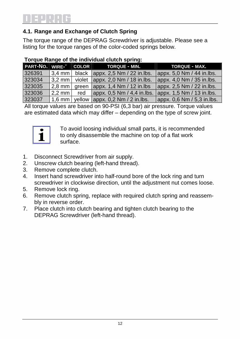
4.1. Range and Exchange of Clutch Spring The torque range of the DEPRAG Screwdriver is adjustable. Please see a listing for the torque ranges of the color-coded springs below. Torque Range of the individual clutch spring: PART-NO. WIRE-∅ COLOR TORQUE - MIN. TORQUE - MAX. 326391 3,4 mm black appx. 2,5 Nm / 22 in.lbs. appx. 5,0 Nm / 44 in.lbs. 323034 3,2 mm violet appx. 2,0 Nm / 18 in.lbs. appx. 4,0 Nm / 35 in.lbs. 323035 2,8 mm green appx. 1,4 Nm / 12 in.lbs appx. 2,5 Nm / 22 in.lbs. 323036 2,2 mm red appx. 0,5 Nm / 4,4 in.lbs. appx. 1,5 Nm / 13 in.lbs. 323037 1,6 mm yellow appx. 0,2 Nm / 2 in.lbs. appx. 0,6 Nm / 5,3 in.lbs. All torque values are based on 90-PSI (6,3 bar) air pressure. Torque values are estimated data which may differ – depending on the type of screw joint.
To avoid loosing individual small parts, it is recommended to only disassemble the machine on top of a flat work surface.
1. Disconnect Screwdriver from air supply. 2. Unscrew clutch bearing (left-hand thread). 3. Remove complete clutch. 4. Insert hand screwdriver into half-round bore of the lock ring and turn
screwdriver in clockwise direction, until the adjustment nut comes loose. 5. Remove lock ring. 6. Remove clutch spring, replace with required clutch spring and reassem-
bly in reverse order. 7. Place clutch into clutch bearing and tighten clutch bearing to the
DEPRAG Screwdriver (left-hand thread).

13
Picture: Change of Clutch Spring
Attention: The claw of the intermediate ring has to engage with the claw in the spindle!
8. The clutch can be adjusted again externally (see section Torque Adjust-ment).
Make sure to screw adjustment (adjusting) nut onto clutch bearing until one line of the thread is visible.
4.2. Torque Adjustment The required torque for the driver can be adjusted externally as follows 1. Disconnect Screwdriver form air supply. 2. Insert hand screwdriver through one of the three slots on the motor hous-
ing into the half-round bore of the lock ring (If necessary, turn clutch using bit).
3. By turning the hand screwdriver clockwise, the torque is reduced and by turning it counter-clockwise, the torque is increased.
Picture: Torque Adjustment
adjustment nut 326111
half-round bore for hand screwdriver
half-round bore
clutch spring

14
4.3. Bit Exchange
Attention: Before exchange of bits, clutch bearing has to be in place and driver needs to be disconnected from air supply.
To change bits, refer to picture Change of bits: • Unscrew spring sleeve 364672 A (Accessories - Optional equipment) (left-
hand thread) – only necessary if a finder is mounted. • Pull the lock sleeve 351890 forward, the bit can now be removed or
inserted.
Picture: Change of bits 4.4. Connection-Possibilities of the Function Control • Use as air pressure outlet during screw-assembly:
- to control driver start and stop, as well as shut-off control of clutch; - as cycle counter of the complete process; each in connection with a PE- Switch or similar.
• Use as air pressure inlet:
- if 6,3 bar (90 PSI) air pressure is given to the function control port, the driver starts rotating at about 15 % of its speed. This will simplify the engagement of bit/socket to fastener (for example when driving hex screws, nuts, etc.)

15
Function Description / Driver Start
Picture: Installation For reversible tools please note: • Right-hand direction of screwdriver will be started by a remote valve via
the air connector on top of the screwdriver and screwdriver will shut off in this direction at the preset torque.
• When providing air to the screwdriver via the connector for left-hand direction (at one side of the screwdriver) screwdriver will rotate at maximum torque. Screwdriver will start running immediately upon providing air to this connector.
• Make sure to always vent the air connector for the opposite direction (otherwise it will result in reduced performance).

16
5 Assembly - Disassembly
Disassembly: (see Spare Parts Drawing)
Prior to disassembly, disconnect equipment from air supply! Only experienced maintenance personnel may assemble or disassemble this equipment.
After repair or maintenance, verify that equipment runs to specification! Principally, use only DEPRAG original spare parts. Otherwise, a reduction in equipment power-output and an increased maintenance-requirement occurs. If NON-DEPRAG parts are installed, DEPRAG is justified to void any existing warranty and liability obligations.
Attention:
Motor- and gearing parts may be damaged if dropped!
For disassembly proceed in the sequence described below: 1. Disconnect driver from air supply. 2. Unscrew clutch bearing (AF 24) together with spring sleeve (AF 19) (left-
hand thread). 3. Remove complete clutch. 4. Disassembly guide bolt by removing hex. nut 826715. 5. Clamp the driver into a vice, utilizing the flats of the flange and unscrew
the sleeve 384494 (AF 24, right-hand thread). 6. Hold motor housing by means of a 24-mm wrench and use the pin
wrench 462122 to remove the valve housing 384469 (right-hand threaded)
7. Remove valve pin. 8. Any suitable arbor may be used to carefully push the motor- and gearing
parts out of the motor housing in direction of the air connection side.
17
Assembly:
Use the DEPRAG Grease 807293 (100-g tube) to grease the ball bearing, needle bearing and gearing parts prior to reassembly.
For assembly proceed logically in reverse order with reference to disassem-bly. Special Repair Tools (Optional Equipment) DESCRIPTION PART NO. Plier (for clutch bearing 356293) 461290 Arbor (for assembly of circlip 800248 onto spindle 351888) 461292 Pin wrench (for valve housing 384469) 462122 Wrench AF 24 (for motor housing) 800406 Wrench AF 8 (for function control line) 800399 Wrench AF 13 (for connection nipple) 800404 5.1. Correct Assembly of Shut-Off Function on Clutch
ATTENTION
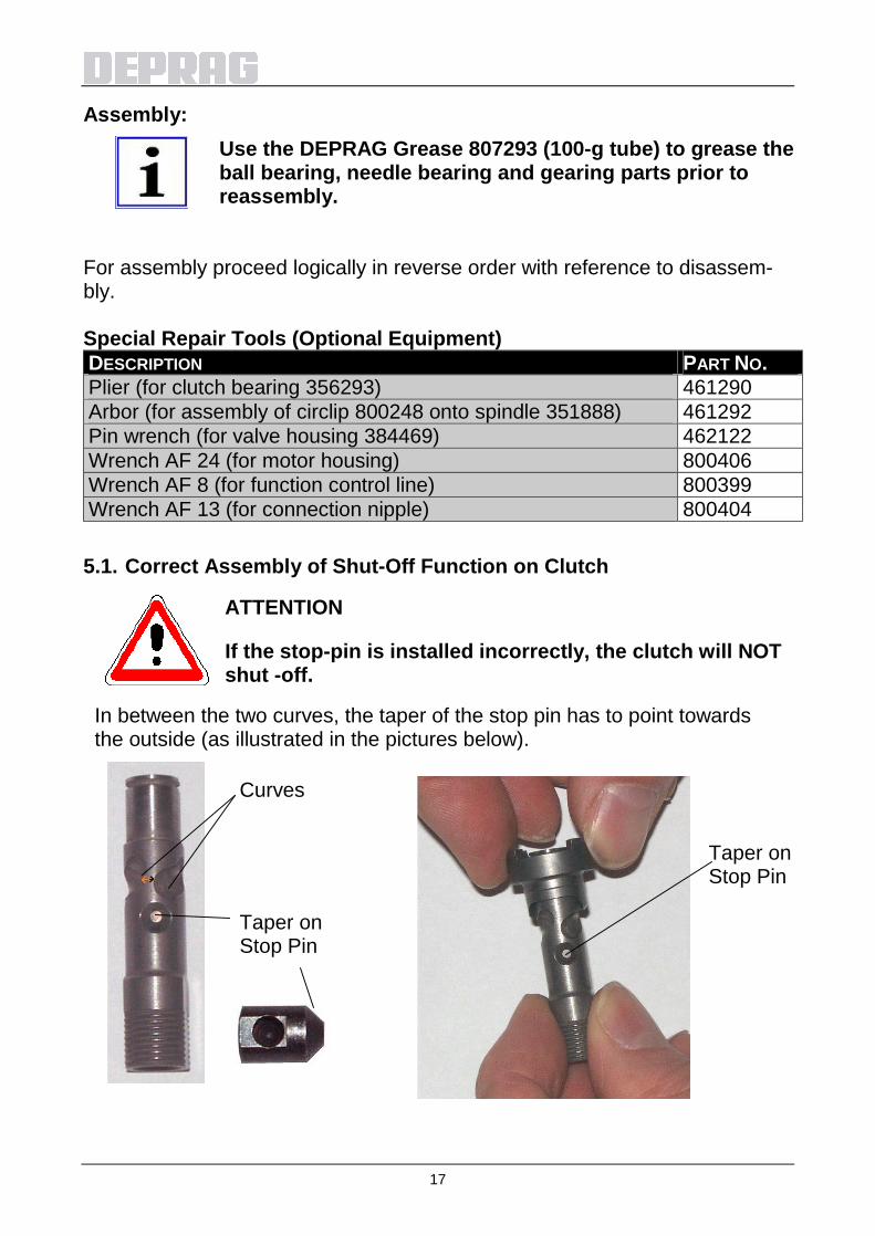
If the stop-pin is installed incorrectly, the clutch will NOT shut -off.
In between the two curves, the taper of the stop pin has to point towards the outside (as illustrated in the pictures below).
Curves
Taper on Stop Pin
Taper on Stop Pin

18
5.2. Spare Part Drawing

19

20

21
5.3. Installation Tips for Screwdriver Spindle

22
6 Maintenance and Upkeep
Testing and maintenance can be provided by Operator, disassembly and re-assembly of the DEPRAG Screwdriver Spindle should be done by experienced maintenance personnel. Incorrect assembly or disassembly can lead to injury of an operator and damage of the tool. The tool requires little maintenance. If the following service rules are observed, the tool will have a long life expectancy and will remain in a safe condition. • Check tool on a regular basis for external damage. • Check your maintenance unit on a regular basis, make sure that sufficient
oil is in the lubricator (if lubrication is used) and that the adjustment is correct. We recommend for your lubricator DEPRAGOL, part 790081 E.
• After cleaning, the gearing parts have to be greased prior to re-assembly, preferably with Grease, part 807293.
• After assembly fill 2 – 3 drops of DEPRAGOL into the air inlet nipple. • If tool are being used with lubrication, we recommend to have tools tested
and cleaned every 12 months (single shift). • If tools are being used without lubrication, we recommend to have tools
tested and cleaned every 6 months (single shift). • Exchange broken or worn plug in tools immediately, for they can cause
injury to the Operator. • If tool malfunctions, we recommend to send the machine to DEPRAG.
6.1. Wear Parts QUANTITY NAME PART NO. 5 Vane 366005/3

23
7 Trouble Shooting
In the case of a malfunction, check and observe all instructions contained in this technical documentation. If necessary, adjust equipment as needed.
Possible faults and their causes are shown below: ERROR REASON SOLUTION Screwdriver does not start
No air, Shut-Off valve is closed
Open Shut-Off valve
Valve pin is too short or missing
Test valve pin length according to picture: Actual size of valve Pin and replace valve pin, if necessary
Clutch is not engaged Mount clutch correctly - refer to: Range- and exchange of clutch spring
Insufficient Power
Air pressure too low Minimum air pressure should be 90 PSI for maximum performance
Restriction in air hose Remove bends or other restrictions
Valve Pin too short Check required length of valve pin according to picture: Actual Size of Valve Pin. If needed, exchange valve pin.
Hose I.D. is too small Use required hose I.D. Screen Support
clogged Clean screen support or exchange with new one
Vanes are worn Exchange vanes Driver does not shut-off or ratchets
Air pressure is too low for required torque value
Maintain air pressure of 90 PSI
Valve Pin is too long Check length of valve pin, either shorten or replace valve pin (picture: Actual Size of Valve Pin)
If necessary, please send tool to DEPRAG for service.

24
Picture: Actual Size of Valve Pin
Attention: When connecting to compressed air supply valve pin may be catapulted out which may cause serious injuries. When verifying the actual size of the valve pin, make sure N O T to hold the screwdriver directed towards yourself or any other person.
Verify the actual size only with compressed air connected!
8 Delivery Capacity
Please check the delivery capacity in regards to its completeness. QUANTITY NAME PART NO. 1 Operating Instruction Booklet 011655EN 1 Pneumatic Screwdriver 386373 A / B / C 1 Hand screwdriver 326240 1 set of Clutch Spring See chapter: Range and Ex-
change of Clutch Spring
25
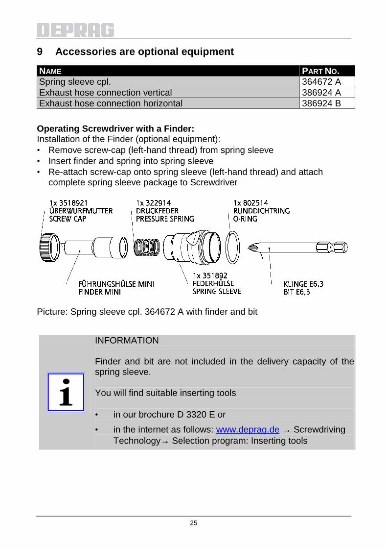
9 Accessories are optional equipment
NAME PART NO. Spring sleeve cpl. 364672 A Exhaust hose connection vertical 386924 A Exhaust hose connection horizontal 386924 B Operating Screwdriver with a Finder: Installation of the Finder (optional equipment): • Remove screw-cap (left-hand thread) from spring sleeve • Insert finder and spring into spring sleeve • Re-attach screw-cap onto spring sleeve (left-hand thread) and attach
complete spring sleeve package to Screwdriver
Picture: Spring sleeve cpl. 364672 A with finder and bit
INFORMATION Finder and bit are not included in the delivery capacity of the spring sleeve. You will find suitable inserting tools • in our brochure D 3320 E or • in the internet as follows: www.deprag.de → Screwdriving
Technology→ Selection program: Inserting tools
26
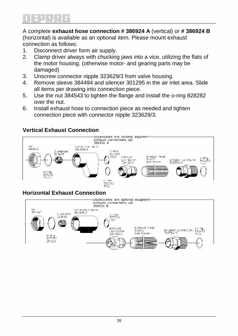
A complete exhaust hose connection # 386924 A (vertical) or # 386924 B (horizontal) is available as an optional item. Please mount exhaust connection as follows: 1. Disconnect driver form air supply. 2. Clamp driver always with chucking jaws into a vice, utilizing the flats of
the motor housing. (otherwise motor- and gearing parts may be damaged)
3. Unscrew connector nipple 323629/3 from valve housing. 4. Remove sleeve 384494 and silencer 301295 in the air inlet area. Slide
all items per drawing into connection piece. 5. Use the nut 384543 to tighten the flange and install the o-ring 828282
over the nut. 6. Install exhaust hose to connection piece as needed and tighten
connection piece with connector nipple 323629/3. Vertical Exhaust Connection
Horizontal Exhaust Connection

27
10 Storage
Unused machines should be stored in a dry, locked area.
11 Technical Data
Manufacturer DEPRAG SCHULZ GMBH u. CO. Address Kurfürstenring 12 - 18 Postfach 1352 D-92224 Amberg D-92203 Amberg Phone 09621/371-0 Fax 09621/371-120 Technical Data: TYPE 347-228-31U 347-328-31U 347-528-31U PART NO. 386373 A 386373 B 386373 C Drive hex. female (DIN 3126) F6,3 (1/4") Weight (kg) 0,91 Air pressure (bar/PSI) 6,3 / 90 Hose I.D. for function control (mm/in.) LW 2,5 / 3/32
Hose I.D. for air supply (mm/in.) LW 5,5 / 7/32
Torque min. (Nm/in.lbs) 0,5 / 5 0,4 / 4 0,3 / 3 max. soft pull-up (Nm/in.lbs) 1,3 / 11 2,6 / 23 4,5 / 40 max. hard pull-up (Nm/in.lbs) 1,8 / 16 3,0 / 26 4,5 / 40 Speed unloaded (rpm) 3000 1150 520 Noise level (dB(A)) 68 Air consumption (m3/min/cfm) 0,3 / 11 Vibration (m/s²) < 2,5

28
12 Disposal
Unused machines should be stored in a dry, locked area. Disassemble the machine for the required disposal complete. Observe local and environmental regulations for the separation and recycling of materials.
Recycle waste oil to avoid environmental contamination!
Waste Oil

29
13 Declaration of Manufacturer
EC-Declaration of Manufacturer in accordance with the CE-Machine-Guideline 98/37/EC,
appendix II B DEPRAG SCHULZ GMBH u. CO. Kurfürstenring 12 – 18 Postfach 1352 D-92204 Amberg D-92203 Amberg declares, that the construction of the Stationary Screwdriver Spindle
347-228-31U 347-328-31U 347-528-31U
its design this tool is meant for integration with another machine. Operation of this tool is not permitted unless the complete unit of mounted machines conforms with the national Protection of Labour Regulations, especially in application of the Provision and Use of Work Equipment Regulations Directive. used standards - EN 292 Amberg, 25.01. 2006

30
14 Service Locations and Authorized Partners
ARGENTINIEN ERIN s.a. Av. Constituyentes 5751 RA-1431 Buenos Aires Tel./Fax: +54 (0) 11 / 4573.1313 AUSTRALIEN De Rossi Industrial Pty. Ltd. Unit 1 – 2 / 600 Liverpool Road Strathfield South, N.S.W. 2136 Tel.: +61 (0)2 / 8732.7200 Fax: +61 (0)2 / 8732.7299 e-mail: [email protected] BELGIEN Aijkens en Zumpolle B.V. Postbus 29 NL-5306 ZG Brakel/Niederlande Tel.: +31 (0)4 18 / 67 18 16 Fax: +31 (0)4 18 / 67 32 17 Internet: http://www.zumpolle.net e-mail: [email protected] BRASILIEN METALFEMA Ltda. Rua Saõ Pedro, 786 Saõ Leopoldo – RS – BRAZIL ZIP 93.010-260 Tel.: +55 (0) 51 / 3592.4050 Fax: +55 (0) 51 / 3590.1856 e-mail: [email protected] CHINA, SUZHOU DEPRAG China DEPRAG Assembly Technologies (Suzhou) Co., Ltd. No. 111, Hong Ye Rd, Blk. 4 Unit D Suzhou 215001, P.R. China Tel.: +86 (0) 512 – 6251 2500 Fax: +86 (0) 512 – 6251 2700 Internet: www.deprag.com.cn e-mail: [email protected] e-mail: [email protected] DÄNEMARK DEPRAG Scandinavia AB Gap Sundins väg 3 SE-63346 Eskilstuna Tel.: +45 (0) 98 57 22 50 Fax: +45 (0) 98 57 22 53 Internet: http://www.deprag.com e-mail: [email protected] DEUTSCHLAND Werk Amberg Kurfürstenring 12-18, D-92224 Amberg Postfach 1352, D-92203 Amberg Tel.: +49 (0) 9621 / 3 71-3 71 Fax: +49 (0) 9621 / 3 71-1 20 Internet: http://www.deprag.com e-mail: [email protected]
ESTLAND Pneumacon OY Läkkisepäntie 4 FI-00620 Helsinki Tel.: +358 (0) 9 / 7288.160 Fax: +358 (0) 9 / 7288.1610 Internet: http://www.pneumacon.fi e-mail: [email protected] e-mail: [email protected] FINNLAND Pneumacon OY Läkkisepäntie 4 FI-00620 Helsinki Tel.: +358 (0) 9 / 7288.160 Fax: +358 (0) 9 / 7288.1610 Internet: http://www.pneumacon.fi e-mail: [email protected] e-mail: [email protected] FRANKREICH DEPRAG S.A.R.L. 30 Z.I. du Ried F-67590 SCHWEIGHOUSE sur Moder Tel.: +33 388 / 06.14.17 Fax: +33 388 / 93.01.08 e-mail: [email protected] GRIECHENLAND D. Panayotidis – J. Tsatsis s.a. 6 Pireos Street – Moschaton- Athen Tel.: +30 (0) 1 / 4810.817-8-9 Fax: +30 (0) 1 / 482 96 73 GROSSBRITANNIEN DEPRAG Ltd. Unit B4, Pegasus Court Ardglen Industrial Estate Whitchurch Hants RG28 7BP Tel.: +44 (0) 1256 895 074 Fax: +44 (0) 1256 895 274 Internet: www.deprag.co.uk e-mail: [email protected] INDIEN LEAPTECH Corporation 812 Cosmos, Sector – 11 CBD Belapur New Mumbai - 400 614 Tel.: +91 / 22 / 2756.2822/2849 Fax: +91 / 22 / 2756.2881 Internet: www.leaptechcorp.com e-mail: [email protected] DELHI office: C-332, Sector – 10 Noida – 201 301 Tel.: +91 / 120 / 253.1393 Fax: +91 / 120 / 253.1060 BANGALORE office: # 53, Anchor Suddagundapalaya C.V. Raman Nagar Bangalore – 560 093 e-mail: [email protected]
IRAN FARA SANAT Co. No. 117, Abzar & Yaragh passage Postcode 1136748173 Tehran Tel.: +98 (0) 21 / 673.2918 / 670.6340 Fax: +98 (0) 21 / 673.4757 NACCARSON AIR TOOLS Co., Ltd. Azadi Ave. No. 625 IR-Tehran 14 588 Tel.: +98 (0) 21 / 66006602 + 66015656 Fax: +98 (0) 21 / 66009451 IRLAND Production Equipment Ltd. Riverside Commercial Estate IRL-Galway Tel.: +353 (0) 91 / 745 100 Fax: +353 (0) 91 / 751 299 e-mail: [email protected] ITALIEN ATAX S.r.l. Via Carolina Romani, 23 I-20091 Bresso/Mi Tel.: +39 02/ 61.03.48.61 Fax: +39 02/ 61.03.48.60 Internet: www.atax.it e-mail: [email protected] JAPAN NIPPON GESCO Ltd. P.O. Box 255 Kyobashi Tokyo Ginza Matsuyoshi Bldg. 17 – 8, 7-Chome, Ginza, Chuo-Ku, Tokyo Tel.: +81 (0) 3 / 3542.2400 Fax: +81 (0) 3 / 3542.2420 e-mail: [email protected] KOREA (Süd) Handwerkzeuge DONG WON POWER-TECH.INC. 108-10 Moonjung-Dong Songpa-Ku Seoul, Korea Tel.: +82 (0) 2 / 409.1344 Fax: +82 (0) 2 / 409.1345 e-mail: [email protected] Schraubtechnik Fatec Co.Ltd. #717 LG Palace B/D 165-8 Dongkyo-dong Mapo-gu Seoul, Korea Tel.: +82 (0) 2 / 2 688.2152 Fax: +82 (0) 2 / 2 688.2893 e-mail: [email protected] e-mail: [email protected]

31
ITALY ATAX S.r.l. Via Carolina Romani, 23 I-20091 Bresso/Mi Tel.: 0039 02/ 61.03.48.61 Fax: 0039 02/ 61.03.48.60 e-mail: [email protected] Internet: www.atax.it JAPAN NIPPON GESCO Ltd. P.O. Box 255 Kyobashi Tokyo Ginza Matsuyoshi Bldg. 17 – 8, 7-Chome, Ginza, Chuo-Ku, Tokyo Tel.: +81 (0) 3 / 3542.2400 Fax: +81 (0) 3 / 3542.2420
e-mail: [email protected] KOREA (South) Handtools DONG WON POWER-TECH.INC. 108-10 Moonjung-Dong Songpa-Ku Seoul, Korea Tel.: +82 (0) 2 / 409.1344 Fax: +82 (0) 2 / 409.1345 e-mail: [email protected] Screwdriving / Assembly Technology Fatec Co.Ltd. #717 LG Palace B/D 165-8 Dongkyo-dong Mapo-gu Seoul, Korea Tel.: +82 (0) 2 / 2 688.2152 Fax: +82 (0) 2 / 2 688.2893 e-mail: [email protected] e-mail: [email protected] LITHUANIA HIDROTEKA P.O. Box 572 LT-3028 KAUNAS Tel.: +370 (0) 37 / 352195 Fax: +370 (0) 37 / 351952 e-mail: [email protected]
LUXEMBOURG Comptoir Technique et Industriel 321, Route d´Arlon L-8011 Strassen Penang, MALAYSIA Tel.: +352 / 31 31 40 Fax: +352 / 31 31 95 MALAYSIA FI INNOVATION ENTERPRISE 175, MK D Jalan Bahru Balik Pulau 11000 Penang, MALAYSIA Tel. +60/13/ 449.0386 / +60/16/ 403.6797 Fax: +60/4/ 866.0785 e-mail: [email protected]
NETHERLANDS Zumpolle B.V. Postbus 29 NL-5306 ZG Brakel/Niederlande Tel.: +31 (0) 4 18 / 67 18 16 Fax: +31 (0) 4 18 / 67 32 17 Internet: http://www.zumpolle.net
e-mail: [email protected] NORWAY Deprag Scandinavia AB Gap Sundins väg 3 SE-63346 Eskilstuna Universal Import Tel.: +47 (0) 2 / 2681.530
Fax: +47 (0) 2 / 2199.127 POLAND ELKREM SPOLKA Z O.O. ul. Wielki Row 40B 87-100 Torun Tel.: +48 / 56 / 662.3881 Fax: +48 / 56 / 662.3882 e-mail: [email protected] PORTUGAL Anibal Pires Lda. A.P. 23 E.N. 1 – Mourisca do Vouga P-3750 TROFA AGD Tel.: +351 (0) 234 / 646.820 Fax: +351 (0) 234 / 646.815 Internet: http:// www.anibalpires.pt e-mail: [email protected] SINGAPORE Testel Systems Pte Ltd 1200 Depot Road # 04-07/09 Singapore 109675 Tel.: +65 / 6271-3688 Fax: +65 / 6271-8866 Internet: http://www.testel.com.sg e-mail: [email protected] SLOVENIA MB-NAKLO D.O.O. Toma Zupana 16 SLO-4202 NAKLO Tel.: +386 (0) 4 / 277 17 00 Fax: +386 (0) 4 / 277 17 17 e-mail: [email protected] SPAIN ALCOTAN SISTEMAS S.A. p° de la Direccion, nmro. 95, local E-28039 Madrid Tel.: +34 91 / 311.17.84 + 311.18.01 Fax: +34 91 / 311.60.53 e-mail: [email protected]
BARCELONA office: Passeig de la Mare de Déu del Coll, 122-124 E-08023 Barcelona
Tel.: +34 93 / 2 85 50 34 SWEDEN DEPRAG Scandinavia AB Gap Sundins Väg 3 S-633 46 Eskilstuna Tel.: +46 (0) 16-12 61 10 Fax: +46 (0) 16-13 31 88 Internet: http://www.deprag.se e-mail: [email protected] SWITZERLAND LIMATEC Automation AG Burgunderstr. 13 CH-4562 Biberist Tel.: +41 (0) 32 / 6542900 Fax: +41 (0) 32 / 6542901 Internet: http://www.limatec.ch e-mail: [email protected] TAIWAN I HEN MACHINE Co.Ltd. 6F-9, No. 12, Lane 609, Sec. 5 Chung-Hsin Road, San-Chung City 241 Taipei Hsen Tel.: +886 (0) 2 / 2999.6766 Fax: +886 (0) 2 / 2999.6236 TURKEY MEKA AUTOMOTIVE ASSEMBLY EQUIPMENTS Dicle Caddesi, Tunca Sokak No : 6 Beysukent - Beytepe - Ankara - TURKEY Tel.: +90 / 312 / 236 2558 Tel.: +90 / 312 / 236 2559 Fax: +90 / 312 / 236 0991 Internet: www.me-ka-assembly.com e-mail: [email protected] USA, MEXICO, CANADA DEPRAG INC. 645 Hembry St. / P.O. Box 1554 Lewisville, TX 75057-4726 Tel.: +1 / 972 / 221 – 8731 Fax: +1 / 972 / 221 – 8163 Toll Free: (800) 4 DEPRAG Internet: http://www.deprag.com e-mail: [email protected] VENEZUELA Suministros Tecnicos SUMTEC C.A. Av. Francisco de Mirando, Centro Plaza Torre C, Piso 16, Officina C16 A-B Urb. Los Palos Grandes Caracas 1060 Tel.: +58 (0) 212 – 28 56 41 0 Fax.: +58 (0) 212 – 28 51 94 7

DEPRAG SCHULZ GMBH u. CO. Postfach 1352, D-92203 Amberg Kurfürstenring 12-18, D-92224 Amberg ( (09621) 371-0 Fax (09621) 371-120 Internet: http://www.deprag.com e-mail: [email protected]
Jan-
06
Änd
erun
gen
vorb
ehal
ten
/ Tec
hnic
al a
ltera
tions
rese
rved