miscellaneous: br2/type 43/uhf/imp/ump
TRANSCRIPT

SIMPLIFICATION IS OUR INNOVATON Visit www.radiall.com for more information
SECTION 14
MISCELLANEOUS: BR2/TYPE 43/UHF/IMP/UMP
R605/R214/R155/R107

14-3Go online for data sheets & assembly instructions. Visit www.radiall.com and enter the part number.
SIMPLIFICATION IS OUR INNOVATION
TYPE 43Introduction . . . . . . . . . . . . . . . . . . . . . . . . . . . . . . . . . . . . . . . . . . . . . . . . . . . . . . . . . . . . . . . . . . . . . . . . . . . . . . . . . . . . . . . . . . . . . . . . . . . . . . . . . . . . . . . . . . . . . 14-4Interface . . . . . . . . . . . . . . . . . . . . . . . . . . . . . . . . . . . . . . . . . . . . . . . . . . . . . . . . . . . . . . . . . . . . . . . . . . . . . . . . . . . . . . . . . . . . . . . . . . . . . . . . . . . . . . . . . . . . . . . . 14-4Characteristics . . . . . . . . . . . . . . . . . . . . . . . . . . . . . . . . . . . . . . . . . . . . . . . . . . . . . . . . . . . . . . . . . . . . . . . . . . . . . . . . . . . . . . . . . . . . . . . . . . . . . . . . . . . . . . . . . 14-5 Panel drilling ..................................................................................................................................................................14-8
STANDARD DENSITYPlugs . . . . . . . . . . . . . . . . . . . . . . . . . . . . . . . . . . . . . . . . . . . . . . . . . . . . . . . . . . . . . . . . . . . . . . . . . . . . . . . . . . . . . . . . . . . . . . . . . . . . . . . . . . . . . . . . . . . . . . . . . . . . 14-6Sockets . . . . . . . . . . . . . . . . . . . . . . . . . . . . . . . . . . . . . . . . . . . . . . . . . . . . . . . . . . . . . . . . . . . . . . . . . . . . . . . . . . . . . . . . . . . . . . . . . . . . . . . . . . . . . . . . . . . . . . . . . . 14-6Receptacles . . . . . . . . . . . . . . . . . . . . . . . . . . . . . . . . . . . . . . . . . . . . . . . . . . . . . . . . . . . . . . . . . . . . . . . . . . . . . . . . . . . . . . . . . . . . . . . . . . . . . . . . . . . . . . . . . . . . . 14-6
HIGH DENSITYPlugs . . . . . . . . . . . . . . . . . . . . . . . . . . . . . . . . . . . . . . . . . . . . . . . . . . . . . . . . . . . . . . . . . . . . . . . . . . . . . . . . . . . . . . . . . . . . . . . . . . . . . . . . . . . . . . . . . . . . . . . . . . . . 14-7U links . . . . . . . . . . . . . . . . . . . . . . . . . . . . . . . . . . . . . . . . . . . . . . . . . . . . . . . . . . . . . . . . . . . . . . . . . . . . . . . . . . . . . . . . . . . . . . . . . . . . . . . . . . . . . . . . . . . . . . . . . . . 14-8
ULTRA HIGH DENSITYPlugs ...............................................................................................................................................................................14-7
IMPIntroduction ...................................................................................................................................................... 14-9 to 14-10Characteristics ..............................................................................................................................................................14-11Board to board connectors ...........................................................................................................................................14-12Receptacle packaging ...................................................................................................................................................14-13Assembly instructions ..................................................................................................................................................14-12
UMPCharacteristics ..............................................................................................................................................................14-11Receptacles ...................................................................................................................................................................14-14Pigtails ..........................................................................................................................................................................14-14Cable assemblies ..........................................................................................................................................................14-14Tools and accessories ...................................................................................................................................................14-15Assembly instructions ..................................................................................................................................................14-16
BR2Interface ........................................................................................................................................................................14-17Characteristics ..............................................................................................................................................................14-17Plugs .............................................................................................................................................................................14-18Jacks .............................................................................................................................................................................14-18Receptacles ...................................................................................................................................................................14-19Caps ..............................................................................................................................................................................14-19Gasket ...........................................................................................................................................................................14-20Panel drilling ................................................................................................................................................................14-20
UHFInterface ........................................................................................................................................................................14-21Characteristics ..............................................................................................................................................................14-21Plugs .............................................................................................................................................................................14-22Receptacles ...................................................................................................................................................................14-22Adapter ..........................................................................................................................................................................14-22
Contents
SECT
ION
14 T
ABL
E O
F CO
NTE
NTS

14-4 Go online for data sheets & assembly instructions. Visit www.radiall.com and enter the part number.
SIMPLIFICATION IS OUR INNOVATIONTY
PE 4
3
GENERAL• Standard coaxial connectors• Reliable lock coupling• 3 types: Standard Density (12.7mm)
High Density (10mm) Ultra High Density (9mm)
APPLICABLE STANDARDS• BS9210 F0022
APPLICATIONS• Telecom DDF (Digital Distribution Frames)
75Ω DC - 3 GHz
PLUG JACK
Letter mm inch
min. max. min. max. A DIA 6.20 6.23 .244 .245B DIA 5.25 NOM .207 NOMC DIA 3.4 3.475 .134 .137D DIA 0.48 0.52 .019 .02E DIA 0.125 0.225 .005 .009F DIA 5.97 6.02 .235 .237
G 3.5 3.55 .138 .14H 2.4 2.55 .095 .1I 0.05 0.175 .002 .007J 0.00 0.10 0.00 .004K 0.25 0.35 .01 .014L 1.35 - .053 -M - 2.05 - .081N - 0.18 - .007O 0.58 NOM .023 NOMP 0.15 0.25 .006 .01R 0.05 0.15 .002 .006S - 0.13 - .005T 0.1 0.2 .004 .008
Letter mm inch
min. max. min. max. A DIA 6.31 6.36 .248 .25B DIA 5.25 NOM .207 NOMC DIA 3.22 3.30 .127 .13
D 3.2 3.53 .126 .139E 3.63 3.83 .143 .151F - 1.8 - .071G 3.61 3.77 .142 .148H 0.23 0.38 .009 .015I 0.23 0.48 .009 .019J 1.475 1.97 .058 .078
Introduction
Interface
14-5Go online for data sheets & assembly instructions. Visit www.radiall.com and enter the part number.
SIMPLIFICATION IS OUR INNOVATION
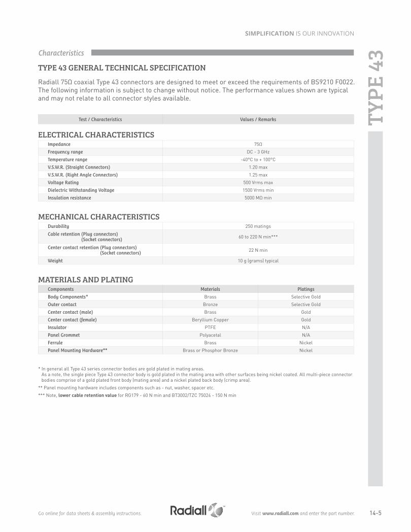
TYPE 43 GENERAL TECHNICAL SPECIFICATION
Radiall 75Ω coaxial Type 43 connectors are designed to meet or exceed the requirements of BS9210 F0022. The following information is subject to change without notice. The performance values shown are typical and may not relate to all connector styles available.
ELECTRICAL CHARACTERISTICS Impedance 75Ω
Frequency range DC - 3 GHz
Temperature range -40°C to + 100°C
V.S.W.R. (Straight Connectors) 1.20 max
V.S.W.R. (Right Angle Connectors) 1.25 max
Voltage Rating 500 Vrms max
Dielectric Withstanding Voltage 1500 Vrms min
Insulation resistance 5000 MΩ min
MECHANICAL CHARACTERISTICSDurability 250 matings
Cable retention (Plug connectors) (Socket connectors)
60 to 220 N min***
Center contact retention (Plug connectors) (Socket connectors)
22 N min
Weight 10 g (grams) typical
MATERIALS AND PLATING Components Materials Platings
Body Components* Brass Selective Gold
Outer contact Bronze Selective Gold
Center contact (male) Brass Gold
Center contact (female) Beryllium Copper Gold
Insulator PTFE N/A
Panel Grommet Polyacetal N/A
Ferrule Brass Nickel
Panel Mounting Hardware** Brass or Phosphor Bronze Nickel
* In general all Type 43 series connector bodies are gold plated in mating areas. As a note, the single piece Type 43 connector body is gold plated in the mating area with other surfaces being nickel coated. All multi-piece connector bodies comprise of a gold plated front body (mating area) and a nickel plated back body (crimp area).
** Panel mounting hardware includes components such as - nut, washer, spacer etc.
*** Note, lower cable retention value for RG179 - 60 N min and BT3002/TZC 75024 - 150 N min
Test / Characteristics Values / Remarks
Characteristics
TYPE
43

14-6 Go online for data sheets & assembly instructions. Visit www.radiall.com and enter the part number.
SIMPLIFICATION IS OUR INNOVATION
Cable group Cable group dia. BT Reference Part numberDimensions
PackagingA B C D
BT3002 3.6/75/D S 43/5 FS R214 083 922 0.36 4.47 3.2 20 pieces
STRAIGHT SOCKETS CRIMP TYPE FOR FLEXIBLE CABLES
Part number Panel drilling PackagingR214 553 000 P02 Unit
STRAIGHT BULKHEAD RECEPTACLE WITH SOLDER POT
Plugs, Sockets and Receptacles - Standard Density
BT Reference Part number Panel drilling PackagingP 43 / 1 D R214 426 704 P01 100 pieces
STRAIGHT PCB PLUG RECEPTACLES
TYPE
43

14-7Go online for data sheets & assembly instructions. Visit www.radiall.com and enter the part number.
SIMPLIFICATION IS OUR INNOVATION
Cable group Cable group dia. BT Reference Part numberDimensions Panel
drilling PackagingA B C D
RG179 2.6/75/S HDC 43/4 GTIS R214 318 702 0.38 1.73 3.2535 P03 20 piecesBT3002 3.6/75/D HDC 43/5 GTIS R214 318 722 0.36 2.10 4.47
RA7000 4.5/75/D HDC 43/7 GTIS R214 325 742 0.69 3.00 5.48
STRAIGHT PLUGS CRIMP TYPE FOR FLEXIBLE CABLES
Cable group Cable group dia. BT Reference Part numberDimensions
PackagingA B C D
RG179 2.6/75/S HDC 43/4FS R214 088 902 0.38 1.73 3.25 3220 pieces
BT3002 3.6/75/D HDC 43/5FS R214 088 922 0.35 2.10 4.47 30
STRAIGHT SOCKETS CRIMP TYPE FOR FLEXIBLE CABLES
Plugs - High Density, Sockets and Ultra High Density
Cable group Cable group dia. BT Reference Part number Fig. Panel drilling PackagingRG179 2.6/75/S UHDC 43/4 GTIS R214 320 702 1
P04 20 piecesBT3002 3.6/75/D UHDC 43/5 GTIS R214 320 722 2
STRAIGHT PLUG CRIMP TYPE FOR FLEXIBLE CABLES
Fig. 2Fig. 1
TYPE
43

14-8 Go online for data sheets & assembly instructions. Visit www.radiall.com and enter the part number.
SIMPLIFICATION IS OUR INNOVATION
mm
Maxi mini
A 7.35 7.05
A
BT Reference Part number Fig. PackagingU link 10A R214 797 703 1
50 pieces
U link 10B R214 798 703 2U link 13A R214 790 703 3U link 13B R214 791 703 4U link 9A R214 797 723 5U link 9B R214 798 723 6
U LINKS
Fig. 1
Fig. 4 Fig. 5 Fig. 6
Fig. 2 Fig. 3
U Links - High Density
Panel Drilling
PO1 PO2
PO4
PO3
mm
Maxi mini
A 1.5 1.2
B 2.0 1.7
C 5.1 5.06
A DIA
B DIA
4 holes
C
mm
Maxi mini
A 8.04 7.94
B 7.5 7.4
A
B
mm
Maxi mini
A 7.55 7.5
A
TYPE
43

14-9Go online for data sheets & assembly instructions. Visit www.radiall.com and enter the part number.
SIMPLIFICATION IS OUR INNOVATION
IMPOne piece connector
MCX 2 coaxial
connectors
MMS3 coaxial
connectors
IMP/
UM
PIntroduction
Radiall introduced the MMP contact technology (Micro Miniature Pressure) in 2001 to meet the needs of the telecommunication industry for ultra low profile and cost effective board connectors. The MMP technology can be found in 2 product lines:
• IMP series: RF Board-to-Board application • UMP series: RF board to wire application
BOARD-TO-BOARD APPLICATION
The UMP series (Ultra Miniature Pressure contact) consists of 1 coaxial plug and 1 SMT edge receptacle.
MCX series
UMP series
IMP
BOARD TO WIRE APPLICATION
UMP
The IMP series (Interconnect Micro miniature Pressure contact) consists of 1 coaxial connector when usually the same application requires either 2 coaxial connectors (a male SMT receptacle and a female SMT receptacle), or 3 coaxial connectors (2 SMT receptacles and an adapter).

14-10 Go online for data sheets & assembly instructions. Visit www.radiall.com and enter the part number.
SIMPLIFICATION IS OUR INNOVATION
IMP PRODUCT FEATURES• Cost effective solution: one piece connector only• High density• Lightweight connector: (example 0.02 g for the IMP 2 mm)• Low profile for a board-to-board coaxial connections (2 mm)
UMP PRODUCT FEATURES• Low profile: 2 mm and 3 mm• Small space for connection: needs only 2 mm of height• Cost effective solution: 1 coax connector only• Large cable range from 0.8 to 2.6 mm• High durability, up to 10,000 cycles
UMP TYPE OF MATING:• Lock: - Can only be disconnected using a tool - Number of matings 100 - Withstands severe vibrations • Snap-on: - Number of matings 3000• Snap-on: - Number of matings 10,000 - For test applications
Plug exist with the 3 types of mating:
APPLICATIONSIMP and UMP series can be used for board-to-board and board-to-antenna applications:
• WLAN • Automotive • RFID• GPS receivers • Handheld radios
IMP INSTALLATIONThe distance between the 2 boards should be precisely measured by a mechanical device (such as spacers). Contact Radiall for support regarding the layout in your particular application. Application notes are available upon request.
IMP PRODUCT RANGEIMP is available in 2 mm board-to-board distance. Other heights can be developed upon request.
Introduction
IMP/
UM
P
Lock
Snap-on
Slide-on

14-11Go online for data sheets & assembly instructions. Visit www.radiall.com and enter the part number.
SIMPLIFICATION IS OUR INNOVATION
ELECTRICAL CHARACTERISTICS IMP UMP
Impedance 50Ω
Frequency range DC-6 GHz
V.S.W.R. Max 1.3 1.05 + 0.03F (mated connectors)Insertion Loss (dB) 0.2 √F (GHz)RF Leakage -40dB min at 2 GHzInsulation resistance 3000MΩ 1000MΩ min
Contact resistance (depending on PC board)
• Center contact• Outer contact
60 mΩ10 mΩ
Working voltage 100 VRMS
Dielectric withstanding voltage 350 VRMS
Power at sea level, at 20°C 20 W (at 3 GHz) 50 W (at 1.8 GHz)
MECHANICAL CHARACTERISTICS
Durability > 20- Lock: 100
- Snap-on: 3000- Slide-on: 10,000
Weight (g) 0.02 - Receptacle: 0.03- Plug: 0.08
Axial misalignment from nominal board to board distance in mm (inch)
±0.2 (.008) N/A
Radial misalignment in mm (inch) 0.2 (.008) N/A
Force to engage - 5N
Cable retention force - 20N - 100N
Sine vibrations - IEC 68-2-6
Random vibrations - IEC 68-2-36
Shocks - IEC 68-2-29
Retention on test board - 20N min
ENVIRONMENTAL CHARACTERISTICS Temperature range -40 / +90°C
MATERIALSBody/outer contact
Beryllium copper-Plug: Brass
-Receptacle: Berylium copper
Center contact Brass (plug only)
Insulator Polyethercetone PTFE
PLATINGBody
GoldContact
Values / Remarks
Characteristics
IMP/
UM
P
14-12 Go online for data sheets & assembly instructions. Visit www.radiall.com and enter the part number.
SIMPLIFICATION IS OUR INNOVATIONIM
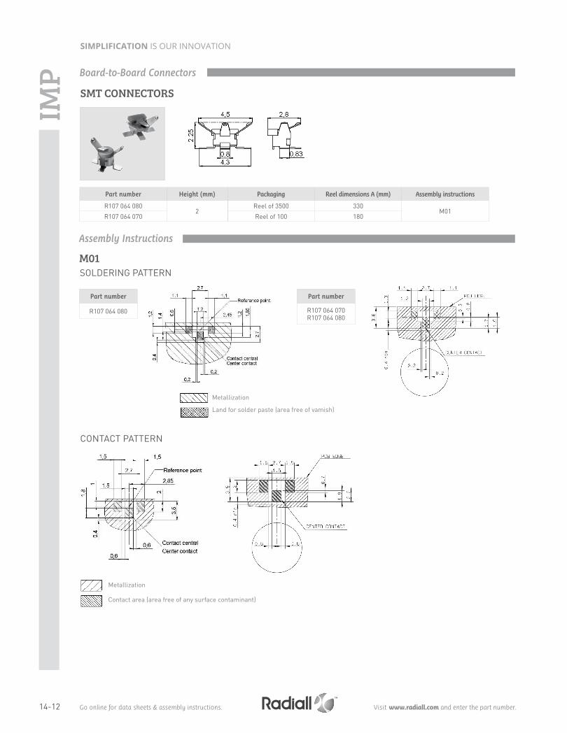
P Board-to-Board Connectors
SMT CONNECTORS
Part number Height (mm) Packaging Reel dimensions A (mm) Assembly instructions
R107 064 0802
Reel of 3500 330M01
R107 064 070 Reel of 100 180
SOLDERING PATTERN
Part number
R107 064 070R107 064 080
Part number
R107 064 080
M01
Metallization
Land for solder paste (area free of vamish)
Assembly Instructions
CONTACT PATTERN
Metallization
Contact area (area free of any surface contaminant)

14-13Go online for data sheets & assembly instructions. Visit www.radiall.com and enter the part number.
SIMPLIFICATION IS OUR INNOVATION
IMPReceptacle Packaging
IMP H2
The following pick and place equipment and associated nozzles were successfully tested for the IMP:A) FUJI: QP-242/MODULE TYPE
QP-242 IMP MOUNT MODULE NAME: TYPE BI-612 IMP NOZZLE PART N°: I-S12B-013-100 (NOZZLE PIE 1.3)
B) PANASONIC: MSF type machine NOZZLE PART N°: 10 807 GH 810
For other equipment, please contact your supplier to define equivalent nozzles.
PROCEDURE FOR USE OF SMT NOZZLE FOR RECEPTACLE

14-14 Go online for data sheets & assembly instructions. Visit www.radiall.com and enter the part number.
SIMPLIFICATION IS OUR INNOVATIONU
MP
SMT RECEPTACLES
PIGTAILS
BETWEEN SERIES CABLE ASSEMBLIES
Fig. 1
Fig. 1
Fig. 2
Fig. 2
UMP type Part numberDimensions (mm)
Finish Packaging Reel dimensions (mm)
Assembly instructionsA B C
H2 R107 003 010 3.6 2 2.05Gold 100 pieces 180 M02
H3 R107 303 040 5.5 3 2.95
Cable Cable group UMP type Mating type Part number Fig.Dimensions (mm)
PackagingA B
C291 050 066 1/50/S H2Lock R285 020 202 1 1.74
4 100 piecesSnap-on R285 020 212 2 1.65
C291 170 017 2.6/50/S H3 Lock R285 020 401 1 2.84
Cable Cable group UMP type Mating type Part number Fig. Series Packaging
C291 050 066 1/50/S H2Lock R285 025 202 1
UMP/SMA 20 piecesSnap-on R285 025 212 2
C291 170 017 2.6/50/S H3 Lock R285 025 401 1
Snap-on
Snap-on
Lock
Lock
Receptacles, Pigtails and Cable Assemblies

14-15Go online for data sheets & assembly instructions. Visit www.radiall.com and enter the part number.
SIMPLIFICATION IS OUR INNOVATION
UM
P
PRODUCTION LINE TEST ADAPTER: UMP - SMA FEMALE (to be used with lock and snap pigtails only)
EXTRACTION TOOL (for lock version only)
INSERTION TOOL (optional)
Part number Connector height (mm) Packaging
R107 009 901 H 2Unit
R107 009 903 H 3
Part number Photo Note To disconnect Packaging
R282 867 020 1 Axial disconnection H 210 pieces
R282 867 030 2 Lateral disconnection H 3
Part number
R282 203 020
Photo 1 Photo 2
For measurement and test purposes. Packaging: Unit
The 2 disconnection tools allows axial and lateral disconnections depending on the occupied space on the PCB.
This optional tool allows you a more precise connection in a limited space.
Packaging: Unit
Tools and Accessories

14-16 Go online for data sheets & assembly instructions. Visit www.radiall.com and enter the part number.
SIMPLIFICATION IS OUR INNOVATION
H2 type receptacle
H3 type receptacle
RECEPTACLE SOLDERING PATTERNS FOR COPLANAR LINE
Part number
R107 003 010
Part number
R107 303 040
M02
Gold over Nickel prefered for solder pasteGold can be replaced by tin lead (see test report SC2000.02.6587)
Gold over Nickel contact area free of any surface contaminant
Ground + varnish
PCB thickness (mm)
Coplanar ligne A (mm)
0.8 0.183
1.0 0.190
1.2 0.195
1.6 0.20
Assembly Instructions
UM
P
SMT NOZZLE
Automated pick and place machines use standard tooling to peel the antistatic film off. Sometimes the "A" dimension of this tool is shorter than the overall "B" width between the two legs of the receptacle. There is therefore a risk for the two legs being deformed while they pass through the tool during the suction operation. The user must then widen the "A" dimension of the peeling tool.

14-17Go online for data sheets & assembly instructions. Visit www.radiall.com and enter the part number.
SIMPLIFICATION IS OUR INNOVATION
Letter mm inch
min. max. min. max. A DIA 9.78 9.91 .385 .390B DIA 6.70 6.77 .264 .267C DIA 1.31 1.36 .052 .054
D 2.95 3.05 .116 .120E 7.6 7.9 .299 .311F -0.05 0.15 .002 .006G 0.85 1.55 .033 .061H 1.55 1.65 .061 .065
Letter mm inch
min. max. min. max. A DIA 10.93 11.09 .430 .437B DIA 9.60 9.70 .378 .382C DIA 8.79 9.04 .346 .356D DIA 8.31 8.46 .327 .333E DIA 8.09 8.15 .319 .321F DIA 5.9 6.0 .232 .236 G DIA 1.4 1.45 .055 .057
H 2.95 3.05 .116 .120 I -0.1 0.8 -.004 .031 J 5.3 5.7 .209 .224 K 7.05 7.35 .278 .289 L 8.36 8.46 .327 .335M 1.91 2.06 .075 .081 N 1.45 1.55 .057 .061 O 0.35 0.85 .014 .033
PLUG JACK
Bayonnet lock coupling with polarization
ELECTRICAL AND ENVIRONMENTAL CHARACTERISTICSDielectric withstanding voltage
Between pins Between pins and body 1.500 volts RMS, 50 Hz
Maximum intensity 3.5 Amp
Insulation resistanceBetween pins
Between pins and body > 105 MΩ
Contact resistance < 1 mΩ at 1 Amp
Capacity at 1 MHzBetween pins
Between pins and body< 1.3 pF< 3.2 pF
Frequency range DC - 0.5 GHzTemperature range -40 +100° C
MATERIALSAll metal parts under stress Beryllium copperOther metal parts BrassInsulators Polyamide and diallyphtalateGaskets Neoprene
Interface
Characteristics
BR2

14-18 Go online for data sheets & assembly instructions. Visit www.radiall.com and enter the part number.
SIMPLIFICATION IS OUR INNOVATION
STRAIGHT PLUGS FOR ARMOUR TWINAXIAL CABLE
RIGHT ANGLE PLUG
STRAIGHT JACKS
Cable group dia Part number Dimensions (mm) A
Twinaxial 4 R605 004 000 4.6Twinaxial 5 R605 005 000 5.6Twinaxial 6 R605 006 000 6.6
Cable group dia Part number Fig. Panel drilling Note
Twinaxial 6R605 206 000 1
P01-
R605 256 000 2 Square flange
Cable group dia Part number
Twinaxial 6 R605 156 000
Fig. 1 Fig. 2
Plugs and Jacks
BR2

14-19Go online for data sheets & assembly instructions. Visit www.radiall.com and enter the part number.
SIMPLIFICATION IS OUR INNOVATION
RECEPTACLES
PCB RECEPTACLES
CAPS
Part number Fig. Panel drilling Note
R605 400 000 1 P02 Square flangeR605 550 000
2 P04Rear fixing
R605 550 020 Front mountingR605 600 000 3 P05 Waterproof
Part number Panel drilling
R605 440 000 P03
Fig. 1 Fig. 3Fig. 2
Fig. 1 Fig. 3Fig. 2
Part number Fig. NoteR141 802 000 1 MaleR141 812 000 2 Male with chainR141 842 000 3 Female with chain
Receptacles and Caps
BR2

14-20 Go online for data sheets & assembly instructions. Visit www.radiall.com and enter the part number.
SIMPLIFICATION IS OUR INNOVATION
PO1
PO4
PO2
PO5
PO3
GASKETPart number
R280 503 000
mm
Maxi mini
A (R. Mount) 11.3 11.2
A (F. Mount) 13 12.9
B 2.7 2.6
C 12.75 12.65
B DIA
4 holes
A DIA
C
mm
Maxi mini
A 11.3 11.2
B 2.7 2.6
C 12.75 12.65
B DIA
4 holes
A DIA
C
Gasket
Panel Drilling
BR2

14-21Go online for data sheets & assembly instructions. Visit www.radiall.com and enter the part number.
SIMPLIFICATION IS OUR INNOVATION
UH
F
ELECTRICAL CHARACTERISTICS Impedance 50Ω
Maximum frequency range 500 MHz
Test voltage (At sea level) 2000 V rms - 50 Hz
Working voltage (At sea level) 750 V
Insulation resistance (Under 500 V) ≤ 5 GΩ
Contact resistance • Centre contact • Outer contact
5 mΩ max5 mΩ max
MECHANICAL CHARACTERISTICSMating cycles 500
ENVIRONMENTAL CHARACTERISTICSTemperature range • PTFE
• Bakelite • Styramic
-55°C to + 155°C-40°C to + 165°C-40°C to + 70°C
Salt spray 48 Hrs
MATERIALS Contacts and interfaces Heat treated beryllium copper
Other parts Brass
Insulator PTFE (T) - bakelite (B) or styramic (St.)
Gaskets Neoprene or silicone rubber
All dimensions are given in mm.
Test / Characteristics Values / Remarks
Characteristics
PLUG JACK
Letter mm inch
min. max. min. max. A DIA 11.56 12.22 .455 .481B DIA 16.00 --- .630 ---C DIA 13.92 --- .548 ---D DIA --- 3.35 --- .132E DIA 3.912 4.013 .154 .158
F --- 11.10 --- .437G --- 9.91 --- .390H 8.76 --- .335 ---I 1.19 4.27 .047 .168J 0.00 --- .000 ---
Letter mm inch
min. max. min. max. A DIA 11.56 12.22 .455 .481B DIA 14.00 14.25 .551 .561
C 11.10 --- .437 ---D 7.87 --- .310 ---E 1.02 --- .040 ---F 0.03 --- .001 ---G 1.19 1.96 .047 .077
Interface

14-22 Go online for data sheets & assembly instructions. Visit www.radiall.com and enter the part number.
SIMPLIFICATION IS OUR INNOVATION
STRAIGHT PLUGS
Cable group Cable group dia. Part number Fig. Note
RG213 / RG393 / RG11 / RG12 / RG144 10/50+75ΩR155 003 000 1
Insulator: PTFER155 005 000 2
Fig. 1 Fig. 2
Plugs, Receptacles and Adapter
Part number Fig. Panel drilling Note
R155 405 000 1 P01 Square flange - Solder pot - Insulator: PTFE
R155 560 000 2 P02 Bulkhead - Solder pot - Insulator: PTFE
RECEPTACLES
Fig. 1 Fig. 2
UH
F

14-23Go online for data sheets & assembly instructions. Visit www.radiall.com and enter the part number.
SIMPLIFICATION IS OUR INNOVATION
NOT
E

14-24 Go online for data sheets & assembly instructions. Visit www.radiall.com and enter the part number.
SIMPLIFICATION IS OUR INNOVATIONN
OTE