mission analysis aspects for earth observations missions · mission analysis aspects for earth...
TRANSCRIPT

MISSION ANALYSIS ASPECTS FOR
EARTH OBSERVATIONS MISSIONS
Antonio Ciccolella - ESA
Summer School Alpbach
29 July 2010
From where all starts from…Newton Laws and the restricted two body equation of the motion
– Solution is a conical section: Circle, ellipse, parabola, hyperbola,

Keplero laws
Summary of Orbital Elements

Orbit definition on its plane: Two parameters
Inclination: the orientation of an orbit

Right Ascension of the Ascending Node (RAAN): The “Twist” of an Orbit
Argument of Perigee: The orientation of the orbit within the orbital plane

True anomaly: The location of a spacecraft in a orbit
Manoeuvres (1)
– For a given gravitational field, the orbital movement of a spacecraft is fully defined by 6 parameters:
– 5 GEOMETRIC ONES FOR DEFINING THE ORBIT
– + 1 DYNAMIC FOR DEFINING THE POSITION ON THE ORBIT
Or, equivalently, by any set of 6 independent parameters, such as ...
– THE 3 PARAMETERS DEFINING THE SPACECRAFT POSITION AT A GIVEN TIME
– THE 3 PARAMETERS DEFINING THE SPACECRAFT VELOCITY AT THE SAME TIME
– Thus, at a given time/position, a propulsive manouvre modifying the spacecraft velocity (in module and direction), also changes is orbit

Delta VDelta V
MANOEUVERS (2)
EXAMPLES
The number and the intensity of the maneuvres modifying the spacecraftvelocity and thus its
orbit for the expected lifetime and beyond may have a significant impact on the mass due to the
amount (and the nature) of propellent.
Orbit Perturbation: Earth Oblateness (1)
– The Earth is an oblate spheroid, lacking the perfect symmetry of a sphere
– This lack of symmetry means that the force of gravity on an orbiting body is not directed towards the centre of the earth
– As the gravitational field of a perfectly spherical body depends only on the distance from its centre, oblateness causes a variation also with latitude: this is called a zonal variation
– The dimensionless parameter which quantifies the major effects of oblatenesson orbits is called J2, the second zonal harmonic: J2 is 1.08263×10- 3 for the Earth
– The Earth oblateness generates a perturbing acceleration, so that the orbit equation becomes:

Orbit Perturbation: Earth Oblateness (2)
– The vector p has component which are parallel, transversal and normal to the position vector r describing the orbit à it induce time changes in the orbital parameters
– Neglecting the mathematical details [Prussing and Conway (1993)], one can find that:
– The time variation of the right ascension depends only on the component of the perturbing force normal to the (instantaneous) orbital plane
– The rate of change of the argument of perigee is influenced by all three perturbation components
Typical Observation Categories for EO
– Spectrometric Observations– Passive Observations, Microwave
– Active Observations, Microwave
– Passive Observations, Optical – Active Observations, Optical
– Ionosphere and Atmosphere Sounding
– Electric and Magnetic Field (DC and VLF) Observations– Gradiometric Observations
– The nature and the requirements associated to the observations imposes constraints on both the spacecraft and the mission design, which drive the complexity of the engineering solutions and the costs.

From User to the Spacecraft and back to the User again: From needs to data to information and knowledge
Main technical requirements for observations
– Geographical Coverage
– Frequency of coverage of target areas
– Spatial and Spectral resolution
– Image Size and Quality
– Ground Stations Network available for Launch, Early Orbit Phase and routine operations
– Specific Illumination Conditions, local time
– Data Availability and Reliability
– Volume of data produced by the payload
– Data Rate
– Responsiveness, Acquisition Delay and Latency
– End-to-end performance (It shall be in units that are meaningful to the user not in units that are meaningful to the space engineer. E.g. Radiometry of the instrument is a unit meaningful to the space engineer but sea surface temperature is meaningful to the user).

Some System Drivers
– Mass and Volume of the Instrument and Spacecraft
– Budget constraints for manufacturing and operations during system lifetime
– Launch Vehicle cost and availability
– System reliability and availability
– Establishing timely continuity of data
– Compatibility between data sets of different generation of observations (calibration and validation) towards achieving longterm data sets (e.g. for climatology applications)
– On-Board autonomy
– Magnetic Cleanliness
– Space Environment effects
Main Performance for Earth Observation Systems
– The system drivers identify the main mission parameters influencing the achievement of the required performance vs. cost, risk and schedule for both space and ground segment
– The system performance which impact on the orbit design process can be summarised in a limited number of peculiar figures of merit, such as:
– Geographical Coverage
– Revisit time
– Response time
– On-ground resolution (spatial and spectral)
– Swath

Typical Revisit Time vs Spatial Resolutions per categories of applications
Revisit time
yearly
monthly
daily
few hours Spatial resolutionhigh medium low
Cartography (telecom, utilities) Marine/Coastal
Cartography (cadastral)
Agriculture, Forestry, Geology,
Environment
Risk Management, Territory control,
Defence
End-user cartography
Geographical Coverage and Revisit Time
– For a Satellite in Earth Orbit, the time required to complete one revolution is determined by its radial distance. Spacecraft in Low Earth Orbit (altitude ~700-800 km) require about 100 min for one orbit
– Many Earth Observation Missions require global coverage
– Hence the laws of orbital mechanics, in combination with the daily Earth Rotation, demand a space-time trade off: a shorter revisit interval implies less dense spatial coverage
– Under such constraint, it may not be possible with only one spacecraft to achieve the simultaneity required for fine spatial coverage and short revisit intervals
– In this cases, a constellation of spacecraft may be the only solution

Influence of Key Mission Parameters on EO System Design
Key Parameters Affected ParametersGeographic Coverage Number of Satellites
Payload Field Of ViewAltitudeOrbit
Response Time Number of SateliitesAltitudeNumber and Locations of Ground Stations Access regions CommunicationsRe-Scheduling and Processing Time
Revisit Time Number of Satellites AltitudeAccess Region
On Ground Resolution Wavelength/Aperture (Optical)Antenna Length/Bandwidth (SAR)AltitudeOff-Nadir Pointing Angle
Swath Telescope Field Of View (Optical)Focal Plane Array SizeData RateSatellite Agility (Optical)Antenna Dimension (SAR)
Orbital Constraints: Optical and SAR Observations
– Low Earth Orbits of interest for Optical and SAR have an altitude ranging from ~400 km up to ~800 km. This range is imposed by the specific optical and SAR payloads limitations (upper bound) and the drag decay effects (lower bound)
– For an optical payload the upper limitation is due to the difficulty of maintaining both high resolution and limited instrument dimensions with the increasing of the altitude (for a fixed optical aperture the ground spatial resolution linearly decreases with the altitude)
– For a SAR payload the upper limitation is due to the difficulty of maintaining both high SNR and limited power demand with the increasing of the altitude (for a fixed transmitted power the SNR decreases with the cube of the altitude)
– The exclusion of too low orbit altitudes is due to the drag effects that may limit the spacecraft lifetime and/or impose severe constraints on the propulsion subsystem

Elliptical Orbits
– Elliptical orbits in principle may offer coverage advantages in a specific terrestrial hemisphere. In fact, when the orbit is elliptical. the satellite stays for a greater period at the apogee crossing, so allowing a major coverage in the corresponding hemisphere
– Because of the altitude range restrictions the maximum apogee altitude that can be considered is ~800 km and the minimum perigee altitude is ~400 km
– This hypothetical orbit presents very small eccentricity, and consequently, presents also very few advantages in terms of coverage of a specific terrestrial hemisphere, while, on the other hand, presents all environmental perturbations problems associated to the elliptical orbits
– In general the use of elliptical orbits implies non-uniform coverage or satellite altitude and velocity variations à do not always guarantee adequate instrument performance
Circular Inclined Orbits
– The use of circular inclined orbits has been considered, specially for optical satellites in military application.
– However:
– They cover only a limited latitude belt around the equator
– The orbit plane rotation induced by the RAAN-rate causes a variation of the illumination conditions of the target sites during the satellite passage.
– For a SAR system these orbits increase the system complexity (thermal control, solar arrays, etc) and costs.
– Therefore also the use of inclined orbits may be attractive for EO satellites aiming at specific latitude observations at expenses of limitation in illumination condition and system complexity

Circular Sun-Synchronous Orbits (SSO)
– SSO is the orbit which combines altitude and inclination in such a way that the satellite passes over any given point of the planet's surface at the same local solar time à The orbital plane makes a constant angle with the radial from the sun.
– For that to occur, the orbital plane must rotate in inertial space with the same angular velocity of the earth in its orbit around the sun, which is 360°per 365.26 days, or 1.991 10- 7 rad/s, or 0.9856° per day (= time derivative of RAAN)
– During every orbit, the satellite sees any given swath of the planet under nearly the same conditions of daylight or darkness day after day and also has a constant perspective on the sun
– The use of circular SSO is convenient since it allows:
– high latitude accessibility (it results to be quasi polar)
– uniform coverage
– limited satellite altitude and velocity variations
– uniform Sun illumination conditions
SSO properties
– In a SSO orbit the ground track pattern is completely defined by the number of orbits per day Q.
– By indicating with D the repeating cycle (number of days) it is possible to express Q as:
– Q=[Q]+I/D; Note that [ ] = integer part and I is an integer number (I < D).
– By indicating with S the fundamental interval (i.e. the angular equatorial distance between two successive satellite tracks) andwith Si the sub-interval (i.e. the angular equatorial distance between trace patterns day by day) we have:
– S = 360° /Q and Si = S / D

Selection of I and D for the Observation Scheme
– The appropriate choice of I and D allows the selection of the desired observation scheme
– The choice of I=1 or I=D-1 (aka direct orbits or drifting orbits) allows to achieve a good sampling in space but not in time of the pointed targets (e.g. I / D = 15 / 16)
– The choice of nI ± 1= D or n (I - 1) ± 1 = D, (aka skipping orbits) allows to achieve a good sampling in time with a lower spatial resolution
Optical in SSO – Simplified Orbit Selection for a single S/C for global coverage
– .
– The global accessibility is achieved if the instrument access at the equator is greater then the orbit basic sub-interval (the angular equatorial distance between trace patterns day by day), i.e.: Access Area > Si
– All the accessible sites should be potentially observed during the repeat cycle at least once time with a quasi-nadir observation geometry (i.e. low off-nadir looking angles) in order to reach the maximum performance (minimum spatial resolution, minimum image degradation due to the off-nadir observation)
– High repeat cycle length permits to implement incidence angle diversity àThe higher is the repeat cycle length (D) and the lower is the extension of the basic sub-interval (Si), allowing the optical instrument to acquire the same target more times during the orbit cycle and with different incidence angles.

Optical in SSO – Simplified Orbit Selection for a single S/C for global coverage
– Incidence angle diversity can also be exploited by multi-spectral acquisition, for classification tasks: in fact the response of vegetation in the various bands does also depend on the sun vector incidence.
– Once that the global coverage criterion is satisfied with one satellite, the maximum revisit time is no greater then the repeat cycle interval
– Incidence angle diversity is important in observing targets casting shadows depending from the sun vector angle.
– Multi-spectral acquisition can also exploit incidence angle diversity for classification tasks à the response of vegetation in the various bands also depends on the sun vector incidence.
Optical in SSO – Simplified Orbit Selection for a single S/C for global coverage
– On the other hand the selection of an orbit with a repeat cycle interval which exactly fits the required revisit period is usually not preferred since, in such way, a certain site would be always viewed at the same incidence angle (up to 35° off-nadir, with image degradation)
– In case of a 2 satellite constellation, the preferred orbit will be a skipping orbit to
provide an acceptable revisit time also in the case of availability of one operational satellites, and a repeat cycle sufficiently high in order to provide a quasi-nadir observation capability of the accessible sites within the orbit cycle
– The selection of a candidate orbit with the sub-cycle equal to the required revisit period and with a longer repeat cycle entails that the global accessibility shall be achieved by
one operating satellite within the sub-cycle. This means that the following stronger condition must be verified:
Access Area >Sub-Cycle Basic Sub-Interval
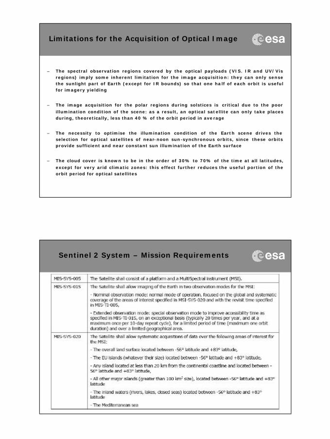
Limitations for the Acquisition of Optical Image
– The spectral observation regions covered by the optical payloads (VIS. IR and UV/Vis regions) imply some inherent limitation for the image acquisition: they can only sense the sunlight part of Earth (except for IR bounds) so that one half of each orbit is useful for imagery yielding
– The image acquisition for the polar regions during solstices is critical due to the poor
illumination condition of the scene: as a result, an optical satellite can only take places during, theoretically, less than 40 % of the orbit period in average
– The necessity to optimise the illumination condition of the Earth scene drives the selection for optical satellites of near-noon sun-synchronous orbits, since these orbits provide sufficient and near constant sun illumination of the Earth surface
– The cloud cover is known to be in the order of 30% to 70% of the time at all latitudes,
except for very arid climatic zones: this effect further reduces the useful portion of the orbit period for optical satellites
Sentinel 2 System – Mission Requirements

Sentinel 2 System – Application Requirements
Sentinel -2 – Overall Mission Constraints

Sentinel -2 Spectral Bands vs Spatial Resolution
Spectral bands versus spatial resolution
400 nm
600 nm
800 nm
1000 n m
1200 n m
1400 nm
1600 nm
1800 nm
2000 nm
2200 nm
2400 nm
10 m
20 m
60 m
VNIRSWIR
Visible
VIS NIR SWIR
B1
B2 B3 B4 B8
B5
B6
B7 B8a
B9 B10
B11 B12
VegetationRed-edge
Aerosols Water-vapour Cirrus
Snow / ice / cloud discrimination
Continuity with SPOT5 multispectral
Orbit Determination Process Altitude vs Repeat Cycle Length

Orbit Determination Process Trade off (with simulation tools)
300km
300km15°
15°
Definition of the Orbit
– Q=14+3/10 defines entirely the orbit. In fact:
– Q=143 orbits per 10 daysà 1 orbit is done in 6041.958 s
– `RE=6378 km, µ=398600 km3/s2, T=6042 s
– z = 794 km
– J2= 1.08263×10⁻³, e=0, a=RE+zand dO/dt= 1.991 10-7 rad/s
– Cos(i) = - 0.149143129 à i= 98°.557

Selecting the Local Time #1
– Based on the limitation in the SZA (75 degrees at maximum), it is possible to determine the more adequate LTAN or LTDN for proper observation over Europe. The results show that the LTAN/LTDN that produce a near-noon condition over Europe are the best options
– In order to avoid the sun glint effect, the LTDN of 10:30 and the LTAN of 13:30 are good candidates, as they exhibit the same illumination conditions.
– Avoiding morning haze suggests using a LT > 10:00
– Sun glint is a phenomenon that occurs when the sun reflects off the surface of the ocean at the same angle that a satellite sensor is viewing the surface
– A cloud coverage analysis with real cloud data over Europe from Meteosathas been performed, taking one full year of observations
– It has been verified with real cloud data that the best times for optical observations of Europe in terms of cloud coverage are the early times in the morning. In general, the earlier the node crossing time, the higher our chances to get a clear picture of the surface
Selecting the Local Time #2
– Simulation shows that the orbit with LTDN 10:30 present less cloud coverage than LTAN 13:30. Therefore the proposed time for the node was LTDN 10:30.

Sentinel -2 System description
• Filter based push broom imager (280KG, 1m3)
• Three mirrors silicon carbide telescope, with dichroicbeam splitter
• Focal plane arrays: Si CMOS VNIR detectors, HgCdTeSWIR detectors passively cooled (190K)
• Onboard wavelet compression (~1/3)
• Integrated video & compression electronics (state of the art wavelet compression)
• Radiometric resolution 12bits
• Radiometric accuracy < 5%
• Satellite mass: 1200KG
• Satellite power consumption: 1400W (1700W at Solar Array level, GaAs triple junction), 87Ah battery
• Hydrazine propulsion system (117Kg)
• TT&C using S band (64Kb/s up – 2018Kb/s down), with authenticated/encrypted commands
• X band mission data distribution (520 Mbits/sec)
• Mission data onboard storage: > 2.4 Tbits
• Optical Communication Payload
• Wheels, magnetometers, magnetorquers, star trackers, coarse sun and earth sensors, accurate Inertial Measurement Unit and GPS
Satellite MultiSpectral instrument
Sentinel -2 Data Delivery
– Data delivered to 4 core GS within 1-3 hours after acquisition.– X band data downlink with instrument data rate of 490 Mbit/s (after onboard wavelet
compression)– Laser Communication through geo terminal (can be operated simultaneously with
the X band subsystem). – 900 Gbyte per day (1000 CDs): cloud-free images will be further processed.
Core Ground Stations used for the simulation:
Kiruna, Svalbard, Maspalomas, Prince Albert

Sentinel -2 Services
General services: Global carbon, Crop monitoring, Spatial planning (vegetation, urban), Forest monitoring, Water services, Soil erosion, large scale natural or man made disasters, surveillance of infrastructures
Thematic services: Sustainable management of developing countries, Nature protection services, support to humanitarian aid, Food security
SAR in SSO – Simplified Orbit Selection #1
– SAR payloads work independently of the sun illumination conditions: this allows the satellite to be injected in orbits which are unfavourable for optical satellites
– Moreover, since images can be obtained during the night and in presence of heavy cloud cover, the SAR satellites can operate for a good percentage of the satellite orbit period, spacecraft bus resources permitting
– The SAR payload is required to operate in multiple modes. Trade off between geometric resolution vs swath width and geometric resolution vs radiometric resolution are required.

SAR in SSO – Simplified Orbit Selection #2
– High repeat cycle length permits to implement incidence angle diversity. In fact, the higher is the repeat cycle length (D) and the lower is the extension of the basic sub-interval (Si). allowing the SAR instrument to acquire the same target more times during the orbit cycle and with different incidence angles.
– The global accessibility is achieved if the instrument access at the equator is greater then the orbit basic sub-interval (the angular equatorial distance between trace patterns day by day), i.e.: Access Area > Si
This criterion is conservative as it guarantees the accessibility for two times during the whole orbit cycle
SAR in SSO – Simplified Orbit Selection #3
– …an orbit with a repeat cycle interval which exactly fits the required revisit period implies that a certain site would be viewed with the same incidence angle, preventing the exercise of the multiple incidence angle option
– Therefore, the preferred orbit would be a skipping orbit having a repeat cycle sufficiently small to provide an acceptable revisit time while warranting an effective repeat cycle sufficiently high to allow multiple incidence angle imagery
– Once the global coverage criterion is satisfied, the maximum revisit time is no greater than the repeat cycle interval.
– Within the set of orbits satisfying the global coverage criterion, this would suggest choice of the orbit with the shorter repeat cycle, but…
SAR System Design Considerations #1
– Requirements on Power and Signal-to-Noise ratio, Resolution, Incidence angle, Swath Width, Wavelength, Polarisation, Calibration Accuracy and SNR further constraint the design of the SAR System.
– Additional constraints are imposed by the available platform resources and mission design such as Payload Mass and Volume, Power, Ephemeris/Attitude Determination Accuracy, Attitude Control, Downlink Data rate etc
– Given the above inputs, one determines the System Specifications, such as System Gain (losses), rms error versus frequency, receiver noise figure, System Stability (gain/phase versus time and temperature) etc
– Final design is the result of an iterative procedure
SAR System Design Considerations #2
– Assume that the measurable range of target backscatter coefficient (s°) and the wavelength ? are specified by the users.
– Assume that Mass and Power Budgets are constrained by the launchvehicle:
– Maximum antenna area and the antenna gain G are limited by the mass
– Maximum Radiated Power is limited by the available DC Power
– Minimum Noise Temperature is determined by the Earth temperature (~300 °K) and the receiver noise figure
– Slant Range R is determined by the imaging geometry and the platform altitude
– If we consider the single pulse Radar Equation for distributed target to derive the SNR (which is a typical and fundamental design requirement), we realise that there are not many degree of freedom left…

SAR System Design Considerations #3
– Available parameters to enhance the SNR:
– Increase the Pulse Duration à Increase Average Power Consumption
– Decrease the antenna length while increasing the width to keep Gconstant à reduce the swath width and increase the average power consumption due to the higher PRF required
– Reduce system losses improving the antenna feed system or by inserting T/R modules into the feed to improve the system gain àincrease power consumption and costs
– Lowering the altitude produces a significant improvement of SNR àdecrease the swath width
( )
⋅⋅
⋅⋅
⋅
⋅⋅
⋅
⋅⋅⋅⋅
=a
p
nnop
t
LRc
BTkFRGP
SNRλ
ητσ
πλ
sin24
0
43
22
SAR System Design Considerations #4
– All the options to improve the SNR and therefore the quality of imagery requires power and resources of the platform
– User performance specifications, radar system parameters and platform resources are strongly interlaced
– There is no universal algorithm that can optimise the design across the wide range of applications: the priority ranking of the system performance parameters depends on the data utilisation and consequently on the users.
– Final design is usually a compromise between available resources and user needs: designers can also request a modification in the given requirements to match available programmatic constraints

Case Study: Sentinel-1 Performance Requirements
Mode Access Angle
Single Look Resolution
Swath Width Polarisation
Interferometric
Wide Swath
> 25 deg Range 5 m
Azimuth 20 m
> 250 km HH+HV or
VV+VH
Wave mode 23 degand
36.5 deg
Range 5 m
Azimuth 5 m
> 20 x 20 km
Vignettes at
100 km intervals
HH or VV
Strip Map 20-45 deg. Range 5 m
Azimuth 5 m
> 80 km HH+HV or
VV+VH
Extra Wide Swath > 20 deg. Range 20 m
Azimuth 40 m
> 400 km HH+HV or
VV+VH
For All Modes
Radiometric accuracy (3 s ) 1 dB
Noise Equivalent Sigma Zero -22 dB
Point Target Ambiguity Ratio -25 dB
Distributed Target Ambiguity Ratio -22 dB
Main modes
Sentinel-1 System
Space Segment
– A constellation of two satellites – Nominal lifetime in orbit of 7 years (consumables for 12) – Global coverage – Near-Polar Sun-Synchronous dusk-dawn orbit @ 693km.– Repeat Cycle 12 days, 175 orbit (14 + 7/12 orbit per day)– ~60 GByte/orbit, ~ 1 TByte/day– C-Band Synthetic Aperture Radar Payload– Equipped with an Optical Communication Terminal for GEO laser link
Ground Segment
– S-Band station (Kiruna proposed), with a back-up for S/C contingencies
– Downlink currently assumes three X-Band receiving stations– Alternative downlink via EDRS upon service availability

Instrument Accommodation on Spacecraft
SAR Antenna Subsystem (SAS), Aperture : 12.3 m x 0.84 m
14 Tiles each with 20 dual polarized resonant waveguide arrays =280 Dual Polarised T/R modules
SAR Electronic Subsystem (SES)
Sentinel-1 Satellite System Sizing and Performance
Satellite Features Performance Parameters
Overall Launch Mass 2298 kg (incl. 135 kg prop.)
Main Body Dimensions 3400 x 1340 x 1340 mm
Operational lifetime 7.25 years
Propellant lifetime 12 years
Operative autonomy 96 h
Attitude Profile Geo-Centric and Geodetic, 3 axes stabilized. Nominal Attitude: Right LookingContinuous steering in Yaw, Pitch and Roll
Attitude accuracy and knowledge Accuracy: 0.01° each axis. Knowledge: better than 0.003° each axis
Orbit Knowledge accuracy 10 m (3 sigma) each axis real-time processing. GPS data allow 5 cm in post-processing on ground.
Propulsion Mono-propellant, 6 (orbit) + 8 (attitude) thrusters
Power 5980W SAW generated Power (EOL). 240 Ah Li-Ion battery. @ 65V
TT&C S-Band, zenith/nadir antennas: 64 kbps U/L and 128/2048 kbps (switchable) D/L TLM Data
On-Bard Storage Capacity 1410 Gbit @ EOL
Data Downlink X-Band (8.025 – 8.400GHz) - 2 x 260Mbps (useful data rate) 8PSK, 4D-TCM
Satellite Reliability & Availability Reliability : 0.74 @ 7.25years. Availability :0.983

Summary of the Level 2 product Performance prediction
S1 Level-2 Product Resolution Performance Units
Subsidence Rate 5 x 5/20 m2 1.3/1.3 mm/year
Land Cover Classification (2
dB contrast )
30 x 30 m2 90/75 % correct classification
Forest Non-Forest
Classification
30 x 30 m2 98.6/75 % correct classification
Soil Moisture 100 x 100 m2 0.8/1.2 volume %
Flood Mapping 30 x 30 m2 93/79 % correct classification
Snow Cover Classification 30 x 30 m2 80/75 % correct classification
Ship Detection 5 x 20 m2 20/40 ship length (m)
Sea Surface Wind Speed 100 x 100 m2 0.4/0.8 m/s
Sea Surface Currents 5 Hz 30/30 cm/s
Sentinels 1-3: main sensor characteristics

Conclusion
–Thank you for your patience!!!!