misty cadra nova spectra nova whisper … misty gb cor.pdf · installation guide and user manual...
TRANSCRIPT

installation guide and user manualroom-sealed built-in gas-fireplace
40 010 52702 37
SILENCE
FEELING
WHISPER
SPECTRA NOVA
CADRA NOVA
MISTY
Saturnus 8 NL-8448 CC HeerenveenPostbus 219 NL-8440 AE HeerenveenT. +31(0)513 656500F. +31(0)513 656501
“Log Burner Technology”

1
CONTENTS
1. INTRODUCTION 2
2. SAFETY INSTRUCTIONS 3
3. INSTALLATION REQUIREMENTS 53.1 Builders opening and surround 53.2 Requirements outlet and exhaust 8
4. INSTALLATION-INSTRUCTIONS 174.1 Gas connection 174.2 Preparation of the appliance 174.3 Fitting the firebox 244.4 Placing of the wood set 26
5. INSTALLATION OF THE FLUE 275.1 Connection of the flue 275.2 Placing through existing chimney 285.3 Remote control 30
6. COMMISIONING 326.1 Check pilot ignition 326.2 Functional burner check 326.3 Functional balanced flue check 336.2 Check reference pressure 33
7. HANDING OVER 34
8. SERVICING 358.1 Routine annual servicing 35
USER GUIDE 45
9. SAFETY INSTRUCTIONS FOR THE USER 46
10. CONTROLING THE APPLIANCE 48
11. CLEANING AND SERVICE INSTRUCTIONS 54
12. DISPOSAL OF THE PACKAGING AND THE APPLIANCE 55
INDEX 1 LIST OF SPARE PARTS 40
INDEX 2 TECHNICAL DATA 41
UK/IRL

UK/IRL
2
UK/IRL
3
1. INTRODUCTION
Note: these instructions should be read carefully and retained forfuture reference. Please leave these instructions with the user.
This guide is concerning the following types of appliances:
Widescreen interior: Types Silence and FeelingRoundscreen interior: Type MistyMV100 interior: Type WhisperMV110 interior: Types Spectra Nova and Cadra Nova
Special features:
- Realistic flame and glow effect because of the "Log burner"technology.
- Room sealed appliance, inlet and outlet are led to the outsideusing a natural draught concentric pipe system (100 mm/150 mm)(no power fan required). No additional ventilation required.
- Air supply and flue-gases go to outside atmosphere through wall orroof. A maximum horizontal extension of 6 meters is possible.
- Remote Control option on all appliances.
- Meets the essential requirements of the European Gas ApplianceDirective (GAD) and carries the CE mark.
2. SAFETY AND GENERAL
INFORMATION
Before installation, ensure that the local distribution conditions(identification of the type of gas and pressure) and the adjustment ofthe appliance are compatible.
This gas appliance is factory set and shall not be adjusted by theinstaller.
This appliance does not contain any component manufactured fromasbestos or any asbestos related products.
The pilot and flame sensing device fitted to this fire is also a safetydevice. If for any reason any part of the pilot assembly is to bereplaced the entire assembly including the pilot burner, thermocouple,electrode and injector must be exchanged complete for a pilot assemblyfrom the original manufacturer only.
VentilationThis appliance is room-sealed and doesn't require purpose providedventilation.
2.1 General safety
It is the law in the UK that all gas appliances, are installed by acompetent person in accordance with the Gas Safety (Installation andUse) Regulations (as amended), the relevant British Standards forInstallation work, Building Regulations, Codes of Practice and themanufacturers instructions.The installation should also be carried out in accordance with thefollowing where relevant:
BS5871 Part1 BS5440 Parts 1 & 2 BS1251.
Building Regulations Document J (as applicable).

UK/IRL
5
UK/IRL
4
Building Regulations and Standards issued as relevant by theDepartment of the Environment or the Scottish DevelopmentDepartment.
In the Republic of Ireland installation should be carried out inaccordance with IS813, ICP3, IS327, Building Regulations, Codes ofPractice, the manufacturers instructions and any other rules in force.
Failure to comply with the above could leave the installer liable toprosecution and invalidate the appliance warranty.
Safety instructions for the user: see chapter 9.
3. INSTALLATION REQUIREMENTS
Note:Since the appliance is a source of heat, circulation of air occurs.Therefore it is of importance that you do not use the applianceshortly after a renovation of the home. Because of the naturalcirculation of air, moist and volatile components from paint, buildingmaterials, carpet etc. will be attracted. These components can settlethemselves down onto cold surfaces in the form of soot.
As on all heat producing appliances, soft furnishings such as blownvinyl wallpaper placed too near to the appliance may becomescorched or discoloured. This should be born in mind when installingthe appliance.
3.1 Builders opening and surround
The appliance can be installed in the following situations:
In a non-combustible fireplace or builders opening. This could be eitheran existing builders opening or a new made prefab builders opening.For the measurements, see figure 1 and index.
Although the appliance is tested for installation without a hearth, theappliance must not stand on combustible materials or carpets. If theappliance is placed on a combustible floor then a fibrelux or similarheatproof board of 12 mm thickness should be placed under it. Anyunder floor vents or openings within the builders opening should besealed off.
Do not place the lintel, surround or marble stone directly onto theappliance. If possible, apply a lintel made of cement or somethingsimilar.
Isolate the appliance with a ceramic blanket (25 mm). See also chapter 4: Installation instructions.Preferred choice for insulation is unbound insulation wool (at 1000 °C gives no smell).

L M
F
I
C B
AJ
E
D
G
K
H
Builders opening (mm) Feeling Silence Whisper Spectra Cadra MistyNova Nova
A Opening width* 960 960 780 780 680 710B Opening height* 649 649 705 698 798 890C Opening depth* 385 385 430 430 430 370
Shelf dimensions (combustible)
D Min. height shelf fromtop frame 350 350 350 350 350 350
E Depth shelf max. 150 150 150 150 150 150Dimensions (mm)
F Box width 880 880 750 750 650 698G Box depth 366 366 397 375 375 338H Box height 636 636 714 715 815 879I Frame width 1064 1064 815 794 694 740J Frame height 678 678 720 703 803 905K Frame thickness 47 20 16 30 30 144L Position flue
(behind frame) 255 255 257 235 235 196M Position flue (from the
back side box) 111 111 140 140 140 142
UK/IRL
7
UK/IRL
6
3.1 Builders opening and surround (continuing)
If the builders' opening is constructed out of non-combustiblecomposition board (Fibrelux) and you install the appliance without amantel then:
- Ventilate the space above the appliance (min. 1000 mm2 ).
- Always fit the DC convection set.
- The plaster of the outside has to be resistant to a hightemperature. Use therefore the plaster materials especially made forthis, to prevent discoloring (min. 100 °C temperature resistant).
If the appliance is to be fitted against a wall with combustiblecladding, the cladding must be removed from the area covered by thesurround.
The minimum height from the top surface of the fire to the undersideof any shelf made from wood or other combustible materials is asfollows:
- For a shelf up to 150 mm deep – Minimum height = 350 mm (fig. 1).
- If the shelf depth is greater than 150 mm add 50 mm to the upper-clearance height for every 25 mm increase in shelf depth.
- Side clearance = Minimum distance from the side of the fire frameto combustible material = 150 mm.
fig. 1
table 1
*the points A until C applies a tolerance from:– 0 mm and + 5 mm.

UK/IRL
9
UK/IRL
8
3.2 Flue requirements
The appliance is of the type C11/C31. The appliance will need to besupplied with the approved flue pipes and terminal, it is not possible tosupply your own.
The minimum effective height of the flue system must be 0.5 or 1 meter,depending on the appliance.
Terminal locations, through the wall as well as through the roof. Seefigure 3.
Flue routing; - a horizontal extension with elbows is allowed for a maximum of6 meters (depending on the type and situation).
- vertical max. 12 meters.
Determine on the base of the table 2 and 3, depending on the typeand terminal position, if the desired situation is possible.
To establish this you will need to calculate:
- The effective height (this is the real difference in height between theupper side of the appliance and the terminal).
- The total horizontal extension. This is the total horizontal flue lengthwhere:
• each elbow, which is in the horizontal area, counts for 2 meters.• each 45-degree bend, which is in the horizontal area, counts for
1 meter.• elbows and bends at the transition of horizontal to vertically are
not to be counted.• the wall mounted terminal counts for 1 meter.
Flue restrictor
If applicable, in the table is also stated the size of a flue restrictor.This restrictor needs to be fitted in the combustion chamber whenplacing the appliance ( see chapter 4.2). Normally the smallest fluerestrictor is fitted.
UK/IRL
0 1 2 3 4 5 60 X X X X X X X
X X X X X XX X X X X
X X X XX X X
X XX
1 30 0 0 0 0 0 0/X*2 30 30 0 0 0 0 03 45 45 30 0 0 0 04 45 45 30 0 0 0 05 50 50 45 45 30 0 06 50 50 45 45 30 0 07 60 60 60 50 50 458 60 60 60 60 509 65 65 60 6010 65 65 6511 65 6512 65
Horizontal extension
Effe
ctiv
e he
ight
X combinationnot allowed
0 remove flue restrictor
Number is size in mmof the flue restrictor
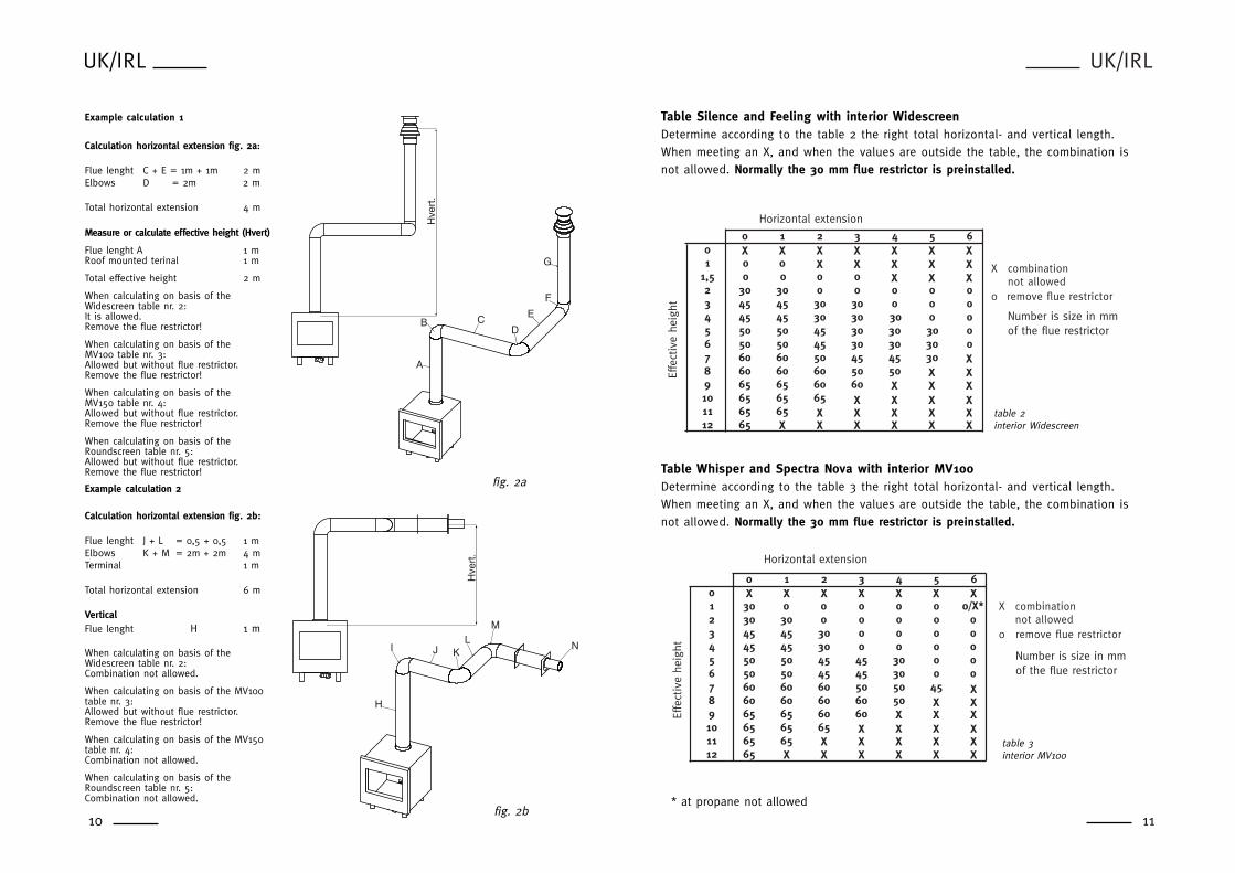
Table Silence and Feeling with interior WidescreenDetermine according to the table 2 the right total horizontal- and vertical length.When meeting an X, and when the values are outside the table, the combination isnot allowed. Normally the 30 mm flue restrictor is preinstalled.
Table Whisper and Spectra Nova with interior MV100Determine according to the table 3 the right total horizontal- and vertical length.When meeting an X, and when the values are outside the table, the combination isnot allowed. Normally the 30 mm flue restrictor is preinstalled.
0 1 2 3 4 5 60 X X X X X X X
X X X X X XX X X X X
X X X XX X X
X XX
X X X X XX X X
1 0 01,5 0 0 0 02 30 30 0 0 0 0 03 45 45 30 30 0 0 04 45 45 30 30 30 0 05 50 50 45 30 30 30 06 50 50 45 30 30 30 07 60 60 50 45 45 308 60 60 60 50 509 65 65 60 6010 65 65 6511 65 6512 65
X combinationnot allowed
0 remove flue restrictor
Horizontal extension
Effe
ctiv
e he
ight
Number is size in mmof the flue restrictor
table 2interior Widescreen
table 3interior MV100
UK/IRL
10
fig. 2aH
vert
.
N
ML
KJI
H
fig. 2b
Hve
rt.
A
F
G
E
DCB
Example calculation 1
Calculati0n horizontal extension fig. 2a:
Flue lenght C + E = 1m + 1m 2 mElbows D = 2m 2 m
Total horizontal extension 4 m
Measure or calculate effective height (Hvert)
Flue lenght A 1 mRoof mounted terinal 1 m
Total effective height 2 m
When calculating on basis of the Widescreen table nr. 2:It is allowed.Remove the flue restrictor!
When calculating on basis of the MV100 table nr. 3:Allowed but without flue restrictor.Remove the flue restrictor!
When calculating on basis of the MV150 table nr. 4:Allowed but without flue restrictor.Remove the flue restrictor!
When calculating on basis of the Roundscreen table nr. 5:Allowed but without flue restrictor.Remove the flue restrictor!
11* at propane not allowed
Example calculation 2
Calculati0n horizontal extension fig. 2b:
Flue lenght J + L = 0,5 + 0,5 1 mElbows K + M = 2m + 2m 4 mTerminal 1 m
Total horizontal extension 6 m
VerticalFlue lenght H 1 m
When calculating on basis of theWidescreen table nr. 2:Combination not allowed.
When calculating on basis of the MV100table nr. 3:Allowed but without flue restrictor.Remove the flue restrictor!
When calculating on basis of the MV150table nr. 4:Combination not allowed.
When calculating on basis of theRoundscreen table nr. 5:Combination not allowed.

UK/IRL
13
3.2 Flue requirements (continuing)
3.2.1 Terminal positionVerify if the required terminal position meets the local installationregulations regarding disturbance, good functioning and ventilation.(Also see: safety requirements).Note:The terminal must be located so that the outlet is not obstructed. Ifthe flue terminal is located within 2 meters of a footway, path orwhere people could come into contact with it then a suitableterminal guard must be fitted.
Terminals located close to shared walkways, footpaths etc. could besubject to legal constraints and this should be pointed out to thecustomer before installation. If in any doubt about flue locationadvice should be sought from local building control, or if appliance-related, from the manufacturer including wherever possible adimensioned sketch.
Avoid locating the terminal in close proximity to plastic materialssuch as gutters or other combustibles. If this is unavoidable then asuitable deflector should be made.
Some important requirements for a good functioning are:
The wall-mounted terminal has to be at a distance of at least0.5 meters off:- Corners of the building.- Below eaves.- Balcony's etc. unless the duct is dragged to the front side of the
overhanging part.
The roof mounted terminal has to be at a distance of at least0.5 meters of the sides of the roof, excluded the ridge.
UK/IRL
12
Table Cadra Nova with interior MV150Determine according to the table 4 the right total horizontal- and vertical length.When meeting an X, and when the values are outside the table, the combination is notallowed. Normally the 30 mm flue restrictor is preinstalled.
Misty with roundscreenDetermine according to the table 5 the right total horizontal- and vertical length.When meeting an X, and when the values are outside the table, the combination is notallowed. Normally the 30 mm flue restrictor is preinstalled.
0 1 2 3 4 5 60 X X X X X X X
X X X X X XX X X X X
X X X XX X X
X XX
X X X X X0 X X
0,5 X 01 X 30 0 0
0 0 01,5 40 30 0 02 40 30 0 0 0 0 03 40 40 30 0 0 0 04 50 40 40 30 0 0 05 50 50 40 40 30 30 06 50 50 50 40 40 30 07 60 50 50 40 40 408 60 60 50 50 509 60 60 60 5010 65 60 6011 65 6512 65
X combinationnot allowed
0 remove flue restrictor
Horizontal extension
Effe
ctiv
e he
ight
Number is size in mm of the flue restrictor
table 5 interior Roundscreen
0 1 2 3 4 5 60 X X X X X X X
X X X X X60 X X X X
50 X X X50 X X
40 X0
0,5 X 0 X X X X X1 30 0 0 0 0 X2 40 30 0 0 0 0 03 40 40 30 0 0 0 04 50 40 40 30 0 0 05 50 50 40 40 30 30 06 50 50 50 40 40 307 60 50 50 40 408 60 60 50 509 60 60 6010 65 60
6511 6565
Horizontal extension
Effe
ctiv
e he
ight
X combinationnot allowed
0 remove flue restrictor
Number is size in mm of the flue restrictor
X
12 XX X X X X
table 4 interior Cadra Nova

Table 6
UK/IRL
15
UK/IRL
14
Dimension Terminal position Balanced flue room sealed(kW input 7.5 kW expressed in net) Natural draught
A Direct below an opening, airbrick, 300 mmopening windows, etc.
B Above an opening, airbrick, 300 mmopening window ect.
C Horizontally to an opening, airbrick, 300 mmopening window etc.
D Below gutters, soil pipes or drain pipes 500 mmE Below eaves 500 mmF Below balconies or car port roof 600 mmG From a vertical drain pipe or soil pipe 300 mmH From an internal or external corner 600 mmI Above ground roof or balcony level 300 mmJ From a surface facing the terminal 600 mmK From a terminal facing the terminal 600 mmL From an opening in the carport (e.g. 1200 mm
window) into the dwellingM Vertically from a terminal on the same wall 1500 mmN Horizontally from a terminal on the same wall 300 mmP From a vertical structure on the roof 600 mmQ Above intersection with roof 500 mm
Flue terminal positions
fig. 3

UK/IRL
17
UK/IRL
16
4. INSTRUCTIONS FOR INSTALLATION
4.1 Gas connection
1. Installation pipes should be in accordance with BS 6891. Pipe workfrom the meter to the appliance must be of adequate size.
2. The complete installation including the meter must be tested forsoundness and purged as described in the above code.
3. A means of isolation must be provide in the supply to facilitateservicing.
4. The connection should be made in 8 mm copper or similar semiflexible tube. (max 1 meter). Ensure that the gas pipe does notinterfere with the removal or replacement of the burner tray of thecontrols.
5. The gas connection is nut and olive suitable for 8 mm pipe.
4.2 Preparing the appliances Widescreen and Whisper
1. Open the ashtray door by pushing on the right side for theSilence/Feeling and on the left side for the Whisper. Remove theframe by loosening the screws A behind the door (see fig. 5).Lift and pull forward when you take it away.
A
C
B
gas supply routes when fire is fitted in a deep surround
C = Through wall - Pipe must be sleeved and sealed to fire
A & B = Behind surround - Sleeve pipe through surround
inner wall
outer wall
cavity
surround
marble
Example of how terminal position is measured
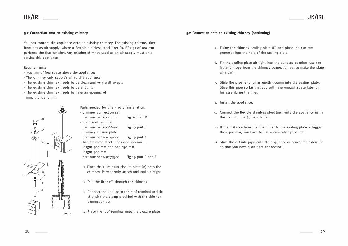
3.2.2 Using an existing chimney as air inlet You can connect the appliance onto an existing chimney. The existingchimney then functions as air supply, where a flexible stainless steelliner (to BS715) of 100 mm performs the flue function.
Requirements:- Any existing chimney used as an air supply must only service thisappliance.
- A chimney that has previously been used for solid fuel must be sweptbefore use.
- The existing chimney needs to be airtight.- The existing chimney needs to have an opening of min. 150 x 150 mm.
- The chimney needs to be intact and well looked after. - Use the adjustable roof-mounted-terminal especially made for this,and the chimney connection set.
- The minimum distance between two terminals should be at least450 mm.
fig. 4
fig. 5

UK/IRL
19
UK/IRL
18
4.2 Preparing the appliances Widescreen and Whisper (continuing)
4. Take the box with the log set out of the combustion chamber.
5. Place the right flue restrictor in the combustion chamber. Todetermine the right flue restrictor, see chapter 3.
CCC
CCC
C
C
C
C
�
fig. 8
fig. 9
4.2 Preparing the appliances Widescreen and Whisper (continuing)
2.
Remove the back panel by loosening the screws B (see fig. 6).
3. Remove the glass by removing the glass clamps C (see fig. 7) forinstance with a screwdriver. Careful when removing the glass! Weargloves! Before placing the glass back, be sure that there are nofingerprints on the glass, it is not possible to remove those printsafter you burn the appliance or a while (they will be burnt in).
AA
A
BB
BB
B
fig. 6
fig. 7

UK/IRL
21
4.3 Preparing the appliance Misty (continuing)
4. Take the box with the log set out of the combustion chamber.
5. Place the right flue restrictor in the combustion chamber. Todetermine the right flue restrictor, see chapter 3.
�
fig. 12
UK/IRL
20
4.3 Preparing the appliance Misty
1. Remove the door frame. Lift and pull forward (see fig. 10).
2. Open the ashtray door by pulling down (bottom handle).
3. To open the door, remove the screws C (see fig. 11). The dooropening is limited; if you need more space then remove the door (liftand pull forward). Be sure that there are no fingerprints on the glass.It is not possible to remove those prints after you burn the appliancefor a while (they are burnt in).
fig. 10
CC
CC
fig. 11

UK/IRL
23
UK/IRL
22
4.4 Preparing the appliances Spectra Nova/Cadra Nova (continuing)
4. Take the box with the log set out of the combustion chamber.
5. Place the right flue restrictor in the combustion chamber. Todetermine the right flue restrictor, see chapter 3.
�
fig. 15
4.4 Preparing the appliances Spectra Nova/Cadra Nova
1. To open the door, remove the screws A (see fig. 13). Open andremove the door; lift and pull forward. Be sure that there are nofingerprints on the glass. It is not possible to remove those printsafter you burn the appliance for a while (they are burnt in).
2. Remove the back panel by loosening the 4 screws B (see fig. 14).
fig. 13
fig. 14

UK/IRL
25
UK/IRL
24
4.5 Fitting the firebox (continuing)
8. Spread, the bags of embers (imitation ashes) provide with theappliance over the burner tray. Attention! No embers on the grid end between the logs and theburner tray.
9. Before placing the glass; check the glass sealing rope is in goodcondition and makes an effective seal. Be sure that there are nofingerprints on the glass. It is not possible to remove those printsafter you burn the appliance for a while (they are burnt in).
- Widescreen and Whisper; Place the glass in front of the applianceand fix it with the glass clamps. Replace the frame.
- Misty, Cadra Nova and Spectra Nova: Place the door and fix it. Check on visual leakages around thedoor sealing.
10. Misty and widescreen: Fix the back and top or door frame (the backframe first).
ceramic blanket
ceramic�blanket
ceramic�blanket
ceramic�blanket
ceramic �blanket
�
4.5 Fitting the firebox
Points of attention for placement:- If possible, first locate the appliance before assembling the flue.- If this is not possible then always use an extendible pipe beforeconnection onto the appliance.
1. Position the firebox in the fireplace opening. You can adjust theheight with the 4 adjustable feet.
2 Make the gas connection according to the instructions (also see gasconnection, chapter 4.1).
3. Assemble the flue system onto the firebox (see chapter 5).
4. Check if applicable that the safety hatch seals the combustionchamber properly.
5. If necessary, place the DC convection system (also consult theinstruction belonging to the DC construction set).
6. Isolate the firebox with a ceramic blanket (25 mm). Preferred choicefor insulation is unbound insulation wool (at 1000 °C gives nosmell).
7. Place the log set (see placing log set, chapter 4.4).
safety hatch
fig. 16
fig. 17

UK/IRL
27
UK/IRLUK/IRL
5. INSTALLATION OF THE FLUE
5.1 Connections with use of concentric duct material
- Build the system starting from the appliance on.
- Make a hole of ø 153 mm for the wall or roof mounted terminal.
- Make sure you place the pipes in the right direction, the narrowend towards the appliance.
- Make sure the pipes are fixed sufficiently, a wall clamp every 2m, sothe weight of the pipes is not resting onto the appliance.
- The outside of the pipe can become hot (140 degrees). Stay 50 mmaway from wall surface or sealing. Make sure to provide sufficientlyheat resistant isolation when going through the wall or roof.
- Because of expansion or cooling down the concentric pipes can turnloose. It is recommended to fix the spring clip with a self tappingscrew at inaccessible places.
- To get the exact measure flue length you can use cut down-concentric pipe, wall mounted terminal or roof mounted terminal. Toobtain a smoke sealed connection, the inner pipe must be 20 mmlonger then the outside pipe.
- The horizontal pipes need to rise away from the appliance at a rateof 3 degrees per metre.
UK/IRL
26
4.6 Placing the log set
Never place extra elements of any kind into the combustion chamber.To guarantee good combustion, the log set may only be installed inthe way specified by Faber International. Any other arrangement canlead to soot on logs or window. Do not use the fire with broken ormissing logs.
4.6.1 Placing the log set Widescreen, Whisper, Spectra Nova, Misty and Cadra Nova
On the bottom of the logs is a identification:
• L location on the left side resting on the rear log.• R location on the right side resting on the rear log.• 1 dimple first log left placed over the burner and resting on the
burner tray.• 2 dimples placed in the middle over he burner and resting on the
burner tray.• 3 dimples the right side log placed over the burner and resting on the
burner tray.
Attention! Beware that there are no embers between the logs and theburner tray.
fig. 18
fig. 19
UK/IRL
29
UK/IRL
28
UK/IRLUK/IRL
5.2 Connection onto an existing chimney (continuing)
5. Fixing the chimney sealing plate (D) and place the 150 mmgrommet into the hole of the sealing plate.
6. Fix the sealing plate air tight into the builders opening (use theisolation rope from the chimney connection set to make the plateair tight).
7. Slide the pipe (E) 150mm length 500mm into the sealing plate.Slide this pipe so far that you will have enough space later onfor assembling the liner.
8. Install the appliance.
9. Connect the flexible stainless steel liner onto the appliance usingthe 100mm pipe (F) as adapter.
10. If the distance from the flue outlet to the sealing plate is biggerthen 300 mm, you have to use a concentric pipe first.
11. Slide the outside pipe onto the appliance or concentric extensionso that you have a air tight connection.
UK/IRLUK/IRL
5.2 Connection onto an existing chimney
You can connect the appliance onto an existing chimney. The existing chimney thenfunctions as air supply, where a flexible stainless steel liner (to BS715) of 100 mmperforms the flue function. Any existing chimney used as an air supply must onlyservice this appliance.
Requirements:- 300 mm of free space above the appliance;- The chimney only supply’s air to this appliance; - The existing chimney needs to be clean and very well swept;- The existing chimney needs to be airtight;- The existing chimney needs to have an opening of
min. 150 x 150 mm.
Parts needed for this kind of installation:- Chimney connection set
part number A9225000 Fig 20 part D- Short roof terminal
part number A9266100 Fig 19 part B- Chimney closure plate
part number A 9240000 Fig 19 part A- Two stainless steel tubes one 100 mm -
length 500 mm and one 150 mm - length 500 mmpart number A 9273900 Fig 19 part E and F
1. Place the aluminium closure plate (A) onto thechimney. Permanently attach and make airtight.
2. Pull the liner (C) through the chimney.
3. Connect the liner onto the roof terminal and fixthis with the clamp provided with the chimneyconnection set.
4. Place the roof terminal onto the closure plate.
F
E
D
C
B
A
fig. 20

UK/IRL
31
UK/IRL
30
UK/IRLUK/IRL
3. Connect the wires to the gas valve (see fig. 22).
4. Check that there are batteries in the transmitter. See "Replacing batteries", see chapter 10.4.4.
5. Set the on/off switch on the receiver to "on".
Setting the right transmission code The receiver has to learn the code from the transmitter, which is alreadydone at the factory. However the code disappears if the receiver isdisconnected from the mains for a longer period.
1. Push the "mod" button on the receiver and hold it for 3 seconds.
2. The green control lamp will light up and stay on. Repeat this stepif it doesn't.
3. Push a button on the remote control. The control lamp on thereceiver should now go out.
4. Again push a button on the remote control. The lamp startsflashing and will switch off eventually.
5. The receiver now recognizes the remote control. The remotecontrol now functions.
6. Check if you can hear a sound and the motor runs when youpush a button on the remote control.
fig. 22
UK/IRLUK/IRL
5.3 Remote control (if applicable)
The remote control is only meant to regulate the flames, it functionsonly when the pilot burner is ignited. It is therefore not possible toignited the appliance with the remote control or to shut-off the pilot-flame.
The radio-frequency remote control is intended for fireplaces installedin a domestic setting in all EU countries except Austria, Denmark,Finland and Greece.
Features:- Manual control will always remain possible.- The remote control is a radio frequency type and has been approvedinternationally.
- The remote control generates a unique safety code every time youactivate the transmitter, its similar to those used in a car.
- The remote control is easy to install retrospectively.
5.3.1 Installation remote control 1. Connect the mains adapter to the receiver box. The adapter is set
to the correct voltage in the factory 4.5V.
2. Slide the receiver box into the holder.
fig. 21

UK/IRL
33
UK/IRL
32
UK/IRLUK/IRL
6.3 Functional balanced flue check
1. Set the appliance on max. input.2. Verify the flame picture, this means no flames against the
window, the flame have to come besides the logs, if not checkthe log layout.
3. Check if the flames are yellow after 10 minutes of operation. Ifyou still have a blue flame or the appliance goes out check: - If the flue pipes are fitted correctly (no leakage).- If the wall mounted terminal is placed with the correct side up.- If the correct flue restrictor is installed.
6.4 Check reference pressure
The appliance is preset to give the correct heat input.No further adjustment is necessary. Fit a pressure gauge at the testpoint D to check the burner pressure.
The pressure should be checked with the appliance alight and at maxinput.The setting pressure should be as shown at the technical datapage 41.
After checking the pressure, turn off the appliance. Remove thepressure gauge and close the sealing screw. Re-light the appliance.Turn to max. input and test around the test point D for gassoundness using a suitable leak detection fluid.
CDD C ABB A
fig. 24
UK/IRLUK/IRL
6. COMMISSIONING (functional checks)
6.1. Check pilot ignition
1. Push in and turn the control knob (A) from { anticlockwise to thesetting (small flame). You will hear a tick meaning there isignition. Hold the knob in and wait for a few seconds while the airis purged.
2. Bring the knob back in the start position and turn the knob severaltimes to the position. Check that the pilot has lit.
3. Continue to hold in the control knob for a further ten seconds toensure that the pilot flame is stable.
4. Release the knob. The pilot should remain alight.
6.2 Functional burner check
1. Turn knob (B) to max. clockwise.2. Turn the knob (A) more anticlockwise to the position (large
flame). Now it is possible to light the main burner.3. Turn knob B anticlockwise to max. The main burner should light.
Check for gas soundness at all joints with leak detection floud!4. Check the ignition of the main burner on low and high setting.5. Turn knob B clockwise till {. The main burner is off.6. Turn the knob A to {. The pilot should go out.
A B
fig. 23

UK/IRL
35
UK/IRL
34
8. SERVICING
To ensure safe, efficient operation of the appliance, it is necessary tocarry out routine servicing at regular intervals.
It is recommended, that the fire is inspected/serviced by a competentperson at least once a year.
Important Turn off the gas supply before commencing any servicing. Alwaystest for gas soundness after refitting the appliance.
8.1 Routine annual servicing
1. Clean (if necessary):- the pilot system;- the burner;- the combustion chamber;- the glass.
2. Check the log lay and replace the embers (if applicable).3. Do the functional test as described at page 34.4. Check the flue system and terminal on damage and soundness
(visual inspection).
UK/IRLUK/IRL
7. HANDING OVER
(final check and customer briefing)
7.1 Instruct the customer on the full operation of the appliance.
7.2.1 Advise the customer how to clean the appliance including theglass.
7.2.2 Instruct the customer on the operation of the remote control,including replacement of batteries and how to set the righttransmissions code.
7.2.3 Hand over these instructions including the user guide to theconsumer.
7.2.4 Recommend that the appliance should be serviced by acompetent person at least once a year.
UK/IRL
37
UK/IRL
36
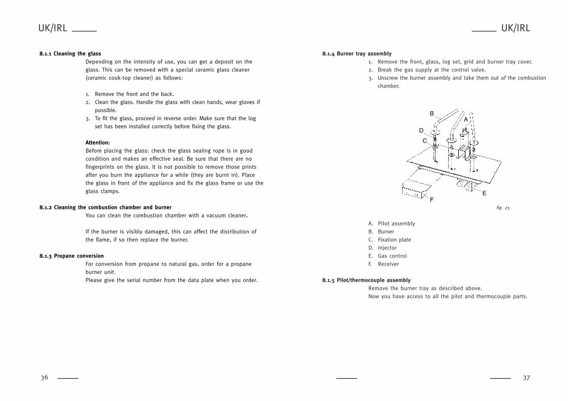
8.1.4 Burner tray assembly1. Remove the front, glass, log set, grid and burner tray cover.2. Break the gas supply at the control valve.3. Unscrew the burner assembly and take them out of the combustion
chamber.
A. Pilot assembly B. BurnerC. Fixation plate D. InjectorE. Gas controlF. Receiver
8.1.5 Pilot/thermocouple assemblyRemove the burner tray as described above. Now you have access to all the pilot and thermocouple parts.
fig. 25
AB
C
D
EF
8.1.1 Cleaning the glassDepending on the intensity of use, you can get a deposit on theglass. This can be removed with a special ceramic glass cleaner(ceramic cook-top cleaner) as follows:
1. Remove the front and the back.2. Clean the glass. Handle the glass with clean hands, wear gloves if
possible.3. To fit the glass, proceed in reverse order. Make sure that the log
set has been installed correctly before fixing the glass.
Attention:Before placing the glass: check the glass sealing rope is in goodcondition and makes an effective seal. Be sure that there are nofingerprints on the glass. It is not possible to remove those printsafter you burn the appliance for a while (they are burnt in). Placethe glass in front of the appliance and fix the glass frame or use theglass clamps.
8.1.2 Cleaning the combustion chamber and burnerYou can clean the combustion chamber with a vacuum cleaner.
If the burner is visibly damaged, this can affect the distribution ofthe flame, if so then replace the burner.
8.1.3 Propane conversionFor conversion from propane to natural gas, order for a propaneburner unit.Please give the serial number from the data plate when you order.

UK/IRL
39
UK/IRL
38
UK/IRLUK/IRL
8.1.7 Combustion testA BS7967 combustion analysis check should be carried out using ananalyser to BS7927 positioned in the flue outlet.
A Ratio of CO/CO2 should be less than 0.01 within 30 minutes.(100ppm CO per 1% CO2).
A reading of CO in the room centre should give a rise of less than9ppm over ambient, peak reading.
8.1.6 Gas control block
A GovernorB Adjusting screw pilot flameC Inlet pressure test pointD Burner pressure test point
CDD C
AB
B A
fig. 26

Whisper Feeling Silence Misty Spectra CadraNova Nova
Description Company Company Company Company Company Company part part part part part part
Surround antracite A9271453 A9270053 A9267753 AA9272853 A9274149 A9274249
Glass 04508200 04508300 04508300 04509000 4509500 04509300
Glass below x x x x 04509600 04509400
Burner NG 20521808 20521808 20521808 20521808 20521808 20900166
Burner propane 20521835 20521835 20521835 20521835 20521835 20900167
Log set 20773200 20774500 20772500 20786130 20773700 20773700
Spark wire 06017300 06017300 06017300 06017300 06017300 06017300
Receiver 20604000 20604000 20604000 20604000 20604000 20604000
Remote control 20603900 20603900 20603900 20603900 20603900 20603900
Adapter 20900142 20900142 20900142 20900142 20900142 20900142
Gas control 37003089 37003089 37003089 37003089 37003089 37003089
Motor (remote control) 37003086 37003086 37003086 37003086 37003086 37003086
Pilot burner assemb. NG 20900145 20900145 20900145 20900145 20900145 20900145
Pilot burner assemb.
propane 20900154 20900154 20900154 20900154 20900154 20900154
Thermocouple 37002033 37002033 37002033 37002033 37002033 37002033
Spark electrode 06006600 06006600 06006600 06006600 06006600 06006600
Embers 20900019 20900019 20900019 20900019 20900019 20900019
Heat resisting paint
spray for comb. chamb. 09000008 09000008 09000008 09000008 09000008 09000008
Set of glass clips 20900008 20900008 20900008 x x x
Touch Latch assembly 28103900 28103900 28103900 x x x
Country UK/IRL UK/IRL
Category II2H3+
II2H3+
Model type C11 0f C31 C11 0f C31
Heat input Hi kW 7,5 7,2
Efficiency class 2 2
NOX class 4 4
Type of gas G20 G30
Inlet pressure mbar 20 30 / 37
Gas rate 15 °C / 1013 mbar m3/h 740 231
kg/h 540 g
Reference burner pressure mbar 17 22
Injector size mm 3x 1,45 3x 1,00
1x 1,30
Reduced input restrictor mm 1,8 1,1
Pilot assembly
Type SIT 160 SIT 160
Code Nr 51 Nr 30
Flue system
MV size 100-150 100-150
Preinstalled flue restrictor mm 30 30
Gas control GV36 with GV36 without
pressure reg. pressure reg.
Remote control
Adapter V 4,5
Batteries remote control 2x LR03 1,5 V Alkaline
Gas connection mm 8 mm nut 18 mm nut
and olive. and olive
Dimensions: see table 1
UK/IRL
41
UK/IRL
40
8.3 TECHNICAL DATA
Widescreen Silence en Feeling C11/C31
8.2 LIST OF SPARE PARTS

Country UK/IRL UK/IRL
Category II2H3+
II2H3+
Model type C11 0f C31 C11 0f C31
Heat input Hi kW 7.5 7.5
Efficiency class 2 2
NOX class 4 4
Type of gas G20 G30
Inlet pressure mbar 20 30/37
Gas rate 15 °C / 1013 mbar m3/h 800 231
kg/h 540 g
Reference burner pressure mbar 13 25
Injector size mm 3x 1.50 3x 0.90
Reduced input restrictor mm 1.8 1.1
Pilot assembly
Type SIT 160 SIT 160
Code Nr 51 Nr 30
Flue system
MV size 100-150 100-150
Preinstalled flue restrictor mm 30 30
Gas control GV36 with GV36 without
pressure reg. pressure reg
Remote control
Voltage adapter V 4,5
Batteries 2x LR03 1,5 V Alkaline
Gas connection mm 8 mm nut 8 mm nut
and olive and olive
Weight incl. packing material kg 75 75
Dimensions: see table 1
Country UK/IRL UK/IRL
Category II2H3+
II2H3+
Model type C11 0f C31 C11 0f C31
Heat input Hi kW 7,5 7,5
Efficiency class 2 2
NOX class 4 4
Type of gas G20 G30
Inlet pressure mbar 20 30/37
Gas rate 15 °C / 1013 mba m3/h 790 231
kg/h 540 g
Reference burner pressure mbar 17 22
Injector size mm 2x 1,40 3x 1,00
1x 1,30
Reduced input restrictor mm 1,8 1,1
Pilot assembly
Type SIT 160 SIT 160
Code Nr 51 Nr 30
Flue system
MV size 100-150 100-150
Preinstalled flue restrictor mm 30 30
Gas control GV36 with GV36 without
pressure reg. pressure reg.
Remote control
Voltage adapter V 4,5
Batteries 2x LR03 1,5 V Alkaline
Gas connection mm 8 mm nut 8 mm nut
and olive and olive
Weight incl packing material kg 75 75
Dimensions: see table 1
UK/IRL
43
UK/IRL
42
8.3 TECHNICAL DATA
MV150 Cadra Nova
8.3 TECHNICAL DATA
MV100 Whisper and Spectra Nova

UK/IRL
45
UK/IRL
44
UK/IRLUK/IRLUK/IRL
USER GUIDE
8.3 TECHNICAL DATA
Roundscreen Misty
Country UK/IRL UK/IRL
Category II2H3+
II2H3+
Model type C11 0f C31 C11 0f C31
Heat input Hi kW 8,5 8,5
Efficiency class 2 2
NOX class 4 4
Type of gas G20 G30
Inlet pressure mbar 20 30 / 37
Gas rate 15 °C / 1013 mbar m3/h 900 231
kg/h 540 g
Reference burner pressure mbar 16 25
Injector size mm 3x 1,50 3x 0,95
Reduced input restrictor mm 1,8 1,1
Pilot assembly
Type SIT 160 SIT 160
Code Nr 51 Nr 30
Flue system
MV size 100-150 100-150
Preinstalled flue restrictor mm 30 30
Gas control GV36 with GV36 without
pressure reg. pressure reg.
Remote control
Voltage adapter V 4,5
Batteries 2x LR03 1,5 V Alkaline
Gas connection mm 8 mm nut 8 mm nut
and olive and olive
Dimensions: see table 1

UK/IRL
47
UK/IRL
46
IMPORTANT A suitable Fireguard conforming to BS6539 and BS6778 should be usedwith this appliance to protect children, the elderly or infirm. Careshould also be taken with pets.
In your own interest and that of safety, all gas appliances must beinstalled by competent persons. Installation must be in accordance withNational Regulations. CORGI registered installers are required to work torecognised standards.
Note:Since the appliance is a source of heat, circulation of air occurs.Therefore it is of importance that you do not use the appliance shortlyafter a renovation of the home. Because of the natural circulation of air,moist and volatile components from paint, building materials, carpet etc.will be attracted. These components can settle themselves down ontocold surfaces in the form of soot. As on all heat producing appliances,soft furnishings such as blown vinyl wallpaper placed too near to theappliance may become scorched or discoloured. This should be born inmind when installing the appliance.
9. SAFETY INSTRUCTIONS FOR THE
USER
9.1 General safety instructions
If a gas leak is found or suspected, turn off the gas supply at themeter and contact your installer or gas emergency service.
These instructions should be read carefully and retained for futurereference.
Do not use the fire with a broken or damaged glass.
The fire has a safety device which turns off the gas supply if there is abuild up from flue gasses in the combustion room or a temporary gascut-off. Wait at least 5 minutes before turning the appliance on again.Contact a qualified installer when the appliance goes off regularly.
The appliance has been designed for heating purposes. This means thatall surfaces, including the glass, can become very warm (over100 degrees). An exception to this is the lower side of the door and thecontrol buttons.
Due to the newness of materials, they may give off a slight smell for aperiod after initial lighting. This is normal, odours will disperse after afew hours use.
Do not place curtains, clothing, laundry, furniture or other flammablematerials nearby the appliance. The required minimum distance is 100 cm.
Switch off the receiver of the remote control if you don’t use the fire fora long time. Do not let children use the remote control withoutsupervision.

UK/IRL
49
UK/IRL
48
Knob AThe { is the OFF position preventing any gas from passing through thecontrol valve to either the pilot burner or to the main burner. By pressingthe knob in it is possible to turn it anticlockwise. The first function is toturn on the gas to the pilot- this occurs just before reaching the|position (if the fire has not been lit for some time it may be necessaryto hold the knob in this position for some seconds to clear the air fromthe pipe and allow gas to reach the pilot burner). Once gas is availableat the pilot, continued rotation anti-clockwise will cause the piezo igniterto spark. This is accompanied by a click at the valve and should result inthe pilot burner igniting. Once the pilot is lit, the control knob should beheld pressed in for 10 seconds. In this time the pilot flame will haveheated the flame supervision thermocouple sufficiently to operate a hold-on magnet within the valve. Now turn the control knob A to the
position. This allows gas to enter control knob B.
Knob BThe { is the OFF position preventing gas entering the main burner ifthe pilot is lit. The knob should be turned slowly anticlockwise. Thisallows gas to enter the burner and be ignited by the pilot flame. Onceignition has taken place, the fire may be set to any level between min.and max. by adjusting the control knob B.
10.2 To light
1. Push in and turn the control knob (A) from { anticlockwise tothe setting (small flame). You will hear a ignition click. Checkthat the pilot is lit (if not repeat).
2. Continue to hold in the control knob for a further ten seconds toensure that the pilot flame is stable.
3. Release the knob. The pilot should remain alight.
4. Turn the control knob A to the position.
5. Turn knob B slowly anticlockwise, the fire should then ignite.
6. Adjust flames to the required level.
10. CONTROLLING THE APPLIANCE
10.1 Lighting the fire
If the main burner or pilot light are extinguished for any reason, donot attempt to relight the pilot within 5 minutes. Contact a qualifiedinstaller when the appliance goes off regularly.
The control valve is behind the ashtray door.
Silence /Feeling /WhisperOpen the ashtray door by pushing on the right side for theSilence/Feeling and on the left side for the Whisper.
MistyOpen the ashtray door by pulling down (bottom handle with gasdamper).
Cadra Nova and Spectra Nova Open by pushing the lip located on the right side in the gap betweenthe ashtray door and the frame (door flaps open).
With control button A you can light the pilot. With the control buttonB you can adjust the height of the flames (see fig. 27).
fig. 27 control unit
A B

UK/IRL
51
UK/IRL
50
10.4.1 To light1. Push in and turn the control knob (A) from { anticlockwise to
the setting (small flame). You will hear a ignition click. Checkthat the pilot is lit (if not repeat).
2. Continue to hold in the control knob for a further ten seconds toensure that the pilot flame is stable.
3. Release the knob. The pilot should remain alight.
4. Turn the control knob A to the position.
5. Set the on/off switch on the receiver to "on”.
low flame
high flame
6. Use (high) and (low) to achieve the desired heating andflame effect.
7. You will hear a beep every time the receiver recognises a goodsignal. (If not, so see 10.4.3, setting the right transmission code).
8. When the fire is not be used for a prolonged period, turn off thepilot (see 10.4.2).
10.4.2 To extinguish1. Push (low) till the burner goes out and you can hear the motor
clicking.
2. To enable the remote control turn knob A to the position.
3. To extinguish the pilot turn control knob A to position {, althoughit is in order to leave the pilot permanently lit.
fig. 28
remote control
10.3 To extinguish
1. For the main burner turn the control knob B clockwise to position {.
2. To disable knob B turn knob A to the position.
3. To extinguish the pilot turn control knob A to position { , although it is in order lo leave the pilot permanently lit.
10.3.1 When the pilot extinguishesWarning! When the pilot extinguishes, for whatever reason, you shouldwait at least 5 minutes before trying to turn it on again.
Possible causes of pilot extinguish are:- Operating error.- Interference of the safety device.- Failure in the pilot flame system.
Contact a qualified installer when the appliance goes off regularly.
10.4 Remote control version
The remote control is only meant to regulate the flames from off tillmax., it functions only when the pilot burner is ignited and knob A in
(big flame) position. It is therefore not possible to ignite the pilotflame with the remote control or to extinguish the pilot flame. Theradio-frequency remote control is intended for fireplaces installed in adomestic setting in all EU countries except Austria, Denmark, Finland,and Greece.
Features:- Manual control will always remain possible.- The remote control is a radio frequency type and had been approvedinternationally.
- The remote control generates a unique safety code every time youactivate the transmitter, its similar to those used in a car.
- The remote control is easy to install retrospectively.

UK/IRL
53
UK/IRL
52
10.4.3 Setting the right transmission codehe receiver has to learn the code from the transmitter, which is alreadydone at the factory. However the code disappears if the receiver isdisconnected from the mains for a longer period,
1. Set the on/off switch on the receiver to "on".
2. Push the "mod" button on the receiver and hold it for 3 seconds.
3. The green control lamp will light up and stay on. Repeat this stepif it doesn't.
4. Push a button on the remote control. The control lamp on thereceiver should now go out.
5. Again push a button on the remote control. The lamp startsflashing and will switch off eventually.
6. The receiver now recognizes the remote control. The remotecontrol now functions.
7. Check if you can hear a sound and the motor runs when youpush a button on the remote control.
10.4.4 Changing the batteries There is no risk of electric shock as the low voltage supply is similarto that used in torches. Always turn off the appliance before changingbatteries.
Remote control
1. Remove the cover on the back of the remote control.
2. Carefully remove the battery clip along the side. Pay attention notto pull the wires.
3. If necessary, remove the old batteries and place the new ones:2 x LR03 Alkaline long life 1.5 V.
4. Click the battery clip into the remote control and close the cover.
5. It might be possible that you have to set the transmission codeafter changing the batteries (see 10.4.3).
NoteBatteries are chemical waste and should be disposed in accordancewith local regulations.
+
AA
A
+A
AA
fig. 29
changing batteries

UK/IRL
55
UK/IRL
54
UK/IRLUK/IRLUK/IRLUK/IRL
12. DISPOSAL OF THE PACKAGING
AND THE APPLIANCE
The appliance packaging is recyclable. The packaging could includethe following materials:- cardboard;- CFC-free foam (soft);- wood;- plastic;- paper.
These materials should be disposed responsibly and in conformitywith government regulations.
Batteries are considered chemical waste. The batteries should bedisposed of responsibly and in conformity with governmentregulations. Remove the batteries before disposing of the remotecontrol.
Information on how to responsibly dispose of discarded appliancescan be obtained from the local authorities.
11. CLEANING AND SERVICE
INSTRUCTIONS
Important: Turn off the fire and allow it to cool down beforecommencing cleaning.
It is recommended that the fire is inspected/serviced, by a competentperson at least once a year.
To maintain the finish on the trim wipe with soft damp cloth only. Donot use abrasive cleaners, polish or solvents as these can damagethe surface finish.