mit 2.810 manufacturing processes and systems homework 4...
TRANSCRIPT
MIT2.810Fall2016 Homework4Solutions
MIT2.810ManufacturingProcessesandSystemsHomework4Solutions
InjectionMoldingandHeatTransfer
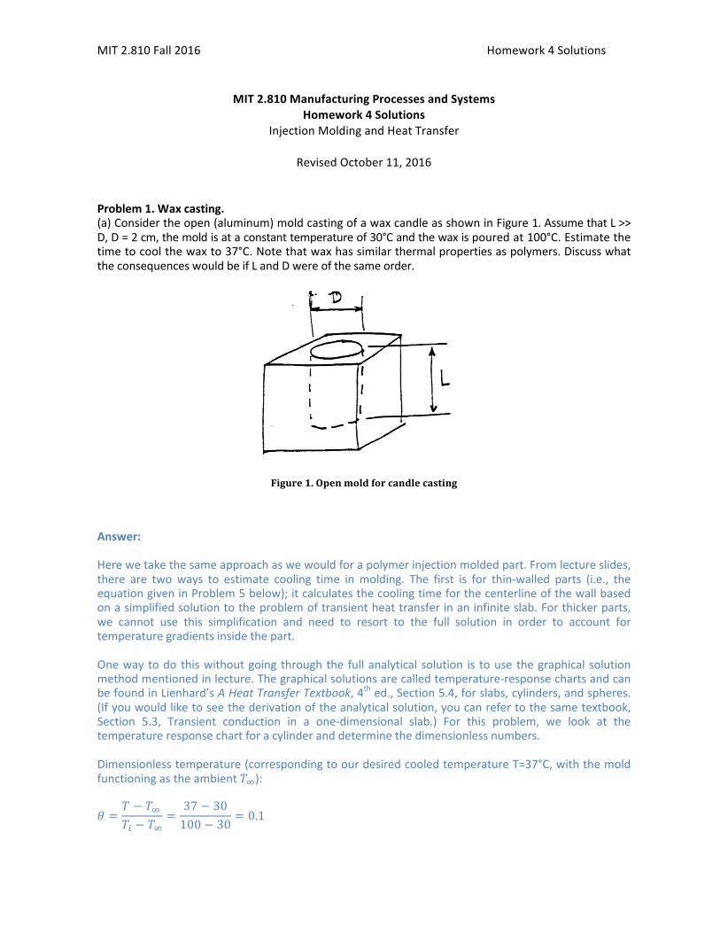
RevisedOctober11,2016Problem1.Waxcasting.(a)Considertheopen(aluminum)moldcastingofawaxcandleasshowninFigure1.AssumethatL>>D,D=2cm,themoldisataconstanttemperatureof30°Candthewaxispouredat100°C.Estimatethetimetocoolthewaxto37°C.Notethatwaxhassimilarthermalpropertiesaspolymers.DiscusswhattheconsequenceswouldbeifLandDwereofthesameorder.
Figure1.Openmoldforcandlecasting
Answer:Herewetakethesameapproachaswewouldforapolymerinjectionmoldedpart.Fromlectureslides,there are two ways to estimate cooling time inmolding. The first is for thin-walled parts (i.e., theequationgiveninProblem5below);itcalculatesthecoolingtimeforthecenterlineofthewallbasedonasimplifiedsolutiontotheproblemoftransientheattransferinaninfiniteslab.Forthickerparts,we cannot use this simplification and need to resort to the full solution in order to account fortemperaturegradientsinsidethepart.Onewaytodo thiswithoutgoing throughthe fullanalytical solution is touse thegraphical solutionmethodmentionedinlecture.Thegraphicalsolutionsarecalledtemperature-responsechartsandcanbefoundinLienhard’sAHeatTransferTextbook,4thed.,Section5.4,forslabs,cylinders,andspheres.(Ifyouwouldliketoseethederivationoftheanalyticalsolution,youcanrefertothesametextbook,Section 5.3, Transient conduction in a one-dimensional slab.) For this problem, we look at thetemperatureresponsechartforacylinderanddeterminethedimensionlessnumbers.Dimensionlesstemperature(correspondingtoourdesiredcooledtemperatureT=37°C,withthemoldfunctioningastheambient𝑇!):
𝜃 =𝑇 − 𝑇!
𝑇! − 𝑇!=
37 − 30100 − 30
= 0.1

MIT2.810Fall2016 Homework4Solutions
Inverse Biot number (considering that the thermal conductivity of plastics is in the range 0.1-0.4W/mK):
𝐵𝑖!! =𝑘ℎ𝑟!
=0.2 𝑊/𝑚𝐾
ℎ𝑟!≈ 0
Assumingthatweare trying to findthetimeatwhichthewaxat thecenterof thecylindercools to𝜃 = 0.1(the restof thecylinderwillhavecooledslightlymore than that), lookat the top-left chart,whichrepresentsthetemperaturesatthecenterline(r/r0=0.0).Findthepointonthex-axisatwhichthelinefor𝐵𝑖!! = 0isatthedesired𝜃 = 0.1.ThisoccursatFo≈0.50(seefigurebelow).The Fourier number is a dimensionless time parameter, so its value from the plot can be used tocalculatethetimeatwhichthedesiredtemperatureisreached.
𝐹𝑜 =𝛼𝑡𝑟!!
→ 𝑡 =𝐹𝑜 𝑟!!
𝛼
Consideringthatthethermaldiffusivityofplasticsis~10-3cm2/s=10-7m2/sandr0=1cm:
𝑡 =𝐹𝑜 𝑟!!
𝛼=0.50 0.01 𝑚 ! 10!! 𝑚/𝑠
= 500 sec = 8.3 𝑚𝑖𝑛
Note,however,thatthischartonlyappliestocylinderswhoselength>>diameter,sothatonlytheheattransfer in the radial direction needs to be considered. If this candle had D = L, we could need toconsider 3-dimensional heat transfer, sinceheat loss out of thebottomand topof themoldwouldbecomesignificantrelativetothatthroughthesides.Thecoolingtimewouldthenbereduced.
0.1
0.50
MIT2.810Fall2016 Homework4Solutions
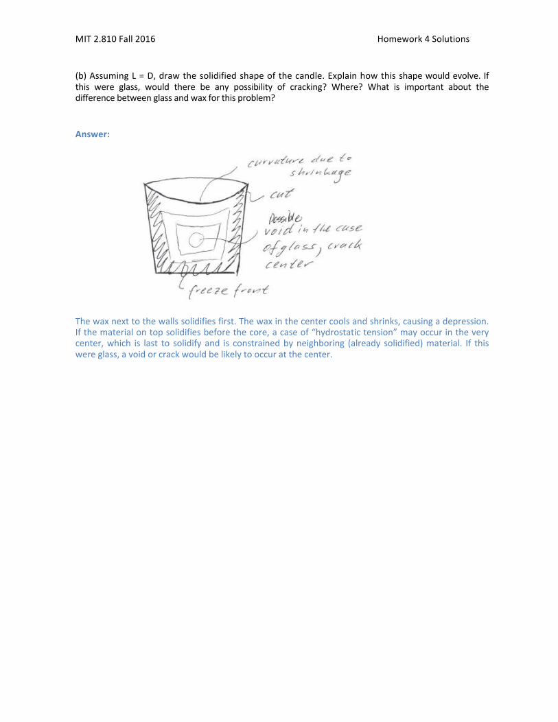
(b)AssumingL=D,drawthesolidifiedshapeofthecandle.Explainhowthisshapewouldevolve.Ifthis were glass, would there be any possibility of cracking? Where? What is important about thedifferencebetweenglassandwaxforthisproblem?Answer:
Thewaxnexttothewallssolidifiesfirst.Thewaxinthecentercoolsandshrinks,causingadepression.Ifthematerialontopsolidifiesbeforethecore,acaseof“hydrostatictension”mayoccurintheverycenter,which is last to solidify and is constrainedbyneighboring (already solidified)material. If thiswereglass,avoidorcrackwouldbelikelytooccuratthecenter.
MIT2.810Fall2016 Homework4Solutions
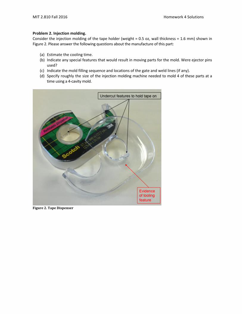
Problem2.Injectionmolding.Considertheinjectionmoldingofthetapeholder(weight=0.5oz,wallthickness=1.6mm)showninFigure2.Pleaseanswerthefollowingquestionsaboutthemanufactureofthispart:
(a) Estimatethecoolingtime.(b) Indicateanyspecialfeaturesthatwouldresultinmovingpartsforthemold.Wereejectorpins
used?(c) Indicatethemoldfillingsequenceandlocationsofthegateandweldlines(ifany).(d) Specifyroughlythesizeoftheinjectionmoldingmachineneededtomold4ofthesepartsata
timeusinga4-cavitymold.
Figure2.TapeDispenser

MIT2.810Fall2016 Homework4Solutions
Figure3.TapeDispenserDimensions
Answer:(a) Usingthevaluefor𝛼typicalforpolymersandthegivenwallthickness,
𝑡!""# ≈!!
!
!=
!.!" !" !
!"!!!!!/!= 6.4 𝑠
(b)Specialfeatures:
• 2undercutsrequirespecialtoolfeatures• Serratededge(neededtokeeptherolloftapefromfallingoff)requiressidepull• Stripperplateusedtoremovepart
Somefeaturesofthetoolingforthetapedispenser:

MIT2.810Fall2016 Homework4Solutions
(c)Moldfillingsequenceandlocationsofthegateandweldlines.(Note:Thisquestionpresumesthatyouhavethepartandcaninspectit.)
Gate

MIT2.810Fall2016 Homework4Solutions
(d)Machinerequirementstoinjectionmold4oftheseatatimeina4-cavitymoldareasfollows:Clampingforce:𝐹 = 𝑁!"#𝐴!"#$𝑃 = 4 2.5 𝑖𝑛 2.5 𝑖𝑛 14500 𝑝𝑠𝑖 = 362500 𝑙𝑏𝑠 = 1612 𝑘𝑁Shotsize:
𝑉!!!" = 𝑁!"#𝑉!"#$ = 𝑁!"#𝑚𝜌
= 40.5 𝑜𝑧 16 𝑜𝑧𝑙𝑏
0.05 𝑙𝑏𝑖𝑛!= 2.5 𝑖𝑛! = 41 𝑐𝑚!
Notes:Theprojectedareaisaroughestimate,sinceprecisedimensionsareunavailable.TheinjectionpressureisaroughaverageofallthepolymersgiveninBoothroyd,Table8.5(around1000bar=14500psi).Anaveragedensityforplasticsis~1500kg/m3=0.05lb/in3.Bothoftheseestimatesignoretherunners,whichwouldrequireadditionalclampingforce(astheprojectedareawillincrease)andaddvolumetotheshotsize.EstimatesfortheadditionalareaneededfortherunnersasafunctionofthepartvolumecanbefoundinBoothroyd,Table8.2.

MIT2.810Fall2016 Homework4Solutions
Problem3.Designforinjectionmolding.TwoconceptualdesignsforthetoolingforthepartshowninFigure3(aftereliminatingthe0.25in.ridgeatthebase)areshownindrawings(A)and(B).
(a) Whatwouldbethedifferencebetweenthesetwoapproaches?(b) DoanyfeaturesonthesedrawingsviolateDFMrules?(c) Drawinthelocationofthepartimmediatelyafteropeningthemold.(d) Pleaseshowwhereyouwouldputastripperplateand/orejectorpinsonthesemolds.(e) Considertwodifferentgatingsituations.Ononedrawthegateandspruelocationiftheyare
toremainconnectedtothepartondieopening.(f) In another, show the gate and sprue location if they are to separate from the part on die
opening.
Figure3.Injectionmoldedpart(alldimensionsininches).

MIT2.810Fall2016 Homework4Solutions

MIT2.810Fall2016 Homework4Solutions
AnswertoProblem3,partb.Somepossibledesignalternationsforimprovedmanufacturing:
1. Addadraftangleandroundcorners2. Makeallwallsthesamethickness3. Elminate“overhang”wherepossible
Estimateofpartcycletime:
𝑡 ≅ 𝐻!
𝛼=
0.635𝑐𝑚2
!
10!!!"!
!"#
= 101 𝑠𝑒𝑐
This cycle time is too long, so would want to redesign the parts with thinner walls, and ribs ifnecessaryforstiffness.Clampingforce(notnecessaryforthisproblem,justforyouredification)𝑃𝑟𝑜𝑗𝑒𝑐𝑡𝑒𝑑 𝐴𝑟𝑒𝑎 ≅ 4.50 + 0.50 ∗ 3.50 + 0.50 ≅ 20𝑖𝑛! + 𝑟𝑢𝑛𝑛𝑒𝑟𝑃𝑟𝑒𝑠𝑠𝑢𝑟𝑒 ≅ 7000𝑝𝑠𝑖𝐶𝑙𝑎𝑚𝑝 𝑓𝑜𝑟𝑐𝑒 ≅ 20𝑖𝑛! ∗ 7000 !"
!"! = 140,000𝑙𝑏𝑠 = 70 𝑡𝑜𝑛𝑠

MIT2.810Fall2016 Homework4Solutions
Problem4.Diecastingversusinjectionmolding.Onenoticeabledifferencebetweendiecastingtoolingandinjectionmoldingtoolingisthesizeoftherunnersystem.Figure4showsamulti-cavitydiefordiecasting.Notethattherunnersystemisquitelargeandchanginginsize.Incomparison,therunnersystemforinjectionmoldingisusuallyofsmallerandconstantdiameter.Canyouexplainwhythesearedifferent?Isthereafeatureofthediecastingdiethatismissinginthispicture?
Figure4.Multiple-cavitytoolfordiecasting.Notetherunnersizecomparedtopartsize.AnswerConsidertransportrate/coolingrate(units1/time)
𝑡𝑟𝑎𝑛𝑠𝑝𝑜𝑟𝑡: 1𝑡~𝑉𝐿!
𝑐𝑜𝑜𝑙𝑖𝑛𝑔: 1𝑡~
𝛼
(𝐿!2 )!
𝑡ℎ𝑒𝑛 𝑡𝑟𝑎𝑛𝑠𝑝𝑜𝑟𝑡𝑐𝑜𝑜𝑙𝑖𝑛𝑔
= 14𝑉𝐿!𝛼
∙𝐿!𝐿!
Typicalvaluesforinjectionmolding:
1410!"! 0.1𝑐𝑚
1𝑥10!!!"!
!
∙0.1𝑐𝑚10𝑐𝑚
≅ 2.5
Thisshowsthatthetworates(transportandcooling)areaboutequal,withinanorderofmagnitudeTypicalvaluesfordiecasting:
1410!"! 0.1𝑐𝑚
0.3!"!
!
∙0.1𝑐𝑚10𝑐𝑚
≅ 10!!
Hence for die casting the heat transfer rate ismuch faster andwith a thin runner system there isdangerofsolidifyingbeforethemoldsarefilled.Note:theactualsituationisbetterthanthisbecausetheheattransferrateissmallerthancalculatedaboveduetofilmresistance.Alsonote:themulticavitytoolfordiecastingshowninFig4doesnothaveoverflowwells,whicharecommonlyused.SeeDesignforDieCastingbyBoothroyd.

MIT2.810Fall2016 Homework4Solutions
Problem5.Coolingtime.Showthatequation8.5inBoothroydetal.reducestoourresult
𝑡! = (!/!)!
!at𝜃 = !!!!!
!!!!!= 0.1
Answer:TheequationinBoothroydis:
𝑡! =ℎ!"#!
𝜋!𝛼ln4 𝑇! − 𝑇!𝜋 𝑇! − 𝑇!
where𝑇! =recommendedinjectiontemperature𝑇!=recommendedejectiontemperature𝑇!=recommendedmoldtemperatureSubstitutingintoBoothroyd’sequation𝜃 = 0.1gives
𝑡! =ℎ!"#!
𝛼∙1𝜋!ln
4𝜋∙ 10 = 0.258 ∙ (
ℎ!"#!
𝛼) ≅
(ℎ!"#2 )!
𝛼