mit mit icat - massachusetts institute of technology
TRANSCRIPT

MIT MIT ICAT ICAT
AIR CARRIER FLIGHT OPERATIONS
Alan H. Midkiff
R. John Hansman
Tom G. Reynolds
Report No. ICAT-2004-3
July 2004
MIT International Center for Air Transportation Department of Aeronautics & Astronautics
Massachusetts Institute of Technology Cambridge MA 02139 USA

Air Carrier Flight Operations
by
Alan H. Midkiff, R. John Hansman & Tom G. Reynolds
International Center for Air Transportation
Department of Aeronautics & Astronautics
Massachusetts Institute of Technology
Cambridge MA 02139 USA
Report No. ICAT-2004-3
July 2004
© 2004 Massachusetts Institute of Technology. All rights reserved.
2

TABLE OF CONTENTS
1. Introduction........................................................................................................................... 4 2. Regulation & Scheduling...................................................................................................... 4
2.1. General Regulatory Requirements .................................................................................... 4 2.2. Flight Crew Regulation ..................................................................................................... 5 2.3. Flight Crew Scheduling..................................................................................................... 7
3. Flight Crew Activities During a Typical Flight.................................................................. 8
3.1. Flight Crew Sign-in ........................................................................................................... 8 3.2. Operations/Planning .......................................................................................................... 8 3.3. Pre-flight.......................................................................................................................... 13 3.4. Pre-departure ................................................................................................................... 21 3.5. Gate Departure ................................................................................................................ 22 3.6. Taxi-out ........................................................................................................................... 24 3.7. Take-off ........................................................................................................................... 25 3.8. Terminal Area Departure................................................................................................. 26 3.9. Climb ............................................................................................................................... 27 3.10. Cruise............................................................................................................................... 28 3.11. Descent ............................................................................................................................ 30 3.12. Terminal Area Arrival ..................................................................................................... 33 3.13. Final Approach ................................................................................................................ 34 3.14. Landing and Rollout ........................................................................................................ 36 3.15. Taxi-in ............................................................................................................................. 37 3.16. Parking............................................................................................................................. 38 3.17. Post-flight ........................................................................................................................ 39
4. Summary.............................................................................................................................. 39
3

AIR CARRIER FLIGHT OPERATIONS
by
Alan H. Midkiff, R. John Hansman & Tom G. Reynolds MIT International Center for Air Transportation
1. Introduction Most air carriers operate under a system of prioritized goals including safety, customer service (on-time departures and arrivals) and operating economics. The flight operations department is responsible for the safe and efficient movement of passengers and/or cargo which ultimately generate the revenue for the airline. The major components needing to be coordinated for any given flight include the aircraft and support equipment, cockpit and cabin crews (together known as the “flight crew”), maintenance, and ground service personnel. Although the maintenance and ground crew activities are critical to support flight operations, the emphasis in this document is on the regulation and scheduling of the flight crews to conduct a given flight, followed by a detailed discussion of the activities of flight crews during the phases of a typical revenue flight sequence. Note that this chapter does not attempt to address detailed airmanship and flight maneuvering topics and only includes such information in the context of the overall flight operation. However, specific flight procedures that may have a direct impact on the operational goals are included to aid in understanding the nature and complexity of the factors involved. 2. Regulation & Scheduling 2.1. General Regulatory Requirements Air carrier operations are generally regulated by the country of registration and the sovereignty in which the operation is conducted, including the Federal Aviation Administration (FAA) in the USA and the Joint Aviation Authority (JAA) in Europe. International flights may also fall under the jurisdiction of ICAO (International Civil Aviation Organization) when operating abroad1. In the US, the Code of Federal Regulations (CFR Section 14)2 Parts 119, 121, and 135 cover commercial operations3, while Part 91 addresses general operating and flight rules. Parts 61, 65
1U.S.-based carriers are governed by both when conducting international operations. 2Previously known as Federal Aviation Regulations (FARs). 3Part 119 governs the certification for air carriers and commercial operators; Part 121 governs operating
requirements for domestic, flag and supplemental operations (generally commercial operations with > 30 seats), while Part 135 governs the operating requirements for commuter and “on-demand” air-taxi operation.
4

and 67 govern aircrew certification4. Many large airlines also utilize fleet-specific flight operation guidelines under agreements with the local governing authorities. 2.2. Flight Crew Regulation The principal human component of flight operations is the flight crew, comprising both cabin and cockpit crews. At large carriers, personnel rosters for cabin and cockpit crews may exceed 20,000 and 10,000 employees respectively. In many cases crewmembers may have never worked together prior to a particular flight. In order to maintain a safe, efficient, and smoothly functioning operation, airlines and regulators have developed very detailed procedures to be executed by the crewmembers with little room for improvisation. These procedures, including normal, abnormal and emergency conditions, are detailed in the crewmembers’ operating manuals5 and backed up through a system of checklists which are cross-checked between flight crewmembers. It is the responsibility of the training or flight standards department to establish crewmember proficiency and currency. The Captain, however, is always ultimately responsible for the safe and efficient conduct of the flight and in extraordinary circumstances may deviate from a procedure or regulation under his or her command authority (Captain’s Emergency Authority). The cabin crew is primarily responsible for passenger safety during the flight. Other duties include providing customer service products (meals, entertainment, etc.) and assistance with boarding. Flight attendants receive specialized training in aircraft emergencies, evacuation procedures, medical issues and health hazards, care of special needs passengers, flight regulations and meal service. Most flight attendants’ pre-airline experience includes some type of customer service, medical care, or marketing background. Post high school education is preferred but not required. A flight attendant’s initial training regime usually lasts 4 to 7 weeks including final in-flight experience. Cabin crews are required to undergo annual recurrent training for each of the aircraft they are qualified on. The number of flight attendants assigned to a given flight vary with the seats available on the aircraft, and their working agreement. Minimum FAA staffing requirements include 1 flight attendant for a seating capacity greater than 19 but less than 51; 2 flight attendants for capacities greater than 50 but less than 101 seats; and 2 flight attendants plus one additional flight attendant for every 50 seats (or fraction of 50) above 100. Most airlines today operate equipment requiring a cockpit crew of two pilots: the Captain in the left cockpit seat and First Officer (FO) in the right cockpit seat. Older aircraft (such as 747-100/200 “Classics”, DC-10, 727) may also require a Flight Engineer to manage the systems which are now automated in newer airplanes. In addition, an augmented crew of relief pilots may be required to staff long-haul flights due to duty time restrictions imposed by working agreements and/or regulations. Although the Captain is always Pilot-In-Command (PIC), 4Part 61 governs certification of pilots, flight instructors and ground instructors; Part 65 governs certification of
airmen other than flight crewmembers and Part 67 governs medical standards. 5The Standard Operating Procedures (“SOP”) of an air carrier are detailed in a number of documents including the
generalized flight manual (non fleet-specific operating rules), flight procedures (Jeppesen or other approach and navigation publications), Minimum Equipment List (MEL-described later in this document), aircraft-specific operating manuals and performance manuals.
5

augmented crewmembers must also hold an Airline Transport Pilot (ATP) type-rating certification6 in the aircraft to meet the requirement that a licensed type-rated pilot is always at the controls during the Captain’s rest period. In the US, many flight deck crews at Part 121 carriers have experienced some level of military flight training either through regular, reserve or air guard duty. Many maintain their reserve or guard status while employed by the airline and must accommodate their military duty requirements while flying full-time. Civilian pilots come from a variety of backgrounds including commuter/regional, corporate and general aviation. A pilot’s flight experience is primarily measured in hours of flying time which is further detailed by type of aircraft and conditions of flight. Typical “new hire” flight experience ranges from 1500 to 5000 hours, including 1000 hours of multiengine and/or jet time. Military pilots tend to be in the lower range because of the type of specialized flying they perform and the means by which they log their flight hours. Ab initio training programs are offered by some educational institutions (including airline training departments) which train pilots with limited or no flight experience to a level of proficiency with which they can operate as part of a flight crew, usually at a regional airline. Many non-U.S. carriers use this type of training for their flight crews and often send them to the U.S. to offset the higher costs associated with operating in their respective airspace. Cockpit crews typically have at least a 2 year college education with most having a four year degree. Cockpit crews require licensing by their respective national authorities, including some level of commercial/transport certification as well as individual qualifications in specific aircraft for larger types (type-ratings). Crews must complete the training regimen established by their airline before meeting the qualification requirements for operating that carrier’s aircraft. Initial qualification training durations vary between aircraft but usually require 4 to 6 weeks, including ground training and simulator sessions. Improved simulator technology precludes the utilization of actual aircraft during flight training in all but the most unusual circumstances. The simulators can safely replicate a wide variety of environmental, flight and mechanical conditions in order to achieve flight crew proficiency in both normal and abnormal procedures. In almost all cases, the first instance a pilot operates the controls of an actual aircraft is on a revenue flight with paying passengers aboard7. It should be noted, however, that as advanced as simulator technology has become, not all tactile and visual stimuli can be entirely replicated, resulting in the aircraft being easier to operate than the simulator. Recurrent training cycles also contain both ground and simulator components and, depending on the carrier’s self-administered FAA-approved program (in U.S.), usually occur on a 6, 9, 12 or 24 month basis. In most airlines, flight crews also participate in Crew Resource Management (CRM) training as part of their recurrent itinerary. CRM is the effective use by the flight crew of all resources to
6Large aircraft require certification in the specific type, i.e. B-777, as opposed to smaller airplanes which are
covered under a broader system of categories and classes, for example, multiengine land, or single engine sea. These ratings are added to pilots’ licenses which are comprised of different grades including private, commercial, or airline transport pilot (ATP). ATP grade certification or equivalent is required to act as PIC of air carrier aircraft.
7Before a crewmember can conduct unsupervised flight duties, he must complete the final phase of flight training which is usually referred to as Initial Operating Experience (IOE) or Line Operating Experience (LOE). This phase of a pilot’s qualification consists of the first 15 to 25 hours of actual flight time, and is conducted under the supervision of a check airman who acts as the legal PIC (regardless of whether he occupies the left or right seat).
6

include human and other aviation systems, specifically flight attendants, dispatchers, maintenance, ground/gate personnel and Air Traffic Control (ATC). CRM training emphasizes the skills necessary to optimize the human/machine interface including situation awareness, use of automation systems, team building, task delegation, information transfer, problem solving, and decision-making. Pilots are also required to maintain a minimum health standard which is validated by a licensed medical examiner. Crewmembers are subject to periodic flight physicals on a recurring basis (6 or 12 months in U.S.), which is determined by the certification requirements commensurate with their flight duties. However, a pilot’s “fit-to-fly” decision for a given flight is based on a self-assessment of their current physical and mental condition and may result in the crewmember temporarily disqualifying themselves for flight activities. In addition, specified guidelines concerning other activities including alcohol consumption, prescription drug use, blood donation and scuba diving must be adhered to and may also result in restrictions from flight duties. At most air carriers, flight crews are represented by labor unions which negotiate collective bargaining agreements. The work rules contained in these contracts are usually more restrictive than those imposed by federal regulations and are driven by both safety and labor considerations. The collective bargaining process always has the potential of disrupting the carrier’s operations and consideration must be given with respect to the effect of a work stoppage by one group on the others. 2.3. Flight Crew Scheduling Cockpit and cabin crews are assigned duty to a given flight by a variety of means. The majority of crewmembers are assigned to a flight as part of their normal schedules or “lines”. A line of flying describes a crewmembers flight activity for some period (typically a month), and consists of sequences of flight duty and days off (e.g. three days on, two days off). These “bid lines” are proffered by the company based on the flying requirements for a given crew base, then awarded in order of seniority through the bidding process. Bid lines may range from 65 to 85 hours spread over 10 to 18 duty days, depending on the carrier’s working agreement. A typical duty day consists of 1 to 4 flight legs, however, on some duty days the crew may operate none at all (sit at hotel), or fly more than five legs. Each package of bid lines targets a specific flying “job” which may include crew base, equipment type, seat (Captain, First Officer, etc.), and division, (e.g. LaGuardia – B767 – Captain – International). Flying job assignments are also based on seniority in accordance with crewmembers’ preferences. Many departures require filling an “open seat” because of a sick call, vacation, misconnect (including “commuting” crewmembers who reside out of base), legality (duty time) issues, or that the job was never assigned as part of the normal bid process (open time). It is the responsibility of the crew scheduling department to fill these open seats and satisfy the manning requirements for each flight. Open time can be proffered or traded with other lineholders8, or assigned to reserve crews. Each bid position has a contingency of reserve crewmembers who are 8Lineholders are crewmembers whose monthly schedule consists of a bidline, as opposed to reserve crewmembers
whose monthly schedule consists of days of availability and days off.
7

“on call” and available for the company to use on short notice (in some cases ready reserves are standing by at the airport). Once the first flight of a crew sequence departs, manning responsibility shifts from crew schedule to crew tracking who intercede in cases of mid-sequence disruptions including illness, misconnects, equipment problems and cancellations. 3. Flight Crew Activities During a Typical Flight A typical revenue flight involves the flight phases illustrated in Figure 1. The flight crew activities involved in each of these phases are described in detail in the following sub-sections, numbered according to the phases outlined in the figure. The primary focus is on the cockpit crew activities, but cabin crew activities are also discussed where relevant.
1. Flight crew sign-in2. Operations/Planning
3. Pre-flight4. Pre-departure5. Gate departure
6. Taxi-out
7. Take-off
8. Terminal areadeparture
9. Climb
10. Cruise
11. Descent
12. Terminal areaarrival
13. Final approach
14. Landing& Roll-out
15. Taxi-in
16. Parking
17. Post-flight
ORIGINAIRPORT
DESTINATIONAIRPORT
Figure 1: Typical Flight Phases
3.1. Flight Crew Sign-in Once assigned to a flight sequence, crewmembers are required to sign in at the station flight operations office (nominally) one hour prior to the departure of the first leg. Crews normally arrive earlier than one hour in order to accommodate international flight planning, publication/flight manual updating, or other administrative responsibilities. Once introductions between crewmembers are complete, the flight crew begins the planning tasks. In situations where the time available before departure is minimal, the First Officer may proceed to the aircraft to begin the preflight duties there, while the Captain completes the requisite paperwork in the flight operations office. 3.2. Operations/Planning Most airlines have a central Airline Operations Center (AOC) staffed by certified flight dispatchers. The flight dispatchers’ duties include the planning and flight following for as many as 20 (or more) concurrent flights. The flight planning task involves selecting the optimal routing (minimum time, minimum fuel, best ride conditions, etc.), and generating a “flight plan” which takes into consideration aircraft type, weather conditions during all phases, aircraft loads and operating weights, aircraft mechanical condition, marketing constraints, and airport
8

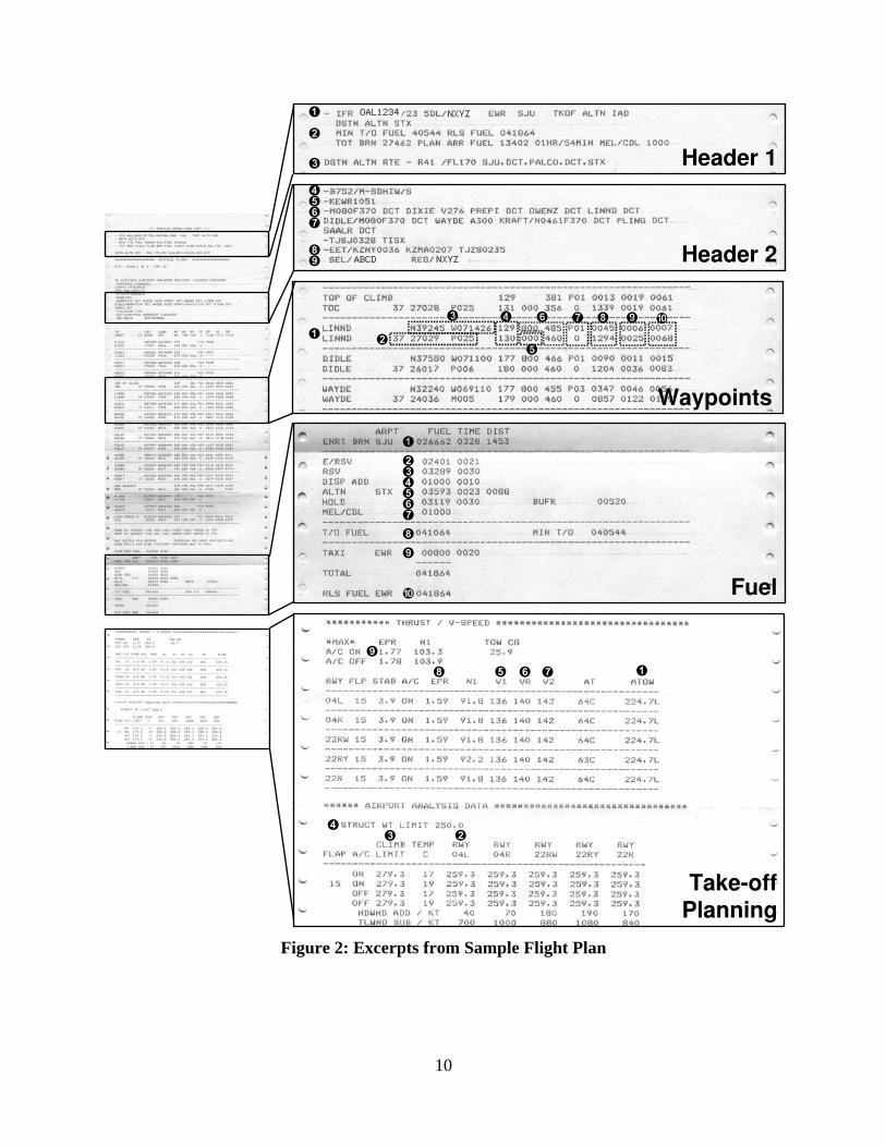
limitations and curfews. It also includes evaluating the take-off and landing performance which is discussed in more detail later. The flight plan is the means by which the dispatcher communicates the details of a flight to the cockpit crew and is usually available for retrieval via computer terminal/printer approximately one hour before departure time. The flight plan details various aspects of the flight, such as routing, weather, alternate airport options, fuel requirements, take-off performance and loads (which are subject to last minute changes). The flight plan is printed out and its details are examined by the incoming cockpit crew. Concurrence is typically indicated by the Captain’s signature on the paper or electronic “station copy” of the flight plan. In many cases, no direct communication with the dispatcher is necessary unless changes in fuel load or routing, weather, aircraft operational status/mechanical discrepancies and/or any anticipated delays need to be discussed. Excerpts from a sample flight plan for a flight from Newark, NJ (EWR/KEWR) to San Juan, Puerto Rico (SJU/TJSJ) are illustrated in Figure 2. Contents of the major sections of this sample flight plan (Header, Waypoints, Fuel and Take-off Planning) are described in detail below.
3.2.1. Header The flight plan header contains the flight plan summary and information concerning aircraft type and registration, the filed routing, planned cruise Mach/altitude and the en-route ATC sectors to be traversed. In the sample flight plan, this information is as follows:
1. Flight Plan summary = IFR flight plan for flight OAL1234, registration NXYZ from Newark (EWR) to San Juan (SJU) with take-off alternate Washington Dulles (IAD) and destination alternate St. Croix (STX)—see later alternate discussion.
2. Fuel summary 3. Alternate destination routing = SJU direct to STX via PALCO 4. Aircraft type = B757-200 followed by aircraft equipage codes 5. Departure from Newark (ICAO code KEWR) at 10:51am Universal Time (UT) 6. Cruise Mach = 0.80
Cruise altitude = 37,000 ft Filed routing = direct to waypoint DIXIE; then via Victor airway V276 to waypoint PREPI; then direct to waypoints OWENZ, LINDD, DIDLE (the oceanic entry point, after which maintain Mach 0.8 and FL370) and WAYDE; then via oceanic airway A300 to KRAFT (after which maintain 4612 knots); then direct to waypoints PLING and SAALR
7. Destination = San Juan (ICAT code TJSJ), estimated en-route flight time = 3 hours 28 minutes, destination alternate = St. Croix (ICAO code TISX)
8. Estimated flight time to ATC sector boundary crossing = 36 minutes (NY sector (KZNY)); 2 hours 7 minutes (Miami sector (KZMA)); 2 hours 35 minutes (San Juan sector (TJZS))
9. Aircraft registration = NXYZ with SELCAL designation ABCD (see later)
9
Header 2
Waypoints
Fuel
Take-offPlanning
NXYZ
NXYZ OAL1234
Header 1
ABCD
Figure 2: Excerpts from Sample Flight Plan
10

3.2.2. Waypoints The body of the flight plan contains specific information corresponding to each waypoint in the filed route, including the flight level/altitude, wind aloft forecast, course/heading, Mach/airspeed/groundspeed, terrain elevation data, forecast turbulence, temperature deviation from standard, segment/cumulative distance, segment/cumulative flight time, segment/cumulative fuel burn. In the sample flight plan, the following information is given at waypoint LINDD:
1. Waypoint ID = LINDD 2. Flight level = 370 (37,000 feet) with wind = 270° at 29 knots and wind
component relative to course = 25 knots tailwind 3. Latitude/longitude = N39°24.5’/W071°42.6’ 4. Magnetic course to LINDD = 129°, magnetic heading (course adjusted for wind)
= 130° 5. Terrain height = 000 (sea level) 6. Mach = 0.80, true airspeed (TAS) = 460 knots, groundspeed (GS, TAS adjusted
for wind component) = 485 knots 7. Temperature deviation from (ISO) standard = +1 deg C & turbulence index = 0
(mostly smooth or better) 8. Distance from previous waypoint = 45 nm & total distance remaining = 1294 nm 9. Segment time from previous waypoint = 6 minutes & total flight time from
departure point to LINDD = 25 minutes 10. Segment fuel burn = 700 lb & total fuel used from departure to LINDD = 6800 lb
3.2.3. Fuel One of the key factors in flight planning is determining the fuel load. It is also critical to finalize the fuel quantity required as early as possible because of the inherent delay in the ordering and appropriation of fuel. Considerations in determining the fuel load include: fuel to destination including reserves (which vary depending on the type of flight, e.g. overwater), destination weather and alternates, off-optimum speed or altitude requirements (which may be driven by marketing or ride conditions), ferrying fuel to destinations where it is cost effective and mechanical discrepancies of the aircraft. The fuel load will also affect take-off and landing performance and may influence the payload the aircraft can carry. Information regarding fuel load is provided in the fuel section of the flight plan illustrated in Figure 2.
11. Total fuel/time/distance from EWR to SJU = 26,662 lbs/3 hrs 28 mins/1453 nm 12. Enroute reserves required for overwater operations = 2401 lb/21 mins (10% of the
flight time) 13. Regular reserves = 3289 lbs/30 min 14. Dispatch addition = 1000 lb/10 min (account for possible en-route chop as
indicated in remarks) 15. Fuel to get to destination alternate (St. Croix (STX)) = 3593 lb/23 min/88 nm 16. Holding fuel = 3119 lb/30 min 17. MEL/CDL fuel (757/767 fuel pump airworthiness directive adjustment) = 1000 lb 18. Take-off fuel = 41,064 lb
11
19. Taxi from gate to runway at EWR (including anticipated delays) = 800 lb/20 min 20. Total fuel load at release from EWR = 41,864 lb
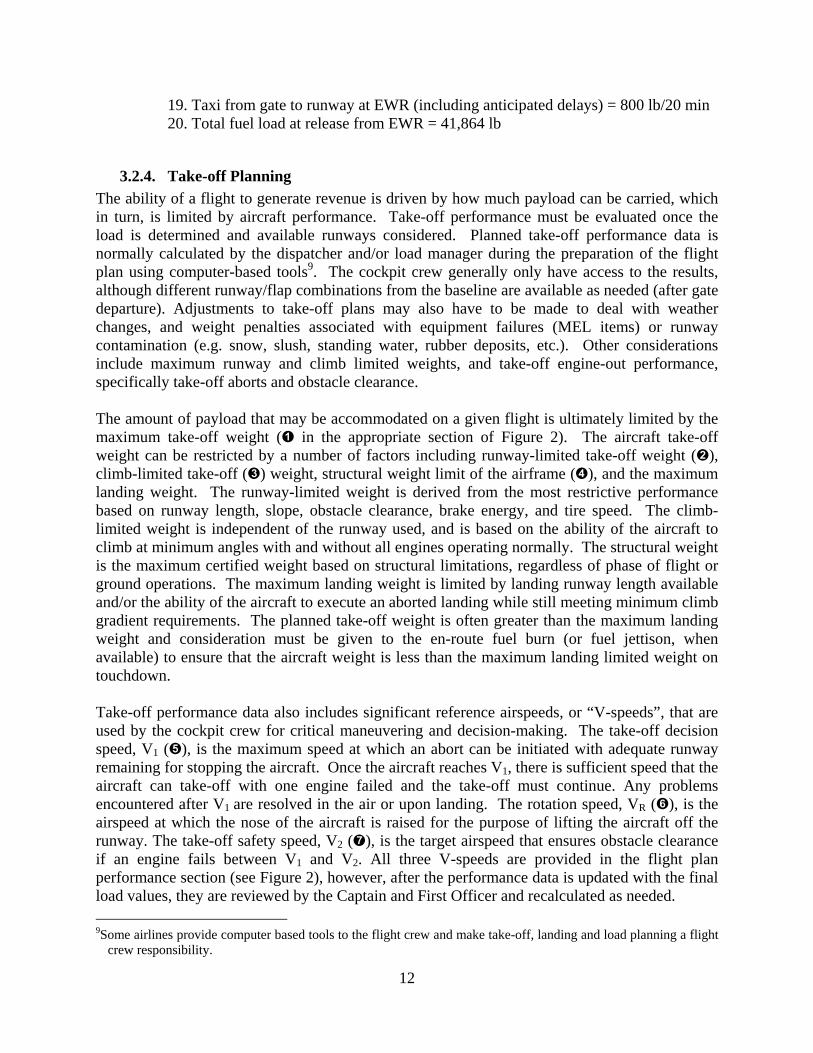
3.2.4. Take-off Planning The ability of a flight to generate revenue is driven by how much payload can be carried, which in turn, is limited by aircraft performance. Take-off performance must be evaluated once the load is determined and available runways considered. Planned take-off performance data is normally calculated by the dispatcher and/or load manager during the preparation of the flight plan using computer-based tools9. The cockpit crew generally only have access to the results, although different runway/flap combinations from the baseline are available as needed (after gate departure). Adjustments to take-off plans may also have to be made to deal with weather changes, and weight penalties associated with equipment failures (MEL items) or runway contamination (e.g. snow, slush, standing water, rubber deposits, etc.). Other considerations include maximum runway and climb limited weights, and take-off engine-out performance, specifically take-off aborts and obstacle clearance. The amount of payload that may be accommodated on a given flight is ultimately limited by the maximum take-off weight ( in the appropriate section of Figure 2). The aircraft take-off weight can be restricted by a number of factors including runway-limited take-off weight (), climb-limited take-off () weight, structural weight limit of the airframe (), and the maximum landing weight. The runway-limited weight is derived from the most restrictive performance based on runway length, slope, obstacle clearance, brake energy, and tire speed. The climb-limited weight is independent of the runway used, and is based on the ability of the aircraft to climb at minimum angles with and without all engines operating normally. The structural weight is the maximum certified weight based on structural limitations, regardless of phase of flight or ground operations. The maximum landing weight is limited by landing runway length available and/or the ability of the aircraft to execute an aborted landing while still meeting minimum climb gradient requirements. The planned take-off weight is often greater than the maximum landing weight and consideration must be given to the en-route fuel burn (or fuel jettison, when available) to ensure that the aircraft weight is less than the maximum landing limited weight on touchdown. Take-off performance data also includes significant reference airspeeds, or “V-speeds”, that are used by the cockpit crew for critical maneuvering and decision-making. The take-off decision speed, V1 (), is the maximum speed at which an abort can be initiated with adequate runway remaining for stopping the aircraft. Once the aircraft reaches V1, there is sufficient speed that the aircraft can take-off with one engine failed and the take-off must continue. Any problems encountered after V1 are resolved in the air or upon landing. The rotation speed, VR (), is the airspeed at which the nose of the aircraft is raised for the purpose of lifting the aircraft off the runway. The take-off safety speed, V2 (), is the target airspeed that ensures obstacle clearance if an engine fails between V1 and V2. All three V-speeds are provided in the flight plan performance section (see Figure 2), however, after the performance data is updated with the final load values, they are reviewed by the Captain and First Officer and recalculated as needed. 9Some airlines provide computer based tools to the flight crew and make take-off, landing and load planning a flight
crew responsibility.
12

In many cases, the actual planned take-off weight is well below any of the previously mentioned limitations, or those imposed by aborted take-off considerations. In these cases it is often beneficial to take-off at reduced or “de-rated” thrust to minimize engine wear and noise. The balanced field length for a given take-off weight is defined as the distance required to accelerate to V1 and safely stop the aircraft on the remaining runway or continue the take-off so as to reach V2 by 35 feet above the take-off surface at the end of the runway. If the balanced field length is less than the actual runway available, the engine thrust settings used for a departure () may be de-rated by a calculated amount up to 25% from the maximum available () while still meeting take-off safety limits. The reduced take-off thrust parameters are included in the performance data. It is, however, not always wise to perform a de-rated take-off. Conditions that preclude a de-rated take-off include: reports of windshear, tailwind, anti-icing fluid applied, runway contamination, equipment failures or noise consideration. Often the decision to use max power is not finalized until reaching the departure runway after taxi-out.
3.2.5. Alternate Airports Although the intent of every departure is to land at the published destination airport, contingencies such as weather or traffic may require an alternate destination airport. In the sample flight plan, alternates and routes to get there are listed in the header section. Take-off, en-route, and destination alternate airports are stipulated to satisfy certain weather requirements or routing limitations. Take-off alternates are required whenever the option to return to the departure airfield is in question. The criteria for determining the necessity for a take-off alternate is often driven by the possibility of downgraded operational status of the aircraft (engine-out approach minimums), or the fact that take-off weather requirements are often less restrictive than landing weather requirements. Additionally, take-off alternate options are normally limited to within a certain distance of the departure airfield (i.e. 360 nm). Enroute alternates are required when operational considerations dictate specialized contingency diversion procedures such as an engine-out, loss of cabin pressurization over mountainous terrain, or diversions while operating over-water. Enroute alternates and diversion decision-making are discussed in further detail later in the chapter. Destination alternate requirements are driven by forecast weather conditions at the airport of intended landing, and in cases where weather conditions are good and not expected to be a factor, no alternate may be required. The requirements to include destination alternate(s) in the flight plan are determined by the forecast weather and approach navigational facilities at the destination airport. If the weather is forecast to go below certain minimums, an alternate is stipulated in the flight planning process, including the extra fuel to fly from the destination to the alternate, plus 30 or 45 minutes reserve fuel depending on the type of operation. The suitability of an alternate airport is also limited by forecast weather and approach procedures available. 3.3. Pre-flight The crew must determine the airworthiness of the aircraft and address any open issues before departure. The term “preflight” is typically used to describe the interior and exterior inspections of the aircraft, but in a general sense can be used to describe any activity involved with preparing the aircraft for departure. The aircraft inspection is usually divided among the cockpit crew and includes an exterior walkaround examination, interior cockpit set-up, and systems checks. These
13
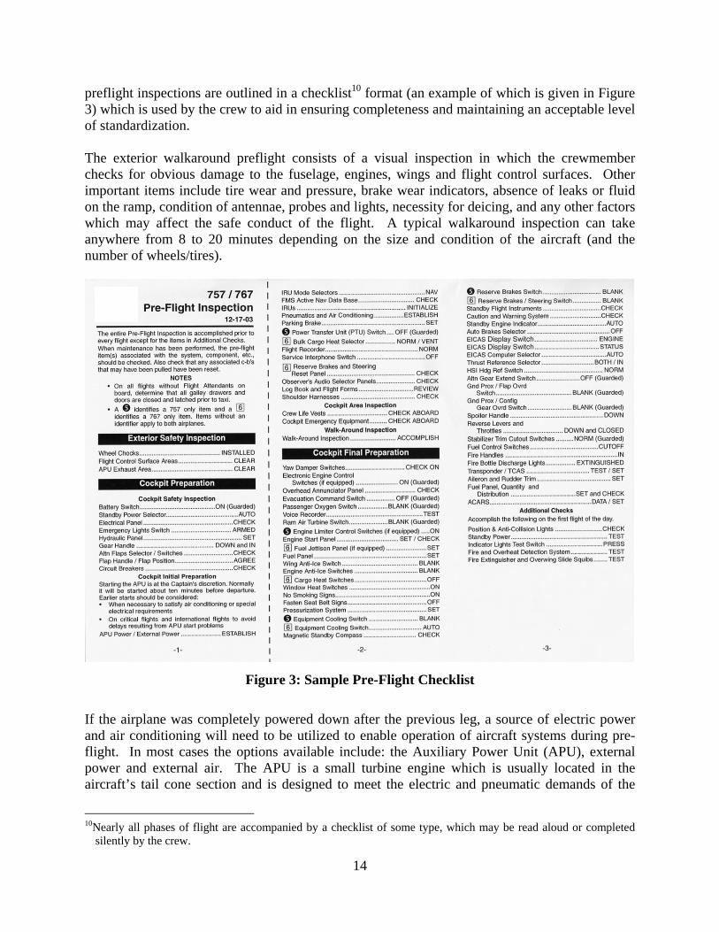
preflight inspections are outlined in a checklist10 format (an example of which is given in Figure 3) which is used by the crew to aid in ensuring completeness and maintaining an acceptable level of standardization. The exterior walkaround preflight consists of a visual inspection in which the crewmember checks for obvious damage to the fuselage, engines, wings and flight control surfaces. Other important items include tire wear and pressure, brake wear indicators, absence of leaks or fluid on the ramp, condition of antennae, probes and lights, necessity for deicing, and any other factors which may affect the safe conduct of the flight. A typical walkaround inspection can take anywhere from 8 to 20 minutes depending on the size and condition of the aircraft (and the number of wheels/tires).
Figure 3: Sample Pre-Flight Checklist
If the airplane was completely powered down after the previous leg, a source of electric power and air conditioning will need to be utilized to enable operation of aircraft systems during pre-flight. In most cases the options available include: the Auxiliary Power Unit (APU), external power and external air. The APU is a small turbine engine which is usually located in the aircraft’s tail cone section and is designed to meet the electric and pneumatic demands of the
10Nearly all phases of flight are accompanied by a checklist of some type, which may be read aloud or completed
silently by the crew.
14

aircraft when the main engines are shutdown11. However, if external air and power are available for the aircraft, they will often be used in lieu of the APU to save on fuel and maintenance costs. External electric power may be provided to the aircraft either by a cable from the jetbridge, or from a power cart (see Figure 4). External low pressure conditioned air can be provided through a flexible duct to the belly of the aircraft or from a dedicated unit mounted to the jetbridge. External high pressure air may be provided to the aircraft by one or more air “start” carts for the purpose of starting an engine (also shown in Figure 4). Optimally, the station will provide external power and conditioned air from the jetbridge units until 5-10 minutes prior to departure when the crew will switch over to internal (APU) power.
PASSENGERJETBRIDGE
TOW TRUCK“TUG”
ELECTRICALCART
GALLEY SERVICE(1ST POSITION)
BULKCARGOLOADER
BULK CARGOTRAILER
FUELTRUCK
BULK CARGOTRAILER
BULKCARGOLOADER
GALLEY SERVICE(2ND POSITION)
POTABLEWATER
CABINCLEANING
LAVATORY
PNEUMATICCART
A/C
Figure 4: Typical Aircraft Ground Services
Once electrical power and air are available on the aircraft, interior preflight and cockpit “cleanup” checklists are conducted to confirm that each system is operational. Some of these systems employ self-tests (fire warnings), while others only require verification that acceptable parameters are satisfied (e.g. oil quantity). Some systems may require an initialization procedure such as Inertial Reference Unit (IRU) alignment. The cabin crew also have certain preflight
11The APU may also provide supplementary air/electric during abnormal situations such as engine/generator failure
or high altitude operations.
15

duties which include checking the status of catering and cabin emergency equipment, as well as general cabin condition. The preflight also includes verification that all required manuals and paperwork are onboard and complete. The aircraft mechanical logbook (Figure 5) serves as a means for flight and cabin crews to convey mechanical discrepancies to station maintenance personnel and subsequent flight crews. Any discrepancy entered into the logbook must be balanced with an entry by a certified aircraft mechanic12 who either resolve the problem or defer it according to specified guidelines. Some items can be deferred based on time (hours of flight, or days/weeks), type of maintenance available, or whether they are listed in the Minimum Equipment List (MEL). The MEL identifies the components which may be inoperative on a given aircraft while still maintaining legality for dispatch as well as the deferral rules. An example from an MEL is presented in Figure 6.
Mechanicaldiscrepancydescription
Actiontaken and
“sign-off” bycertified
mechanic
Figure 5: Example Mechanical Logbook Page
Crew responses associated with MEL items range from simple awareness to complex critical procedural changes. An example of a trivial MEL would be a burned out navigation light (2 available), which involves no performance penalty or crew procedures (except to remember to select the operative one). The deactivation of a wheel brake would be considered a critical MEL item. In this situation only one deactivation is allowed and dispatch must include a major weight penalty in the take-off planning. It is the cockpit crew’s responsibility to familiarize themselves with any procedural changes that result from an MEL item. The Configuration Deviation List (CDL) is similar to the MEL, but references airframe components that are more structural in nature (e.g. missing flap track fairing).
12If company maintenance is unavailable at the station, an outside contractor is used. Maintenance personnel handle discrepancies, perform required inspections and logbook endorsements which may be mandated for certain international flights.
16

Figure 6: Minimum Equipment List (MEL) Sample Page
Modern aircraft have extensive autoflight capabilities that allow many of the navigation13 and performance optimization tasks to be handled automatically if desired. Autoflight initialization and Flight Management System (FMS) programming are conducted during the pre-flight phase. Use of automation has been the focus of recent human factors research which has resulted in air carriers adopting “automation policies”. These policies attempt to address workload and situation awareness issues which have proven to be contributing factors in some aircraft accidents and incidents. In general, operating philosophies are being included in flight training that emphasize use of appropriate levels of automation, and confirmation of inputs. Basically there are three automation levels: manual control, tactical modes (dialing in flight parameters such as heading, altitude, airspeed directly) and strategic lateral and vertical navigation modes in which the aircraft is flown automatically along a flight path programmed in the FMS. Pilots must understand the functionality of each level, the importance of correctly setting and confirming flight parameters, and when the use of a given level is most appropriate. Some procedures mandate high levels of automation (e.g. autoland), while at other times it is beneficial to manually control the aircraft (hand-fly) in order to maintain proficiency in basic flying skills. Although the required flight parameters are always selected or programmed in the system, use of the autopilot is often discretionary and most pilots will make a manual take-off and engage the autopilot sometime during climb-out or just after level-off. The autopilot is typically disengaged during descent anywhere from terminal area arrival to final approach depending on the procedure being conducted.
13Lateral navigation is provided by LNAV (Boeing) or NAV (Airbus) automation modes, while vertical navigation
is provided by VNAV (Boeing) or PROFILE (Airbus) automation modes.
17

Once the exterior/interior inspections and system checks are complete, the crew undertakes the Flight Management System (FMS) and autoflight initialization programming to allow their use during the flight. The appropriate flight plan information can be entered manually into the FMS via the Control Display Unit (CDU)14 illustrated in Figure 7. Various menu interfaces and Navigation Aid (NAVAID) databases are available via the CDU to assist with the programming tasks. Some airlines have information systems which allow information required to initialize the autoflight systems to be uploaded automatically via an ACARS (Aircraft Communication and Reporting System) datalink unit. When programming is complete, the crew performs a route check, where one crewmember reads the FMS waypoints from the CDU and steps through the map depiction on the navigation display (see Figure 7), while the other compares the waypoints read to the paper copy of the flight plan. In addition to the trajectory-based flight plan routing and waypoint data, planned aircraft performance and operating weights are entered and checked against the load information. The V-speeds and configuration clean-up speeds are often depicted directly on the flight instruments via movable indicators or “bugs” (visible on the airspeed indicator at the top left of the panel in Figure 7), or by using icons on digital flight displays.
Figure 7: FMS Control Display Unit (bottom) and Navigation Map Display (top)
14The CDU is both a keypad and multi-line text display that the flight crew uses for input/output to the flight
management computer.
18

The cockpit setup also includes initialization of the onboard data communications system. Many airlines use the ACARS system which may be co-located with the FMS CDU, or as a standalone terminal: see Figure 8.
ACARS interface unit
ACARS printer
Sample ACARS output: PDCCenter console
OAL1234
1234
Figure 8: ACARS Unit and Sample Print-out
ACARS typically utilizes a VHF datalink and alphanumeric interface to facilitate company-specific communications between the aircraft and AOC. When used, there are a minimum set of ACARS messages that are downlinked for every flight including the OUT time (brakes released, cabin doors closed), OFF time (weight off landing gear), ON time (weight on landing gear), and IN time (cabin door opened). These time events are automatically sent and are used in determining on-time performance, arrival estimates, crewmember compensation, and a number of other statistics. The engine monitor log (engine parameters) is also automatically downlinked by many carriers and is useful in determining engine performance and maintenance requirements. The crew can also downlink weather and position reports, estimated arrival times, holding and diversion notification, delay categories and times, aircraft maintenance requests and virtually any free text message. Uplinked communications include FMS flight plan routing and performance data during preflight, updated take-off performance information, flight closeout data (final actual payload, fuel, and take-off data), messages from dispatch including weather updates, Pilot Reports (PIREPs)15, and arrival gate information including availability of ground power. Recently, more ATC datalink functions have been utilizing the ACARS interface including pre-departure clearance (PDC—see Figure 8), international overwater and NAT (North
15Pilot Weather Reports (PIREPs) are reports of inflight weather conditions issued by pilots to ATC or the company,
which are passed along to other flight crews or facilities.
19

Atlantic Track) clearances, Airport Terminal Information Service (ATIS)16, and CPDLC (Controller-Pilot Datalink Communications). In general, the use of ACARS by air carriers satisfies the requirement that their aircraft are continuously able to be contacted by dispatch during the entire flight. For overwater segments17, utilization of High Frequency (HF) communications and Select Calling (SELCAL)18 are standard procedure, although ADS (Automatic Dependent Surveillance) is preferred where available. As the departure time approaches, a fuel slip is provided to the crew by the fueler to corroborate the fuel quantity and distribution (between different fuel tanks) with the flight plan and onboard sensors. The fuel slip also indicates which type of jet fuel was loaded, which may be a factor in cold weather operations (minimum fuel temperature and fuel freezing point). Other required flight documents may include: water and lavatory servicing verification, security inspection confirmation, any paperwork accompanying restricted cargo (HAZMAT slip with required signatures), armed passengers (including prisoner and deportee escorts, law enforcement personnel and air marshals), and customs declarations for international flights In addition, jumpseat19 riders require ID confirmation from their designated agencies. Communication between the cockpit and cabin crewmembers is critical to the safety and efficiency of the flight. At some point during or before preflight activities and passenger boarding, the Captain conducts a briefing with the Purser or senior “#1” flight attendant. This includes standard information covering en-route flight time and destination weather, as well as taxi-out time (in the case of a short taxi, the flight attendants must start the safety video/demonstration as early as practicable), security issues and alerts, ride conditions and turbulence, inoperative cabin components, requirement of overwater flight passenger life vest demonstrations, augmented crew, crew meal service and any other relevant safety or operational issues. The Captain may also discuss adherence to the sterile cockpit period in which access to the flight deck is limited to reduce distractions during critical flight phases, nominally anytime the aircraft is below 10,000 feet above Mean Sea Level (MSL). During the sterile period the cockpit crew is restricted from performing any duties or activities that are not directly required for the safe operation of the aircraft (e.g. eating meals, nonessential conversation, etc.). Exceptions to the sterile period include (as briefed) cabin emergencies requiring cockpit
16Automatic Terminal Information Service. A recorded message available via VHF or datalink detailing airfield
weather conditions, runway/approach operations, and other pertinent safety-related information in high activity terminal areas. The ATIS is usually updated every hour or when a change in the weather conditions or operational status of the airport dictates otherwise.
17Out of line-of-sight VHF range and beyond radar coverage 18The SELCAL (Selective Calling) function of HF radios allows ATC to initiate discrete contact (typically via third
party routers such as ARINC, Gander Radio, Shanwick Radio, etc.) with individual aircraft and must be checked upon initial contact with each facility. When communication with the aircraft is required, a distinctive audio tone is transmitted which activates an alerting chime in the cockpit and signals the crew to respond on the assigned HF channel. With the availability of SELCAL, the crews are not required to continuously monitor the frequency, which in the case of the continuous static of HF would be both distracting and fatiguing.
19Air transport cockpits normally contain 1 or 2 extra seats or “jumpseats” that are used primarily by augmented
crewmembers, checkairman, FAA inspectors and other officials. In addition, other pilots may occupy the jumpseat with the permission of the Captain, which enables them to commute when the cabin is full.
20

notification and short flight legs where the cruise altitude is below 10,000 feet MSL. In some terrain-critical regions such as South America, the sterile period may continue to as high as 25,000 feet MSL. 3.4. Pre-departure As the scheduled departure time approaches, the Captain, lead gate agent and ground crew chief coordinate their efforts to see that all pre-departure requirements are met. The pilots finalize the FMS and autoflight parameters by obtaining an update on weather conditions and runway utilization through the ATIS. In addition, the crew must receive confirmation of the flight’s routing from ATC. Prior to the scheduled departure (usually at least a few hours before), the airline’s dispatch office files a requested routing based on their flight plan optimization with ATC. Approximately 20 minutes prior to departure, the ATC route clearance20 is requested, preferably through the ACARS PDC function previously discussed. The ATC route clearance received by the crew may differ from the filed routing and the changes must be addressed (fuel/performance/dispatch considerations) and reprogrammed. Since the take-off performance parameters are calculated an hour or more prior to take-off, any changes in the weather, runway usage, and the loads must be closely monitored and accounted for right up to the take-off roll. Once the clearance is received, the crew can perform the “Before Starting Engines” checklist. At approximately 10 minutes prior to departure, the Captain turns on the Fasten Seat Belt sign which signals the Flight Attendants to ready the cabin for departure and deliver the requisite PA announcements. In addition to possible routing changes, ATC may also adjust the planned departure time as a result of current airspace dynamics. The ATC clearance may include a “gate hold” or expected “wheels-up” time due to traffic congestion, routing conflicts, or adverse weather conditions. Gate hold and departure delay procedures vary from airport to airport and may actually be issued to station operations personnel before the crew arrives, or by ATC directly to the crew approaching the take-off runway during taxi-out. A PDC gate hold is most common at busy US airports and may include instructions for the crew to contact a separate gate hold frequency for further information and to monitor any changes. Once a hold is issued, the crew must decide on the appropriate action depending on the anticipated length of the delay and specific station requirements. If the delay is substantial (and not likely to decrease), the agent or Captain may elect to postpone boarding the passengers. Ramp and gate capacity requirements may dictate, however, that the hold be absorbed off the gate. In those cases passenger boarding and aircraft servicing must be completed before it is relocated from the ramp area to another location on the airfield to wait out the delay. The pilots must account for any potential additional fuel consumption due to extended APU usage, or long taxi routings with one or more engines shutdown.
20Airlines typically operate their aircraft under Instrument Flight Rules (IFR) as opposed to Visual Flight Rules
(VFR). When operating under IFR, an ATC clearance is required along with special aircraft and aircrew certification. Operating under an IFR flight plan provides positive ATC control for the entire flight which enables flight operations into weather conditions which would preclude a VFR-only flight.
21

It is desirable for the agent to complete the passenger boarding process as early as possible in case special situations or security issues need to be addressed, including positive bag matching. If any passengers require removal because of illness or misconduct, or are not on board as the flight nears departure time, all of their checked bags may have to be removed. This can be a time consuming process if the location of the bag is unknown and/or “buried deep” in the cargo compartment. Airline performance criteria tend to put pressure on gate agents to achieve an “on schedule” OUT time, however, in some cases, the Captain can authorize a late departure if he/she determines that the lost time can be made up en-route and a scheduled arrival can still be achieved or to satisfy customer service requirements. If conditions permit and expected passengers are on board, the station may initiate an early departure, within certain limits, if the Captain’s approval is received. Once all passengers are on board and seated, the agent coordinates closing the aircraft doors with the Captain and #1 (lead) flight attendant. In the US, the seated passenger requirement exists only at the gate. If a passenger leaves his/her seat during taxi-out the aircraft is usually not stopped as this would disrupt the ground traffic flow (although the flight attendant is still required to inform the cockpit). In order to prepare the aircraft for movement, the ground crew completes the baggage and cargo loading, including late bags, and closes the cargo doors. If necessary, any required external power or air is removed from the aircraft, unless required for engine start. The tug is connected to the aircraft via a towbar unless a “powerback”21 is planned. The flight deck crew performs the “just prior to pushback” portion of the checklist which includes, among other things, confirmation that all the doors are closed and that the anti-collision (red flashing) beacon is operating. At this time the flight attendants arm the escape slide mechanism of the entry doors in case a ground evacuation becomes necessary22. When the checks are complete and the aircraft is ready for gate departure, the ground crew becomes the pushback crew. Typically, the Captain communicates to the tug driver (or other ground crewmember) through an “interphone” link, while the First Officer communicates to ramp control and/or ATC via the VHF radio. 3.5. Gate Departure Once the agent moves the jetbridge out of the way, the pushback crew advises the cockpit that the wheel chocks are removed and that it is safe to release the parking brake. The Captain acknowledges release of the parking brake and signals the First Officer to call ramp control (or ATC, depending on local requirements) for pushback clearance. Usually, the cockpit crew is advised by the pushback crew that the area is clear for engine start (Figure 9). Any late bags may be loaded only after contacting the flight deck. 21During a powerback, the aircraft backs out of the gate using reverse thrust. Powerback operations are normally
planned if there is a logistical advantage in doing so (such as if lengthy delays would be incurred waiting for a tug to become available), and must be balanced against the adverse effects of engine noise and wear, and to a lesser degree, fuel consumption.
22Once armed, opening the door activates the auto-inflate device in the slide. The cabin crew must be very diligent
of the arming status of the door since inadvertent slide deployment can result in major ground delays and possible injuries to passengers, agents, or flight crew.
22

Figure 9: Push-back
Under certain weather conditions, ice or frost may be present on the airframe or airfoil surfaces which require removal before take-off. In situations where deicing or anti-icing is required, the Captain delays the engine start while the push crew positions the aircraft in a designated de-ice location which may be just off the gate (see Figure 10). In some cases only the engines inlets are de-iced and the aircraft taxis to another location for completion. At many airports, secondary de-icing locations are established nearer to the departure runway in order to keep the time to take-off below the holdover time. The holdover time is the length of time (in minutes) that the anti-icing fluid is effective and is determined by the flight crew from tables in their flight manuals. The time may vary according to temperature, type and intensity of precipitation, and type and concentration of fluid used. De-icing fluid is used to remove snow and ice from the aircraft and is normally a mixture of glycol and hot water. Anti-ice fluid is applied after all contamination has been removed and is used to prevent further build-up of snow or ice during taxi. This fluid is specially designed to shear-off from the aerodynamic forces during the take-off roll. Once the anti-ice application is complete, the icing coordinator advises the cockpit crew when the holdover time begins. It is then the responsibility of the Captain to monitor the holdover time vs. take-off time, and/or accomplish visual inspections to ensure no further contamination is taking place. If the delay before take-off is too long, the aircraft may have to return to a de-icing location to be re-treated.
Figure 10: Aircraft De-icing [photo courtesy Den Pascoe]
23

After the engines are started and the towbar is disconnected, the Captain gives the guideman permission to disconnect the interphone headset. The guideman then steps into a position where he is visible from the flight deck, shows the nulling pin (used to disable the aircraft’s nosewheel steering system during pushback) and gives a salute which confirms the ramp area is clear to taxi. The Captain acknowledges the salute and the First Officer calls for taxi clearance. Once clearance is received, the Captain begins the taxi-out only after both pilots have visually checked outside and verbally announced “clear left” and “clear right”. 3.6. Taxi-out As in the case of pushback, anytime ground movement is initiated, permission must be received from the controlling authority. At some point before leaving the ramp area, the First Officer contacts ground control to get taxi clearance to the active runway. Operational considerations such as high take-off weight, may dictate the request for a special runway which can result in a taxi and/or take-off delay while ATC works out a modified sequence. During the taxi, the load closeout is received via ACARS or by VHF radio. The load close-out typically includes finalized aircraft and fuel weights, stabilizer trim settings, center of gravity data, passenger count, cargo loading and live animal and security information. The First Officer uses the updated information to calculate finalized take-off performance data, either in the CDU or by reference to flight manuals. The FO will also reset the stabilizer trim and set take-off reference speeds through the bugs on the airspeed indicators. In cases where the closeout weights are greater than planned, adjustments may have to be made to the flap and/or power settings, or an alternate runway may be required. Similarly, any wind or temperature changes may also need to be addressed. Once the closeout information is processed, the crew completes the “taxi” and “before take-off” checklists. At some point, the Captain conducts a take-off briefing which includes which pilot will be making the take-off23, initial heading, altitude and departure procedure requirements, obstacle clearance and noise abatement issues, airport elevation and the normal cleanup altitude24. In addition, the briefing must address runway abort considerations, engine out procedures and associated cleanup altitudes, and emergency contingencies requiring returning to the departure point or other proximate landing options. In situations where there will be a long taxi due to numerous departures ahead in sequence for take-off, it is desirable for the Captain to make a PA announcement informing the passengers and cabin crew of his/her best estimate of the length of the delay. This is typically done by counting the number of aircraft ahead in the take-off queue. If the delay is significant, the company may have to be updated via ACARS or VHF radio with a new ETO (estimated time “OFF”). As the aircraft approaches the departure end of the runway, the Captain makes a departure PA announcement to inform the flight attendants that the take-off is imminent and they should secure themselves at their stations. The Captain must assure that the passenger briefing (video)
23Pilots normally alternate flight legs unless other requirements dictate. 24The cleanup altitude is the height where climb pitch is reduced and the aircraft is accelerated so as to enable
flap/slat retraction and reduce the overall drag.
24

has been completed, which may be a factor in short taxi-out situations. In addition, the crew needs to verify that minimum fuel requirements remain satisfied and that FAA crew duty limitations have not been exceeded. 3.7. Take-off In order to make most efficient use of runway resources, the local tower controller often issues a “position and hold”25 clearance to an aircraft in preparation for final take-off clearance. This allows the aircraft to taxi into position and hold on the departure runway while waiting for other traffic, runway restrictions or an ATC issued departure time. If this hold time is not required or a departure needs to be expedited, the tower may clear the flight for take-off without holding in position. At this time the crew makes final checks of the wind/weather and the presence of runway contamination. If the flight is following the departure of a large aircraft, adequate wake separation requirements must be assured by confirming that an acceptable interval of time has elapsed before commencing the take-off roll. Once the take-off clearance is received, the pilots’ roles of Captain/First Officer change to pilot-flying/pilot not-flying (PF/PNF) in order to accomplish the procedures commensurate with which pilot is flying the leg. At all times, however, the Captain is still pilot-in-command (PIC) and, since he/she remains responsible for the flight and may choose to assume the PF role at his/her discretion. Certain weather conditions (low visibility) or crew experience levels may dictate that the Captain remain PF during some or all of the flight. During the take-off roll, the crew monitors the aircraft centerline tracking, engine parameters, and conditions both inside and outside of the aircraft. The PNF calls out each V-speed as part of the normal procedure. Should a critical problem occur before the abort decision speed, V1, the take-off is rejected and the aircraft is stopped on the runway. Once the aircraft is brought to a standstill, the crew performs the abnormal checklist including notification of the tower, which is especially important in low visibility conditions. Depending on the problem, the crew may require fire and rescue emergency equipment, maintenance/tow-in or passenger ground transportation (in the case of evacuation or deplanement by airstairs). In any event, the tower needs to be appraised of the situation so that they can accommodate the runway closure. Often high speed aborts are accompanied by multiple tire failures (due to heavy braking) resulting in extended periods of runway unavailability while any contamination is removed. An uneventful take-off is followed by a normal initial climb-out which includes “cleaning up” the aircraft (gear raised, flaps/slats retracted) while conforming to any noise and/or obstacle requirements. It is also important - and in accordance with procedure – that, regardless of the operational status of the Traffic Alert and Collision Avoidance System (TCAS)26, at least one crewmember accomplish a “traffic watch” (heads up looking outside the aircraft).
25“Position and hold” in some countries, “line up and wait” in others. 26TCAS provides alerting and proximity information to assist the crew in visual acquisition of other aircraft. The
resolution function of TCAS provides the pilots with vertical maneuvering guidance to avoid conflicting traffic.
25

3.8. Terminal Area Departure The climb flight profile is determined by both ATC/airspace requirements, and performance characteristics which may be aircraft-specific. When clear of the immediate airport traffic area, the aircraft is accelerated to maximum low altitude climb speed (nominally 250 knots below 10,000 feet MSL in the U.S.) unless a restriction has been issued by ATC. Terminal-area airspace may be very complex and certain standard procedures have been developed for both departing and arriving flights at high-density locations. During climb-out the flight typically conforms to a standard Departure Procedure (DP), an example of which is given in Figure 11.
Figure 11: Example Departure Procedure
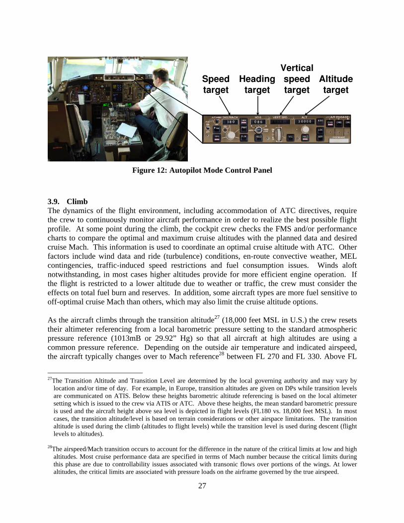
ATC commonly provides radar heading assignments (vectors) to shorten the ground track or to provide traffic spacing, which are often implemented through an autopilot Mode Control Panel (MCP) when available, as shown in Figure 12. This interface is used in many flight phases when specific altitude, heading and/or speed target values are required as communicated to the cockpit crew from ATC in order to achieve separation, sequencing or efficiency objectives. As the aircraft climbs through approximately 1500 feet above ground level (AGL), the flight attendants are notified (by a chime) that they may commence their service duties. When 10,000 feet MSL is reached, the aircraft is accelerated from 250 knots to the optimal climb speed, which can range anywhere from 270 knots to 350 knots. In addition, the flight attendants are again chimed to indicate the end of the sterile cockpit period.
26
Speedtarget
Headingtarget
Altitudetarget
Verticalspeedtarget
Figure 12: Autopilot Mode Control Panel
3.9. Climb The dynamics of the flight environment, including accommodation of ATC directives, require the crew to continuously monitor aircraft performance in order to realize the best possible flight profile. At some point during the climb, the cockpit crew checks the FMS and/or performance charts to compare the optimal and maximum cruise altitudes with the planned data and desired cruise Mach. This information is used to coordinate an optimal cruise altitude with ATC. Other factors include wind data and ride (turbulence) conditions, en-route convective weather, MEL contingencies, traffic-induced speed restrictions and fuel consumption issues. Winds aloft notwithstanding, in most cases higher altitudes provide for more efficient engine operation. If the flight is restricted to a lower altitude due to weather or traffic, the crew must consider the effects on total fuel burn and reserves. In addition, some aircraft types are more fuel sensitive to off-optimal cruise Mach than others, which may also limit the cruise altitude options. As the aircraft climbs through the transition altitude27 (18,000 feet MSL in U.S.) the crew resets their altimeter referencing from a local barometric pressure setting to the standard atmospheric pressure reference (1013mB or 29.92” Hg) so that all aircraft at high altitudes are using a common pressure reference. Depending on the outside air temperature and indicated airspeed, the aircraft typically changes over to Mach reference28 between FL 270 and FL 330. Above FL
27The Transition Altitude and Transition Level are determined by the local governing authority and may vary by
location and/or time of day. For example, in Europe, transition altitudes are given on DPs while transition levels are communicated on ATIS. Below these heights barometric altitude referencing is based on the local altimeter setting which is issued to the crew via ATIS or ATC. Above these heights, the mean standard barometric pressure is used and the aircraft height above sea level is depicted in flight levels (FL180 vs. 18,000 feet MSL). In most cases, the transition altitude/level is based on terrain considerations or other airspace limitations. The transition altitude is used during the climb (altitudes to flight levels) while the transition level is used during descent (flight levels to altitudes).
28The airspeed/Mach transition occurs to account for the difference in the nature of the critical limits at low and high
altitudes. Most cruise performance data are specified in terms of Mach number because the critical limits during this phase are due to controllability issues associated with transonic flows over portions of the wings. At lower altitudes, the critical limits are associated with pressure loads on the airframe governed by the true airspeed.
27

290, eastbound and westbound cruise levels providing for 1000 feet vertical separation are available for those aircraft that meet the equipment requirements of RVSM (Reduced Vertical Separation Minimums), otherwise 2000 feet vertical separations are required. Passenger-related activities during the climb include beginning the meal and/or beverage service, delivering any marketing PA announcements and activating any entertainment systems. In addition, the Captain usually makes a PA describing en-route flight time and weather conditions, points of interest, arrival estimate, destination weather and, if applicable, any information concerning the presence of an augmented crew. Seat belt sign usage is at the Captain’s discretion and is typically activated in the presence of adverse ride conditions, or at the flight attendants’ request such as during the meal service. The segment of the Captain’s PA which informs the passengers that “while in their seats they are to keep their seatbelts fastened” is included by many airlines as a standard procedure and a mandatory disclaimer. 3.10. Cruise As cruise altitude is reached, the power settings/Mach target are established, and the crews will report level to ATC. The crew also performs various administrative duties, including downlinking any departure delay ACARS codes and recording the engine monitor log (if not automated). The aircraft is usually equipped with at least 2 VHF transceivers and, if overwater certified, HF radios. VHF radio management usually requires one tuner to be set to the current ATC frequency, while the other is utilized for company communications or to maintain a listening watch on the universal emergency channel (121.5 MHz). If the flight extends beyond line-of-sight VHF range (oceanic and low population regions such as parts of South America), the HF units and SELCAL are used for required communications, including position reporting. Satellite communications (SATCOM) are also used where available for both ATC and company communications. SATCOM systems offer the benefit of worldwide communication coverage without the signal degradation, time-of-day variability, and other deficiencies associated with HF. In addition, when out of VHF contact with ground facilities, the crew typically maintains a listening watch on the air-to-air frequency of 123.45 MHz. This channel is used to pass along operational information such as ride reports and en-route weather directly between aircraft. During cruise, the crew must maintain a time/fuel log in order to compare planned time and fuel burn performance with the actual time of arrival (ATA) and fuel on board (FOB) over each flight plan waypoint. The baseline departure (OFF) time and take-off FOB is used to generate the ETA/EFOB (Estimated Time of Arrival/Estimated Fuel On Board) log which is usually very accurate. Consideration must be given by the cockpit crew to the possible causes of any deviations from the waypoint ETAs/EFOBs (including fuel imbalance) and the effect on the destination arrival time and fuel. Potential sources of time/burn variation include winds aloft greater or less than forecast, cruise speed or altitude different than planned or mechanical problems such as a fuel leak. The cockpit crew also continuously evaluates altitude options. As the aircraft weight decreases due to fuel burn, the optimum cruise altitude typically increases due to better engine efficiency at higher altitudes. Available altitude options may be limited by ATC, or the 2000/4000 foot vertical increments associated with the nominal airspace structure. The decision to climb must include the effects of head/tailwinds and ride conditions (icing may also be a consideration for lower cruise altitudes). Most often, the sources of information available
28

for cruise level decision making include PIREPs from other flights, ATC, the crew’s own experience, dispatch, and the flight plan. In some instances, descent to a lower cruise altitude may be preferable to take advantage of more favorable winds, better ride conditions, or in the case of a traffic issue, a more desirable cruise Mach. On international flights, transitioning through airspace boundaries under the jurisdiction of other national sovereignties may require supplementary procedures to address local restrictions. These FIR (Flight Information Region) boundaries normally require advance notification via the flight planning process (filed flight plan), and preliminary contact by the aircraft as the flight approaches the boundary. Generally, separate ATC clearances must be issued at each boundary crossing, including entering the oceanic airspace. Before entering such airspace, it is the responsibility of the crew to familiarize themselves with any specific procedural requirements including position reporting, use of datalink, VHF, or HF communications, and any other airspeed or operational limitations (holding speeds, speed limit below a given altitude, etc.). The need to deviate from the desired track due to adverse weather is always a possibility. The nature of hazardous weather en-route varies with the geographical region (e.g. transcontinental, Caribbean, North Atlantic, etc.) as well as the type of aircraft and the equipment on board. The procedures and available options for coping with adverse weather is also airspace-dependant. In the CONUS (continental U.S.), convective weather and thunderstorms often require deviations from planned routings, but this is facilitated through coordination with ATC in this VHF/radar environment. Along the North Atlantic tracks, thunderstorms are very rare, but clear air turbulence (CAT) is often present and typically requires a change of altitude to find smoother air. However, given that communication and surveillance in oceanic airspace can be much more limited (and the traffic separation requirements are consequently much larger), deviation requests are rarely granted. In the Caribbean, the presence of convective weather is made more difficult by the non-radar environment, but special deviation procedures have been instituted to allow more deviation flexibility. As in other phases of flight, the crew must be constantly prepared for the possibility of contingencies requiring diversion of the aircraft to an en-route alternate airport. In addition to the possible closure of the destination airport (due to weather, power outages, or other field situations), reasons for diverting include medical emergencies (sick passengers/crew), aircraft equipment problems, terrorist activities inflight, unacceptable holding times, fuel diversion due to wind or traffic delays. The decision to divert usually includes input from dispatch and must include a clearance from the controller – unless the Captain declares an emergency. If the situation warrants the declaration of an emergency, the flight is given priority handling en-route, and the necessary ground and rescue services are assembled to meet the aircraft upon arrival. Other, more routine duties the crew performs during cruise include monitoring the aircraft flight path and systems, maintaining lateral fuel balance within limits (if not automated), cabin temperature control, and ATC/AOC communications requirements. Operations such as flight over mountainous terrain or extended range overwater (including extended twin-engine operations, ETOPS) require special procedures to handle contingencies and emergencies in these cases due to the limited availability of alternate diversion airports. When flying over mountainous terrain, an emergency descent may be required due to a cabin pressurization
29

problem, or inability of the aircraft to maintain altitude due to an engine malfunction. In either case, escape routes must be available for all terrain-critical segments of the flight and the crew must continuously update the navigation system with decision points and acceptable alternate routes. In the case of extended overwater operations with twin-engine aircraft types, limits are placed on maximum flying time to suitable alternate airports that can be used in the event of an emergency (such as loss of an engine). For example, 180 mins ETOPS requires twin-engine aircraft to remain within 3 hours flying time of a suitable alternate (with one engine inoperative) at all times. This affects the airspace available to ETOPS aircraft (see Figure 13) and can therefore significantly alter the route flown on transoceanic flights compared to the more direct routings available to aircraft with three or four engines. In addition, ETOPS-qualified twin-jets are subject to more stringent MEL requirements compared to an equivalent non-ETOPS model. During ETOPS, alternate airports must be constantly evaluated for acceptability and, as in the case of terrain-critical situations, decision points must be established for each potential alternate.
60 mins ETOPS airspace
120 mins ETOPS airspace
180 mins ETOPS airspace Figure 13: ETOPS Airspace
3.11. Descent The descent profile is determined by both ATC limitations and optimal aircraft performance. An aircraft operating at typical cruise altitudes (31,000 to 41,000 feet) will nominally initiate the descent at 100 to 130 nautical miles from the destination airport. The distance varies primarily due to ATC restrictions/procedures but also may be influenced by equipment type and environmental conditions such as winds aloft and turbulence. The initial descent takes place with about 30 to 40 minutes remaining in the flight, at which time the crew begins their approach and landing preparations. An “In Range” message is often transmitted to the destination station either through ACARS or by VHF radio. This message includes the latest touchdown estimate, special passenger requests (wheelchairs/connections), and if not already transmitted, any maintenance discrepancies. The station transmits or uplinks the arrival gate assignment, ground
30
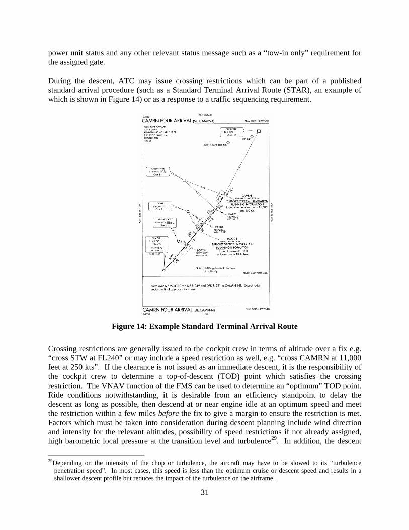
power unit status and any other relevant status message such as a “tow-in only” requirement for the assigned gate. During the descent, ATC may issue crossing restrictions which can be part of a published standard arrival procedure (such as a Standard Terminal Arrival Route (STAR), an example of which is shown in Figure 14) or as a response to a traffic sequencing requirement.
Figure 14: Example Standard Terminal Arrival Route
Crossing restrictions are generally issued to the cockpit crew in terms of altitude over a fix e.g. “cross STW at FL240” or may include a speed restriction as well, e.g. “cross CAMRN at 11,000 feet at 250 kts”. If the clearance is not issued as an immediate descent, it is the responsibility of the cockpit crew to determine a top-of-descent (TOD) point which satisfies the crossing restriction. The VNAV function of the FMS can be used to determine an “optimum” TOD point. Ride conditions notwithstanding, it is desirable from an efficiency standpoint to delay the descent as long as possible, then descend at or near engine idle at an optimum speed and meet the restriction within a few miles before the fix to give a margin to ensure the restriction is met. Factors which must be taken into consideration during descent planning include wind direction and intensity for the relevant altitudes, possibility of speed restrictions if not already assigned, high barometric local pressure at the transition level and turbulence29. In addition, the descent
29Depending on the intensity of the chop or turbulence, the aircraft may have to be slowed to its “turbulence
penetration speed”. In most cases, this speed is less than the optimum cruise or descent speed and results in a shallower descent profile but reduces the impact of the turbulence on the airframe.
31

may be shallowed by the use of anti-ice which requires higher engine idle speed, and in some older airplanes, partial power descents are required to meet cabin pressurization demands. The FMS is the primary resource available to the crew for descent planning as restrictions can be programmed directly via the CDU and a profile calculated. There are other ad hoc methods for determining the distance required to lose a given amount of altitude. The “3 to 1” rule is still used by most pilots to back up the FMS solution in which 3 miles are required for every 1000 ft of altitude loss, e.g. 30,000 feet would require 90 miles. Adjustments are then made to accommodate headwinds/tailwinds and anticipated speed restrictions (such as the 250 kts speed restriction below 10,000 feet). Destination weather and the expected approach/runway procedures are major considerations in planning the arrival. The primary source of this information is the ATIS previously described, although holding delays, weather conditions and runway operations may be passed along via ATC and/or dispatch. ATIS provides the current weather, instrument approach procedures in use, and active runways, as well as details concerning runway and taxiway closures, windshear reports, precise visibility values for individual runways, braking capability, bird activity, temporary obstructions (e.g. construction), land and hold short operations (LAHSO)30 utilisation and any other relevant safety-related information. Once the crew has received the destination weather and approach information, they begin setting up the navigation equipment for the expected arrival procedure. Of primary concern are the current weather conditions vs. the available approach procedures. Low ceilings and visibility mandate specialized procedures which in turn require specific navigation equipment necessary for executing the approaches. The baseline precision approach procedures for most well-equipped runways is the Instrument Landing System (ILS) Category I which allows landings at visibilities as low as ¼ mile and ceilings as low as 200 ft above the ground. Non-precision approaches using GPS, VOR or ADF navigation have higher minimum values. Higher precision systems and procedures can result in lower minimum Category II or even “zero/zero” conditions of Category III approaches31. If the current weather is below the minimums available for the procedure in use, or the necessary equipment is unavailable or inoperative, the crew must consider other options which include holding (if weather improvement is anticipated) or diverting to an alternate airport. Either course of action requires coordination with ATC and the airline’s dispatch office. After the crew has programmed the navigation systems and FMS for the anticipated procedure, the PF briefs the approach, using the published approach procedure as a reference. Some low visibility weather situations may mandate that the Captain always perform the PF duties to meet standardization requirements during critical low visibility operations. In addition to designating the PF, the approach briefing includes information about the required navaids, key segment and crossing altitudes, approach minimums vs. current weather, obstacles and terrain awareness, and 30During LAHSO, landing aircraft are expected stop or exit the runway before reaching a designated crossing
runway or taxiway. 31The category of operation (CAT) is determined by the current weather conditions and procedures available for the
runways in use: CAT I: RVR/visibility >= 1800 ft or ¼ mile, DH at 200 ft.; CAT II: RVR >= 1200 ft, DH at 150/100 ft; CAT IIIA: RVR >= 700 ft, DH at 50 ft; CAT IIIB: RVR as low as 300 ft, no DH. Conditions below CAT II require an autoland or HUD guidance.
32

the missed approach procedure. In most countries, the approach can be initiated (final approach segment) only if the required RVR32 or visibility requirements are satisfied. Once the approach has commenced, however, the crew need only determine that acceptable conditions exist at the missed approach point (MAP) or appropriate Decision Height (DH)33 in order to complete the approach to landing. The cabin crew activities during the descent include preparing the cabin and galleys for landing, forwarding connecting gate information to the passengers, completing customs-related documents, forwarding any cabin-related discrepancies to the cockpit and verifying that seatbelt compliance requirements are satisfied. The Captain’s descent PA announcement usually includes updates of arrival estimates and weather conditions. Any anticipated adverse weather or delays are usually briefed to both cabin crew and passengers. As the aircraft descends below the transition level (FL180 in U.S.) the altimeters are reset to the local barometric setting. The PNF works on completing the descent checklist which includes monitoring the pressurization, correcting any accumulated fuel imbalance, and calculating and/or reviewing landing data (approach speeds, runway limits). While passing through 10,000 feet, the Captain alerts the cabin crew (by chime or PA) that the sterile cockpit period is in effect and that the final cabin preparations for landing should be completed. 3.12. Terminal Area Arrival Terminal area maneuvering generally begins when the aircraft descends below 10,000 feet about 30 to 40 miles from the destination airport. At this point the flight path is defined by the STAR and/or radar vectors from ATC. Radar vectors consist of heading directives issued to the pilots and are used by ATC for the sequencing and/or spacing of air traffic. In non-radar environments, the flight is operated along established airways or feeder routes to an initial approach point defined by the approach procedure in use. In either case, the crew must keep a vigilant traffic watch and maintain terrain awareness (using electronic aids, charts, visual, etc) especially in mountainous areas and/or areas of high traffic congestion. As the flight nears the position where it will commence the approach, the crew may be issued additional real time landing information or instructions. Braking action reports are given by previous arrivals and include a qualitative ranking of the braking effectiveness during rollout after touchdown (Good, Fair, Poor, Nil in the US). Certain braking action conditions may require the utilization of specified on-board systems such as autobrakes and/or autospoilers34, or may dictate that the flight enter holding until the runway condition can be improved through plowing or chemical treatment. In low visibility conditions, real time RVR reports are issued to the arriving flights for the purpose of determining approach legality, or applying other operating 32Runway Visual Range (RVR) is a precise measurement of the horizontal visibility (in feet) for a given runway. 33The Decision Height (DH) is the height above the runway threshold from which the runway environment must be
visually acquired in order to proceed with the landing – otherwise a missed-approach is performed. 34These devices are automatically activated upon touchdown and/or wheel spin-up. Autobrakes activate the wheel
brakes so as to maintain a target deceleration selected by the flight crew. Autospoilers deploy all ground and flight spoilers in order to reduce wing lift which increases the weight on the wheels and improves braking effectiveness. The additional drag created by the raised spoilers also contributes to reducing the landing rollout.
33

restrictions to the flight (e.g. crosswind limitations, autoland requirements, etc.). ATC may also issue LAHSO instructions to arriving aircraft. The crew may refuse a LAHSO restriction (and possibly be subject to additional vectoring/sequencing), but once accepted, the restrictions must be adhered to. Microburst alerts and airspeed loss/gain reports from prior arrivals are also passed on to the crew. Adjustments may have to be made to reference landing speeds to operate under such conditions. In many cases, the flight will have to enter holding to wait out low visibility, poor braking, or windshear/microburst conditions. 3.13. Final Approach The aircraft operated by most air carriers are usually equipped to satisfy the navigation requirements of a variety of approach procedures. Precision approaches35 include Global Positioning System (GPS) autoland, GPS LNAV/VNAV and Category (CAT) I, II and III ILS approaches as previously described. Many runways at larger airports utilize the Instrument Landing System (ILS) to provide guidance to pilots during instrument conditions along a well-defined path made up of lateral and vertical elements called the localizer and glide slope respectively, as illustrated in Figure 15.
Typically
6°
Left oflocalizer
(90 Hz signaldominates)
Right oflocalizer
(150 Hz signaldominates)
3°
Typically1.4°
ILS LOCALIZER
Localizer/glide slopetransmitters
Runway
ILSGLIDE SLOPE
Above glideslope
(90 Hz signaldominates)
Below glideslope
(150 Hz signaldominates)
ILS beams typically captured
7 - 10 miles out from runway
Figure 15: Instrument Landing System
A non-precision approach is a procedure where lateral track information is provided by a local navigation aid (navaid) or satellite, but vertical guidance is received through barometric referencing or other means not directly associated with the specific runway. As expected, precision approaches provide for operations in much lower ceiling and visibility conditions.
35Precision approaches require lateral and vertical flight path information to be continuously available to the flight
crew.
34

When very low visibility conditions exist, CAT III approaches are mandated which require autoland or HUD (heads up display) guidance. Arrival delays should be anticipated during these operations due to limited spacing and runway options. When VFR conditions exist, pilots are encouraged to use all available navaids as a back-up even during visual approaches. In addition, many airfields employ instrument procedures during VFR conditions in order to manage aircraft sequencing or noise restrictions. At some point during the vectoring or feeder segment, the flight will be “cleared for the approach”. An approach clearance by ATC authorizes the crew to execute the procedures as published to the MAP/DH or landing. As mentioned earlier, it is the cockpit crew’s responsibility to determine approach legality. The current weather conditions must be compared to the procedures and equipment available, both ground-based and airborne. Downgrades in onboard automation or displays may dictate higher landing minimums and/or unavailability of certain procedures. Likewise, the inoperative status of any ground components may result in additional landing restrictions. An adverse condition of any required approach facilities is usually reported by ATC or the ATIS, but also may be detected by onboard alerting systems. Most authorities designate a specific location in the procedure where the current weather must be at or above weather minimums in order for the aircraft to continue on the approach. In the U.S., the final approach fix is designated for non-precision approaches, while glide slope intercept (at a “normal” intercept altitude) is the requirement for precision approaches. Other countries may utilize the outer marker or specific altitudes, but generally, if the flight passes the designated position with reported weather at or above minimums, it may continue to the missed approach point or decision height, as applicable. If acceptable conditions exist at the MAP/DH36 and the aircraft is stabilized or “in the slot”37, the approach may be continued to landing. If weather conditions are below minimums at the designated position, the procedure must be aborted and other alternatives considered i.e. diversion, holding, etc. Runway wind conditions must be addressed by the crew during the final approach and landing. Depending on the wind direction, intensity, and presence of gusts, adjustments may have to be made resulting in a higher planned approach speed. Maximum crosswind limitations vary among equipment type and weather conditions. The demonstrated crosswind limitations of modern transport aircraft typically range from 25 to 35 kts. This value may be further reduced by runway conditions (wet vs. dry), low visibility, or inoperative equipment (rudder malfunctions). In any event, during high crosswind situations the crew must maintain awareness of the aircraft’s limitations, as well changes in surface winds and gusts.
36In some cases, visual acquisition of the approach lighting system allows for further descent to a lower height,
however, visual contact with the runway environment must still be achieved before landing. Runway environment usually includes the runway surface and any lighting aids at or beyond the threshold.
37When an aircraft is “in the slot”, it is in a normal position for landing in stable flight. This requirement may vary
between carriers, but is typically specified as within vertical and lateral deviations from the target track, and airspeed within limits. In a more general sense, the “stabilized approach” concept adopted by most carriers requires the aircraft to be in landing configuration (on speed, gear down, flaps at landing setting) when passing through 1000 feet AGL in IMC (Instrument Meteorological Conditions) or 500 feet AGL in VMC (Visual Meteorological Conditions). Aircraft exceeding any of these parameters during the approach are expected to abort the landing and execute the published missed approach procedure.
35

Unless weather requirements dictate, use of the autopilot during the approach (or for any phase of the flight) is at the pilot’s discretion. Many carriers encourage their crews to manually operate the flight controls, when appropriate, for the purpose of maintaining proficiency. Cockpit crews are expected, however, to utilize all available information (such as the autopilot “flight director” guidance cues presented on the primary flight display) during all phases of flight including approaches and landings, whether under visual or instrument conditions. As mentioned earlier, some procedures mandate use of the autoflight system to touchdown and rollout (CAT IIIA/B), while others require autopilot disconnection before landing (non-autoland operations). It is the responsibility of the cockpit crew to determine the appropriate level of automation for a given phase of flight or procedure and to keep the resultant workload of managing the automation to a reasonable level. Unless the flight is cleared for a visual approach, ATC is responsible for aircraft and wake vortex separation. The crew, however, must be diligent in high density arrival operations involving minimum spacing between landing aircraft and can utilize on-board resources such as TCAS to supplement a diligent traffic watch by the pilots. In the event the requirements for completing the approach and landing are not satisfied, a “go-around” is executed and a standardized “missed approach procedure” and/or ATC instructions must be followed. Options available following a missed approach include entering holding to wait out whatever unacceptable condition resulted in the aborted landing, diverting to an alternate airport, or most commonly, accepting ATC vectors to initiate another approach. Many aborted landings are initiated by ATC or the cockpit crew due to traffic on the runway. In most cases a prior arrival failed to clear the runway in a timely manner, but a delayed take-off by an aircraft sitting in position at the threshold can also result in an aborted landing. If the runway is in-sight and clear when at the decision point, the cockpit crew continues the descent until initiating the landing “flare” maneuver where the descent rate is reduced just before touchdown. 3.14. Landing and Rollout After touching down on the runway, the PF uses reverse thrust, ground spoilers, and wheel braking to decelerate to taxi-speed and vacate the runway (Figure 16). In order to reduce wear on the brakes and engines, reverse thrust is utilized at higher speeds (above 60 kts.), while wheel brakes are employed at low speeds (below 100 kts). For safety and efficiency reasons, it is desirable to minimize runway occupancy during rollout and the controller expects the crews to vacate at the earliest safe opportunity38. Many airports have “high-speed turnoffs” to allow pilots to leave a runway at higher speeds than perpendicular turn-offs would allow. As the aircraft slows to turnoff speed, the Captain and First Officer assume the taxi and communications tasks as per normal ground operations. Once clear of the runway, the crew reports any adverse wind or braking conditions to the tower (in low visibility conditions the crew may also be required to report clear of the runway). After exiting the runway, the First Officer contacts
38Some high density airport operations mandate specific runway exits as part of the published arrival procedure.
36

ground control for taxi-in instructions, completes the after landing-taxi checklist and calls the local ramp control to confirm the arrival gate assignment and occupancy status.
Spoilers
Thrustreversers
Figure 16: Thrust Reverser & Ground Spoilers Deployment [photo courtesy Marinus Bergsma]
3.15. Taxi-in The pilots use taxiway charts of the destination airport to assist in the execution of taxi clearances given to them by ATC. Pilots must be diligent during ground operations at airports with which they are unfamiliar or that are undergoing construction. Airport markings and lighting, although standardized in the U.S., can be variable in other locations. Operations during nighttime or heavy precipitation also require special consideration and may substantially impede the overall traffic movement on the airfield. At some point during taxi-in the Captain determines the necessity of starting the APU. In the interest of fuel conservation, an engine may be shutdown which may require utilizing the APU, depending on the aircraft type. Normally the APU is started while the aircraft is a few minutes from the gate area, unless it has been determined that ground power will be used. In that case, the APU is not started and an engine is left running after gate arrival until the ground electric is connected by the guide crew. If the arrival gate is occupied, the aircraft may be required to wait out the delay at a remote location. Occupied gates are often the result of a delayed departure or other operational issues with the aircraft currently positioned at the gate and the anticipated delay should be passed on to ATC and the passengers. Once clearance to the gate is received, the Captain taxis to the ramp area and visually acquires the marshallers. After the crew confirms the gate area is unobstructed, the marshallers utilize lighted wands to signal clearance to taxi to the stop point adjacent to the jetbridge (Figure 17). Often delays are encountered at this point due to the unavailability of the ground crew, carts or vehicular traffic in the gate area, or a tow-in requirement for the assigned gate (in which the aircraft engines are shut down and a tug is used to tow the aircraft onto the gate position). Some stations utilize automatic parking systems which employ an arrangement of lights and/or signs that the Captain uses for lead-in line and stopping position guidance. In the absence of self-guidance, the marshaller uses wand signals to direct and stop the aircraft at the desired location. Once the brakes are parked, the agent moves the jetbridge into position at the
37

entry door, or in the case of airstair disembarkation, positions the truck(s) under the appropriate exit door(s).
Figure 17: Taxi-in Guidance
3.16. Parking In most cases, setting the parking brake and opening a cabin door trigger the “IN” event. The “IN” time is used to determine a number of metrics including the length of the flight (which is used to calculate flight crew compensation and legality for subsequent trips), FAA on-time arrival report card, customs and immigration data, and company-specific performance monitoring and scheduling adjustments. Once a source of ground power is connected (APU or external power cable), the engines are shutdown and the crew completes the engine shutdown checklist. The agent verifies the disarming of the doors with the flight attendants and opens the designated exit door(s) to commence passenger disembarkation. Usually any wheelchair passengers or unaccompanied minors are accommodated last. After engine shutdown, the ground crew begins unloading and processing the baggage and freight. The flight crew secures the cockpit and cabin before departing the aircraft. At specified outstations, an exterior post-flight walkaround inspection may be required which is completed by the cockpit crew before leaving the gate area. Post-flight inspections are not as thorough as the preflight and are usually mandated after the last flight of the day at stations with limited or contract maintenance. Finally, for international operations, any customs/immigration requirements may need to be addressed.
38

3.17. Post-flight Upon completion of postflight duties at the aircraft, the cockpit crew accomplishes any required debrief reports while the flight attendants make liquor and duty-free deposits, usually at the station operations. Debriefs/reports are required by the cockpit crew in instances of a declared emergency or ATC violation, significant mechanical failures (including engine shutdown), fuel dumping, illness, injury or death of a passenger or crew member, passenger misconduct/smoking, overweight landing, HAZMAT issues, diversions, high speed aborts, lightning strikes, near midair collisions and a number of other situations involving non-standard operations or issues. Once all cockpit and cabin obligations are fulfilled, the crew begins preparations for the next flight leg. In situations where the same aircraft is to be used, a new flight plan is pulled up and the pre-flight sequence starts all over. In most cases, however, the crew must change aircraft and relocate to the new departure gate where the planning/preflight duties are repeated. If possible, the inbound flight crew should attempt to meet the outbound flight crew and discuss any aircraft discrepancies or operational issues. If this is the last flight of the day, the crew is released from duty and typically proceeds to the crew hotel limo in cases of out of base layovers, or the bus to the employee parking lot if the inbound flight was the last leg of a sequence. If the aircraft is to be “turned around” for use in a subsequent leg, maintenance personnel will attempt to meet the flight upon gate arrival. Any discrepancies are discussed with the inbound flight crew and the necessary repairs are begun as soon as possible. If the discrepancy has been reported in in-flight, the mechanics often meet the aircraft with replacement parts such as Line Replaceable Units (LRUs) which can often allow repair in the normally-scheduled turn-around window. If the aircraft is not to be used right away, required maintenance may be performed during periods of less demand. In situations where the aircraft is finished for the day, it may be towed or taxied to a remote location, or the hangar, where the requisite maintenance and/or inspections are completed. In addition to maintenance requirements, other post-flight activity conducted by ground personnel include aircraft cleaning and de-catering, security checks and any required customs inspections. When customs or security inspections are required, delays are often incurred since the outbound crew cannot access the aircraft until the inspection is complete. In any event, it is desirable from an efficiency standpoint that ground service activities associated with the inbound flight such as catering, cleaning, and baggage handling should dovetail with the departure cycles of subsequent flight legs. 4. Summary
• Air carrier flight operations comprise a carefully choreographed sequence of tasks which must be performed in accordance with a fine-tuned schedule. These tasks, occurring both in series and parallel, demand temporal and spatial coordination and success depends on the synchronization of many different responsible parties. Flight and ground crews including cockpit and cabin personnel, dispatch, maintenance, ticketing/gate agents, guide/push crews, baggage handlers, caterers, and fuelers each must abide by specific duties and procedures to keep the operation flowing smoothly.
• Air carriers operate under a system of prioritized goals including safety, customer service, and
operating economics.
39

• Cockpit and cabin crews come from a variety of backgrounds and work experiences. An
airline may employ thousands of flight crewmembers who must function together at a high level of safety and efficiency. This can only be achieved through extensive training and adherence to well-established procedures and protocols.
• Activities before take-off include flight planning, passenger processing, aircraft preflight,
fueling, and other required ground processes. The preflight activities are orchestrated so as to achieve an “on-schedule” pushback from the departure gate, although any maintenance and gate hold issues must also be considered.
• While taxiing to the departure runway, the cockpit crew prepares the aircraft for take-off
and updates the take-off performance parameters with actual load data. In addition, any departure delays, aircraft icing, and environmental conditions such as runway contamination may need to be addressed.
• The take-off is a highly critical maneuver where a number of factors must be taken into
consideration including airport/runway, environmental, and emergency/abnormal contingencies. Departure from the terminal area, which may include route and speed restrictions, is followed by the climb to cruise altitude. The optimum cruise altitude is determined by a number of factors including efficiency, ride comfort, other traffic and/or airspace limitations. During cruise flight, the cockpit crew must continually evaluate contingency options in the event of a passenger or mechanical disruption. In addition, some flight situations require adherence to specialized procedures including international routing, mountainous terrain, and extended overwater operations.
• During descent, the crew begins preparing the cockpit and cabin for landing. In addition to
conforming to ATC restrictions, the cockpit crew plans the approach to landing which includes consideration of the destination weather, the approach procedures available, and the equipment available on the aircraft to safely and legally complete the arrival. Factors include environmental conditions (visibility, presence of convective weather, runway conditions, etc.), availability of approach aids, aircraft mechanical condition and, if necessary, available fuel for holding. In the event of an unsuccessful approach, diversion to a more suitable landing point may have to be considered.
• After landing, the aircraft is taxied to the arrival gate while the crew readies the cockpit
and cabin for parking. Once the aircraft is parked, passenger disembarkation is completed as well as baggage/cargo unloading. The flight crews proceed to the next departure gate, or to the ground transportation area if their duty day is complete.
40