mixing, placing & curing
TRANSCRIPT
AUGUST 2017 V. 39 No. 8
Mixing, Placing & Curing29 The Franklin Avenue Bridge Part 2: Analysis, design, and accelerated bridge construction
www.concreteinternational.com | Ci | AUGUST 2017 29
The Franklin Avenue BridgePart 2: Analysis, design, and accelerated bridge construction
by Dan Enser, Mario Grenville Ratnaraj, Arne P. Johnson, John S. Lawler, and Paul Backer
This is the second of a two-part series on the restoration of the Franklin Avenue Bridge in Minneapolis, MN. Part 1 focused on the rehabilitation aspects, and Part 2
focuses on the structural analysis and deck replacement using accelerated bridge construction (ABC). The engineering firms Wiss, Janney, Elstner Associates, Inc. (WJE) and HNTB Corporation worked together on the project and on these articles.
OverviewSince the historic Franklin Avenue Bridge was built in
1923, it has served as a vital link between neighborhoods in Minneapolis and St. Paul. The 1050 ft (320 m) long, five-span, open-spandrel concrete arch structure is supported on readily accessible bedrock, and it efficiently spans the Mississippi River between the high bluffs on either side.
The bridge’s original spandrels, deck, and railings were replaced during a major renovation in 1970. Degradation and changes in use led to the full replacement of the deck and spandrel cap beams during the summer of 2016. By coupling ABC techniques with prefabricated bridge elements and systems (PBES) that included cap beams, deck panels, and ornamental rail panels, the replacement of the superstructure was completed during a 116-day closure. Concrete repairs to the substructure, which were discussed in Part 1, are being completed in 2017.
Evaluation of the StructureThe HNTB Corporation team was retained in April 2013 to
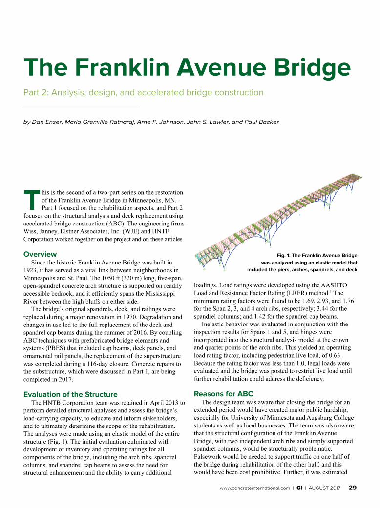
perform detailed structural analyses and assess the bridge’s load-carrying capacity, to educate and inform stakeholders, and to ultimately determine the scope of the rehabilitation. The analyses were made using an elastic model of the entire structure (Fig. 1). The initial evaluation culminated with development of inventory and operating ratings for all components of the bridge, including the arch ribs, spandrel columns, and spandrel cap beams to assess the need for structural enhancement and the ability to carry additional
loadings. Load ratings were developed using the AASHTO Load and Resistance Factor Rating (LRFR) method.1 The minimum rating factors were found to be 1.69, 2.93, and 1.76 for the Span 2, 3, and 4 arch ribs, respectively; 3.44 for the spandrel columns; and 1.42 for the spandrel cap beams.
Inelastic behavior was evaluated in conjunction with the inspection results for Spans 1 and 5, and hinges were incorporated into the structural analysis model at the crown and quarter points of the arch ribs. This yielded an operating load rating factor, including pedestrian live load, of 0.63. Because the rating factor was less than 1.0, legal loads were evaluated and the bridge was posted to restrict live load until further rehabilitation could address the deficiency.
Reasons for ABCThe design team was aware that closing the bridge for an
extended period would have created major public hardship, especially for University of Minnesota and Augsburg College students as well as local businesses. The team was also aware that the structural configuration of the Franklin Avenue Bridge, with two independent arch ribs and simply supported spandrel columns, would be structurally problematic. Falsework would be needed to support traffic on one half of the bridge during rehabilitation of the other half, and this would have been cost prohibitive. Further, it was estimated
XYXZYZ
Fig. 1: The Franklin Avenue Bridge was analyzed using an elastic model that
included the piers, arches, spandrels, and deck
30 AUGUST 2017 | Ci | www.concreteinternational.com
that construction using partial-width closure and traditional cast-in-place concrete methods would take 15 months, while construction using full closure and ABC methods would require only 4 months.
It was also estimated that the cost of user delays associated with the partial-width closure option was almost twice the cost of the 4-month closure. Contractors preferred full closure over partial closure to simplify construction, reduce risk and cost, and maintain safety of workers and the public; and the local community supported a brief full closure as opposed to a prolonged partial closure. After consideration of these factors, Hennepin County officials elected to use ABC methods during a
• Observation bays at main river Piers 2 and 3.
Improvements to the structureReduction of expansion joints—
The greatest levels of degradation were found below the failed seals of the bridge’s 15 existing expansion joints, where the underlying non-air-entrained original concrete elements were exposed to chloride-laden water. Minimization of the number of expansion joints was therefore a major goal of the new deck design, and this required radical revision of the structural connectivity of the deck and cap beams to minimize the effects of thermal expansion and contraction on the shorter spandrel columns.
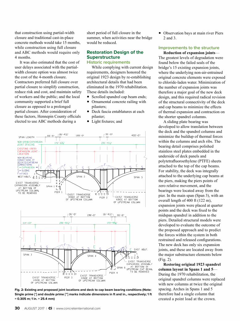
A sliding plate bearing was developed to allow translation between the deck and the spandrel columns and minimize the buildup of thermal forces within the columns and arch ribs. The bearing detail comprises polished stainless steel plates embedded in the underside of deck panels and polytetrafluoroethylene (PTFE) sheets attached to the top of the cap beams. For stability, the deck was integrally attached to the underlying cap beams at the piers, making the piers points of zero relative movement, and the bearings were located away from the pier. In the main span (Span 3), with an overall length of 400 ft (122 m), expansion joints were placed at quarter points and the deck was fixed to the midspan spandrel in addition to the piers. Detailed structural models were developed to evaluate the outcome of the proposed approach and to predict the forces within the system in both restrained and released configurations. The new deck has only six expansion joints, and these are located away from the major substructure elements below (Fig. 2).
Restoring original 1923 spandrel column layout in Spans 1 and 5—During the 1970 rehabilitation, the original spandrel columns were replaced with new columns at twice the original spacing. Arches in Spans 1 and 5 therefore had a single column that created a point load at the crown.
Fig. 2: Existing and proposed joint locations and deck to cap beam bearing conditions (Note: Single prime [ʹ] and double prime [ʺ] marks indicate dimensions in ft and in., respectively; 1 ft = 0.305 m; 1 in. = 25.4 mm)
short period of full closure in the summer, when activities near the bridge would be reduced.
Restoration Design of the Superstructure Historic requirements
While complying with current design requirements, designers honored the original 1923 design by re-establishing architectural details that had been eliminated in the 1970 rehabilitation. These details included: • Scrolled spandrel cap beam ends; • Ornamental concrete railing with
pilasters; • Deck fascia entablatures at each
pilaster; • Light fixtures; and
www.concreteinternational.com | Ci | AUGUST 2017 31
By restoring the original 1923 spandrel column layout, the loading was more uniform and the flexural demand on the arch ribs was significantly reduced, thereby restoring a load response that is closer in nature to uniform loading of the arch rib. The effort resulted in an operating load rating factor of 3.62. The contractor elected to use cast-in-place concrete to construct these columns. Spandrels were connected to the underlying arch ribs by drilling into the ribs and anchoring No. 8 reinforcing bars using epoxy adhesive.
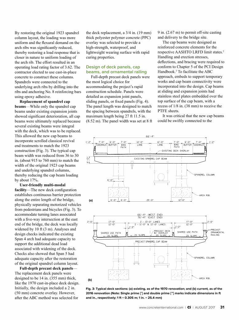
Replacement of spandrel cap beams—While only the spandrel cap beams under existing expansion joints showed significant deterioration, all cap beams were ultimately replaced because several existing beams were integral with the deck, which was to be replaced. This allowed the new cap beams to incorporate scrolled classical revival end treatments to match the 1923 construction (Fig. 3). The typical cap beam width was reduced from 36 to 30 in. (about 915 to 760 mm) to match the width of the original 1923 cap beams and underlying spandrel columns, thereby reducing the cap beam loading by about 17%.
User-friendly multi-modal facility—The new deck configuration establishes continuous barrier protection along the entire length of the bridge, physically separating motorized vehicles from pedestrians and bicycles (Fig. 3). To accommodate turning lanes associated with a five-way intersection at the east end of the bridge, the deck was locally widened by 10 ft (3 m). Analyses and design checks indicated the existing Span 4 arch had adequate capacity to support the additional dead load associated with widening of the deck. Checks also showed that Span 5 had adequate capacity after the restoration of the original spandrel column layout.
Full-depth precast deck panels—The replacement deck panels were designed to be 14 in. (355 mm) thick, like the 1970 cast-in-place deck design. Initially, the design included a 2 in. (50 mm) concrete overlay. However, after the ABC method was selected for
the deck replacement, a 3/4 in. (19 mm) thick polyester polymer concrete (PPC) overlay was selected to provide a high-strength, waterproof, and lightweight wearing surface with rapid curing properties.
Design of deck panels, cap beams, and ornamental railing
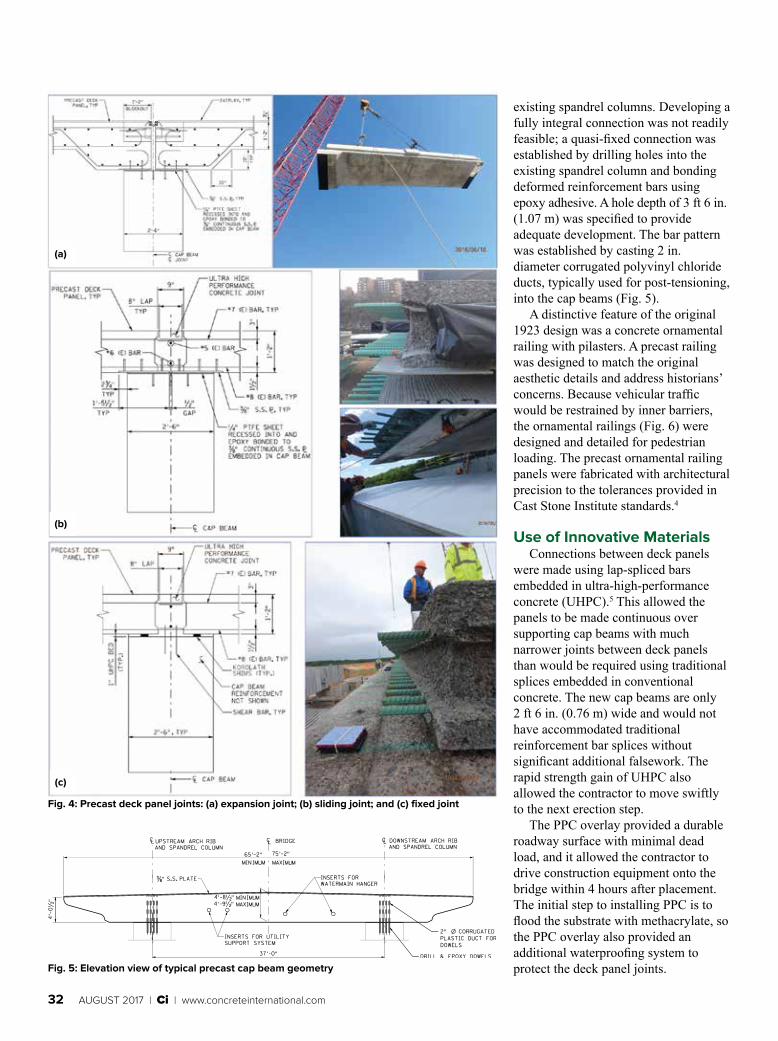
Full-depth precast deck panels were the most logical choice for accommodating the project’s rapid construction schedule. Panels were detailed as expansion joint panels, sliding panels, or fixed panels (Fig. 4). The panel length was designed to match the spacing between spandrels, with the maximum length being 27 ft 11.5 in. (8.52 m). The panel width was set at 8 ft
9 in. (2.67 m) to permit off-site casting and delivery to the bridge site.
The cap beams were designed as reinforced concrete elements for the respective AASHTO LRFD limit states.2 Handling and erection stresses, deflections, and bracing were required to conform to Chapter 5 of the PCI Design Handbook.3 To facilitate the ABC approach, embeds to support temporary works and cap beam connectivity were incorporated into the design. Cap beams at sliding and expansion joints had stainless steel plates embedded over the top surface of the cap beam, with a recess of 1/8 in. (38 mm) to receive the PTFE sheets.
It was critical that the new cap beams could be swiftly connected to the
Fig. 3: Typical deck sections: (a) existing, as of the 1970 renovation; and (b) current, as of the 2016 renovation (Note: Single prime [ʹ] and double prime [ʺ] marks indicate dimensions in ft and in., respectively; 1 ft = 0.305 m; 1 in. = 25.4 mm)
(a)
(b)
32 AUGUST 2017 | Ci | www.concreteinternational.com
Fig. 4: Precast deck panel joints: (a) expansion joint; (b) sliding joint; and (c) fixed joint
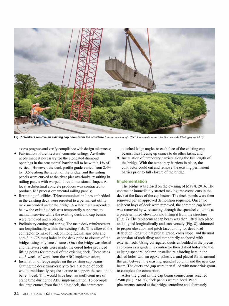
Fig. 5: Elevation view of typical precast cap beam geometry
(a)
(b)
(c)
existing spandrel columns. Developing a fully integral connection was not readily feasible; a quasi-fixed connection was established by drilling holes into the existing spandrel column and bonding deformed reinforcement bars using epoxy adhesive. A hole depth of 3 ft 6 in. (1.07 m) was specified to provide adequate development. The bar pattern was established by casting 2 in. diameter corrugated polyvinyl chloride ducts, typically used for post-tensioning, into the cap beams (Fig. 5).
A distinctive feature of the original 1923 design was a concrete ornamental railing with pilasters. A precast railing was designed to match the original aesthetic details and address historians’ concerns. Because vehicular traffic would be restrained by inner barriers, the ornamental railings (Fig. 6) were designed and detailed for pedestrian loading. The precast ornamental railing panels were fabricated with architectural precision to the tolerances provided in Cast Stone Institute standards.4
Use of Innovative MaterialsConnections between deck panels
were made using lap-spliced bars embedded in ultra-high-performance concrete (UHPC).5 This allowed the panels to be made continuous over supporting cap beams with much narrower joints between deck panels than would be required using traditional splices embedded in conventional concrete. The new cap beams are only 2 ft 6 in. (0.76 m) wide and would not have accommodated traditional reinforcement bar splices without significant additional falsework. The rapid strength gain of UHPC also allowed the contractor to move swiftly to the next erection step.
The PPC overlay provided a durable roadway surface with minimal dead load, and it allowed the contractor to drive construction equipment onto the bridge within 4 hours after placement. The initial step to installing PPC is to flood the substrate with methacrylate, so the PPC overlay also provided an additional waterproofing system to protect the deck panel joints.

www.concreteinternational.com | Ci | AUGUST 2017 33
Fig. 6: Ornamental railings were constructed using architectural precast concrete (photo courtesy of Koichiro Shimomura)
Accelerated Bridge Construction Preparation
Planning and preparatory work are critical on an ABC project. For the Franklin Avenue Bridge project, planning and preparation started a full year before the bridge was closed to
Using five casting beds and a steam curing system, the contractor produced 30 panels per week;
• Verification of existing conditions. To ensure accurate placement of the precast deck panels on the existing substructure, the bridge was surveyed to determine spandrel column geometry. The data was used to enhance the precision of the fabrication process—186 panels were shifted and 20 panels were modified to fit;
• Early production of cap beams. The precast cap beam elements were fabricated in advance of the ABC implementation;
• Pre-activity meetings and site visits. Recognizing the importance of fabrication tolerances to ensure deck panel-to-cap beam fit-up, the project team worked closely with the fabricator through pre-activity meetings and regular site visits to
traffic. ABC planning meetings included representatives from the designer, contractor, and owner teams. Preparatory work included: • Fabrication of 350 deck panels. The
contractor produced panels at a temporary casting yard about 1 mile (1.6 km) upstream of the bridge.
Concrete Craftsman Series
www.concrete.org
CCS-0(16) Concrete FundamentalsThis book is intended for anyone who wants an introduction to concrete and concrete construction, whether they are an apprentice, a journeyman, a foreman, a material supplier, or even a young engineer without field experience. Craftsmen in the concrete field may find it particularly useful as a guide for good practice.
Member: $29 / Nonmember: $49
CCS-5(16) Placing and Finishing Decorative Concrete FlatworkThe decorative concrete industry is growing fast and the standards of quality for this growing industry must be maintained and increased. This document was produced with the intent of raising the quality of education for the decorative concrete industry and supplements existing resources by providing knowledge of the materials, equipment, and techniques required to successfully install decorative concrete flatwork.
Member: $39 / Nonmember: $65
34 AUGUST 2017 | Ci | www.concreteinternational.com
assess progress and verify compliance with design tolerances; • Fabrication of architectural concrete railings. Aesthetic
needs made it necessary for the elongated diamond openings in the ornamental barrier rail to be within 1% of vertical. However, the deck profile grade varied from 2.4% to −3.5% along the length of the bridge, and the railing panels were curved at the river pier overlooks, resulting in railing panels with warped, three-dimensional shapes. A local architectural concrete producer was contracted to produce 163 precast ornamental railing panels;
• Rerouting of utilities. Telecommunication lines embedded in the existing deck were rerouted to a permanent utility rack suspended under the bridge. A water main suspended below the existing deck was temporarily supported to maintain service while the existing deck and cap beams were removed and replaced;
• Preliminary cutting and coring. The main deck reinforcement ran longitudinally within the existing slab. This allowed the contractor to make full-depth longitudinal saw cuts and core 3 in. (75 mm) holes in the deck prior to closure of the bridge, using only lane closures. Once the bridge was closed and transverse cuts were made, the cored holes provided lifting points for removal of the existing deck. These steps cut 3 weeks of work from the ABC implementation;
• Installation of ledge angles on the existing cap beams. Cutting the deck transversely to free a section of deck would traditionally require a crane to support the section to be removed. This would have been an inefficient use of crane time during the ABC implementation. To decouple the large cranes from the holding deck, the contractor
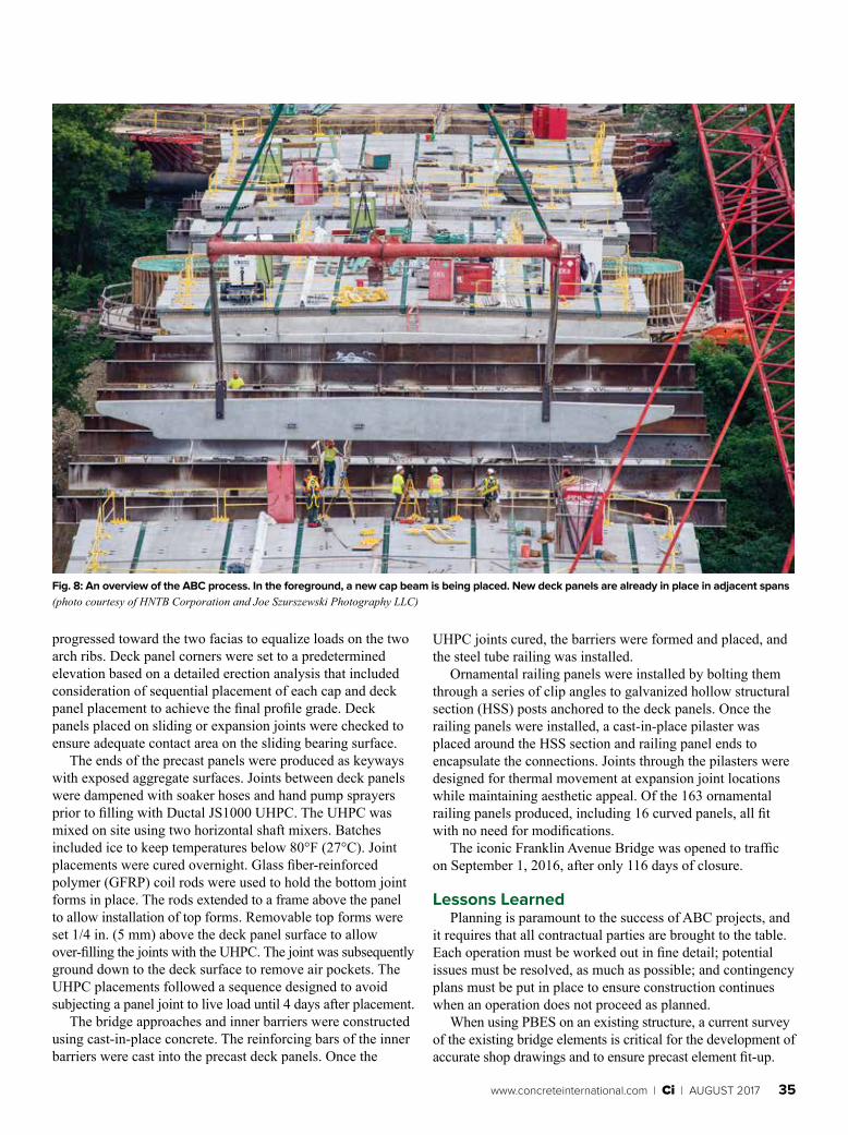
Fig. 7: Workers remove an existing cap beam from the structure (photo courtesy of HNTB Corporation and Joe Szurszewski Photography LLC)
attached ledge angles to each face of the existing cap beams, thus freeing up cranes to do other tasks; and
• Installation of temporary barriers along the full length of the bridge. With the temporary barriers in place, the contractor could cut and remove the existing permanent barrier prior to full closure of the bridge.
ImplementationThe bridge was closed on the evening of May 8, 2016. The
contractor immediately started making transverse cuts in the deck at the faces of the cap beams. The deck panels were then removed per an approved demolition sequence. Once two adjacent bays of deck were removed, the common cap beam was removed by wire sawing through the spandrel columns at a predetermined elevation and lifting it from the structure (Fig. 7). The replacement cap beam was then lifted into place and aligned longitudinally and transversely (Fig. 8); shimmed to proper elevation and pitch (accounting for dead load deflection, longitudinal profile grade, cross slope, and thermal expansion of arch ribs); and temporarily anchored with external rods. Using corrugated ducts embedded in the precast cap beam as a guide, the contractor then drilled holes into the existing spandrel column, installed reinforcing bars in the drilled holes with an epoxy adhesive, and placed forms around the gap between the existing spandrel column and the new cap beam. The ducts and gap were then filled with nonshrink grout to complete the connection.
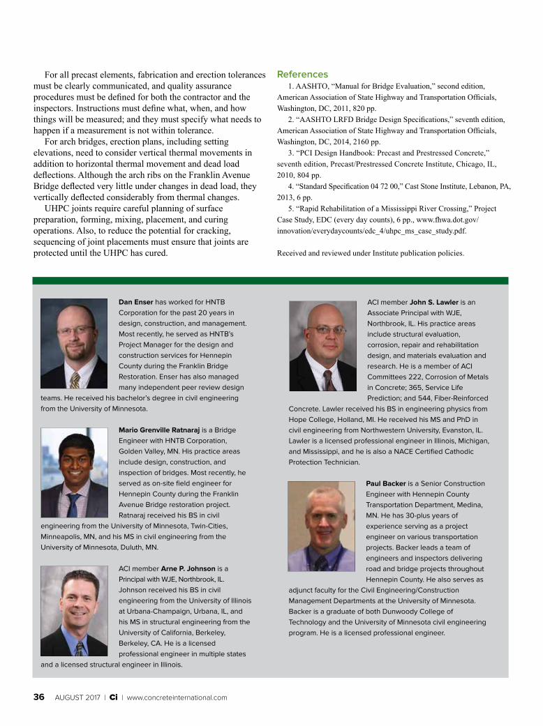
After the grout in the cap beam connections reached 2500 psi (17 MPa), deck panels were placed. Panel placements started at the bridge centerline and alternately
www.concreteinternational.com | Ci | AUGUST 2017 35
progressed toward the two facias to equalize loads on the two arch ribs. Deck panel corners were set to a predetermined elevation based on a detailed erection analysis that included consideration of sequential placement of each cap and deck panel placement to achieve the final profile grade. Deck panels placed on sliding or expansion joints were checked to ensure adequate contact area on the sliding bearing surface.
The ends of the precast panels were produced as keyways with exposed aggregate surfaces. Joints between deck panels were dampened with soaker hoses and hand pump sprayers prior to filling with Ductal JS1000 UHPC. The UHPC was mixed on site using two horizontal shaft mixers. Batches included ice to keep temperatures below 80°F (27°C). Joint placements were cured overnight. Glass fiber-reinforced polymer (GFRP) coil rods were used to hold the bottom joint forms in place. The rods extended to a frame above the panel to allow installation of top forms. Removable top forms were set 1/4 in. (5 mm) above the deck panel surface to allow over-filling the joints with the UHPC. The joint was subsequently ground down to the deck surface to remove air pockets. The UHPC placements followed a sequence designed to avoid subjecting a panel joint to live load until 4 days after placement.
The bridge approaches and inner barriers were constructed using cast-in-place concrete. The reinforcing bars of the inner barriers were cast into the precast deck panels. Once the
Fig. 8: An overview of the ABC process. In the foreground, a new cap beam is being placed. New deck panels are already in place in adjacent spans (photo courtesy of HNTB Corporation and Joe Szurszewski Photography LLC)
UHPC joints cured, the barriers were formed and placed, and the steel tube railing was installed.
Ornamental railing panels were installed by bolting them through a series of clip angles to galvanized hollow structural section (HSS) posts anchored to the deck panels. Once the railing panels were installed, a cast-in-place pilaster was placed around the HSS section and railing panel ends to encapsulate the connections. Joints through the pilasters were designed for thermal movement at expansion joint locations while maintaining aesthetic appeal. Of the 163 ornamental railing panels produced, including 16 curved panels, all fit with no need for modifications.
The iconic Franklin Avenue Bridge was opened to traffic on September 1, 2016, after only 116 days of closure.
Lessons Learned Planning is paramount to the success of ABC projects, and
it requires that all contractual parties are brought to the table. Each operation must be worked out in fine detail; potential issues must be resolved, as much as possible; and contingency plans must be put in place to ensure construction continues when an operation does not proceed as planned.
When using PBES on an existing structure, a current survey of the existing bridge elements is critical for the development of accurate shop drawings and to ensure precast element fit-up.
36 AUGUST 2017 | Ci | www.concreteinternational.com
For all precast elements, fabrication and erection tolerances must be clearly communicated, and quality assurance procedures must be defined for both the contractor and the inspectors. Instructions must define what, when, and how things will be measured; and they must specify what needs to happen if a measurement is not within tolerance.
For arch bridges, erection plans, including setting elevations, need to consider vertical thermal movements in addition to horizontal thermal movement and dead load deflections. Although the arch ribs on the Franklin Avenue Bridge deflected very little under changes in dead load, they vertically deflected considerably from thermal changes.
UHPC joints require careful planning of surface preparation, forming, mixing, placement, and curing operations. Also, to reduce the potential for cracking, sequencing of joint placements must ensure that joints are protected until the UHPC has cured.
Dan Enser has worked for HNTB Corporation for the past 20 years in design, construction, and management. Most recently, he served as HNTB’s Project Manager for the design and construction services for Hennepin County during the Franklin Bridge Restoration. Enser has also managed many independent peer review design
teams. He received his bachelor’s degree in civil engineering from the University of Minnesota.
Mario Grenville Ratnaraj is a Bridge Engineer with HNTB Corporation, Golden Valley, MN. His practice areas include design, construction, and inspection of bridges. Most recently, he served as on-site field engineer for Hennepin County during the Franklin Avenue Bridge restoration project. Ratnaraj received his BS in civil
engineering from the University of Minnesota, Twin-Cities, Minneapolis, MN, and his MS in civil engineering from the University of Minnesota, Duluth, MN.
ACI member Arne P. Johnson is a Principal with WJE, Northbrook, IL. Johnson received his BS in civil engineering from the University of Illinois at Urbana-Champaign, Urbana, IL, and his MS in structural engineering from the University of California, Berkeley, Berkeley, CA. He is a licensed professional engineer in multiple states
and a licensed structural engineer in Illinois.
ACI member John S. Lawler is an Associate Principal with WJE, Northbrook, IL. His practice areas include structural evaluation, corrosion, repair and rehabilitation design, and materials evaluation and research. He is a member of ACI Committees 222, Corrosion of Metals in Concrete; 365, Service Life Prediction; and 544, Fiber-Reinforced
Concrete. Lawler received his BS in engineering physics from Hope College, Holland, MI. He received his MS and PhD in civil engineering from Northwestern University, Evanston, IL. Lawler is a licensed professional engineer in Illinois, Michigan, and Mississippi, and he is also a NACE Certified Cathodic Protection Technician.
Paul Backer is a Senior Construction Engineer with Hennepin County Transportation Department, Medina, MN. He has 30-plus years of experience serving as a project engineer on various transportation projects. Backer leads a team of engineers and inspectors delivering road and bridge projects throughout Hennepin County. He also serves as
adjunct faculty for the Civil Engineering/Construction Management Departments at the University of Minnesota. Backer is a graduate of both Dunwoody College of Technology and the University of Minnesota civil engineering program. He is a licensed professional engineer.
References1. AASHTO, “Manual for Bridge Evaluation,” second edition,
American Association of State Highway and Transportation Officials, Washington, DC, 2011, 820 pp.
2. “AASHTO LRFD Bridge Design Specifications,” seventh edition, American Association of State Highway and Transportation Officials, Washington, DC, 2014, 2160 pp.
3. “PCI Design Handbook: Precast and Prestressed Concrete,” seventh edition, Precast/Prestressed Concrete Institute, Chicago, IL, 2010, 804 pp.
4. “Standard Specification 04 72 00,” Cast Stone Institute, Lebanon, PA, 2013, 6 pp.
5. “Rapid Rehabilitation of a Mississippi River Crossing,” Project Case Study, EDC (every day counts), 6 pp., www.fhwa.dot.gov/innovation/everydaycounts/edc_4/uhpc_ms_case_study.pdf.
Received and reviewed under Institute publication policies.