mixing valve extension module - viessmann us
TRANSCRIPT

Please file in Service Binder5774 472 - 03 04/2015
Mixing ValveExtension Module
Installation Instructionsfor use by heating contractor
Mixing Valve Extension Modulefor one heating circuit with mixing valve
Product may not be exactly as shown
Read and save these instructionsfor future reference.
IMPORTANTCertified as a component part for Viessmann boilers

Mixing Valve Extension Kit Installation
5774 4
72 -
03
Safety, Installation and Warranty Requirements
Please ensure that these instructions are read and understood before commencing installation. Failure to comply with the instructions listed below and details printed in this manual can cause product/property damage, severe personal injury, and/or loss of life. Ensure all requirements below are understood and fulfilled (including detailed information found in manual subsections).
Product documentation Read all applicable documentation before commencing installation. Store documentation near boiler in a readily accessible location for reference in the future by service personnel.
For a listing of applicable literature, please see section entitled “Important Regulatory and Safety Requirements”.
Licensed professional heating contractor The installation, adjustment, service and maintenance of this equipment must be performed by a licensed professional heating contractor.
Please see section entitled Safety and “Important Regulatory and Installation Requirements”.
Advice to owner Once the installation work is complete, the heating contractor must familiarize the system operator/ ultimate owner with all equipment, as well as safety precautions/requirements, shutdown procedure, and the need for professional service annually before the heating season begins.
Safety
Warranty Information contained in this and related product documentation must be read and followed. Failure to do so renders the warranty null and void.
2

Table of ContentsMixing Valve Extension Kit Installation
Page
3
5774 4
72 -
03
Safety
Important Precautions
General Information
Installation
Electrical Connections
Additional Information
Safety, Installation and Warranty Requirements..............2 Product documentation...........................................2 Licensed professional heating contractor...................2 Advice to owner....................................................2 Warranty...............................................................2
Important Regulatory and Installation Requirements........4 Approvals.............................................................4 Codes..................................................................4 Working on the equipment......................................4 Power supply........................................................4
About these Installation Instructions..............................5
Mounting the Extension Kit............................................6 Extension kit for installation on a wall......................6 Components..........................................................6Fitting the Supply/Return Temperature Sensor (Contact Sensor)...........................................................7 Electrical connection..............................................7
Overview of Electrical Connections...............................8.Application of Strain Reliefs - Low Voltage....................9Connecting - High Voltage...........................................9Connection of Heating Circuit Pump............................10Vitodens/Vitocrossal with Vitotronic 200.....................11Vitodens with Vitotronic 200.....................................12Vitodens 200 WB2A with Comfortol...........................13 Connecting the Vitotronic 300, Type KW3...................14Connection and Wiring Diagram..................................15Changing the Rotational Direction...............................16
Specifications..........................................................16

Mixing Valve Extension Kit Installation
5774 4
72 -
03
4
Important PrecautionsImportant Regulatory and Installation Requirements
ApprovalsViessmann boilers, burners and controls are approved for sale in North America by CSA International.
CodesThe installation of this unit shall be in accordance with local codes. In the absence of local codes, use: - CSA C22.1 Part 1 and/or local codes in Canada- National Electrical Code ANSI/NFPA 70 in the U.S.Always use latest editions of codes.The heating contractor must comply with the Standard for Controls and Safety Devices for Automatically Fired Boilers, ANSI/ASME CSD-1 where required by the authority having jurisdiction.
Working on the equipmentThe installation, adjustment, service, and maintenance of this product must be done by a licensed professional heating contractor who is qualified and experienced in the installation, service, and maintenance of hot water boilers. There are no user serviceable parts on the boiler, burner, or control.
Power supplyInstall power supply in accordance with the regulations of the authorities having jurisdiction or, in absence of such requirements, in accordance with National Codes. Viessmann recommends the installation of a disconnect switch to the 120V power supply outside of the boiler room.Ensure main power supply to equipment, the heating system, and all external controls have been deactivated. Close main oil or gas supply valve. Take precautions in both instances to avoid accidental activation of power during service work.
Please carefully read this manual prior to attempting installation. Any warranty is null and void if these instructions are not followed.
For information regarding other Viessmann System Technology componentry, please reference documentation of the respective product.
We offer frequent installation and service seminars to familiarize our partners with our products. Please inquire.
The completeness and functionality of field supplied electrical controls and components must be verified by the heating contractor. These include low water cut-offs, flow switches (if used), staging controls, pumps, motorized valves, air vents, thermostats, etc.
WARNINGTurn off electric power supply before servicing. Contact with live electric components can cause shock or loss of life.

5
5774 4
72 -
03
Mixing Valve Extension Kit Installation
About these Installation Instructions General Information
Take note of all symbols and notations intended to draw attention to potential hazards or important product information.
CAUTIONCautions draw your attention to the presence of potential hazards or important product information.
WARNINGWarnings draw your attention to the presence of potential hazards or important product information.
IMPORTANT
Indicates an imminently hazardous situation which, if not avoided, could result in death, serious injury or substantial product/property damage.
Indicates an imminently hazardous situation which, if not avoided, may result in minor injury or product / property damage.
Helpful hints for installation, operation or maintenance which pertain to the product.
This symbol indicates to note additional information
This symbol indicates that other instructions must be referenced.

Mixing Valve Extension Kit Installation
5774 4
72 -
03
6
Extension kit for installation on a wall
Components
H Mixing valve extension module
H KM BUS plug aVG x2
H Power cord pre-wired to plug fÖ
H Strap on supply temperature sensor ?
H Heating circuit pump plug sÖ
H Mixing valve actuator plug gS
H Accessory power plug fÖA
Mounting the Extension KitInstallation
1. Loosen the retaining screws from the extension kit enclosure (do not remove) .
2. Remove cover and set aside.
3. Mount the extension module enclosure to the wall using the supplied hardware.
4. Install the cover.

7
5774 4
72 -
03
Mixing Valve Extension Kit Installation
Fitting the Supply/Return Temperature Sensor (Contact Sensor)
H Fit the sensor as supply temperature sensor in the flow direction on the heating flow pipe immediately downstream of the heating circuit pump.
H When using plastic pipes, fit the sensor on any metal intermediate piece.
H Clean the supply/return pipe down to bare metal.
H Heat conducting paste is not required.
H Never thermally insulate the sensor.
Electrical connection
Insert plug ? (supply temperature sensor) or plug aJ (return temperature sensor) at the extension kit (see page 7).
Installation

Mixing Valve Extension Kit Installation
5774 4
72 -
03
8
Overview of Electrical Connections
F1 FuseS1 Rotary selector
120V~plugs 20 Heating circuit pump (on site) 40 Power supply 40A Power supply for additional controller kit for heating circuit with mixing valve (not used) 52 Mixing valve motor
Low voltage connections 2 Supply temperature sensor (included in actuator kit) 17 Return temperature sensor (optional accessory for Vitotronic 300, type KW3) 145 KM BUS
CAUTIONThe electronic modules are static sensitive. To avoid damage caused by static discharge, follow Electro-Static Discharge safety procedures.
Electrical Connections

9
5774 4
72 -
03
Mixing Valve Extension Kit Installation
Application of Strain Reliefs - Low VoltageElectrical Connections
Open the mixing valve controller cover and insert uncut strain reliefs (supplied) into all unused knock-outs.
1. Cut the strain relief to fit the cable size.
2. Insert cable through the strain relief and reconnect the cable to the plug-in connector.
3. Snap the strain relief into an open knock-out.
4. Insert the plug-in connector into the corresponding socket.
Connecting - High Voltage
1. Route high voltage cable through knockouts provided and apply proper strain relief.

Mixing Valve Extension Kit Installation
5774 4
72 -
03
10
Connecting the Heating Circuit Pump
Specification of the heating circuit pump 120V~
Rated current: >1A
Specification of the contactor:Rated voltage: 120VRated current: 1A
Heating circuit pump 120V~
LegendA Heating circuit pumpB Contactor/RelayC Power supply with disconnect and protectionsÖ To the extension kit
Heating circuit pump 208/460/575V~
Specification of the heating circuit pump 208/460/575V~
Specification switching the contactor:
Rated voltage 120V~Rated current 1A
Electrical Connections
LegendA Heating circuit pumpB Contactor/RelayC Power supply with disconnect and protectionsÖ To the extension kit
Note: In underfloor heating circuits, integrate a temperature limiter on site for limiting the maximum temperature of underfloor heating systems.
Specification of the heating circuit pump 240V~
Specification of the contactor:Rated voltage: 120VRated current: 1A
Heating circuit pump 240V~
LegendA Heating circuit pumpB Contactor/RelayC Power supply with disconnect and protectionsÖ To the extension kit

11
5774 4
72 -
03
Mixing Valve Extension Kit Installation
Vitodens/Vitocrossal with Vitotronic 200 Type H01BElectrical Connections
The extension kit can be connected to the following appliances:
H Vitodens 200-W – Type B2HA/B2HB
H Vitodens 222-F – Type B2TA/B2TB
H Vitocrossal 300 CU3A
WARNINGIncorrect core termination can cause severe injuries and damage to the equipment.Never interchange cores “L” and “N”.
The mixing valve controller kit can only be used with the listed gas-fired hot water heating boilers listed above and a weather-responsive control.
For details on coding and connection to the control, please refer to the relevant boiler Start-up/Service Instructions.
A Mixing valve controller: 40 Power supply 145 KM BUS S1 Rotary selector: for position, see the table below 145 KM BUS to the control unit or to the KM BUS distributor (accessories)B Vitotronic 200: KM BUS screw at terminals of the EA1 module, pre- installed in the boiler electrical connection box or 145 KM BUS to the control unit or to the KM BUS distributor (accessories)
C 120V receptacle
IMPORTANTThe receptacle must have a 15A overcurrent protection.
Rotary selector settings
Heating circuit that the mixing valve affects
Connected sensors Rotary selector position
Heating circuit with mixing valve, M2
Supply temperature sensor
‘2’ (factory set)
Heating circuit with mixing valve, M3
Supply temperature sensor
‘4’
Mixing Valve Extension Kit Installation
5774 4
72 -
03
12
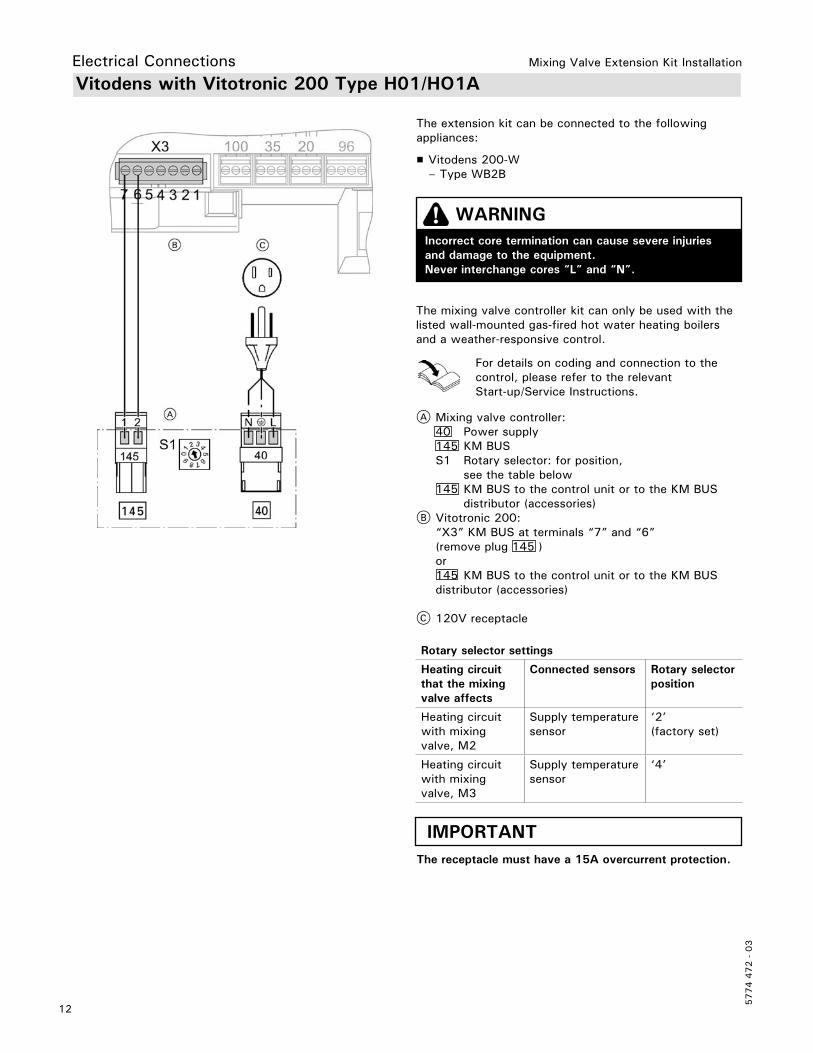
Vitodens with Vitotronic 200 Type H01/HO1A
The extension kit can be connected to the following appliances:
H Vitodens 200-W – Type WB2B
WARNINGIncorrect core termination can cause severe injuries and damage to the equipment.Never interchange cores “L” and “N”.
Electrical Connections
The mixing valve controller kit can only be used with the listed wall-mounted gas-fired hot water heating boilers and a weather-responsive control.
For details on coding and connection to the control, please refer to the relevant Start-up/Service Instructions.
A Mixing valve controller: 40 Power supply 145 KM BUS S1 Rotary selector: for position, see the table below 145 KM BUS to the control unit or to the KM BUS distributor (accessories)B Vitotronic 200: “X3” KM BUS at terminals “7” and “6” (remove plug 145 ) or 145 KM BUS to the control unit or to the KM BUS distributor (accessories)
C 120V receptacle
IMPORTANTThe receptacle must have a 15A overcurrent protection.
Rotary selector settings
Heating circuit that the mixing valve affects
Connected sensors Rotary selector position
Heating circuit with mixing valve, M2
Supply temperature sensor
‘2’ (factory set)
Heating circuit with mixing valve, M3
Supply temperature sensor
‘4’

13
5774 4
72 -
03
Mixing Valve Extension Kit Installation
A Mixing valve controller: 40 Power supply 145 KM BUS S1 Rotary selector: for position, see the table below 145 KM BUS to the control unit or to the KM BUS distributor (accessories)
B Control unit: “X5” KM BUS at terminals “3” and “4” (remove plug 145 ) or With plug 145 to the KM BUS distributor (accessories)
C 120V receptacle
Vitodens 200 WB2A with Comfortrol
WARNINGIncorrect core termination can cause severe injuries and damage to the equipment.Never interchange cores “L” and “N”.
IMPORTANTThe receptacle must have a 15A overcurrent protection.
Electrical Connections
Rotary selector settings
Heating circuit that the mixing valve affects
Connected sensors Rotary selector position
Heating circuit with mixing valve, M2
Supply temperature sensor
‘2’ (factory set)
Heating circuit with mixing valve, M3
Supply temperature sensor
‘4’

Mixing Valve Extension Kit Installation
5774 4
72 -
03
14
Connecting the Vitotronic 300, Type KW3
WARNINGIncorrect core termination can cause severe injuries and damage to the equipment.Never interchange cores “L” and “N”.
Electrical Connections
Rotary selector settings
Heating circuit that the mixing valve affects
Connected sensors Rotary selector position
Heating circuit with mixing valve, M2
Supply temperature sensor
‘2’ (factory set)
Supply temperature sensor and return temperature sensor
‘3’
Heating circuit with mixing valve, M3
Supply temperature sensor
‘4’
Supply temperature sensor and return temperature sensor
‘5’
A Mixing valve controller 40 Power supply 145 KM BUS S1 Rotary selector: for position, see the table below 145 KM BUS to the control unit or to the KM BUS distributor (accessories)B Vitotronic 300 type KW3 C 120V receptacle
IMPORTANTThe receptacle must have a 15A overcurrent protection.

15
5774 4
72 -
03
Mixing Valve Extension Kit Installation
Connection and Wiring Diagram
LegendA1 Main PCBF1 FuseS1 Rotary selector
120V~plugs 20 Heating circuit pump (on site) 40 Power supply 120V 60Hz 40A Power supply for additional controller for heating circuit with mixing valve (not used) 52 Mixing valve actuator
Low voltage connections2 Supply temperature sensor17 Return temperature sensor (optional accessory for Vitotronic 300, type KW3)145 KM BUS
Electrical Connections

Tec
hnic
al in
form
atio
n su
bjec
t to
cha
nge
witho
ut n
otic
e.Pr
inte
d on
env
ironm
enta
lly f
riend
ly
(rec
ycle
d an
d re
cycl
able
) pa
per.
Mixing Valve Extension Kit Installation
5774 4
72 -
03
Changing the Rotational Direction
LegendHR Heating returnHV Heating flowKR Boiler returnKV Boiler flow
Change the rotational direction in the following cases:
H On systems with Modular-Divicon.
H For the following installation examples:
1. Switch OFF the power supply to the control unit.
2. Remove the casing cover of the extension kit.
3.
Interchange wires RD and BK at plug gS to change the rotational direction.
4. Connect the extension kit.
5. Check the rotational direction.
Note: If a fault occurs during commissioning, check the mixing valve installation (see mixing valve installation instructions).
Specifications
Rated voltage 120V~Rated frequency 60 HzRated current 2APower consumption
H Wall mounting 1.5 W
Permissible ambient temperature
H During operation 32 to 104°F (0 to 40°C)
H During storage and transport -4 to 149°F (–20 to 65°C)
Rated relay output breaking capacity
H Heating circuit pump sÖ 1A 120V~
H Mixing valve motor 0.2A 120V~
Curve, supply/return temperature sensor
Temperature
Res
ista
nce
in K