ml600_user_manual_6-apr-09.pdf
TRANSCRIPT

User Manual
ML600 Release R6.1
Revision No. A02
Document No. 520R60621E


ML600 User Manual i
Preface Material
Document Identification ML600 Release 6.1 Document No. 520R60621E Revision No. A02 Date: APR 2009
Copyright Copyright © 2009 Actelis Networks, Inc. All rights reserved. Printed in U.S.A.
This publication is protected by International copyright law. No part of this publication may be copied or distributed, transmitted, transcribed, stored in a retrieval system, or translated into any human or computer language in any form or by any means, electronic, mechanical, magnetic, manual or otherwise, or disclosed to third parties without the express written permission of Actelis Networks, Inc., 6150 Stevenson Boulevard, Fremont, CA 94538.
Disclaimer of Warranties and limitation of Liabilities Actelis Networks, Inc. (hereafter referred to as Actelis Networks, Inc. or Actelis Networks), makes no representation or warranties with respect to the contents hereof and specifically disclaims any implied warranties of merchantability or fitness for a particular purpose. Further, in no event, shall Actelis Networks be liable for incidental or consequential damages in connection with or arising from the use of the ML600 series, cards and modules, accessories kits, this manual or any related materials. Actelis Networks reserves the right to revise this publication from time to time and to make changes in the content hereof without obligation to notify any person of such revisions or changes.
Trademarks Actelis, Actelis Networks, EFMplus, Carrier Ethernet over Copper and related logos and icons are the registered trademarks or copyrights of Actelis Networks. Other identifiers may be trademarks or marks of their respective owners.
Patent protection The products described in this document are protected by U.S. Patent No. 6,744,811 and other U.S. patents, foreign patents, and/or pending applications.

Preface Material
ii User Manual ML600
Document Objectives This manual provides a general description of the ML600 device, detailed instructions for the deployment and maintenance of the ML600 device.
Intended Audience The intended audience for this document is both technical and non-technical staff within Network Service Provider (NSP) organizations, and it is assumed that the reader has a general understanding of voice and data communications, the xDSL industry and high-speed digital services.
Symbols Used in this Manual
Warning: Indicates information on how to avoid personal injury.
Caution: Indicates information on how to avoid damage to the equipment or to avoid possible service disruption.
ESD: Indicates information on how to avoid discharge of static electricity and subsequent damage to the Actelis system.
Actelis supplies each product with the following system documentation and applications, (for Documentation and Software Applications ordering contact Customer Support):
• ML User Manual - provides a general description, detailed instructions for the deployment, configuration and maintenance of the product. The User Manual is available in PDF format and as Online Help. A hard copy can be ordered separately.
• ML Quick Installation Guide - provides summary explanations of the procedures for installing the Actelis system. The Quick Installation Guide is included in each Actelis product package and also can be ordered separately.
• MetaASSIST View - software and MetaASSIST View documentation. MetaASSIST view installation files are available both for Windows (*.exe) and Unix (*.bin). The two files are also available with *.mft extension. These files can be stored on and downloaded from the ML device as explained in Updating Software Versions (on page 12-12).
Contact Information Please contact your local sales representative, service representative or distributor directly for any help needed. For additional information concerning warranty, sales, service, repair, installation, documentation, training or distributor locations, use any one of the following:
• Internet: Visit the Actelis Networks World Wide Web site http://www.Actelis.com

Preface Material
ML600 User Manual iii
• Mail to: Actelis Networks customer support Mailto: [email protected] for technical support.
• Customer support: Contact Actelis Networks Customer Support directly at one of the following numbers:
• Belgium: (0) 800 71180
• Denmark: 80 887 771
• France: (0) 800 918 450
• Germany: (0) 800 1833504
• Netherlands: (0) 800 0225982
• UK: (0) 800 9179049
• USA: +1 866 638 2544 or +1 510 545 1071
For all other inquiries, please call +1 866 ACTELIS (+1 866 228 3547) or +1 510 545 1071.
Document Feedback We welcome your comments and suggestions about this document. Please mail them to Technical Publications, Actelis Networks, 6150 Stevenson Boulevard, Fremont, CA 94538 or to [email protected] mailto:[email protected]. Include the document number, revision number and title of this document in your correspondence. Please include your name and phone number if you are willing to provide additional clarification.

ML600 Certification
iv User Manual ML600
ML600 Certification
FCC Class B Compliance ML600 series complies with the limits for a Class B digital device, pursuant to part 15 of the FCC rules.
These limits are designed to provide reasonable protection against harmful interference when the equipment is operated in a residential environment notwithstanding use in commercial, business and industrial environments. This equipment generates, uses, and can radiate radio-frequency energy and, if not installed and used in accordance with this Online Help may cause harmful interference to radio communications.
The authority to operate this equipment is conditioned by the requirement that no modifications will be made to the equipment unless the changes or modifications are expressly approved by Actelis Networks, Inc.
Canadian Emissions Requirements This Class B digital apparatus meets all requirements of the Canadian Interference-Causing Equipment Regulations.
Cet appareil numérique de la classe B respecte toutes les exigences du Règlement sur le matériel brouilleur du Canada.
CE Mark This equipment complies with the Council Directive 89/336/EEC for electromagnetic compatibility. Conformity with this directive is based upon compliance with the following harmonized standard ETSI EN 300 386 V1.3.1 (2001- 09).
MEF Certification The ML device has undergone testing in accordance with MEF 14 requirements and found to comply with certain requirements detailed in the Iometrix detailed test report.

General Safety Instructions
ML600 User Manual v
General Safety Instructions Résumé des conditions générales de sécurité 1. Read and follow all warning notices and instructions marked on this product or included
in this manual. Lisez et suivez attentivement les notes d'avertissements et les instructions indiquées sur ce produit ou inclues dans ce manuel.
2. All installation, repair or replacement procedures must be performed by qualified service personnel. Toute installation, procédure d'entretien ou de remplacement doit être effectuée par un personnel de service qualifié.
3. Before attempting to operate or repair this product, make sure product is properly grounded. Avant d'essayer de faire fonctionner ou de réparer ce produit, veillez à ce que le produit soit connexion de mis à la terre correctement.
4. This product uses an external power source. Do not touch exposed connections, components or wiring when power is present. Ce produit utilise une source de courant externe. Veuillez ne pas toucher les connections, éléments ou fils électriques découverts quand il y a du courant.
5. Do not operate this product with panels removed or with suspected failure or damage to electrical components. Ne faites pas fonctionner ce produit sans ses panneaux ou si vous suspectez une défaillance ou un dégât au niveau des composants électriques.
6. Do not operate or repair this product in wet or damp conditions or in an explosive atmosphere. Ne faites pas fonctionner ce produit dans des conditions mouillées ou humides ou dans une situation où il y a risque d'explosion.
7. Keep product surfaces clean and dry Gardez les surfaces du produit propres et sèches.
8. Provide proper ventilation. Fournissez une aération appropriée.
9. Observe all ratings and markings on the product. Use only the fuse type and rating specified for this product. Before making connections to the product, consult the appropriate chapters of this manual for further ratings information. Observez toutes les valeurs nominales et indications sur le produit. Utilisez uniquement le genre de fusible spécifié pour ce produit. Avant d'établir des connexions au produit, consultez les chapitres du manuel pour obtenir plus d'informations sur les évaluations.

General Safety Instructions
vi User Manual ML600
10. Many of the cables for this product are supplied by Actelis Networks. Cables that are supplied by the customer must comply with the regulatory inspection authorities and are the responsibility of the customer. To reduce the risk of fire, make sure all cables are UL Listed or CSA Certified. De nombreux câbles de ce produit sont fournis par la société Actelis Networks. Les câbles qui sont fournis par le client doivent adhérer aux normes des autorités d'inspection et relèvent de la responsabilité du client. Pour diminuer le risque d'incendie, assurez vous que les câbles soient sur la liste UL ou certifiés CSA.
11. This equipment must be installed according to country national electrical codes. For North America, equipment must be installed in accordance with the US National Electrical Code, Articles 110–16, 110–17 and 110–18 and the Canadian Electrical Code, Section 12. If necessary, consult with the appropriate regulatory agencies and inspection authorities to ensure compliance. Cet équipement doit être installé en fonction des codes d'électricité du pays. En Amérique du Nord, l'équipement doit être installé suivant le Code National d'Electricité Américain, Articles 110-16, 110-17 et 110-18 et suivant le Code d'Electricité Canadien, Section 12. Si nécessaire, consultez les organismes de réglementation et les autorités d'inspection appropriés pour vous assurer de la conformité de l'installation.
12. Overcurrent Protection: It is recommended to incorporate in the building wiring, a readily accessible Listed branch circuit overcurrent protective device rated 2A minimum - 5A maximum. A 5A circuit over current protective device can feed two ML600 units in rack mount sleeve. Protection en cas de courant excessif: nous recommandons d'ajouter un appareil de protection 2A min. - 5A max., facilement accessible dans le circuit électrique de l'immeuble. Un appareil de protection à circuit 5A peut alimenter 2 unités ML600 placés l'un sur l'autre en étagères.
13. The equipment shall be connected to a properly earthed supply system. L'équipement doit être connecté à un système d'alimentation mis à la terre correctement.
14. All equipment in the immediate vicinity shall be earthed the same way and shall not be earthed elsewhere. Tout équipement à proximité immédiate doit avoir la même mise à la terre et ne doit pas avoir une mise à la terre ailleurs.
15. A disconnect device is not allowed in the earthed circuit between the DC supply source and the frame/earthed circuit connection. Ne placez pas u à la tern appareil déconnecté dans le circuit mis à la terre entre la source d'alimentation DC et la connexion au circuit misre.
16. In case of FAN alarm, it is required to replace ML600 within four (4) hours. Dans le cas d'une alarme FAN, vous devez remplacer le ML600 dans les 4 heures qui suivent.

ML600 User Manual vii
Contents Preface Material............................................................................................................................................1 ML600 Certification .....................................................................................................................................4 General Safety Instructions...........................................................................................................................5
1 Introduction 1-1 About ML600 ........................................................................................................................................... 1-2
ML600 Architecture ...................................................................................................................... 1-4 Deployment Topologies............................................................................................................................ 1-5
ML600 Point-to-Point ................................................................................................................... 1-6 ML600 Point-to-Point via Repeaters ............................................................................................. 1-6 ML600 in Point-to-Multipoint....................................................................................................... 1-9 ML688 Point-to-Dual Point......................................................................................................... 1-10 ML688 Drop-and-Continue......................................................................................................... 1-11
About ML650 ......................................................................................................................................... 1-12 ML650 Architecture .................................................................................................................... 1-12 ML650 Topologies ...................................................................................................................... 1-13
Management Applications ...................................................................................................................... 1-14
2 Getting Started 2-1 Front and Rear Panel Descriptions ........................................................................................................... 2-2
ML600 Front Panel Description .................................................................................................... 2-2 ML600 Rear Panel Description ..................................................................................................... 2-3
Connecting to and Navigating the MetaASSIST View............................................................................. 2-5 Craft Connection to the ML........................................................................................................... 2-6 TCP/IP Connection to the ML....................................................................................................... 2-8 Auto-discovery of ML Systems................................................................................................... 2-10 ML link Visibility via MetaASSIST............................................................................................ 2-12 ML50/ML600 Failed to Connect................................................................................................. 2-14
ML600 Commissioning Procedures ....................................................................................................... 2-16 Initial Setup Procedure (Wizard) ................................................................................................. 2-16 Service Configuration Wizard ..................................................................................................... 2-17 Step-by-Step Commissioning Procedures ................................................................................... 2-18
3 Management Configuration 3-1 NE Management Communication Protocols............................................................................................. 3-2 Craft Port Configuration ........................................................................................................................... 3-3 IP/LAN Connectivity on Directly Connected NE..................................................................................... 3-4
L2 (MGMT VLAN) Connectivity ................................................................................................. 3-4 L3 (IP) Connectivity...................................................................................................................... 3-5
IP/LAN Connectivity on Indirectly Connected NE .................................................................................. 3-7 L2 (MGMT VLAN) and L3 (IP) Connectivity.............................................................................. 3-7
MetaASSIST View Workplace................................................................................................................. 3-9 Menu Bar..................................................................................................................................... 3-10

Contents
viii ML600 User Manual
Physical Tab ................................................................................................................................ 3-12 Connectivity Tab ......................................................................................................................... 3-14 Current Alarms Area ................................................................................................................... 3-15 Performing Group Operations ..................................................................................................... 3-16 Multi-lingual Support .................................................................................................................. 3-17
SNMP Agent and Trap Parameters......................................................................................................... 3-18 SNMP Agent Configuration ........................................................................................................ 3-18 SNMP Trap Destinations............................................................................................................. 3-20 SNMP Trap Filtering................................................................................................................... 3-21
System Name Configuration................................................................................................................... 3-22 System Time and Date............................................................................................................................ 3-23
Configuring Date and Time Manually......................................................................................... 3-23 Automatic Date and Time Adjustment ........................................................................................ 3-24 Daylight Saving Time (DST) Configuration ............................................................................... 3-25
4 Equipment and Port Configuration 4-1 System Configurable Attributes................................................................................................................ 4-2 Alarms and Indications Control ................................................................................................................ 4-4
General Purpose Output (GPO) Configuration.............................................................................. 4-4 Environmental Alarm (GPI) Configuration................................................................................... 4-6
Pluggable Equipment (SFP) Control ........................................................................................................ 4-9 SFP Module Automatic Control .................................................................................................... 4-9 SFP Module Manual Control....................................................................................................... 4-10
PFU-8 Configuration .............................................................................................................................. 4-11 ML650 - DSx1, clock and CES Configuration ....................................................................................... 4-12
Configuring DSx1 Type and CES Parameters............................................................................. 4-12 Configuring DSx1 Ports .............................................................................................................. 4-15 Configuring the Clock Source ..................................................................................................... 4-18
Modem Line Ports (MLP) Configuration ............................................................................................... 4-21 Maximum Rate Limits................................................................................................................. 4-23
HSL Configuration ................................................................................................................................. 4-24 HSL Configuration ...................................................................................................................... 4-24 HSL Calibration........................................................................................................................... 4-28 Bandwidth Restoration Configuration......................................................................................... 4-32 DSS Profile.................................................................................................................................. 4-36 Custom Spectral Mode ................................................................................................................ 4-37
Ethernet Port Configuration.................................................................................................................... 4-39 Configuring Ethernet Ports.......................................................................................................... 4-39 Isolated Port in ML688 Devices .................................................................................................. 4-44 LLCF in ML600 Devices ............................................................................................................ 4-45 Rate Limit Configuration............................................................................................................. 4-50
Static Link Aggregation (LAG) Configuration....................................................................................... 4-52 Overview of the LAG Configuration Procedure.......................................................................... 4-52 Configuration Considerations...................................................................................................... 4-53 Enabling LAGs and Configuring LAGs ...................................................................................... 4-53 Allocating Ethernet Ports to LAGs.............................................................................................. 4-55
5 Ethernet Bridge and STP/RSTP Configuration 5-1 Ethernet Bridge Configuration.................................................................................................................. 5-2
IEEE 802.1 Switching Principles .................................................................................................. 5-3

Contents
ML600 User Manual ix
Configuring ML600 Ethernet Bridge ............................................................................................ 5-3 LLDP Configuration...................................................................................................................... 5-7 Quality of Service (QOS) .............................................................................................................. 5-8
STP/RSTP and Provider Bridge Configuration ...................................................................................... 5-20 STP/RSTP Principles................................................................................................................... 5-21 STP/RSTP in ML Systems .......................................................................................................... 5-22 STP/RSTP Bridge Configuration ................................................................................................ 5-23 STP/RSTP Ports Configuration ................................................................................................... 5-24
6 Ethernet Service Configuration 6-1 Service Configuration Procedure.............................................................................................................. 6-2 Service Configuration Details................................................................................................................... 6-3
7 VLAN Configuration 7-1 VLAN Configuration Principles ............................................................................................................... 7-2 Membership Principles ............................................................................................................................. 7-3
VLAN Membership Forms............................................................................................................ 7-3 VLAN Membership Rules............................................................................................................. 7-6
Management VLAN Configuration .......................................................................................................... 7-9 Traffic VLAN Configuration.................................................................................................................. 7-11 VLAN Topologies .................................................................................................................................. 7-13
Symmetric Topologies................................................................................................................. 7-14 Asymmetric Topologies .............................................................................................................. 7-21
8 L2CP Processing 8-1 Supported L2CP Protocols........................................................................................................................ 8-2 Configuring Handling of L2CP Frames.................................................................................................... 8-3 Deployment Considerations...................................................................................................................... 8-6
9 EVC Configuration 9-1 Introducing MEF Terminology................................................................................................................. 9-2 MEF10 QoS flow Overview ..................................................................................................................... 9-4 Defining EVCs.......................................................................................................................................... 9-5 Associating VLANs with EVC................................................................................................................. 9-6 BW Profile Definition............................................................................................................................... 9-7 EVC Services Definition .......................................................................................................................... 9-9 Identification Rules Definition ............................................................................................................... 9-12
Calculating the Range Covered by a Rule ................................................................................... 9-16 Deployment Considerations.................................................................................................................... 9-19
10 Ethernet CFM Configuration 10-1 About the CFM Infrastructure ................................................................................................................ 10-2
CFM Domains ............................................................................................................................. 10-3 CFM MIP .................................................................................................................................... 10-3 CFM MA ..................................................................................................................................... 10-3 CFM MEP ................................................................................................................................... 10-4

Contents
x ML600 User Manual
CFM Messages in ML Systems................................................................................................... 10-4 CFM on ML NE .......................................................................................................................... 10-5
Ethernet CFM Configuration Procedure................................................................................................. 10-7 Ethernet CFM Configuration Window ........................................................................................ 10-7 Defining a CFM Domain............................................................................................................. 10-9 Defining Domain MIPs ............................................................................................................. 10-11 Defining CFM Maintenance Associations................................................................................. 10-13 Defining MEPs .......................................................................................................................... 10-15
11 Security Management 11-1 Managing User Accounts........................................................................................................................ 11-2
The User Accounts Pane.............................................................................................................. 11-3 Default User Accounts................................................................................................................. 11-4 Adding a User Account ............................................................................................................... 11-5 Editing User Account .................................................................................................................. 11-6 Deleting a User Account.............................................................................................................. 11-6
Password Control.................................................................................................................................... 11-7 System Wide User Settings ......................................................................................................... 11-7 Editing Password in Session........................................................................................................ 11-9
Locking Out Users................................................................................................................................ 11-10 Lock a User Account ................................................................................................................. 11-10 System Wide Lockout Behavior................................................................................................ 11-10
Managing Sessions ............................................................................................................................... 11-12 User Session Information .......................................................................................................... 11-12 Viewing and Managing Current Logged in Sessions ................................................................ 11-12
RADIUS ............................................................................................................................................... 11-15 Configuring for RADIUS Operation ......................................................................................... 11-15 Configuring RADIUS on ML.................................................................................................... 11-16 RADIUS Message Parameters Supported by ML ..................................................................... 11-18 RADIUS Service Type Parameters Supported by ML .............................................................. 11-20
IP Access Control ................................................................................................................................. 11-21 Viewing IP Access Control List ................................................................................................ 11-21 Adding a Client IP Address to the Access Control List............................................................. 11-23 Configuring the IP Access Control State................................................................................... 11-23 Editing the IP Access Control List ............................................................................................ 11-24 Deleting a Client........................................................................................................................ 11-24
SSH - Secure Shell................................................................................................................................ 11-25 Managing SSH Communication................................................................................................ 11-26 Generating SSH Client Key....................................................................................................... 11-27 SSH Server Overview................................................................................................................ 11-28 Generating SSH Server Key ...................................................................................................... 11-29 SSH Server/Client Authentication............................................................................................. 11-30 Enable Authentication Control on SSH Server.......................................................................... 11-36
12 Administration 12-1 Using MetaASSIST View....................................................................................................................... 12-2
Configuration Backup and Restore.............................................................................................. 12-2 Log Files Management ................................................................................................................ 12-5 ML Software Control ................................................................................................................ 12-12 Repeaters SW Control via ML NE ............................................................................................ 12-22

Contents
ML600 User Manual xi
Restarting the ML NE ............................................................................................................... 12-28 Using Web Browser.............................................................................................................................. 12-29
Accessing and Navigating the Support Page ............................................................................. 12-29 Configuration Backup and Restore............................................................................................ 12-31 Retrieving Logs ......................................................................................................................... 12-34 Retrieving Files ......................................................................................................................... 12-34 ML Software Control ................................................................................................................ 12-35 Repeaters SW Control via Web Browser .................................................................................. 12-37 Displaying the TL1 Document .................................................................................................. 12-37
13 Monitoring 13-1 Monitoring and Managing Alarms.......................................................................................................... 13-2
Alarms Pane View....................................................................................................................... 13-4 Alarm Icons and Color Map ........................................................................................................ 13-5 Alarm Information in Summary Tables....................................................................................... 13-5 Configuring Fault Notification Sound Effects............................................................................. 13-8 Managing Element Specific Alarms............................................................................................ 13-9
System Status Monitoring..................................................................................................................... 13-11 Network Element Monitoring.................................................................................................... 13-11 System ....................................................................................................................................... 13-12 Equipment Inventory and Status Monitoring............................................................................. 13-13
Ethernet Bridge Monitoring.................................................................................................................. 13-19 MAC Forwarding Database Monitoring.................................................................................... 13-20 STP Bridge Status Monitoring .................................................................................................. 13-21 STP Ports Status Monitoring ..................................................................................................... 13-24
Ethernet Service Monitoring................................................................................................................. 13-29 Ethernet Ports ............................................................................................................................ 13-29 Ethernet Statistics ...................................................................................................................... 13-35
Performance Monitoring....................................................................................................................... 13-38 High Speed Link (HSL) Status Monitoring............................................................................... 13-38 Topology Glance View.............................................................................................................. 13-45 MLP and DSx1 Performance Monitoring.................................................................................. 13-48 Modem Ports ............................................................................................................................. 13-60 PFU Monitoring......................................................................................................................... 13-70
Monitoring Bandwidth Parameters ....................................................................................................... 13-73 Ethernet Interface Bandwidth Monitoring................................................................................. 13-73 Service Bandwidth Monitoring (for ML64 and ML650)........................................................... 13-77
Service Connectivity Monitoring.......................................................................................................... 13-81 Ethernet Topology Monitoring ............................................................................................................. 13-83 DSx1 and Clock Monitoring Tools....................................................................................................... 13-85
Comparing DSx1 Parameters on Peers...................................................................................... 13-85 DSx1 Loopback ......................................................................................................................... 13-87
CFM MEP Monitoring Tools ............................................................................................................... 13-90 MEP Pane .................................................................................................................................. 13-91 MEP Topology .......................................................................................................................... 13-92 CFM Loopback.......................................................................................................................... 13-93 CFM Link Trace ........................................................................................................................ 13-96 Link Trace Result Example ..................................................................................................... 13-100

Contents
xii ML600 User Manual
14 Troubleshooting 14-1 Recommended Test Equipment .............................................................................................................. 14-2 Power On Faults ..................................................................................................................................... 14-3
No Power Indication.................................................................................................................... 14-3 ML600 Does Not Start Initialization ........................................................................................... 14-3
LED Fault Indications............................................................................................................................. 14-4 Dry Contact Alarm Indications............................................................................................................... 14-7 Alarmed Conditions................................................................................................................................ 14-8
Troubleshooting Workflow ......................................................................................................... 14-8 Field Descriptions........................................................................................................................ 14-9 Alarmed Conditions Tables ....................................................................................................... 14-10
Copper Lines Troubleshooting ............................................................................................................. 14-29 Troubleshooting via the Topology Glance View....................................................................... 14-30 Copper Lines Installation Problems........................................................................................... 14-31 Line Quality Test ....................................................................................................................... 14-34 Audible Tone Test ..................................................................................................................... 14-37 SHDSL Loopback Test.............................................................................................................. 14-39 TDR Test ................................................................................................................................... 14-42 Repeated Copper Lines Troubleshooting Guidelines ................................................................ 14-50 Topology Test............................................................................................................................ 14-53
Ethernet Service Troubleshooting......................................................................................................... 14-81 Non-Alarmed Service Problems ................................................................................................ 14-81 Ethernet Service Fault Isolation Tools ...................................................................................... 14-85
Management Connection Problems ...................................................................................................... 14-95 Configuration Problems............................................................................................................. 14-95 Login problems (common for all interfaces) ............................................................................. 14-97 Resolving MetaASSIST View / Actelis System Software Problems ........................................ 14-99
Resolving Management Connection Problems ................................................................................... 14-100 Configuration Problems........................................................................................................... 14-100 Login problems (common for all interfaces) ........................................................................... 14-103 Resolving MetaASSIST View / Actelis System Software Problems ...................................... 14-104

Contents
ML600 User Manual xiii
Resolving Configuration Considerations Due to Dipswitch Settings ................................................. 14-105
15 Appendix A - Acronyms A-1
16 Appendix B - Parts List B-1 SFP Modules.............................................................................................................................................B-2 ML600 SW and Documentation ...............................................................................................................B-4 Cables .......................................................................................................................................................B-5 Accessories ...............................................................................................................................................B-7
17 Appendix C - Technical Specifications C-1 ML600 Specifications...............................................................................................................................C-2 Supported SNMP MIBs............................................................................................................................C-5 Customer Logs..........................................................................................................................................C-6 Spectral Compatibility Standards .............................................................................................................C-7 Available Spectral Modes.........................................................................................................................C-8
18 Appendix D - Factory Setup Content D-1 ML6xx Factory Setup .............................................................................................................................. D-2 ML62x, ML63x and ML68x Specific Setup............................................................................................ D-5
ML62x, ML63x and ML68x Dip Switch Configuration .............................................................. D-5 ML640 Specific Factory Setup ................................................................................................................ D-6
ML640 Rules and Services........................................................................................................... D-6 ML640 Dip Switch Configuration................................................................................................ D-8
ML650 Specific Factory Setup ................................................................................................................ D-9 ML650 Rules and Services........................................................................................................... D-9 ML650 Dip Switch Configuration.............................................................................................. D-11


ML600 User Manual 1-1
This chapter introduces Actelis devices, the basic architecture and the most common topologies in which ML600 devices can be installed. The descriptions differentiate between various types of ML600 product models.
In This Chapter
About ML600 ................................................................. 1-2 Deployment Topologies................................................. 1-5 About ML650 ............................................................... 1-12 Management Applications ........................................... 1-14
. 1 1 Introduction

Introduction About ML600
1-2 User Manual ML600
About ML600 Ethernet Access Devices (EAD) from Actelis Networks enables delivery of high-speed Carrier Ethernet services over the existing copper and fiber infrastructure. The ML600 products are a compact, cost-effective Ethernet in the First Mile (EFM) EADs that deliver up to ~100 Mbps (for RoHS6 compliant systems) or ~45 Mbps (for RoHS6 non-compliant systems) symmetrical Ethernet traffic at fiber quality over existing copper pairs.
Available in 1 to 8 copper pairs and fiber configurations, the ML600 EAD can be deployed in a Point-to-Point configuration, optional copper add-drop chain, or as the CPE in a Point-to-Multi-Point configuration with Actelis’ ML130 / ML1300 / ML2300 aggregation switches. With its superior performance, extensive functionality and low cost, the ML600 EAD platforms offer rapid service delivery and allow for complete utilization of the existing network infrastructure.
The ML 600 EAD platform is interoperable with any standard Ethernet switch, router or hub. Compliant with Metro Ethernet Forum (MEF) specifications, ML600 EAD systems seamlessly integrate into Carrier Ethernet Networks. Equipped with four 10/100Base-TX Ethernet interfaces and an optional 100Base-FX or 1000Base-FX Small Form Factor port (SFP), the ML600 EAD platform allows assignment of a service or a customer per port. A DS3/E3 uplink can be used to connect to legacy networks in ML600 units supporting SFP option.
Implementing the standard IEEE 802.3ah-2004 (EFM) long reach Ethernet-over-copper specification, the ML600 EAD platform bonds up to 8 copper pairs together to create a 2Base-TL aggregated link. The systems support current and evolving Ethernet Quality of Service (QoS) requirements and has the highest available packet throughput efficiency.
Powered by Actelis Networks’ field-proven EFMplus™ technology, the rate and reach are increased significantly, using advanced Dynamic Spectrum Management (DSM) and Dynamic Spectral Shaping (DSS) techniques. This technology ensures the best rate/reach performance and most resilient fiber-quality transmission ensuring carrier class service availability.
All ML600 EAD models provide 802.1q VLAN-aware wire-speed bridging, double tagging (VLAN stacking) for end-user VLAN transparency, L2 (Ethernet priority) and L3 (ToS/Diff-Serv) classification with four (8 hybrid scheduled queues for the ML640/ML650 series) traffic classes, RSTP/STP, bandwidth monitoring, Multicast/Broadcast limiting, HSL (High Speed Link - bonded copper link) rate limiting and Link Aggregation (LAG) on all Ethernet ports.

About ML600 Introduction
ML600 User Manual 1-3
The ML640 series lets service providers create an intelligent Ethernet access edge with advanced bandwidth control and traffic management features, fully compliant with the MEF 9 and 14 specifications. The ML640 enables flexible service provisioning using Ethernet Virtual Connections (EVCs) and Quality of Service capabilities that maximize the efficiency of access bandwidth and strictly enforce Service Level Agreements (SLA) for each subscriber and class of service, allowing service providers to safely aggregate multiple services or multiple subscribers on the same access port.
The ML650 series provides a smooth migration path from TDM based networks to Ethernet based networks while maintaining the required clock quality. It is designed to answer the needs of mobile operators for cost effective solutions that provides efficient transport of both data and circuit traffic, while maintaining accurate clock synchronization required for cellular networks. ML650 enables the delivery of high-speed Carrier Ethernet, E1/T1 TDM services and accurate clock synchronization over the existing copper infrastructure up to ~45 Mbps symmetrically. (More information on ML650 is provided in About ML650 (on page 1-12)).
ML systems Ethernet OAM capabilities provide a set of tools that enable Metro Ethernet operators and service providers to more effectively manage and troubleshoot the overall Ethernet infrastructure in order to minimize downtime. One of the supported Ethernet OAM tools is CFM which allows service providers to individually manage customer service instances.
The ML600 EAD platforms can be managed In-Band and Out-of-Band, by the MetaASSIST™ View graphical craft application and via the multi-platform Element Management System, MetaASSIST EMS. The management protocols include standard TL1 command line interface and SNMP, using standard MIBs for seamless integration with 3rd party Network Management Systems (NMS).
ML CO systems can support ML CPE systems at distances of several kilometers (actual distance depends on loop topology). The distances can be extended by using Actelis XR239 Repeaters and the corresponding power feeding units (PFU-8/PFU-8C/PFU-8E).
Optional Features
• Optical Interfaces - Choice of optical interfaces accommodate short and long distances as needed with speeds of 100Mbps or 1000Mbps. These optical interfaces provide an evergreen investment by allowing a smooth migration to higher service speeds over fiber without changing the EADs at the customer premises.
The optical interfaces allow optical infrastructure overlay (i.e. implementing Ethernet network over existing Sonet/SDH fiber networks) by using WDM/DWDM optical interfaces and passive optical filter splitters.
• Copper Add-Drop EADs - The Copper Add-Drop EADs allow multiple nodes to be connected to each other over copper, in a linear chain or ring configuration. Each node has the full switching capabilities of the ML600 EAD and can drop and add Ethernet traffic at each location, while transferring the rest of the traffic through.

Introduction About ML600
1-4 User Manual ML600
Providing up to 22.8 Mbps aggregated traffic (up to 50 Mbps with high rates support), the copper Add-Drop EAD is a powerful tool for distribution of Ethernet traffic across linear/ring copper networks.
ML600 Architecture This section describes the architecture of all ML600 models except for ML650 (which is described in the following section). The architecture consists of the following blocks:
• Ethernet Bridge - 802.1q VLAN aware Ethernet bridge that bridges packets between Ethernet service ports and the HSL(s). The type and number of Ethernet service ports are model dependent.
• HSL- EFM Engine block that encapsulates and aggregates the frames according to IEEE 802.3ah EFM. The number of available HSLs (one or two) is model dependent.
• G.SHDSL.bis modems - standard G.SHDSL (ITU G.991.2) modems with enhanced capabilities, enabling modem rates of up to 15 Mbps.
The bandwidth of the system is proportional to the number of copper pairs. That is, the more copper pairs that are used, the more bandwidth is available to carry services.
Figure 1: ML600 Block Diagram

Deployment Topologies Introduction
ML600 User Manual 1-5
Deployment Topologies ML600 devices can be installed as:
• WAN/MAN Access Ethernet switch, installed in Central Office site, with the HSL performing in –O (Office) mode.
• Customer LAN Access Ethernet switch, installed in Customer site, with the HSL performing in –R (Customer/Remote) mode.
• Both WAN/MAN and Customer LAN Access Ethernet switch, installed in-between Central Office and remote sites, with one HSL performing in –O (Office) mode and second HSL performing in –R (Customer/Remote) mode.
The systems can be installed in various physical topologies according to site requirements. In some installations, such as point-to-point or point-to-dualpoint, ML600 systems are installed both at the Central Office and at the Customer sites. Other installations such as, point-to-multipoint, are implemented using additional Actelis equipment such as ML130/ML1300/ML2300 aggregation switches systems.
This section describes some common examples of physical installation topologies. These include:
• ML600 Point-to-Point (on page 1-6)
• ML600 Point-to-Point via Repeaters (on page 1-6)
• ML600 Point-to-Multipoint (on page 1-9)
• ML688 Drop-and-Continue (on page 1-11)

Introduction Deployment Topologies
1-6 User Manual ML600
ML600 Point-to-Point This topology connects a Main Office site to a single Customer Premises location that is at a distance of up to 5.5 Km (18 Kft). This is implemented using two ML600 units: one at the Main Office and one at the Customer Premises.
An application example is illustrated below. ML600 is deployed as a transport product providing data connectivity for Business Customers that require Transparent LAN interconnect services and Ethernet access services between small / medium enterprises to the Central office.
Figure 2: Actelis equipment for Point-to-Point topology
ML600 Point-to-Point via Repeaters Point-to-point topologies are recommended for installations in which distances between ML CO to ML CPE do not exceed 5.5 Km. XR239 repeaters can be used to extend the distances or to increase the available bandwidth on long loops.
Depending on the type of powering, PFU-8 equipment (Power Feeding unit) is installed at the CO side only (single-side powering) or at both the CO and the CPE side (dual-side powering). XR239 Repeaters are installed at various intervals.

Deployment Topologies Introduction
ML600 User Manual 1-7
Single Side Powering This topology connects a Main Office site to a single Customer Premises location that is at a distance of up to 18Km/60Kft between the CO and the remote unit.
The ML600 is installed at the head-end site along with the PFU-8 unit to power the XR239 repeaters. The repeaters are then installed and finally the remote unit is installed as shown in the figure below.
The copper pairs can be of length up to 12Kft for each segment. In this deployment topology, a maximum of 5 segments (4 repeaters) can be deployed. This method allows the user to achieve a reach up to 60Kft. (using equal length segments of 12Kft.).
Figure 3: Point-to-Point Single-side Powering
Note: Each XR239 serves 2 copper pairs.

Introduction Deployment Topologies
1-8 User Manual ML600
Dual Side Powering This topology connects a Main Office site to a single Customer Premises location that is at a distance over 100Kft between the CO and the remote unit.
The ML600 is installed at the head-end site along with a PFU-8 unit to power the four XR239 repeaters near the CO side. An ML600 is also installed at the CPE along with additional PFU-8 unit that powers additional four XR239 units near the CPE side.
In this deployment topology, a maximum of 9 segments (8 repeaters) can be deployed. This method allows the user to achieve a reach of over 100Kft (using equal length segments of 12Kft.).
Figure 4: Dual Side Powering

Deployment Topologies Introduction
ML600 User Manual 1-9
ML600 in Point-to-Multipoint In this type of configuration, an ML CO aggregation switch supports a number of ML CPE remote sites (ML600 and ML1300/2300 in the example). The maximum number of CPE sites differs according to the type of installed ML aggregations switch and the hardware configuration of the system.
Figure 5: Point-to-Multipoint

Introduction Deployment Topologies
1-10 User Manual ML600
ML688 Point-to-Dual Point In this deployment topology, an ML688 unit is installed at the head-end site, and two ML624 are installed at the remote side.
Figure 6: Point-to-Dual Point Topology

Deployment Topologies Introduction
ML600 User Manual 1-11
ML688 Drop-and-Continue In this deployment topology, an ML624 unit (or any ML aggregation switch chassis) is first installed at the head-end site, intermediate ML688 units are installed in an outdoor cabinets and an ML624 is installed at the remote side. Employing the ML688, the user can achieve greater reach (similar to a repeater) while allowing an Ethernet connection "along the way" as shown in the figure below.
Note: The number of intermediate sites (N) is limited by the HSL bandwidth shared between all chained NEs and the aggregated propagation delay on all NEs.
Figure 7: Drop-and-Continue Topology

Introduction About ML650
1-12 User Manual ML600
About ML650 ML650 series consists of ML658 and ML654 models. This series enables the delivery of high-speed Carrier Ethernet, TDM data and synchronization services of up to ~45 Mbps symmetrically over an existing copper infrastructure. Supporting a Point-to-Point topology, the ML650 series delivers up to 4x10/100M copper Ethernet ports 1x100BaseFX SFP (MSA compliant) and up to 4xT1/E1 circuits over the copper infrastructure (with or without repeaters along the span). The device also delivers a strict timing reference delivered either from a synchronized T1/E1 port or identical BITS ports maintaining frequency stability and low wander tolerance over the copper plant.
ML650 Architecture ML650 supports concurrent bi-directional transfer of both Ethernet and T1/E1 data, together with unidirectional (from CO to CPE) TDM clock transfer. The TDM clock serves T1/E1 line transmission needs and can also be used as a separate clock source.
Data acquired from the Ethernet ports is routed according to 802.1Q Bridge module decision. If the data is forwarded to an HSL port, it is additionally handled according to IEEE 802.3ah EFM, fragmented and forwarded to the SHDSL modem (copper-pair) interfaces. In the other direction, Ethernet fragments arriving from the SHDSL modem (copper-pair) interface are encapsulated as Ethernet frames and forwarded to 802.1Q Bridge module, where it is routed to the Ethernet port as determined by the bridge switch.
Data acquired from the E1/T1 ports is encapsulated into Ethernet frames by the CES module and then handled in the same way as Ethernet ports data. The clock derived from E1/T1 services at CO side is transferred to CPE side which reconstructs the clock.

About ML650 Introduction
ML600 User Manual 1-13
ML650 Topologies ML650 is installed in a Point-to-Point topology that delivers up to 4x10/100M copper and 100M fiber (SFP module) Ethernet lines and up to 4xT1/E1 circuits. ML650 transfers data between the 2G (MSC) or 3G (RNC) switching centers and the co-located 2G (BTS) or 3G (Node-B) base stations. The following two diagrams show ML650 devices in a P2P in an SDH/PDH based cellular network and in an SDH/PDH – Ethernet integrated cellular network.
The figure below illustrates interface with T1 circuits. In this installation type, the ML650 is used to interconnect between the switch center and the BTS, Node-B, WiMAX or WiFi station over up to four T1 lines.
The figure below illustrates interface with SDH/PDH circuits integrated with Ethernet. In this topology the ML650 devices are used to interconnect the switch center and the BTS, Node-B, WiMAX or WiFi station over four T1 lines in addition to Ethernet connection. This topology is used in networks with an Ethernet and PDH based infrastructure.

Introduction Management Applications
1-14 User Manual ML600
Management Applications The following applications for Actelis system management are available:
• MetaASSIST View® - a Java based Graphical User Interface (GUI) application used for local and remote management of a connected ML system and (in case of an ML CO) its hosted ML elements. The application is provided with the system.
• WEB Access - enables performing basic operation on the system from any standard Web Browser.
• TL1 - intrinsic user interface based on Transaction Language 1 (TL1™): a universal transaction language developed by Telcordia Technologies, Inc. The application is provided with the system.
• MetaASSIST EMS® - is a java-based modular and scalable software application enabling system-level management to converging Actelis systems on the entire network. MetaASSIST EMS consists of MetaASSIST EMS server and MetaASSIST EMS client and requires the MetaASSIST View application. To obtain these software applications and the MetaASSIST EMS Online Help contact your local Actelis Networks sales representative, service representative or distributor.

ML600 User Manual 2-1
This chapter describes the rear-panel and front-panel interfaces of the ML600 models. In addition, it provides information on how to connect to and navigate the MetaASSIST View and configure and operate the ML device in its various system deployment models (topologies).
In This Chapter
Front and Rear Panel Descriptions ............................... 2-2 Connecting to and Navigating the MetaASSIST View... 2-5 ML600 Commissioning Procedures ............................ 2-16
. 2 2 Getting Started

Getting Started Front and Rear Panel Descriptions
2-2 User Manual ML600
Front and Rear Panel Descriptions This section describes the ML600 front and rear panel connections and LEDs.
ML600 Front Panel Description The ML600 front panel contains the Ethernet service ports and the management connection ports. (The front panel of ML650 models - illustrated in the example below, also support T1/E1 service ports.) For ease of viewing, the front panel contains all the indicators including those corresponding to the rear panel (copper pair) ports.
Note: Refer to ML600 Quick Installation Guide for the installation procedure.
Figure 8: ML650 Front Panel Connections
Table 1: Front Panel Interfaces Description
# Interface Description
1 ETH 1..4 Four Ethernet 10/100Base-TX service ports 2 100BaseFx or
1000BaseFx Available only on some ML600 models. Duplex transceiver optical trunk socket. Supports various standard SFP module types. LC connector, simplex or duplex fiber optical cable assembly.
3 MGMT Ethernet management connection. 4 LNK, ACT
LEDs LEDs common to ETH, 10/100BaseFx, HSL and MGMT ports. Two types of LEDs are provided for each port: LNK - Link status: up or down. A LNK indicator is provided for each of the Ethernet and for the HSL ports. ACT - Link activity (sending or receiving frames) state. An ACT indicator is provided for each of the Ethernet and for the HSL ports.

Front and Rear Panel Descriptions Getting Started
ML600 User Manual 2-3
5 T1/E1 Available only on ML65x models. Four E1/T1 service ports (supporting clock as well).
6 LNK, ERR LEDs
Available only on ML65x models. A LNK and an ERR indicator is provided for each of the E1/T1 service ports. LNK - Link status: up or down. ERR – indicates data transmission/reception Errors status.
7 CRAFT RS232
Local RS232 connection used for service and basic setup operations. Local terminal connection for CO installation.
8 Power, Status, Alarm LEDs
Device level LEDs: Power - Input power detection. Status - Indicates general status of unit. Alarm - Indicates alarm on head-end or one of the remote units. The alarm criteria of this LED are configurable according to System Configurable Attributes (on page 4-2).
9 MLP LEDs Indicate status of the copper-pair ports located on the device rear panel. Each LED indicates the synchronization status of corresponding modem.
ML600 Rear Panel Description The ML600 rear panel contains the copper-pair connections, power, alarms, dipswitches and reset switch.
Figure 9: Rear Panel of Non RoHS-6 Compliant ML-6xx Model

Getting Started Front and Rear Panel Descriptions
2-4 User Manual ML600
Figure 10: Rear Panel of RoHS-6 Compliant ML-6xx Model
Table 2: Rear Panel Interfaces
# Port Description
1 Copper Pairs Ports for connection of copper pair wires. The number of available ports (1, 2, 4 or 8) varies depending on the ML600 model.
2 AUX Connects the ML600 unit to the PFU-8. Allows monitoring PFU-8 via ML600.
3 ALARM inputs Two inputs (IN1/IN2) 4 ALARM output One output alarm (OUT) 5 Power DC Barrier Terminal Block for DC power input.
Power requirement: -48/-60 VDC nominal (-40 to -72 VDC max), 2 Ampers maximum. 22W maximum for ML650 and 17W or lower for all other ML600 models.
6 GND/Earth (for non RoHS6 compliant devices)
Accommodates the ground wiring for the unit.
6A GND/Earth (for RoHS6 compliant devices)
Accommodates the ground wiring for the unit.
7 Dipswitches Dipswitches are covered by a non-transparent label. Dipswitches may be used to configure the unit without MetaASSIST View. The dipswitch settings override any software configurations performed via the MetaASSIST. Refer to ML650 Quick Installation Guide - Appendix A for a detailed description of the dipswitch setting.
8 Reset Reset button. Restarts software with current or factory setup depending on the time duration which it is pressed: • Pressed for up to 10 seconds - restarts with current configuration • Pressed for more than 10 seconds - restarts with factory setup

Connecting to and Navigating the MetaASSIST View Getting Started
ML600 User Manual 2-5
Connecting to and Navigating the MetaASSIST View
MetaASSIST View is a Java based GUI PC application for Configuration, Administration, Monitoring and Troubleshooting for all ML products. The application is supplied on the Installation CD.
ML systems can be connected to a Management Host via the following interfaces:
• Serial RS-232 Craft interface. Used mainly for first time operation, before the IP address is set to perform the initial configuration procedures. It can also be used to reconfigure IP addresses.
• Ethernet COLAN (MGMT) port. Disabled by factory setup. By factory setup, COLAN is included in default MGMT VLAN (VID=100) as untagged member.
• Ethernet service port. Factory configured for service traffic only. Can also be configured for in-band management.
• HSL port. Enables indirect access to remote ML systems from the directly connected system. By factory default, all HSL ports are included in default MGMT VLAN (VID=100) as tagged members.
A MetaASSIST View installed on a Management Host connects to an ML NE (via any of the interfaces previously described) using TL1 protocol. TL1 protocol requires User Name and Password to login to the ML NE. The default User Name and Password are factory set on the ML NE and are modifiable.
Note: MetaASSIST View performs auto-logout (for Write and Admin access privilege) if no user operation was performed for a pre-defined period of time (default on ML NE = 30 minutes). Read Only users, by default are never logged out (can be reconfigured on ML NE).
Each ML NE can support different number of management sessions according to the following limitations:
• Up to R3.0 version - up to 20 local accounts. The same account cannot be re-used from another host.
• Starting R3.0 version - up 20 Local user-shared accounts. The same user account can be re-used from different hosts, but not from the same IP.
• Starting R3.0c/R4.00 - up to 100 local accounts.
• Starting R6.00 - up to 100 Local user-shared accounts. Either RADIUS (on page 11-15), local DB or a combination of both is used.

Getting Started Connecting to and Navigating the MetaASSIST View
2-6 User Manual ML600
• Starting R6.10 - 100 Local user/IP-shared accounts. The same user account can be re-used from the same IP host
If an indirectly connected ML NE (linked via HSL) cannot be accessed (no physical copper connection or configuration on ML NE), only a directly connected ML NE is shown in the MetaASSIST View. If an indirectly connected NE can be accessed, MetaASSIST View performs auto-login to both directly and indirectly connected ML NE, using the User Name and Password typed for the directly connected ML NE.
Craft Connection to the ML
Notes: 1. If the MetaASSIST View is not already installed on the computer to be used for the commissioning procedure, install it according to the instructions given in the MetaASSIST View Installation Guide. 2. Craft is limited to perform SW, Configuration Setup and Log files transfer.
To open a local session to the ML 1. Interconnect the computer's RS232 port and the ML device front panel Craft port using a
standard RS232 cable. 2. Launch the MetaASSIST application by doing one of the following:
• Click the MetaASSIST View icon on the Desktop, or
• from the Start menu, select Programs> Actelis Networks>MetaASSIST View.
The MetaASSIST Main window opens and the Connect dialog is automatically invoked.

Connecting to and Navigating the MetaASSIST View Getting Started
ML600 User Manual 2-7
Note: For basic information on navigating the MetaASSIST Main window, refer to MetaASSIST View Workplace (on page 3-9). To resolve unsuccessful connections, see Resolving Management Connection Problems.
3. Under Management Interface:
• Enable the Craft option.
• Select the computer COM port to which the ML600 unit is currently connected.
• Set the Baud Rate to 9,600 bps (factory default rate on ML unit).
Note: Computer COM1/COM2 ports are usually set to 9600 baud rate. If your computer is set to operate with a different baud rate the baud rate configured on the ML unit, change the computer setting to match the Craft port setting. (There is no auto-negotiation on the Craft port).
4. Under Login Details:
• Enter the User Name: admin (to perform configuration)
• Enter the corresponding Password: admin
Note: User Name and Password are case sensitive.
5. To save parameters for the next login, checkmark Save Parameters. 6. Click OK. The MetaASSIST View Main window appears showing directly connected
ML device and all auto-discovered indirectly (via HSL) connected ML devices.

Getting Started Connecting to and Navigating the MetaASSIST View
2-8 User Manual ML600
TCP/IP Connection to the ML
Note: It is assumed that the CO ML has already been assigned an IP address.
To open a remote session to the ML 1. Verify that:
• The ML unit communicates with Management LAN (through MGMT port or in-band through one of the ETH ports).
• The computer with MAV application has a network connection to the Management LAN
2. Launch the MetaASSIST application by doing one of the following:
• Click the MetaASSIST View icon on the Desktop, or
• from the Start menu, select Programs> Actelis Networks>MetaASSIST View.
The MetaASSIST Main window opens and the Connect dialog is automatically invoked.

Connecting to and Navigating the MetaASSIST View Getting Started
ML600 User Manual 2-9
Note: For basic information on navigating the MetaASSIST Main window, refer to The MetaASSIST View Workplace (on page 3-9). To resolve unsuccessful connections, see Resolving Management Connection Problems.
3. Under Management Interface:
• Enable the TCP/IP option.
• Enter or select the IP Address of the CO to which a session will be opened.
• By default, the MAV connection to the ML uses UDP broadcast communication (for NE and its version discovery). For Management Network, where UDP traffic is blocked by Firewall, uncheck the check-box Automatically discover Network Element version (using UDP). This will allow communication (since MAV then uses only TCP/IP communication).
Note: In order to search for defined systems use the Search option.
4. Under Login Details:
• Enter the User Name: admin (to perform configuration)
• Enter the corresponding Password: admin
Note: User Name and Password are case sensitive.

Getting Started Connecting to and Navigating the MetaASSIST View
2-10 User Manual ML600
5. To save parameters for the next login, checkmark Save Parameters. 6. Click OK. The MetaASSIST View Main window appears showing the ML CO and ML
CPE units elements.
Auto-discovery of ML Systems Previously monitored systems via the TCP/IP Address list box can be viewed and selected in the Connect dialog box. To the right of the list box the System ID (TL1 TID) of the last connected system is displayed. In addition, the Search dialog box displays accessible ML device on the LAN.
Note the following:
• Auto-discovery detects only ML devices that are on the same local segment.
• The Search button (even if enabled) doesn't work in a Management Network, where UDP traffic is blocked by Firewall.
Discovering Currently Active ML device in the LAN
Note: Only ML systems that have been assigned an IP address can be discovered.
To discover currently active ML device in the LAN: 1. In the Connect dialog box, click Search. The Search dialog appears. 2. In the Search dialog box, double-click on an IP address or select it and click OK.

Connecting to and Navigating the MetaASSIST View Getting Started
ML600 User Manual 2-11
Note: ML device that cannot be managed by this version of MetaASSIST View are grayed out.
Viewing and Selecting Previously Monitored Systems
To view and select previously monitored systems 1. In the Connect dialog box, select the TCP/IP Address radio button. 2. From the adjacent list box, choose the system to be monitored according to its IP address
or name.

Getting Started Connecting to and Navigating the MetaASSIST View
2-12 User Manual ML600
3. In the Login Details, enter your User Name and Password and click OK.
ML link Visibility via MetaASSIST MetaASSIST View, running on Management host connected to ML NE (CO or CPE) directly via Craft/TL1, is able to show indirectly connected (Linked via HSL) NE (CPE or CO accordingly), if the following conditions are true:
• CO and CPE are connected by copper pairs, and configured appropriately: one NE as STU-C NE (HSL configured in –O mode), other NE as STU-R NE (HSL configured in –R mode).
• The peer NE (either CO or CPE) has "Access from Peer" Enabled (factory setup).
Note: When opening a local (craft connection) MetaASSIST View session to an ML600 CPE in a P2P topology, the CO NE linked via HSL is displayed as well.
MetaASSIST View, running on Management host connected to the ML NE(CO or CPE) via Ethernet/IP/TCP/telnet/TL1 connection (over ETH-x, COLAN or HSL-x port), is able to show directly (via ETH-x, COLAN) and indirectly connected (Linked via HSL) NE, if the following conditions are true:
• CO and CPE are connected by copper pairs, and configured appropriately: one NE as STU-C NE (HSL configured in –O mode), other NE as STU-R NE (HSL configured in –R mode).

Connecting to and Navigating the MetaASSIST View Getting Started
ML600 User Manual 2-13
• L2 (LAN) and L3 (IP) setting on both ML NE (CO and CPE) are configured correctly. For security reasons, remote (telnet) access to each ML NE can be secured enabling SSH, ACL features on selected NE or by separating IP/LAN network, differently configured on CO and CPE NE.
Note: If IP on ML NE is configured (i.e. is different from 0.0.0.0), MetaASSIST View will always try to connect by IP address (also to linked via HSL NE). In case when IP/LAN configuration doesn't allow connection between this ML and management host (intentionally or due to configuration mistake) MetaASSIST View will not try to connect by non-IP access.
In mixed configuration (CO NE has IP address and CPE NE doesn't have IP address), MetaASSIST View will connect to IP-less CPE NE using non-IP access (also controlled by "Access From Peer").
Note: CPE NE with SW earlier then R5.0a supports basic non-IP access capabilities for monitoring of NE statuses and basic configuration. CPE NE with SW=R5.10 or higher supports full non-IP access capabilities (including file transfer-based features). Note that on any IP-less NE, SNMP communication is disabled.
How does it work?
To show ML link, MetaASSIST View uses the following ML NE communication abilities:
• Embedded Operational Channel (EOC) - single SHDSL mode-based connectivity that is always available for the STU-R NE. EOC is used to detect STU-R NE and to enable remotely configuring IP/VLAN connectivity from STU-C NE (NE with HSL configured in –O mode).
Note: If CPE NE is of 3-rd party (and not Actelis ML NE). EOC discovered information will be shown on HSL.
• IP-less Ethernet - based on 802.1ah Fast Operation Administration and Management (OAM). This connectivity is available between all ML NE models. IP-less Ethernet allows full management access, including file transfer (except in ML688). IP-less connectivity is available for CPE NE, where STU-C (CO installed) NE requires an IP address.
Note: IP-less access from the Peer can be controlled: enabled (factory default) or disabled.
• IP/Ethernet connection - requires the configuration of IP Address, Gateway and Subnet Mask configured on the NE. The MGMT VLAN must be consistently configured on all NEs.
Note: The IP/Ethernet access on each NE can be controlled and additionally secured (by ACL or SSH).

Getting Started Connecting to and Navigating the MetaASSIST View
2-14 User Manual ML600
ML50/ML600 Failed to Connect The ML50 and ML600 NEs that failed to connect are listed in the ML Failed to Connect or Login pane. The NEs are listed in a table according to their corresponding HSLs. Options are available for changing common configuration parameters (such as VLANs or IP address) that may cause the connection problems.
• If the NE selected is a CO, this option will display all ML devices that are connected as CPEs (ML600) and failed to auto-connect to the CO.
• If the NE selected is a CPE that failed to connect to the CO, the CO (ML600/130/1300/2300) will be displayed. (Note that this option is possible only when connecting to the CPE directly).
An NE may fail to auto-connect due to a wrong IP or VLAN configuration, therefore it is recommended to first check these configurations and change them if needed. After verifying that the IP and VLAN configurations are correct, try to reconnect the NE by clicking the Login button.
Note: An NE that failed to connect will appear in the Network Navigation tree as a slanted blue icon.
To view the ML50 and ML600 devices that failed to auto-connect or login
In the Network Element Tree:
• Click Network Elements Linked via HSL and then ML failed to auto-connect or/and login or
• Click on the corresponding link on the Network Elements Linked via HSL pane

Connecting to and Navigating the MetaASSIST View Getting Started
ML600 User Manual 2-15
The corresponding pane appears in the work area. The pane shows all the ML devices that failed to auto-connect, according to their HSL, along with general information on each device. The operation buttons are described after the figure.
Table 3: Operation buttons
Button Description
Restart Restarts the selected device in the pane. Warm (Preserving Setup) or Cold (with Factory Setup) CPE reboot is invoked remotely.
Commit SW Commit a new SW version (already located on the device). For more details about this procedure, see Updating the System Software (on page 12-12).
Login Initiates a reconnect attempt (it is recommended to use this button after changing the configuration).
Configure Accesses the L2/L3 setting configuration options. Used to change IP, subnet mask, Gateway configuration mismatch or MGMT VLAN configuration mismatch.
Configure VLANs (link)
Accesses the VLAN configurations options of the selected device. For more details about this procedure, see VLAN Configuration (on page 7-1).

Getting Started ML600 Commissioning Procedures
2-16 User Manual ML600
ML600 Commissioning Procedures This section provides information how to commission the ML600 in its various system deployment topologies. You can perform the commissioning procedure using any of the following methods:
• Wizard provided in the MetaASSIST View
• By following the step-by-step instructions
• ML600 dipswitches without any need for MetaASSIST View.
Note: For configuring the ML600 using the dipswitches, refer to the ML600 Quick Installation Guide - Appendix A.
Initial Setup Procedure (Wizard) MetaASSIST View provides an initial setup procedure Wizard that guides through the required configuration operations. This procedure is available for a directly connected CO element. This section describes the procedures to perform before running the Wizard and how to run the Initial Setup Wizard.
Prior to performing a configuration setup (using the Wizard), verify: 1. ML600 system installed at the Remote site is powered up, connected to the copper plant
(via MDF). 2. All modem ports on both Actelis systems are connected via valid (non-faulty) copper
loops; 3. MetaASSIST View application is available on PC and connected with Actelis system
located on CO via craft port.
Running the Initial Setup Procedure (Wizard):
After verifying that the above requirements have been met: 1. Launch MetaASSIST View and Login to the Actelis system on Central Office using
factory user accounts, see Connecting to the ML via the MetaASSIST View. 2. In the Topology Tree, select the CO element. 3. From the MetaASSIST View Tools menu, select Initial Setup Procedure and follow the
displayed prompts. (If the Initial Setup Procedure is not enabled, verify that a CO was selected and not a CPE.

ML600 Commissioning Procedures Getting Started
ML600 User Manual 2-17
Service Configuration Wizard This Wizard guides you through the Ethernet service configuration procedures. You may use this Wizard any time to add or modify services.
Note: The Service Configuration wizard is only available for SDU-300 series and hosted (ML50 or ML600) CPEs.
Before Running the Service Configuration Wizard Note that this setup procedure is not relevant for these topologies:
• ML operating in 802.D mode - VLAN unaware customer traffic switching
• Drop-and-continue for ML688 devices
It is recommended to use the factory (default) setup as initial configuration for the above topologies.
Prior to performing a configuration setup (using the Wizard), verify that: 1. The Initial Setup Procedure (either via the Wizard or step-by-step) was completed
successfully. 2. The Management plane was set and CO and CPEs are available via the MGMT
VLAN/IP. 3. The computer (laptop) running the MetaASSIST View application is connected via
RS232 local connection to the ML CO Craft port.
Running the Service Configuration Wizard
Running the Wizard 1. Launch MetaASSIST View and Login to the Actelis system on Central Office using
factory user accounts, see Connecting to the ML via the MetaASSIST View. 2. In the Topology Tree, select the CO element. 3. From the MetaASSIST View Tools menu, select Service Configuration Wizard and
follow the displayed prompts. (If the Initial Setup Procedure is not enabled, verify that you have selected a CO and not a CPE).
4. Read the instructions given on each invoked page, perform the required operations and continue to the next page.
Note: Click Previous to go back to a previous page, and Next to continue.

Getting Started ML600 Commissioning Procedures
2-18 User Manual ML600
Step-by-Step Commissioning Procedures
1. ML CO Physical Site Installation Before you begin the commissioning procedure, verify that the ML system at the CO site is installed properly according to the instructions in the Quick Installation Guide: 1. System is mounted at the appropriate location (i.e. in the rack mount). 2. Fan assembly intake and exhaust on the ML device is unobstructed. 3. System is properly grounded. 4. Copper lines are connected to the ML CO device. 5. GPI/GPO dry contacts are connected to Environmental Controls/External Alarms or
External Controls. 6. Power connections and relevant issues (AC/DC or DC power, installation of fuses, etc.)
are implemented properly. 7. ML unit is powered up, and power on sequence is completed. 8. For regenerated (repeated) span deployment scenarios:
• Configure the PFU-8/PFU-8C/PFU-8E using its dipswitches.
• Install according to the PFU-8/PFU-8C/PFU-8E Quick Installation Guide.
• Connect PFU-8/PFU-8C/PFU-8E to the ML product.
• Power up the PFU-8/PFU-8C/PFU-8E.
This completes the physical installation of the ML device in the Central Office environment.
2. ML CO Configuration - for Link Verification This procedure sets up the ML CO for communication with the ML CPE. 1. Open a local session to the MetaASSIST View (see Craft Connection to the ML (on
page 2-6)). 2. Verify no HWFLT or PROGFLT alarm condition exists. Any other alarms are not
relevant at this point. 3. ML600 HSL(s) and MLPs are ENABLED by default and automatically monitored for
alarm conditions. It is required to:
• Configure the HSL to -O (Office) mode (on page 4-24)
• Disable all unused MLP ports (on page 4-21) (to prevent alarm condition control on these ports and to allow HSL operations.)
• HSLDOWN alarm condition will appear on HSL while at least one modem is not synchronized.

ML600 Commissioning Procedures Getting Started
ML600 User Manual 2-19
3. ML CPE Physical Site Installation 1. For a 'Simple' link (without repeaters and without Drop and Continue), refer to 1. ML
CO Physical Site Installation (on page 2-18) for the ML device installation at Customer Premises / Remote Terminal site. (The CPE site installation procedure is similar to the CO site installation procedure).
2. If you configured the ML CO device according to 2. ML CO Configuration - for Link Verification (on page 2-18), then the copper connectivity can be verified by ensuring the MLP and HSL LEDs will be blinking or steady GREEN, indicating the modems of ML devices on CO and CPE sites are synchronizing/ed. This completes the physical installation of the ML device in the Customer Premises / Remote Terminal environment.
3. For Drop-and-Continue spans deployment scenarios (P2P and P2MP):
• Repeat Step-2 for each ML600 CPE device.
• At each site check that:
o The ML device Modems 5-8 and HSL-2 LEDs are blinking or steady GREEN, indicating synchronizing/ed modems towards the previous ML device (upstream to CO).
o Downstream Modems 1-4 and HSL-1 should be off (as not synchronized yet).
• Continue according to 4. ML CO - Link Verification (on page 2-19). 4. For regenerated (repeated) span deployment scenarios (P2P and P2MP):
• All repeated segments should be installed starting from the CO towards the CPE/RT.
• This installation order allows LED indication assistance, available on each synchronizing (or synchronized) modem port of XR239.
• Install the ML CPE last according to 1. ML CO Physical Site Installation (on page 2-18).
4. ML CO - Link Verification If a technician is not available at the remote CPE site, equipment/inventory issues can be resolved from the ML CO via the MetaASSIST View, according to the steps described in this section: 1. For each HSL port:
• Verify that the following alarms are NOT displayed: HSLDOWN, HSLFLT or COPPERMIS.
• If necessary, use the MLP Ports pane for troubleshooting.

Getting Started ML600 Commissioning Procedures
2-20 User Manual ML600
2. Configure the IP connectivity attributes of the:
• ML CO device - Management Interface pane
• ML CPE device - NEs Linked via HSL pane
For Drop & Continue deployment the following three operations should be repeated on each ML688 device: 1) Access Linked via HSL Network Element; 2) Provide an IP connectivity for this NE; 3) Connect (login) to the NE via IP. As a result, all remotely installed ML devices should be accessible for MetaASSIST View application, running on a PC, which is directly connected only to the ML device installed in the Central Office.
3. Check alarmed conditions on remotely installed ML device equipment: Verify no HWFLT or PROGFLT alarm condition exists. The rest of alarms are not relevant at this point.
4. Set System ID to provide unique identification of the remote ML device. Note that by default, the system ID is defined as the system serial number.
5. ML CO - HSL Operation For the following steps, all Actelis systems involved in the deployment scenario should be installed, and linked via HSL (by at least 1 synchronized modem between Actelis systems). 1. On ML CPE - configure the HSL<ID> and MLP <ID> options. Disable all unused MLP
ports. 2. On ML CO - Calibrate HSL <ID> in -O (Office) mode:
Apply required calibration parameters: Calibration Type (Best Efforts,Target BW or Force Rate), Target SNR margin, DSS Profile, Spectral Mode , Min PBO, Extended rates, Circuit length (only in specific Spectral Mode), Rate Adjust and Extended rates. Calibration begins when a link is implemented and all copper lines between two Actelis systems are synchronized (at minimal rate).
• For single and repeated span deployment scenarios (P2P and P2MP), HSL calibration is required once, on CO site installed ML device only.
• For drop & continue spans deployment scenarios (P2P and P2MP), HSL calibration is required on each ML device with HSL available in -O (Office) mode (ML688 model).
3. By this step, all Actelis systems copper/equipment deployment is completed. 4. In case of P2P deployment scenario, factory default of ML600 and ML50 Actelis systems
provides bi-directional traffic, which is transparently tunneled between each Ethernet port and HSL port.

ML600 Commissioning Procedures Getting Started
ML600 User Manual 2-21
6. ML CO - Service Configuration
Note: Refer to the Service Configuration Wizard (on page 2-17) for instructions on performing this procedure automatically.
Determine the relevant Ethernet traffic topology for your site prior to the Actelis systems configuration, see L2 Network configuration in various topologies (on page 7-13). All steps should be implemented starting from the most remote ML device, to avoid Management LAN integrity loss during configuration.
Note: A computer running MetaASSIST View should be locally connected to avoid Management LAN integrity loss during configuration.
1. Configure Ethernet bridge-wide features:
• 802.1Q/D - where VLAN-aware (802.1Q) is configured by default. Modes should be set equally on all Actelis systems installed in the particular deployment.
• Aging Time - Tune the Aging time value.
• STP configuration - STP is used to resolve Ethernet loops. It can be enabled at bridge and at port level. By default, STP is DISABLED at bridge level and enabled at port levels. If enabled at bridge level, STP is also enabled per port.
For installations where HSL is the only Ethernet link to customer's LAN via Actelis systems and to separate Provider WAN and Customer LAN:
o Disable STP on ML CO HSL port - this provides "Always Forwarding" behavior for service traffic and drops BPDUs.
o Disable STP at bridge level on ML CPE installed as the Customer LAN Access. 2. Configure Ethernet Service facilities (physical interface parameters):
• In models ML600 Ethernet facilities are auto-entered and immediately monitored for alarm conditions. Alarms on ETH<ID> show that adjacent equipment is not connected yet or physical interface configuration does not match. Connect Ethernet cables and if required, adjust the configuration. Disable unused Ethernet ports to omit their LOS alarm.
3. Configure Service Connection by VLAN:
• In ML600 devices, bi-directional traffic is transparently tunneled between each Ethernet port and HSL port. There are from 1 to 5 Traffic VLANs (depending on model) provided by default.
• To define or change traffic behavior VLAN should be re-configured depending on the ML device installation site (Access to Provider WAN or Access to Customer LAN). To decide about Service Traffic Topology to use, see L2 Network configuration in various topologies (on page 7-13).

Getting Started ML600 Commissioning Procedures
2-22 User Manual ML600
4. Configure Service Connection Rate limiting/QoS parameters: QoS features are applicable per Ethernet port. Configuration of parameters should be coordinated with selected VLANs - Step 3.
QoS features are:
• Ingress rate limit (any or broadcast/multicast incoming traffic policing)
• Egress rate limiting (all outgoing traffic shaping)
• Classification to 4 Classes/Queues by L2 Priority, L3 Priority or per Port forced priority - applicable per port. (For ML640/ML650 - 8 Classes/Queues)
• L2 and L3 Priority classification rules are configurable per Actelis system
• Queues Scheduler type - bridge-wide configurable
7. ML CO - Administration Configuration The following steps enable remote Management Access and the configure security policy. Implement this procedure for all units, starting from the most remote ML device, to avoid Management LAN connectivity loss during configuration.
Note: Use a local CRAFT port connection to avoid Management LAN connectivity loss during configuration.
1. Set System ID to provide unique identification of System and its location for managing via TL1 (applied as TID) and SNMP (applied as System Name) interfaces. TL1 and SNMP identification can be applied equally or differently. By factory setup, each ML device Serial Number is reported as TID/System Name.
2. Set Date and Time (manually or enable SNTP) to provide correct timestamp of alarm conditions reported from the Actelis systems.
3. Configure Management LAN connectivity according to installed Ethernet Service traffic topology and use guidelines for MGMT traffic in various topologies, see L2 Network Configuration in Various Topologies (on page 7-13).
4. Set User Accounts. Enable Password control (complexity, history, failed login, etc.), if required by Provider Management access policy.
5. If required, configure SSH and ACL according to Provider Management access policy. 6. If required, block non-IP access on ML device installed on CO to avoid insecure access
to CO NE from remote NEs.

ML600 Commissioning Procedures Getting Started
ML600 User Manual 2-23
8. ML CO - Configuration Backup The following steps complete the configuration by service validation and capturing the backup file of the approved configuration of each ML device involved in the deployment scenario. 1. Verify Ethernet connectivity between all Actelis systems: Ping the IP Address of each
ML device. Apply Ping on any IP known in the Customer site if MGMT is not terminated on CPE.
2. Backup the configuration of each ML device, starting from the most remote system. See Configuration Backup and Restore .


ML600 User Manual 3-1
Each ML NE can be accessed via either a local RS232 connection or remotely using Ethernet in-band or out-of-band connections. This chapter describes the connectivity methods and the required configuration procedures.
In This Chapter
NE Management Communication Protocols ................. 3-2 Craft Port Configuration................................................. 3-3 IP/LAN Connectivity on Directly Connected NE ............ 3-4 IP/LAN Connectivity on Indirectly Connected NE.......... 3-7 MetaASSIST View Workplace....................................... 3-9 SNMP Agent and Trap Parameters............................. 3-18 System Name Configuration ....................................... 3-22 System Time and Date................................................ 3-23
. 3 3 Management Configuration

Management Configuration NE Management Communication Protocols
3-2 User Manual ML600
NE Management Communication Protocols
Each ML NE can be managed via different communication protocols:
• Prompted TL1 via TCP port 3083 (not configurable) - for man-machine interface
• Unprompted TL1 via TCP port 3082 (not configurable) - for machine-machine interface
• Discovery Protocol via UDP port 3087 (not configurable) - for ML discovery by MetaASSIST View
• Telnet via TCP port 23 (not configurable) – to provide TL1 connections described above
• SSHv2 via TCP port 22 (not configurable) - for secure TL1 connections described above
• HTTP via TCP port 80 (not configurable) - for file transfer operations
• SNMP via UDP input port 161 (not configurable) and output port 162 (configurable)
• SNTP via UDP port 123 (not configurable) - for date and time auto-synchronization in the LAN
Access via each communication protocol can be controlled via Access Control List, see System Security. User Accounts secure TL1 communication protocol, see System Security.

Craft Port Configuration Management Configuration
ML600 User Manual 3-3
Craft Port Configuration This procedure describes how to configure the Craft port interface. By default, the baud rate of the ML device Craft port is set to 9,600 bps. You can modify the baud rate to 115,200, 57,600, 38,400, 19,200 or 4,800 bps. After modifying the baud rate, set the PC to the same baud rate.
Note: You may configure the Dial-up modem to operate as an additional craft port. See Dialup Modem Port Configuration.
To configure the Craft interface 1. In the Network Element tree, open Management Interfaces. The Management
Interfaces pane opens. 2. In the Craft Interface section, click Configure. The Configure Management Craft
Interface dialog appears.
Note: The Apply to adjacent SDU box appears only for ML2300 systems with two SDU-300 series cards (as two individual systems).
3. From the Port Rate box, select the baud rate. 4. Click OK.

Management Configuration IP/LAN Connectivity on Directly Connected NE
3-4 User Manual ML600
IP/LAN Connectivity on Directly Connected NE
NEs can be connected to the management LAN using an out-of-band, dedicated management port COLAN (MGMT) connection, or an in-band connection that is implemented through any service port (ETH or HSL).
Note: COLAN (MGMT) port is disabled by factory default.
When enabling the COLAN (MGMT), ensure that there are no Ethernet loops between the COLAN (MGMT) and Service ports (ETH or HSL), see Resolving Non-Alarmed Service Problems (on page 14-81).
To provide IP/LAN connectivity on a locally connected NE, you will need the Management VLAN, IP address, IP gateway address, and IP subnet mask information from your Network Administrator for each NE installed in the topology.
L2 (MGMT VLAN) Connectivity ML600 systems (except for ML640 and ML650) operate in either 802.1Q (default) or 802.1D bridge modes. ML640 and ML650 units operate only in 802.1Q mode.
Configure the units Management LAN access according to the operation mode:
• 802.1Q bridge mode (VLAN aware) - ML600 is accessible via COLAN (MGMT) for untagged management traffic. To enable tagged management traffic access to the ML600, see Management VLAN Configuration (on page 7-9).
• 802.1D bridge mode (VLAN unaware) - ML600 (not relevant for ML640/ML650), by factory setup, is accessible for untagged traffic via any port.
To enable tagged management traffic access to ML600 in 802.1D bridge mode
1. In the Network Element tree, open Ethernet Bridge. The Ethernet Bridge pane opens in the work area.
2. Click Configure. The Configure Ethernet Bridge dialog appears.

IP/LAN Connectivity on Directly Connected NE Management Configuration
ML600 User Manual 3-5
3. From the Mode box, select the mode 802.1D. 4. For in-band management you need to specify management traffic type (VLAN-tagged or
untagged) and for tagged traffic (clear the Untagged check box) to set the Management VLAN ID.
5. Click OK.
L3 (IP) Connectivity ML systems are assigned the default IP address and Gateway of 0.0.0.0 (unusable) and a Subnet Mask of 255.255.0.0 (Class IP Addresses).
To set IP connectivity parameters on monitored units 1. In the Network Element tree, open Management Interfaces. The Configure
Management IP Interfaces pane opens.

Management Configuration IP/LAN Connectivity on Directly Connected NE
3-6 User Manual ML600
2. In the IP Interface area, click the Configure button. The Configure Management IP Interface dialog appears.
3. Enter the IP management interface parameters as provided by your network
administrator. 4. To block remote IP configuration on monitored NE via a linked NE, from the Access
From Linked NE list box, select Disabled. By Factory Setup this option is enabled on any ML system.
5. To reset all parameters to factory setup values, click Reset. 6. Click OK.

IP/LAN Connectivity on Indirectly Connected NE Management Configuration
ML600 User Manual 3-7
IP/LAN Connectivity on Indirectly Connected NE
The IP/LAN on an indirectly connected (via HSL) NE (usually CPE) is configured via the "NE linked via HSL” pane. By default, the system applies all the connectivity parameters (except for the IP Address which should be unique) of the directly connected NE (usually the CO), to the indirectly connected NE (usually the CPE).
If different IP/LAN parameters are required on the CPE NE, these can be individually modified for each NE. Modifiable parameters include IP gateway address, IP subnet mask, Bridge Mode, Management VID and VLAN membership type.
Note: By default, the IP address of each ML NE is set to IP 0.0.0.0. It is required to modify this address to a valid and unique IP address.
L2 (MGMT VLAN) and L3 (IP) Connectivity To configure LAN/IP on an indirectly connected ML NE
1. Open a session to the CO ML. 2. In the Network Element tree, expand NEs Linked via HSL. The NEs Linked via HSL
pane opens.

Management Configuration IP/LAN Connectivity on Indirectly Connected NE
3-8 User Manual ML600
3. Click Configure button. The Configure NEs Linked via HSL dialog appears.
4. In the IP Configuration area define the following:
• IP Address
• Subnet mask
• Gateway 5. Set the LAN Configuration parameters using one of the following options:
• Set as local - Read only - sets the LAN parameters to the same values as those of the host CO.
• Set manually - initially displays the configuration of the remote NE. The parameters can be modified.
6. Click OK.

MetaASSIST View Workplace Management Configuration
ML600 User Manual 3-9
MetaASSIST View Workplace The MetaASSIST View Main window contains two tabs: Physical tab (on page 3-12) and Connectivity tab. These determine the window display. In addition, the Main window contains a Menu Bar and Alarm area (on page 3-15) that are common to both the Physical and Connectivity tabs.
Note: View areas are adjustable. Where applicable, panes with tables have a multiple selection feature allowing you to click-and-drag to select multiple rows.
The areas are described in detail in the following sections.
Figure 11: MetaASSIST View Window

Management Configuration MetaASSIST View Workplace
3-10 User Manual ML600
Menu Bar The menu bar provides you access to the functions as described in the following table.
Table 4: Menu Bar Options
Menu Description
Session menu. Provides element connection options, session information and password editing options. • Connect Network Element - used to open a direct
session to a new network element • Disconnect Network Element - used to disconnect
directly connected network element • Session Information - provides a summary of the
currently open session. • Edit Password - used to change the password of
the current user. • Generate SSH Client Key - used to generate new
keys for secure connection with ML device (SSHv2) with or without a passphrase
• Exit - closes the application.
View Menu. Provides options that determine how the information is displayed and refreshing options: • Refresh - updates information of the currently
displayed pane. • Refresh All - updates information on all panes. • Navigation Tree Order - Alphabetical - use to sort
the Topology tree elements alphabetically. (Option is available only when the MetaASSIST View session is disconnected.)
• Periodic Refresh - when enabled, information periodically refreshed.

MetaASSIST View Workplace Management Configuration
ML600 User Manual 3-11
Tools menu. Provides Wizards that guide you through the initial setup procedures, access to TL1 options, log and performance reports saving and configuration of audible alarm notifications. • Initial Setup Procedure - Wizard that guides you
through the initial configuration procedures. • Service Configuration Wizard (on page 2-17) -
Wizard that guides you through the service configuration procedures.
• Execute TL1 Command - accesses TL1 Command dialog.
• View TL1 Log - used to view TL1 Command history and autonomous messages log.
• View Support Logs - enables field engineers to save, configure and initialize the Info, Install and Blackbox log files.
• Save All Logs as - used to save all log files to a specified location.
• Save Inventory - saves the inventory report on the local disk.
• Sound Effects - used to configure audible alarm report indications.
Group Operations. Provides a range of configuration options that can be applied to a selected Group of NEs and is implemented on all NEs belonging to that group. • Users - user account management options. • IP Access Control - Access Control List
management options applied to the selected NEs. • SNMP - SNMP configuration options for selected
NE or Group. • SSH - SSH (on page 11-25) configuration and
activation. • Software Release - provides S/W download,
activation and SW commit options. Used for downloading new SW to the selected NEs.
• Date and Time - Set Local Time - used to set the date and time to the selected NEs.
Help. Provides help and MetaASSIST View version information. • Actelis Systems Online Help - contains full user
manual with advanced search capabilities. • About MetaASSIST View - MetaASSIST View
version information.

Management Configuration MetaASSIST View Workplace
3-12 User Manual ML600
Physical Tab The Physical tab is displayed by default. It provides access to monitoring and configuration options for the Network Element (NE) to which a session was opened. If the NE is a CO, this tab also provides access to the hosted CPEs. The NE tab space is divided to Topology Tree and NE Navigation Tree.
Topology Tree The Topology Tree displays the ML device (Network Element or NE), to which a session was opened. If the NE performs as CO (Central Office) device, then the corresponding connected CPE (Customer Premises Equipment) is also displayed.
Note: ML688 supports connections to two Network Elements.
An icon adjacent to the item indicates the type of device and its status, where the color corresponds to the most severe alarm on the device (Blue - OK, Yellow - Minor, Orange - Major, Red - Critical).
Table 5: Tree element Icon meanings
Tree Element Icon
Meaning
My Computer <IP Address>
Indicates MetaASSIST View running on your computer and shows the IP address of the computer. When the computer is not connected to the LAN (ML NE is monitored via craft), the loopback IP address appears (127.0.0.1). When the IP address of the computer was changed, MetaASSIST View will update the displayed value only when MetaASSIST View is re-started.
Represents connected ML600 or ML50 devices.
Displays NE trying to connect as a slanted blue icon.

MetaASSIST View Workplace Management Configuration
ML600 User Manual 3-13
Note: You cannot drag/drop items in the Navigation tree.
MetaASSIST View applies the following features on the assets in this Tree:
• Displays TID (Target Identifier) on successfully logged in NEs for ease of monitoring by logical name;
• Displays IP address when available and indicates full management access.
In most cases, all HSL linked NEs along with the corresponding TID and IP are automatically added during connection. For other cases, see Logging In descriptions.
Network Element Tree When NE in the Topology tree is selected, the Network Element tree displays selected NE content Navigation Tree. The Navigation Tree includes an expandable/collapsible hierarchy and alphabetical list (user selectable). By clicking a tree element, the appropriate pane appears.
Note: The Navigation Tree can be alphabetically sorted when a session is not connected. If you are running a session, you must disconnect to apply alphabetical tree order. To alphabetically order the tree, from the View menu option, select Navigation Tree Order -> Alphabetical.
Content of the single NE Navigation Tree depends on:
• Logging In User Privilege - some panes require specific (write or admin) permissions and are available only to users with the appropriate access privileges.
• IP address availability - SNMP agent is unavailable for NEs without an IP address.
Figure 12: Navigation tree area

Management Configuration MetaASSIST View Workplace
3-14 User Manual ML600
The following table describes the icons in the Navigation tree. These also appear in the work area and system alarms table.
Table 6: Icon meanings
Icon Meaning
Gray Icon - for the following cases: No critical, major or minor alarms; Entities that have no alarm status (such as Users); Entities are disabled.
Red Icon - Critical Alarm
Orange Icon - Major Alarm
Yellow Icon - Minor Alarm
Icon with an x - Inaccessible element
Tool Icon - Maintenance mode
Connectivity Tab The Connectivity tab provides three types of options, available as main tree items:
• Ethernet Connection (on page 13-81) - used to monitor status and setup of the particular Ethernet Connection (predefined via the Physical tab).
• DSX1 Connection (on page 13-85) - The DSX1 Connection pane is used to compare configuration and status information of an ML650 unit and its peer. It can be used for troubleshooting and to verify that the configuration parameters on the two units are compatible.
• Ethernet Connection Fault Management (CFM) configuration and monitoring options applicable per group of NE participating in an Ethernet Connection. The CFM tab options are described in detail in Ethernet CFM Configuration (on page 10-7).

MetaASSIST View Workplace Management Configuration
ML600 User Manual 3-15
Below is an example of the display invoked when the Ethernet Connection option is selected.
Current Alarms Area The Alarms Area displays all the current alarms of the Monitored NE alarms. If the NE is CO, alarms of its CPE are also displayed. Alarms are sorted according to severity, starting with the critical alarms, and then by date-and-time.
You can scroll through the table to view additional existing alarms. Clicking on any of the alarms navigates to the appropriate pane.

Management Configuration MetaASSIST View Workplace
3-16 User Manual ML600
The Status bar displays the total number of Critical, Major and Minor alarms in the Monitored NE, management (TL1) traffic direction and Monitored NE date-and-time. In addition, when the cursor resides over the management traffic direction area, a pop-up displays management traffic statistics that includes the received and sent bytes between the MetaASSIST View application and the Monitored NE.
Figure 13: Alarms Area and Status Bar
Performing Group Operations The Group option enables performing common operations such as managing users, setting time, etc., simultaneously on a group of selected NEs. The available operations are listed under the Group Operations menu.
To perform a Group operation 1. In the Main window, select the NEs on which the operations will be performed:
• To select adjacent NEs - use the Shift key + Left-click.
• To select non-adjacent NEs - use the Ctrl key + Left-click.
2. Click the Group Operation menu option and choose the required operation from the
available menu option. The selected operation will be applied to the selected NEs.

MetaASSIST View Workplace Management Configuration
ML600 User Manual 3-17
Multi-lingual Support All labels in the MetaASSIST View are in English. Any printable 8-bit ASCII-extended characters are valid for all configurable "free string" parameters (i.e. User Name, Password, System, Port ID, etc.).
Typically used ISO 8859-1, also called as ISO Latin1, refines ASCII-extended (8-bit) codes and is sufficient for the most common European languages,including characters such as ß (German), ñ (Spanish), å (Swedish and other Nordic languages) and Ö(Hungarian).
Note: MetaASSIST View and MetaASSIST EMS ignore ? (0x3F ASCII code), " (0x22 ASCII code) and /n line feed (0x0A ASCII code) characters.

Management Configuration SNMP Agent and Trap Parameters
3-18 User Manual ML600
SNMP Agent and Trap Parameters Each ML device can be configured to send traps up to four defined trap destinations. The SNMP agent parameters and trap destinations can be defined on an individual element level or for a Group of elements.
By default all traps are enabled for every system. However, irrelevant traps may be filtered out on an ML system levels and configuring destinations to which traps will be sent.
SNMP Agent Configuration
Note: SNMP settings can be configured for a single selected element, or simultaneously for a group of selected network elements.
To define identification parameters and disable irrelevant traps 1. To invoke the SNMP pane:
• In the Network Element tree, expand the Management Access item and select SNMP.
• In the invoked pane, Configuration area, click Configure. The SNMP Settings pane opens.
Note: To invoke the dialog for a selected Group: in the Network Topology tree select the Group item, in the Menu bar, select Group Operations, SNMP Configure. The SNMP Settings pane opens.

SNMP Agent and Trap Parameters Management Configuration
ML600 User Manual 3-19
2. Set the system identification parameters (recommended):
• System Name - The system name is set by default as the unit ID. A recognizable name may be assigned to the system. Range = up to 255 alphanumeric characters.
Note: If a name is assigned via TL1 and want the same name to be assigned via SNMP, enable Same as TL1 TID.
• Physical Location - Optional - Enter information on the physical location (i.e. address). Range = up to 255 alphanumeric characters.
• Contact Name - Optional - Enter information of the contact person such as name, phone number, etc. Range = up to 255 alphanumeric characters.
3. It is recommended to configure security by changing the default community names. All SNMP implementations universally accept the default name "public." To limit access to the ML unit:
• Change the Read community name - to limit Get or Read access to the ML unit. Range = up to 32 characters.
• Change the Write community name - to limit Set or Write access to the ML unit. Range = up to 32 characters.
4. Click OK.

Management Configuration SNMP Agent and Trap Parameters
3-20 User Manual ML600
SNMP Trap Destinations SNMP traps are autonomous SNMP messages sent by the ML device to pre-defined SNMP management system destinations devices upon the occurrence of specific events. Up to four trap destinations can be defined.
Note: The destination details must be coordinated with the SNMP management system.
To configure SNMP Trap Destination: 1. On the Navigation tree in the Network Element tree, open Management Access. 2. Open SNMP. The SNMP Settings pane opens. 3. Click the Add button. The Add SNMP Trap Destination dialog appears.
Note: For group operations, open the Add SNMP Trap Destination dialog box via the menu bar: Group Operations, SNMP, Add.
4. In the Destination IP Address box, type the IP address of the SNMP management system.
5. In the Community String box, type the community string of the SNMP management system. If an incorrect string is typed, the SNMP management system may not receive the SNMP traps.
6. In the SNMP version box, select the version of the SNMP used by the management system. The SNMP version defines the structure of the traps that will be sent to the SNMP management system.
7. In the Port box, type the SNMP/UDP trap notification port of OSS/NMS host where the ML device traps are to be received. Click OK.

SNMP Agent and Trap Parameters Management Configuration
ML600 User Manual 3-21
SNMP Trap Filtering By default, all traps are enabled for the ML system. Use the procedure described below to disable irrelevant traps.
To filter out SNMP traps for a selected ML system : 1. In the Network Element tree, expand Management Access and choose SNMP. 2. In the displayed pane, Trap Configuration area, click Configure. The Trap filter dialog
appears. The traps are grouped according to their type (i.e. SHDSL, EFM-CU, etc.).
3. Disable the irrelevant traps and click OK.

Management Configuration System Name Configuration
3-22 User Manual ML600
System Name Configuration Each ML system is assigned the Serial Number identification supplied on a sticker on the device. This number is also reported, by factory default, as the System ID (TL1 TID) and System Name (SNMP). This serial numerical value can be changed to a logical system name.
To assign a logical system name 1. In the Network Element tree, select System. The System pane opens in the work area. 2. In the Configuration area, click Set System ID. The Set System ID dialog appears.
3. In the System ID field, type the new system name. This will be the TL1 TID. Range: up
to 20 alphanumeric characters. 4. To assign the logical name to the system in SNMP, enable Apply to SNMP System
Name. Unless this box is enabled, the SNMP System Name will be displayed as the serial number.
5. Click OK.
Note: For SNMP, see SNMP Agent Configuration (on page 3-18).

System Time and Date Management Configuration
ML600 User Manual 3-23
System Time and Date ML systems support manual and automatic date and time assignment. Automatic assignment uses Simple Network Time Protocol (SNTP) and requires connectivity to NTP/SNTP server. In addition, ML device supports automatic Time of Day (TOD) adjustments according to Daylight Savings Time (DST) rules.
It is recommended to configure Date and Time of the system manually, even when planning to use automatic Date and Time synchronization. Correct system clock allows reliable system monitoring and is helpful in troubleshooting.
Configuring Date and Time Manually The ML device allows configuring the Date and Time of the system manually. Even when planning to use automatic Date and Time synchronization please note that the Time Zone (explained below, step 7) should be configured manually.
To set Date and Time: 1. On the Navigation tree in the Network Element tree, expand System Administration. 2. Open Date and Time. The Date and Time pane opens in the work area. 3. In the SNTP area, verify Auto-sync is Disabled (go to step 7 to configures only the Time
Zone). 4. In the Local Time area, click Configure. The Set Local Time dialog appears.
Note: For group operations, open the Set Local Time dialog box via the menu bar: Group Operations, Date and Time, Configure.
5. To set the date: in the Date box type the date in accordance to the computer format (for example, 2/14/2006).
6. To set the time: in the Time box type the time in accordance to the computer format (for example, 10:08:57 AM).
Note: Refer to Daylight Saving Time (DST) Configuration (on page 3-25).

Management Configuration System Time and Date
3-24 User Manual ML600
7. To set the time zone from the Time Zone list box, select the time zone in accordance to the local time zone (for example, GMT +4:00).
Note: Time Zone is effective in Auto Sync mode only.
8. Click OK.
Automatic Date and Time Adjustment The ML device supports automatic date and time adjustment using SNTP.
To configure SNTP parameters: 1. In the Network Element tree, expand System Administration. 2. Open Date and Time. The Date and Time pane opens in the work area. 3. In the SNTP area, click Configure. The Configure SNTP Parameters dialog appears.
j 4. To enable automatic synchronization, select the Auto Sync check box. 5. From the Mode box, select Unicast or Broadcast (determines whether SNTP client listens
to broadcasts or queries the server (polling)).
Note: Broadcast mode is unsupported in the current SW release although it appears as a selectable option.
6. In Unicast mode only, in the Polling Interval box, type in the polling interval in seconds. This is an interval between SNTP client attempts initiated by the ML device. Default interval provided by the ML device is 600 seconds. Value is configurable in range from 60 to 10,800 seconds.
7. In Unicast mode only, in the Timeout Interval box, type in the timeout interval in seconds (the interval of time allowed without synchronization). When this interval is expired without successful connection to the server, an alert is sent to the user. Default interval is 3,600 seconds. Value is configurable in range from 60 to 86,400 seconds.
Note: Timeout Interval must be greater than the Polling Interval.
8. In Unicast mode only, in the Server IP Address box, type in the server IP address (default value on factory setup is 0.0.0.0).
9. Click OK.

System Time and Date Management Configuration
ML600 User Manual 3-25
10. To verify setting the Time Zone, see Configuring Date and Time Manually (on page 3-23).
Daylight Saving Time (DST) Configuration The ML device supports DST correction. This feature is disabled by default. When enabled, the DST correction feature is applied yearly regardless of manual and automatic (via SNTP) TOD adjustment.
Note: When DST starts, TOD skips one hour. When setting the TOD within that “missing” hour, the TOD is automatically adjusted forward by the DST bias, e.g. if DST starts at 2:00, then setting the TOD to 2:30 will result in TOD being set to 3:30. When DST ends, the last hour is repeated twice. When setting the TOD within that “duplicated” hour, the TOD is set to the first instance of that hour, i.e. the hour within the DST.
To set DST: 1. On the Navigation tree in the Network Element tree, expand System Administration. 2. Open Date and Time. The Date and Time pane opens in the work area. 3. In the Daylight Saving Time area, click Configure. The Configure Daylight Saving
Time Parameters dialog appears.
4. To enable DST, select the Enable check box. 5. From the Start Day list boxes select the Start Day parameters. 6. From the End Day list boxes select the End Day parameters.
Note: Start Day month and End Day month must be different.
7. Click OK.
Note: Daylight Bias of 1 hour is not configurable.


ML600 User Manual 4-1
This chapter describes how to configure ports, pluggable equipment and alarms.
In This Chapter
System Configurable Attributes..................................... 4-2 Alarms and Indications Control ..................................... 4-4 Pluggable Equipment (SFP) Control ............................. 4-9 PFU-8 Configuration.................................................... 4-11 ML650 - DSx1, clock and CES Configuration ............. 4-12 Modem Line Ports (MLP) Configuration ...................... 4-21 HSL Configuration ....................................................... 4-24 Ethernet Port Configuration......................................... 4-39 Static Link Aggregation (LAG) Configuration .............. 4-52
. 4 4 Equipment and Port Configuration

Equipment and Port Configuration System Configurable Attributes
4-2 User Manual ML600
System Configurable Attributes The Configure System dialog provides options for setting general parameters that affect the operation of the modems, output relays and cards and module configuration.
To configure the System equipment resource parameters 1. In the Network Element tree, select System. The System pane opens in the work area. 2. In the Configuration section, click Configure. The Configure System dialog appears.
3. Set the Output Relays (on page 4-4) according to the installation: External Controls or
Office Alarms. 4. Set the Module Configuration method - determines if external modules (SFP) are
enabled automatically (default). The external module is always identified. However, in order for it to be monitored, the appropriate option has to be enabled as well.
• Automatically - enables the installed SFP for monitoring.
• Manual - the identified external module is not enabled automatically. In order to be monitored, enable the SFP according to SFP Module Manual Control (on page 4-10).
5. Cross Talk Cancellation (CTC) - feature is disabled, not supported in R6.1. CTC mitigates cross-talk signals from adjacent modems of the same system. CTC improves the Signal to Noise Ratio (SNR) and therefore increases the available bandwidth and/or reach.
6. Enable or disable the Sealing Current according to the system wide network definitions. The Sealing Current is small electric current introduced by each modem in the High Speed Link to "seal" the copper line from corrosion in humid environments. The Sealing Current setting is applied to all working modems of the enabled HSL.

System Configurable Attributes Equipment and Port Configuration
ML600 User Manual 4-3
Sealing Current is disabled (OFF) by default. To enable the Sealing Current, set the option to ON only on the ML CO. If applied from both sides, the Sealing Current will be neutralized.
7. Alarm LED Indication - defines the behavior responses of the Alarm LED on the unit front panel. This option is NOT relevant if the Preset dipswitch (DS#1) is enabled.
• Full - all problems invoke an LED alarm indication
• Partial - only critical problems that require HW or SW replacement invoke an LED alarm indication: HWFLT alarm indicated by STATUS LED and PROGFLT alarm indicated by ALARM LED.
All other Alarms (less critical or port alarms) are indicated by the port LED (available per ETH, HSL and MLP ports). In addition, alarms suppressed due to Partial alarm LED configuration are not reported via GPO as well.
8. Click OK.

Equipment and Port Configuration Alarms and Indications Control
4-4 User Manual ML600
Alarms and Indications Control ML supports general purpose output (GPO) and general purpose input (GPI) alarms.
The GPO can be used to provide ML alarm notification. This option is configured by default (Office Alarms option) through Output Relays.
The GPO can also be used to provide external controls such as air-conditioner activation, via ML systems. The option is configured through Output Relays.
ML system provides GPI that can be used to report external equipment alarms such as open door or water flood in outdoor cabinet. This option is implemented through the Environmental Alarms configuration.
General Purpose Output (GPO) Configuration The Alarm Terminal Block located on the ML600 rear panel (for details, see ML600 Rear Panel Description (on page 2-3)) supports a General Purpose Output (GPO) in addition to the two environmental alarm inputs.
The ML device allows you to configure the operational mode of the General Purpose Outputs (GPO) relay contacts as office alarms or external controls.
The GPO relay contact can be set to one of the following:
• Office alarm indications (Critical/Major)
• External control such as sprinkler, lights, air-conditioning etc.
The default setting is office alarm, which can be connected to external alarm device(s).
Office Alarm Control A single Normally Open (NO) GPO relay is provided in ML600 for Office Alarm indication. A sound emitting device can be connected to the Office Alarm relay to provide audible alarm functionality.
When the ML600 is configured for Office Alarms and connected to an external audible device then a Major or Critical alarm raised on the ML device will also activate the Audible office alarm.
Office Alarm will Close due to:
• ML600 initialization
• Critical or major failure

Alarms and Indications Control Equipment and Port Configuration
ML600 User Manual 4-5
Note: Alarms suppressed due to Partial alarm LED configuration are not reported via GPO.
Selecting External Controls
To set Output Relays to External Controls: 1. In the Network Element tree, open System. The System pane opens in the work area. 2. In the Configuration section, click Configure. The Configure System dialog appears.
3. From the Output Relays list box, select External Controls. 4. Click OK. You can perform the following on GPO represented by CC-{1}:
• Select Operated/Release
• Select Control Type (Air conditioner, Fan, General, Sprinkler, etc.)
Configuring External Controls
To configure external controls 1. In the Network Element tree, open System. 2. Open External Controls. The External Controls pane opens in the work area. 3. Select a row in the table and click Configure. The Configure External Controls dialog
appears.

Equipment and Port Configuration Alarms and Indications Control
4-6 User Manual ML600
4. From the Control Type list box, select a control type (AIRCOND, ENGINE, FAN,
GEN, HEAT, LIGHT, MISC or SPKLR). 5. Click OK.
Operating External Controls
To operate external controls 1. In the Network Element tree, open System. 2. Open External Controls. The External Controls pane opens in the work area. 3. Select a row in the table and click Operate. The relay contact closes and "yes" appears in
the Operated column. 4. To release the contacts, click Release. The Operated column is cleared and the relay
contact opens. 5. Click OK.
Environmental Alarm (GPI) Configuration The Alarm Terminal Block located on the ML600 rear panel (see the ML600 Rear Panel Description (on page 2-3)) supports two environmental alarm inputs (in addition to the office alarms output). These may be connected to various detectors such as, smoke detector, door open detector, etc.
The ML device allows you to configure two environmental alarms via General Purpose Inputs (GPI)).
You can configure each GPI (Environmental Control: EC-{1-2}) by associating Alarm Type, Alarm Severity and Alarm Description. GPI reports as follows:
• Reported by EC-{1-2} AID as environmental alarm in TL1 alarm format;
• Indicated by the Alarm LED according to the configured severity;
• Reported via GPO available on ML device (when connected and configured for External Alarm purposes).

Alarms and Indications Control Equipment and Port Configuration
ML600 User Manual 4-7
Configuring Environmental Alarms
To configure Environmental Alarms: 1. In the Network Element tree, open System. 2. Open Environmental Alarms. The Environmental Alarms pane opens in the work
area. 3. Click Configure. The Configure Environmental Alarms dialog appears.
4. To enable an alarm, in the appropriate row, select the Enabled check box. 5. From the Alarm Type list box, select the alarm type that fits the connected detector. 6. From the Alarm Severity list box, select the required alarm severity. 7. In the Alarm Description box, type a short description of the alarm. 8. Click OK.
Environmental Alarm Condition Types The following are the various environmental alarm types:
• AIRCOMPR Air compressor failure;
• AIRCOND Air condition failure;
• AIRDRYR Air dryer failure;
• BATDSCHRG Battery discharging;
• BATTERY Battery failure;
• CLFAN Cooling fan failure;
• CPMAJOR Centralized Power Major Environmental Alarm or Major Equipment Failure;
• CPMINOR Centralized Power Minor Environmental Alarm or Minor Equipment Failure;
• ENGINE Engine failure;

Equipment and Port Configuration Alarms and Indications Control
4-8 User Manual ML600
• ENGOPRG Engine operating;
• EXPLGS Explosive gas;
• FIRDETR Fire detector failure;
• FIRE Fire;
• FLOOD Flood;
• FUSE Fuse failure;
• GEN Generator failure;
• HIAIR High airflow;
• HIHUM High humidity;
• HITEMP High temperature;
• HIWTR High water;
• INTRUDER Intrusion;
• LWBATVG Low battery voltage;
• LWFUEL Low fuel;
• LWHUM Low humidity;
• LWPRES Low cable pressure;
• LWTEMP Low temperature;
• LWWTR Low water;
• MISC Miscellaneous;
• OPENDR Open door;
• POWER Commercial power failure;
• PUMP Pump failure;
• PWR1 Volt power supply 1 failure;
• PWR2 Volt power supply 2 failure;
• RECT Rectifier failure;
• RECTHI Rectifier high voltage;
• RECTLO Rectifier low voltage;
• SMOKE Smoke;
• TOXICGAS Toxic gas;
• VENTN Ventilation system failure.

Pluggable Equipment (SFP) Control Equipment and Port Configuration
ML600 User Manual 4-9
Pluggable Equipment (SFP) Control Some ML device models support pluggable SFP modules for 100 Mbps, 1000 Mbps Ethernet optical connection or copper TDM interfaces (e.g. E1/T1/T3). The ML device provides Auto-Provisioning for SFP modules. Auto-provisioning allows automatic configuration on power-up and card insertion. Auto-Provisioning can be disabled, allowing manual provisioning only. By factory default, the Auto-Provisioning feature is enabled on ML device.
Note: If unknown SFP card or module is inserted, the ML device reports UNKNOWN alarm and doesn't perform auto-provisioning.
SFP Module Automatic Control The ML unit can either be configured to provisions the SFP module automatically when it is inserted as default setting or to provision SFP module manually (on page 4-10) as described in this section.
To configure Modules control 1. On the Navigation tree in the lower side bar, open System. The System pane opens in the
work area. 2. In the Configuration section, click Configure. The Configure System dialog appears.
3. To set Cards/Modules Configuration control, from the Modules Configuration list box,
select Automatically/Manually for automatic or manual provisioning accordingly. 4. Click OK.

Equipment and Port Configuration Pluggable Equipment (SFP) Control
4-10 User Manual ML600
SFP Module Manual Control SFP module is an optional pluggable module of specific ML600 models. If the SFP was provisioned to "SFP Module Manual Control" it is disabled by default. To enable SFP, you may configure it manually. Card Type of this module is auto-detected when the SFP module is inserted.
Note: SFP module insert socket is labeled as 5 and reported as SFP-1-1.
For SFP modules details see SFP Modules (on page 2).
To configure SFP module: 1. On the Navigation tree in the lower side bar, open Modules. The ML device Module
pane opens in the work area. 2. From the table select the SPF-1-1 row. Click Configure. The Configure Module SFP-1-
1 dialog appears.
3. Select the Enabled check box. 4. Click OK.

PFU-8 Configuration Equipment and Port Configuration
ML600 User Manual 4-11
PFU-8 Configuration PFU-8 devices can be remotely monitored and controlled via the ML600 unit to which the PFU-8 is connected. In order to enable PFU-8 monitoring and controlling, it is required to configure the relevant PFU-8 module for monitoring via the ML device.
PFU-8 operation is configured via dip switches on the PFU. See the PFU-8/PFU-8C/PFU-8E Quick Installation Guide for detailed instructions on PFU-8 installation.
Note: In order to allow remote monitoring, it is required to connect the AUX cable between the PFU-8 and the ML device and to set the PFU dip-switch to remote control.
To configure PFU-8 module: 1. In the Network Element tree, expand the Modules item and select the PFU-8 Module
according to its ID (i.e PFU-1). The PFU-8 Module pane opens in the work area. 2. In the Configuration area, click Configure. The Configure Module PFU-8 dialog box
opens.
3. To enable remote monitoring of the PFU-8, checkmark the Enabled option. 4. By default, Auto-Assign MLP to PFU ports is enabled. This provides mapping of PFU
ports and MLP ports. For example, MLP-1-1 is registered as power fed by PFU-1-1, MLP-1-8 is registered as power fed by PFU-1-8, etc.
5. Click OK.

Equipment and Port Configuration ML650 - DSx1, clock and CES Configuration
4-12 User Manual ML600
ML650 - DSx1, clock and CES Configuration
Note: The configuration procedures described in this section are relevant only for ML650 models.
In order to enable TDM service in ML650 NE, Clock, Circuit Emulation Service (CES) and DSx1 (E1 or T1 protocol type) Service parameters should be configured. To enable TDM Service through ML650 series P2P link, the following parameters should be configured on the CO and CPE NEs:
• DSx1 CES type and attributes (on page 4-12).
• DSX1 Ports (on page 4-15)
• Configuring clock sources (on page 4-18)
Configuring DSx1 Type and CES Parameters To configure the infrastructure parameters
1. In the Network Element Tree, select TDM and then choose DSx1 CES. The DSx1 CES pane is invoked.

ML650 - DSx1, clock and CES Configuration Equipment and Port Configuration
ML600 User Manual 4-13
2. In the Configuration area of the invoked pane, click the Configure button. The DSx1 configuration dialog appears.
3. Select the DSx1 Type - this defines the service type on a devices level.
Note: DSx1 Type defines the service type (applied on all DSx1 ports). All enabled DSx1 ports should be disabled prior to DSx1 Type change.
The ML650 series supports the following DSx1Types:
• T1 Unframed - 1,544 Mbps speed interface without ability of frame alignment monitoring (only signal problems - LOS/AIS – are monitored), accepting all data as a continuous data bit-stream. This is the factory default configuration.
• E1 Unframed - 2,048 Mbps speed interface without ability of frame alignment monitoring (only signal problems - LOS/AIS – are monitored), accepting all data as a continuous data bit-stream.
• T1 Framed - 1,544 Mbps speed interface with ability of frame alignment monitoring (signal problems and frame problems – LOF/RAI – are monitored). T1 framed selected protocol allows to select specific data channels (1-24 available in T1) to be forwarded through CES (this will reduce BW needs on HSL required for DSx1 emulation).

Equipment and Port Configuration ML650 - DSx1, clock and CES Configuration
4-14 User Manual ML600
• E1 Framed - 2,048 Mbps speed interface with ability of frame alignment monitoring (signal problems and frame problems – LOF/RAI – are monitored). E1 framed selected protocol allows to select specific data channels (1-31 available in E1, time slot '0' is always used for frame signaling) to be forwarded through CES (this reduces BW needs on HSL required for DSx1 emulation).
4. Select the CES Payload - specifies the quantity of TDM data (by bytes or TDM frames) to be accumulated in a single Ethernet packet prior to being forwarded towards the CES interface (HSL port). The CES Payload size has a direct impact on received Delay and bandwidth required on HSL port to support the TDM traffic. Larger CES Load size will reduce the required BW to support the TDM traffic, however it will increase the service latency.
The following table summarize the delay and overhead, if framed, TDM services (in case of unframed - each frame is equivalent to 192 bytes of unframed T1 or 256 bytes of unframed E1):
Table 7: Payload Size
Payload size CES delay Additional OH (vs. 8 TDM frames)
1 TDM frame per packet 0.125ms 134% 2 TDM frame per packet 0.25ms 56% 4 TDM frame per packet 0.5ms 12.5% 8 TDM frame per packet, default value 1.0 0 (reference value) 16 TDM frame per packet 2.0ms -9.8% 32 TDM frame per packet 4.0ms -14%
Increasing the number of TDM frames per packet by 8 frames adds 1 millisecond delay (i.e. 16 frames per packet would add 2 milliseconds).
For unframed DSx1 Types - CES Payload is specified in bytes/packet (bytes per Ethernet packet) units. For Framed DSx1 Types - CES Payload is specified in TDM frames/packet (TDM frames per Ethernet packet)units
The supported ranges and default configurations are:
• For T1/E1 Framed – selectable from values of 1, 2, 4, 8, 16, 32 TDM frames/packet. CES Payload is specified in TDM frames/packet (bytes per Ethernet packet) units.
• For T1/E1 Unframed - selectable from values of 24, 48, 96, 192, 384, 768 for T1 Unframed and 32, 64, 128, 256, 512 for E1 Unframed. CES Payload is specified in bytes/packet units.

ML650 - DSx1, clock and CES Configuration Equipment and Port Configuration
ML600 User Manual 4-15
5. Set the CES Jitter Buffer - specifies the size (in milliseconds) of the packet jitter buffer. The buffer absorbs packet delay variations in order to provide steady (synchronous) bit-stream of TDM data. CES Jitter Buffer has a direct impact on transmitted traffic delay, the jitter buffer size is typically added to the link latency (e.g. additional 4 miliseconds in case of keeping default 4 milisecond jitter buffer value) and in worst case scenario the latency may increase by double. Too small CES jitter buffer may cause data slips (reported as CESLOS alarm) and data errors.CES Jitter Buffer size is specified in ms units, with available values of 1, 2, 4 (default), 8, 16 ms (milliseconds) regardless DSx1 Type configured.
Note: In case of HSL calibrated on low modem rates (less then 1 Mbps per modem), CES jitter buffer may need to be increased from it's default value
Configuring DSx1 Ports This section describes how to configure each of the DSx1 service ports according to the connections of the corresponding service ports.
Notes: 1. DSx1 Type (selected per system - Framed/Unframed and E1/T1) affects the content of options available for DSx1 port configuration. 2. DSx1 port selected as Clock Source cannot be edited or deleted. In order to edit or delete a DSX1 port configured as a clock source, the clock source shall be first be changed to another DSX1 port.
To configure the DSx1 ports 1. In the Network Element tree, select TDM and then choose DSx1 Ports. The general
DSx1 Ports pane appears.

Equipment and Port Configuration ML650 - DSx1, clock and CES Configuration
4-16 User Manual ML600
The pane lists the available DSx1 ports along with status and configuration information on each port. The pane provides access to port specific configuration options.
2. Select the port to be configured and click Configure. The port specific configuration
pane appears.
3. Enable the port by checkmarking the Enabled field in the upper left corner of the pane.

ML650 - DSx1, clock and CES Configuration Equipment and Port Configuration
ML600 User Manual 4-17
4. Select the Framing type.
Note: If the DSx1 was configured as T1/E1 Unframed DSx1 (as explained in Configuring DSx1 type and CES Parameters (on page 4-12)) the Framing field is disabled. If the DSx1 was configured as T1/E1 Framed DSx1, the field is enabled.
The Framing should be selected according to the framing standard used in your network:
• For E1 – E1 or E1CRC (also called PCM31 and PCM31CRC)
• For T1 – SF (Super Frame - D4) or ESF (Extended Super Frame - D5). 5. Chose Channels for transmit and receive (same channels only).
If the DSx1 was configured as T1/E1 Unframed DSx1 (as explained in Configuring DSx1 type and CES Parameters (on page 4-12)) the Channels field is disabled. If the DSx1 was configured as T1/E1 Framed DSx1, the field is enabled. Define fractional T1/E1 by selecting the number of channels used for this service:
• For T1 – always starting from channel 1. Range: 1-24.
• For E1 - always starting from channel number 1. Range: 1-31 (the 0 channel of the E1 is always forwarded as a part of the frame signaling).
Note: The system has a limit on the minimal number of channels (limit depends also on the configured "CES Payload Size" configured. In case that the configured number of channels is not sufficient, appropriate warning message is provided.
6. Set the following fields according to your network services and click OK to save the definitions and close the dialog.
Line Code Line code used by this service: • For E1 - HDB3 (default) or AMI • For T1 - B8ZS (default) or AMI
Line Mode Define according to the method in which DSx1 is connected to the network: • Short – Short Haul, used for short distance links (≤655 ft) • Long – Long Haul, used for long distance links (>655)
Line sensitivity (RX)
Line sensitivity (RX) is not configurable, but depend on line mode and service type (E1/T1): • LONG : E1 -43dB (at 1024 kHz), T1 – 36dB (at 772 kHz) • SHORT: E1 -10dB (at 1024 kHz), T1 -10dB (at 772 kHz)
Line build out * Relevant for T1 service only
• For Short haul (relevant for T1 service only) – Line Build Out is measured in feet. Ranges: 0-133 feet (default), 133-266 feet, 266-399 feet, 399–533 feet, 533-655 feet.
• For Long haul – Line Build Out is measured in dB. Values: -22.5dB, -15dB , -7.5dB, 0dB (default).

Equipment and Port Configuration ML650 - DSx1, clock and CES Configuration
4-18 User Manual ML600
Configuring the Clock Source ML650 CO NE provides ability to select a Primary and an optional Secondary clock sources, using enabled DSx1 ports (disabled DSx1 ports will not appear as clock source option).
One of the two selected clock sources will be auto-decided as Active (preference to Primary clock source at power up). The other clock source will be in a Standby status.
The Two clock sources (Active and Standby) allow automatic protection switch - when the Active clock source fails or has insufficient quality of signal to be considered as a reliable clock source the Standby clock source becomes active.
In ML650 NE configured as CPE, clock source is not configured. The System selects the clock sources from available in HSL MLP ports.
When both Primary and Secondary clocks are not configured or selected on the NE (factory default), an internal (free-run) clock is used.
When Primary/Secondary clock sources are configured, the clock of ML650 NE is synchronized on the selected Active clock. When both Primary and Secondary clocks fail, the system uses internal clock for holdover – to provide the last valid clock (until Primary/Secondary clock will recover).
ML650 Internal clock (in free-run or holdover condition) cannot be selected as Primary/Secondary Clock Source, but can be used as a temporary (until reboot) clock source using Manual Clock switch operation. Note, that after reboot (if occur) the ML650 system will always try to switch to more reliable source (Primary/Secondary Clock Source).
ML650 system allows selecting clock source quality. The higher quality clock assumes less tolerance to insufficient quality of incoming signal. To avoid unneeded protection clock switch, set the clock quality according to the actual clock source quality.
Note: Clock quality doesn't affect output clock Jitter (Wander).
Configuring an External Clock Source
To configure the clock source(s) 1. In the Network Element Tree, select System and then choose Clock Sources. The CES
Source pane appears. 2. In the Clock Sources area of the invoked pane, click the Configure button (clock
configuration is enabled at CO unit only). The CES Clock Sources configuration dialog appears.

ML650 - DSx1, clock and CES Configuration Equipment and Port Configuration
ML600 User Manual 4-19
Primary/Secondary (optional) clocks can be selected from enabled DSx1 Ports (on CO NE only). If only None option is available in the Primary/Secondary Clock Sources fields – enable DSX1 (on page 4-12) ports as needed.
Note: ML650 system allows selecting clock source quality. Higher quality clock assumes less tolerance to insufficient quality of incoming signal. To avoid unneeded automatic protection clock switch, set the clock quality according to the actual clock source quality.
3. To assign Clock Source quality, select one of three available options.

Equipment and Port Configuration ML650 - DSx1, clock and CES Configuration
4-20 User Manual ML600
Switching between Clock Sources Once a unit is locked to one of the clock sources, the user may switch manually the system to lock on another clock source or to switch to free-run/holdover (mainly for maintenance purpose). 1. To switch between the clock sources (clock source switching available at CO unit only),
click the Switch Clock Source button in the Details area.
2. Select the desired clock source and click OK.
• Primary/Secondary Clock Source – switch clock source to the redundant clock source (if available).
• Holdover - switch to holdover. Output clock stops tracking any external clock source and the clock keeps the same clock frequency which it was locked on prior the clock switch. The clock quality is equal to internal clock oscillator source (output clock will drift according to internal clock oscillator drift caused mainly by temperature and aging).
• Free-run - switch to free-run. Output clock stops tracking any external clock source. Clock quality is equal to internal clock oscillator source (output clock will drift according to internal clock oscillator drift caused mainly by temperature and aging).
Note: after reboot (if occurs), the ML650 system will always try to re-synchronize with Primary or Secondary external Clock Source if available.

Modem Line Ports (MLP) Configuration Equipment and Port Configuration
ML600 User Manual 4-21
Modem Line Ports (MLP) Configuration ML systems modem line ports (MLP) provide synchronous full-duplex G.SHDSL transmission over a single twisted pair. Individual MLPs are allocated to one or more High Speed Links (HSLs) where they act as a group to provide a single integral link. The number of MLPs and HSLs supported by each system vary according to the model.
By default, all MLPs in the ML600 system are enabled and allocated to specific HSL links, where MLP to HSL allocation cannot be modified:
• For ML600 systems that support one HSL - all MLPs are allocated to HSL-1 (the only available HSL)
• For ML688 model (two HSLs) - MLPs 1 to 4 are allocated to HSL1 and MLPs 5 to 8 are allocated to HSL2.
MLPs may be added to an HSL regardless of the calibration state of the HSL.
Note: It is not required to recalibrate the HSL each time an MLPs is added or removed (although without calibration, HSL performance may be less than optimal).
Required MLP configuration: The only required MLP operation is to disable MLPs that are not in use. (This procedure is usually performed as part of the preliminary configuration performed during the installation procedure). In addition, MLP performance threshold can be set per modem.
To configure modems: 1. In the Network Element tree, select Modem Ports. The Modem Ports pane opens
showing the list of MLPs according to individual MLU cards and corresponding modems per card.
2. Select the modem(s) to be enabled or configured and click the Configure button. The Configure Modem Port dialog appears.

Equipment and Port Configuration Modem Line Ports (MLP) Configuration
4-22 User Manual ML600
Note: To select more then one MLP at at a time, click on the wanted MLPs while holding the SHIFT button.
3. To disable modems not in use, clear the Enabled checkbox. The definitions will be
retained and reapplied when the MLP is enabled. Note that in manual calibration mode, activated calibration will remain pending as long as not all enabled modems are synchronized.
4. Set additional parameters according to the described criteria:
• Circuit ID - used to enter text or information identifying the specific copper pair.
• Max Allowed Rate - Only relevant for modems allocated to HSL configured to -O (Office) mode. Set the maximum rate (in Kbps) for the specific modem. Default = 5,696 Kbps (see Maximum Rate Limits (on page 4-23) table for exceptions).
Minimum rate for ML deployed WITHOUT repeaters = 192 Kbps
Minimum rate for ML deployed WITH repeaters = 960 Kbps 5. Select the HSL to which the MLP will be allocated. 6. Enable and set the alarm threshold - threshold value that invokes an alarm when it is
crossed. Two threshold values are available:
• LOWSNRM Threshold - SNR margin threshold value. Range: 1 to 15 dB.
• HIATTN Threshold - Loop attenuation threshold value. Range: 1 to 127 dB.
Note: For more information on Alarm Threshold, see Copper Line Performance (on page 13-68).
7. For extended (with Actelis repeaters) links, record the connections between copper-pair, MLPs, PFU and XR-239 repeater:

Modem Line Ports (MLP) Configuration Equipment and Port Configuration
ML600 User Manual 4-23
Note: This does not affect the configuration - it is only a record for connections that can be used in troubleshooting the links:
• Record connections to the XR239 - each XR239 supports two copper-pair connections. In the MLP Duo drop-box, select the other (partner) copper-pair that is connected to the SAME XR239 unit at the first Hop. You only need to define one of the partners – the corresponding pair is automatically configured.
• Record connections to the PFU - choose the Power Feeding by:
o PFU Device - PFU device to which this MLP port is connected (only PFU-1 for ML600 P2P topology).
o PFU Port - PFU port (1 to 8) to which this MLP port is connected.
o For P2P topology, to indicates that the PFU ports are auto-assigned to MLPs - select PFU Port = None and PFU Device = None.
8. Click OK.
Maximum Rate Limits
Table 8: The Maximum rate limits are according to the next table:
Model RoHS6 Compliant Non RoHS6 Compliant
ML622 15,232 kbps 5,696 kbps ML624 15,232 kbps 5,696 kbps ML628 15,232 kbps 5,696 kbps ML638 15,232 kbps 5,696 kbps ML648 -- 5,696 kbps ML658 -- 5,696 kbps ML688 15,232 kbps 5,696 kbps

Equipment and Port Configuration HSL Configuration
4-24 User Manual ML600
HSL Configuration All ML600 systems, except for ML688, support one HSL; ML688 supports two HSLs. Each HSL comprises of a set of modems (MLPs). In the case of ML688 that supports two HSLs, the modems are preassigned to specific HSLs: modem 1 to 4 to HSL-1 and modems 5 -8 to HSL-2. The modem allocation cannot be modified.
High Speed Link requires the "Calibration" process to be activated by the operator. The calibration process achieves optimized modem rates for best-aggregated performance of the modems in the HSL. During calibration, modems in the system need to pass a qualification stage that identifies faulty pairs.
Notes: Before calibration ensure that all modems are synchronized. Non-synchronized modems should be repaired or excluded (disabled) from the HSL.
This chapter describes how to configure and calibrate the High Speed Link.
HSL Configuration HSL configuration consists of required and optional operations as follows:
• Configure the link according to its location and topology - required
• You may also configure other parameter that optimize the link operation and determine how the calibration procedure is performed
To configure the HSL 1. In the Network Element tree, expand the HSLs item and select HSL-1. The High Speed
Link HSL-1 pane opens.

HSL Configuration Equipment and Port Configuration
ML600 User Manual 4-25
2. Click the Configure button. The following dialog appears.
3. In the HSL ID field, enter an identifiable name for the HSL link (up to 32 characters. i.e.
Martin Indust Zone Build A). If Apply to SNMP Alias is selected, the defined ID will be sent along with SNMP information.
4. Configure the HSL according to the system topology:
• Select the Mode according to the ML unit installation: -O (Office) or Customer. Other options relevant to topology, BW and calibration are only available if the unit is set to operate in Office mode.
• Select the Topology according to whether Repeaters are installed over the HSL link: Number of Repeaters (hops) fed from CO side or No Repeaters. Repeaters are auto-discovered regardless of this configuration.
5. To set a minimum bandwidth threshold, under which an alarm will be invoked:

Equipment and Port Configuration HSL Configuration
4-26 User Manual ML600
• Checkmark LOWBW Threshold
• Enter the low BW threshold for this link in Kbps. Low range = 100, upper range depends on module type, see Target BW Allowed values (on page 4-32) for specific models configuration values.
• This does not initiate the BW restoration procedure (on page 4-32), it only generates an alarm.
6. To set the minimum Ethernet bandwidth threshold which will activate LLCF (Link Loss Cary Forward):
• Checkmark LLCF Threshold
• Enter the desired value. Lower range = 100, upper range depends on module type see Target BW Allowed values (on page 4-32) for specific models configuration values.
7. To determine how calibration is performed, set Auto-calibration as follows:
• Automatic - Relevant for -O(Office) Mode units only. HSL calibration is activated automatically on each restart (on Head-end and remote unit) and the following parameters are predefined: BW = Best Effort, Spectral Mode = EU1, SNR margin = 3 dB. Spectral Mode and SNR Margin can then be re-configured. However, other manual commands (stop HSL calibration or Cancel HSL calibration results) are not allowed while auto-calibration is enabled.
• Manual - Default configuration. Upon power-up, the user is required to manual initiate HSL Calibration.
By default, when calibration is applied, Spectral Mode = NA1, Required SNR Margin = 5 dB. The default parameters can be modified as required. In addition, HSL calibration results persist on restarts but can be cancelled manually.
Note: By default, HSL calibration is performed manually by the operator and no calibration is performed after unit reboot. However units can be configured to perform the procedure automatically upon start-up, in which case predefined bandwidth and SNR margins are automatically applied.
8. HSL BW may decrease due to environmental changes (i.e. addition of aliens or even temperature rise of the cables). ML unit doesn't allow the HSL BW to increase to the originally calibrated BW by default (in order to provide best resiliency and stability). In case the user Enables the BW restoration, the ML may increase the HSL BW back to the original calibrated BW. Refer to Bandwidth Restoration (on page 4-32) for additional details. To allow the BW restoration:
• Checkmark BW Restoration
• Enter the desired value. Lower range = 100, upper range depends on module type (see Target BW Allowed values (on page 4-32) for specific models configuration values).

HSL Configuration Equipment and Port Configuration
ML600 User Manual 4-27
9. Enter the schedule of the BW restoration action (any time or scheduled to specific hour/day)
10. To enable or disable the HSL link, in the dialog box, select or clear the Enabled check box accordingly.
Note: You must disable modems prior to disabling the HSL.
11. To enter a detailed description or information on the HSL, such as Repeater locations or any other relevant data:
• In the Description field type the data or,
• click From File to import a *.txt file
Range: up to 1300 characters. 12. Click OK.
LLCF Threshold Allowed Values The LLCF Threshold, Low BW Threshold and the BW Restoration Threshold are all configurable within the same range due to the fact that Thresholds can be set before performing calibration, where the available BW information is not available.
The following table provides the Highest Values of LLCF Threshold, which can be theoretically be achieved (zero-loop copper pair).
Table 9: LLCF Threshold according to different ML6xx models:
Model RoHS6 Compliant Non RoHS6 Compliant ML621 5,300 kbps 5,300 kbps ML622 29,000 kbps 10,800 kbps ML624 58,000 kbps 21,600 kbps ML688 58,000 kbps 21,600 kbps ML628 116,000 kbps 43,300 kbps ML638 116,000 kbps 43,300 kbps ML648 -- 43,300 kbps ML668 116,000 kbps --

Equipment and Port Configuration HSL Configuration
4-28 User Manual ML600
HSL Calibration After basic configuration of the HSL, Ethernet traffic communication between two linked Actelis systems is enabled using all the modems synchronized at 192 Kbps (or at 960 kbps in case of repeater). To achieve the required throughput, the HSL should be calibrated, enabling the modems to operate at the optimal rate under the existing environmental conditions. HSL calibration can be performed regardless of the modems operating status. Calibration will begin when the required modems becomes available.
Prior to configuring the system, obtain the following information:
• Calibration Target Bandwidth
• Required SNR margin
• Spectral Compatibility Mode
• Power Backoff (PBO) Limit
Keep the following criteria in mind when specifying the calibration parameters:
• Calibration parameters should be specified in accordance with the Service Level Agreement (SLA).
• Required HSL BW should NOT BE LESS than required Ethernet service BW.
• Required SNR margin should be in accordance with customer’s DSL installation guidelines.
Note 1: Required HSL BW should not be less than required Ethernet service BW. The Achievable Calibration Target bandwidth depends on copper condition, topology, length, gauge, etc. If no planning fault occurred, Achieved bandwidth will equal Calibration Target bandwidth. If specified Target BW cannot be achieved, then calibration will complete with a PLANFLT alarm raised on HSL.
Before calibrating the HSL:
Select the relevant HSL and in the HSL pane, Details area, view the HSL Calib. Status parameter to determine the last operation applied on the HSL. If Pending Calibration status appears, see Status parameter list in High Speed Link for troubleshooting.
To calibrate the HSL 1. In the Network Element tree, expand the HSLs item and choose the HSL to be calibrated.
The corresponding pane is invoked.

HSL Configuration Equipment and Port Configuration
ML600 User Manual 4-29
2. In the Details area, click Calibrate. The Calibration dialog is invoked.
3. Set the Calibration Bandwidth - this is bandwidth to be achieved by the calibration
process.
• Best Effort - Use Best Efforts Calibration if you require only an estimated expected bandwidth result. This option will provide maximum BW achievable with the connected copper loops under specified Spectral Mode and required SNR margin.
Achievable rates can be limited per modem port using the parameters Max Allowed Rate.
• Target Bandwidth - specified bandwidth. Lower range = 100, upper range depends on module type, see Target BW Allowed values (on page 4-32) table for specific models target BW values. The range can be modified in 1 Kbps steps.
• Force Rate - calibration is performed only for modems that have reached the required rate. Otherwise, those modems will not be included in the calibration process. Minimizes the time required for calibration - faster than any other calibration (about 2 minutes), however final HSL BW and modem's SNR margin are not optimal.
4. Set the Required SNR Margin - the target Signal to Noise Ratio margin (in dB) required for the copper lines. Default = 5dB
5. Select the Spectral Mode (Spectral Compatibility Mode). By default, NA1 is selected. Appendix C - Technical Specifications lists and provides explanations on the available Spectral Modes.

Equipment and Port Configuration HSL Configuration
4-30 User Manual ML600
Spectral Mode that are not on the list can be added to the list using the procedure described in Custom Spectral Mode (on page 4-37).
6. Setting the DSS (Dynamic Spectral Shaping) mode: When Dynamic Spectral Shaping is enabled, the ML system takes into account interference with other services in the binder and thus prefers, when possible, to use higher TC-PAM constellations and increase PBO. See DSS Profile for additional information on DSS parameters (on page 4-36).
YES - provides the highest PBO and highest TC-PAM achievable for specified SNR Margin target within particular Spectral Mode and BW target (if applicable).
NO - provides the highest SNRM achievable within particular Spectral Mode and BW target (if applicable).
7. Setting the Minimum Power Backoff (PBO): This parameter defines the minimum PBO value available to the HSL modems during (and after) the calibration process. This PBO is a transmit power reduction mechanism in order to reduce interference to adjacent services in the binder.
The actual PBO is the GREATER value of the three: Min PBO, default PBO defined by the Spectral mode and measured EWL, and max possible PBO computed by the DSS (in case of DSS calibration). For more information see DSS profile description.
PBO range: 0 dB to 28 dB, default value is 0dB. 8. Set the Circuit Length Type - sets the EWL parameter:
• AUTO - (Default). Automatically measures EWL.
• Manual - type value manually. This is only relevant for EU5 and EU10 Spectral Modes. The following table describes these Spectral Modes and the appropriate categories.
Table 10: EWL Values for Spectral Modes
Cable Type Category
Loop Attenuation @100 kHz
EU5 EU10
Ultra Short Att. ≤ 11 dB X V
Extra Short 11 dB < Att. ≤ 21 dB V V
Short 21 dB < Att. ≤ 26 dB V V
Medium 26 dB < Att. ≤ 29 dB V V
Long 29 dB < Att. V V 9. Verify the Rate Adjustment parameter is set according to your needs. This parameter
affects HSL modem(s) behavior during recovery (restoring failed modem synchronization).

HSL Configuration Equipment and Port Configuration
ML600 User Manual 4-31
• Allowed - if recovering modem(s) of HSL does not synchronize on previous working rate, downwards rate adjustment is performed on each failed modem until the modem(s) are synchronized.
• Not Allowed - Downwards Rate adjustment is not performed. Recovering modem(s) of HSL attempt to synchronize on previous working (calibrated) rate until it is successful.
Note: If the Rate Adjustment is set to Not Allowed, Bandwidth Restoration will not work. After setting the Rate Adjustment to Allowed - re-calibration is required.
10. Extended Rates - supported by RoHS6 compliant models. Extended Rates allows up to 15Mbps for each copper-pair. This option is used for short distances and is relevant only if the configured Spectral Mode supports these extended rates. Extended Rates configuration also affects the Maximum Rate parameter.
Note: To see whether ML600 supports Extended Rates, see if the Spectral Mode field options includes No Limit (up to 15M).
11. Click OK. The dialog box closes and a progress bar is displayed. You may pause or stop the calibration process at any time by clicking Stop Calibration. This terminates calibration and places the system in Up (MGMT only) mode.
Note: If the required number of modems is not currently available, a message indicating so will appear. You may choose to automatically continue the process with the available number of modems by clicking the Start Calib. Anyway button. A notification will appear to confirm the action.
12. Verify the HSL Status is changed to Up. If within a few minutes the HSL status does not change to Up, view the alarm displayed in the Alarms, Conditions table. See High Speed Link Alarms Troubleshooting (on page 14-19).
13. The calibration process takes a few minutes. After successful calibration, the High Speed Link pane appears showing information on the corresponding HSL.

Equipment and Port Configuration HSL Configuration
4-32 User Manual ML600
Target BW Allowed values
Table 11: The Target BW values of the different ML6xx models are defined in the next table:
Model RoHS6 Compliant Non RoHS6 Compliant ML621 -- 5,300 kbps ML622 28,800 kbps 10,800 kbps ML624 57,600 kbps 21,600 kbps ML688 57,600 kbps 21,600 kbps ML628 115,200 kbps 43,300 kbps ML638 115,200 kbps 43,300 kbps ML648 -- 43,300 kbps ML658 -- 43,300 kbps
Bandwidth Restoration Configuration
Note: In order to allow BW restoration, the Rate Adjustment must be set to Allowed.
Upon detecting a reduced bandwidth level on an HSL, the ML is able (or can be configured) to automatically begin BW Restoration on that HSL, to restore the calibrated bandwidth. The individual modems that have adjusted down will, one by one, periodically, try to restore themselves to the originally calibrated rate. The system can also be configured to begin the bandwidth restoration procedure when a user defined minimum bandwidth threshold is crossed, according to a user defined schedule.
In addition, the bandwidth restoration process can be initiated manually at a user's command. Both automatic and manual BW Restoration procedure will start only when the following conditions are met:
• The HSL was stable (no failed modems) during at least 10 minutes before the low bandwidth is identified or the scheduled time is due (automatic), or the manual command is given
• The HSL is qualified for BW restoration (i.e. there is high probability that the modems will allow BW restoration).
Start BW Restoration Automatically
To configure the BW restoration procedure 1. In the Network Element tree, click HSLs and then a specific HSL. The HSL pane is
invoked.

HSL Configuration Equipment and Port Configuration
ML600 User Manual 4-33
2. Click the Configure button in the configuration pane area. The Configure High Speed Links pane is invoked.
3. Configure the BW Restoration method:
Check-mark the BW Restoration box, and choose the Start Condition as follows:
• Available BW is less than Calibrated BW (default) - If the HSL bandwidth is reduced, the HSL continuously attempts to restore lost bandwidth to its calibrated level.
• Available BW is below - This option is recommended. Bandwidth restoration is initiated (according to the user defined schedule), when the HSL BW is LOWER than user defined threshold. Range = 100 to 173,700 Kbps.
This option can be enabled as follows:

Equipment and Port Configuration HSL Configuration
4-34 User Manual ML600
o As soon as possible - begins immediate operating in this mode (after threshold is crossed)
o Scheduled on - According to a user defined schedule (On... At...)
Note: It is recommended to set scheduled BW restoration (i.e. at hour (e.g. night) and days (e.g. weekends) and not immediately, at any time) since operation interferes with traffic.
4. Set the date and time for the procedure to start. 5. The procedure will start automatically at the set time (if necessary conditions are met).
Note: After the procedure starts, the Start BW restoration button that appears in the bottom of the specific HSL pane toggles to Stop BW restoration button.
6. To stop the BW restoration procedure, click the Stop BW restoration button.

HSL Configuration Equipment and Port Configuration
ML600 User Manual 4-35
Start BW Restoration Manually A manual BW restoration execution doesn't require any configurations and can start if the HSL is in under the required conditions as described above.
To activate the BW Restoration Manually 1. In the Network Element tree, click HSLs and then a specific HSL. The HSL pane is
invoked.
2. Click the Start BW restoration button on the bottom of the screen. 3. Note that after the procedure starts, the Start BW restoration button toggles to Stop BW
restoration button. 4. To stop the BW restoration procedure, click the Stop BW restoration button.

Equipment and Port Configuration HSL Configuration
4-36 User Manual ML600
DSS Profile DSS, Dynamic Spectral Shaping, configures the ML system to minimize the interference with other services in the binder and thus uses, when possible, higher TC-PAM constellations and increases PBO.
Power Back-Off (PBO) reduces the transmitted power on the DSL line. The modem power backoff is set by the following:
• Initial (default) power backoff set according to loop's Estimated Power LOSS (EPL) and the region (North America or Europe). The initial PBO varies from 0dB to 6dB in North America region and 0dB to 10dB in Europe region. This PBO is always supported.
• User may configure a minimal PBO per HSL. The ML device will provide the greater value between the initial PBO (1) and configured minimal PBO.
• In case DSS Calibration is used, additional PBO may be set to the modems if the link capacity enables it. The PBO is added in an iterative manner, number and step size of PBO iterations is explained below.
To define the DSS Profile 1. In the Network Element tree, select the HSLs item. 2. In the invoked pane, click the DSS Profile button at the bottom of the pane. The DSS
Profile dialog appears. The DSS Profile parameters are commonly defined for all HSLs.
3. Define the PBO parameters as follows:
• The maximum Power Backoff (PBO) parameters define the maximal PBO on the modems.
• The max PBO per Iteration defines the maximal PBO step per iteration (PBO may be set after multiple iteration in order to provide optimal PBO without reducing HSL link performance).
• The num of Iterations defines the number of PBO step iteration (PBO may be set after multiple iterations in order to provide optimal PBO without reducing HSL link performance).

HSL Configuration Equipment and Port Configuration
ML600 User Manual 4-37
Custom Spectral Mode Spectral compatibility is one of the parameters used when calibrating HSLs. ML device supports a range of North American (NA), European (EU) and Asian Pacific (AP) Spectral Modes. For customers in regions with special requirements, a customized spectrum mode can be supplied according to specifications provided by the customer.
EWL (Auto Measured) - The ANSI T1.417 standard defines deployment guidelines in terms of an equivalent working length (EWL) of multi-gauge cable. EWL is intended to provide equivalence between the length of a multi-gauge loop and that of a straight 26-AWG loop. It is auto-measured in any Spectral Mode.
EWL = (1.41) x L28+ L26+ (0.75) x L24+ (0.60) x L22 + (0.40) x L19, where L26, L24, L22, and L19 are the lengths of 28-, 26-, 24-, 22-, and 19-AWG cable in the subscriber loop excluding any bridge taps, respectively.
Customized Spectral Mode can be downloaded to the ML system using MetaASSIST View.
Notes: 1. If you have already calibrated the HSL before downloading the customized Spectral Mode file, the calibration procedure must be repeated after the file is downloaded. 2. The customized Spectral Mode file is retained during upgrade procedures and is included in the configuration backup file.
To obtain the required Custom Spectral Mode
It is required to send to Actelis customer support the following information (via e-mail or any other means):
• Copper AWG/diameter
• PBO regulation = ETSI (European region) or ITU-T (North American region)
• Region =A (North American region) or B (European region)
• Spectral Mode Name = 10 chars
• 1-20 rows of Rate/Distance limitations for PAM16/PAM32 (option for PAM64 and PAM128 for "non-standard" modem constellations). Instead of rates PSD masks may be provided by the user to Actelis.
Table 12: Example of Table
Loop Length (in feet/meters) assuming hypothetical 26 AWG (0.4mm) loop
Max Rate for PAM16
[Kbps]
Max Rate for PAM32
[kbps]
Max Rate for PAM64
[kbps]
Max Rate for PAM128
[kbps]

Equipment and Port Configuration HSL Configuration
4-38 User Manual ML600
To operate Custom Spectral Mode 1. Save the file to a known location. 2. Download the file to the ML via the HSLs pane (HSLs item in the Network Element
tree), using the Load Custom Spectral Mode button.
Note: The button is enabled only if there is no previously calibrated with Custom Spectral mode HSLs.
3. Calibrate HSL using the Custom Spectral mode name (Spectral Mode Calibration options list).

Ethernet Port Configuration Equipment and Port Configuration
ML600 User Manual 4-39
Ethernet Port Configuration Use the procedure described in this section to change the configuration or enable additional port-based Ethernet features on any of the following ports (according to the ML model):
• 1 to 5 Ethernet service ports, where the fifth port (ETH-5) corresponds to an installation of an SFP module (available for only some ML models).
• HSL port(s)
• COLAN port - The COLAN (MGMT) Port by factory setup, is dedicated for out-of-band Management but can be used also as a service port. Ensure that there are no Ethernet loops between the COLAN (MGMT), ETH and HSL ports (use STP if required). To dedicate the COLAN (MGMT) Ethernet port for service purposes, see Traffic VLAN Procedure (on page 7-11). In addition, port priority and pinout must be changed according to your setup. To dedicate the COLAN (MGMT) Ethernet port for management purposes, see Management VLAN Procedure (on page 7-9).
The Ethernet configuration dialogs are invoked for each specific port and are similar in appearance. However, not all attributes are relevant for all types of ports. For example, some of the Physical Interface options which are accessible on Ethernet service ports dialogs are not relevant (and so not accessible) on the HSL Ethernet configuration dialog.
Configuring Ethernet Ports This section will provide a general description of the Ethernet configuration procedure for all ports, where the differences will be indicated where relevant.
To configure the Ethernet ports 1. In the Network Element tree, expand Ethernet Ports. The available types of Ethernet
ports appear.
Note: ETH-5 port configuration requires SFP-1 pluggable module configuration in advance. If Modules Configuration is set as Automatically, then SFP-1 and ETH-5 are both auto-provisioned. If Modules Configuration is set as Manually, then ETH-5 should be manually configured.
2. Select the Ethernet port to be configured. The corresponding Ethernet port pane appears. 3. In the Configuration area, click the Configure button. The Configure Ethernet Port
dialog box appears. The example below shows the service Ethernet port dialog. However, the COLAN and HSL dialogs are similar in appearance, where irrelevant options are disabled.

Equipment and Port Configuration Ethernet Port Configuration
4-40 User Manual ML600
4. In the SNMP Alias field, enter an identifiable name for the Ethernet link. Range = up to
32 characters. This description is NOT sent along with SNMP messages such as log information.
5. Setting port communication. This parameter is not relevant to HSL ports.

Ethernet Port Configuration Equipment and Port Configuration
ML600 User Manual 4-41
The port communication mode is by default defined as Auto-negotiation, where the speed and duplex mode are automatically recognized. In some cases, such as assigning the port to a LAG or for 100BaseFX (fiber) ports, it is required to select the speed and duplex mode.
• Auto-negotiation - Default. Port automatically determines required speed and duplex mode on the link.
• For manual selection of communication mode - select one of the options corresponding to the port speed and duplex mode. For example, 100M HD refers to 100Mbps Half Duplex mode.
Models specific configurations:
o ML624, ML628, ML648, ML658, ML654 - ETH-5 as 100 FULL (no AUTO)
o ML688 (legacy) - ETH-5 as 100 FULL (no AUTO)
o ML688 (RoHS6 compliant) - ETH-5 as AUTO, 100FULL, 1000FULL
o ML638 (legacy) - ETH-5 as AUTO, 1000FULL
o ML638 and ML668 (RoHS6 compliant) - ETH-5 as AUTO, 100FULL or 1000FULL
Note: upon insertion of SFP module to the system. ETH-5 port is automatically configured with: MODE=AUTO, Flow Control=OFF.
6. If Auto-negotiation is NOT selected, then perform this step. This step is not relevant for ETH-5 port.
Note: When Auto-negotiation is enabled and link is Up, the MDI mode is automatically detected (Auto-MDIX).
From the Pinout option, select the MDI (Medium Dependent Interface) - This is the cable connector (pinout) between the signal transceivers and the link. Select as follows:
• MDI - Straight connection. Used when connecting to an MDI-X device such as a switch
• MDI-X - Default for Ethernet COLAN port. Crossed connection. Used when connecting to an MDI device such as a PC NIC.
7. LAG assignment: If the port is to be assigned to a LAG, select the LAG to which the port will be allocated. Note that all ports assigned to the same LAG must have the same definitions. See Static Link Aggregation (LAG) Configuration (on page 4-52).
8. Isolated Port: To set the port as Isolated Port (on page 4-44) , select the Isolated Port filed to be enabled. By default the Isolated Ports option is disabled.

Equipment and Port Configuration Ethernet Port Configuration
4-42 User Manual ML600
9. MAC Learning - defines MAC address learning operation mode on the interface:
• Off - disables MAC address learning on the port. If MAC learning is disabled, traffic is forwarded to all non-RX ports (broadcasted) participating in the VLAN with RX-port.
• Auto - MAC learning is ON.
• Limit - number of MAC addresses limited according to setting on Bridge Level Configuration (Ethernet Bridge Configuration (on page 5-2)) MAC Limit Size value.
Note: Learning can be applied asymmetrically: Limit learning on Customer access side of CPE (ETH ports of ML600) and unlimited (AUTO or OFF) learning on Network access side of CPE
10. Set the port Flow Control (not relevant to HSL ports). Flow Control is used to pause ingress traffic (regardless of frame priority) when the egress port is congested. Flow control on RX direction obeys instructions from the opposite port, to slow down its own port transmit rate.
Flow control on TX direction instructs the opposite port to slow down it's transmit rate.
Flow Control can be established as a part of Auto-negotiation or can be set manually.
In manual setting it is important that both ports are configured in the same way and in the same MODE, as the Flow control applied in HALF-DUPLEX and in FULL-DUPLEX modes are incompatible.
Flow Control can be set to:
• OFF – no Flow Control mechanism is applied.
• ON – Flow Control mechanism starts work in both TX and RX directions of the port. 11. Setting port monitoring and troubleshooting options:
• LLCF (Link Loss Carry Forward) (on page 4-45) - enabling this option reports link loss problems on the network. The ports do not transmit a link signal until they receive a link signal from the link partner. Link loss is "carried forward" to the managed switch or hub that is sending the link. LLCF can be used on Ethernet ports to propagate the HSL port failure.
• EFM OAM - configures the port for OAM and automatically enables all the corresponding options. See 802.3ah Ethernet OAM (on page 14-88) for more information.
12. Setting port QoS:
• From Classification list box, select the required port priority:

Ethernet Port Configuration Equipment and Port Configuration
ML600 User Manual 4-43
o By L2 Priority - Default. Determined in VLAN tag priority field.
o By L3 Priority - determined in DSCP filed
o Forcefully classified - Highest, Medium, Low
• From the Ingress Frames to Limit list box, select All (default), Broadcast or Broadcast / Multicast
• Set the Ingress Rate Limit and Egress Rate Limit according to Coarse or Fine granularity (Fine granularity is not available in all ML models) - see Rate Limit Configuration (on page 4-50) for more information and limitations:
o Coarse granularity: None (default) - unlimited, other listed options
o Fine granularity - Not available in all models. 1 Kbps steps (rounded upwards to multiples of 64 Kbps)
13. Click OK.
Note: Traffic may be briefly disrupted during the implementation of Ethernet port configuration changes.

Equipment and Port Configuration Ethernet Port Configuration
4-44 User Manual ML600
Isolated Port in ML688 Devices The Isolated Ports option in ML devices is used to avoid multicast, broadcast or unicast bi-directional traffic between HSL ports, even HSL ports belonging to the same Virtual LAN (VLAN). By default the Isolated Ports option is disabled and traffic is fully enabled within the VLAN boundaries (allowed between all ports belonging to the VLAN).
All ports in a VLAN, marked as isolated are prohibited from sending frames directly to each other (Layer-2), but can still send frames to other (non-isolated) ports within the same VLAN. Isolated ports only communicate with each other through Layer-3 host (for example router above CO NE).
Note: The traffic isolation between HSL ports is independent of the bridging mode (D-bride or Q-bridge).
On ML688 devices, any ETH or HSL port can be configured as an Isolated Port. On ML688, Isolated ports can be used to direct the flow of information in one direction (i.e. toward the Central Office).
To implement above case, set ETH-x ports and HSL-1 port as ISOLATED. (ETH-x, HSL-1 and HSL-2 should be in the same VLAN.)
This configuration guarantees bi-directional traffic between HSL-2 and ETH-x and HSL-1 and HSL-2, but NOT between HSL-1 and ETH-x .
Note: Isolated Ports configuration is done via the Ethernet Ports configuration pane. For more details see Configuring Ethernet Ports (on page 4-39).

Ethernet Port Configuration Equipment and Port Configuration
ML600 User Manual 4-45
LLCF in ML600 Devices LLCF (Link Loss Carrier Forward) is used to detect reduced bandwidth or complete loss of traffic passed through two ML NEs (CO and CPE) and to report the occurrence or clearance of such an event towards the Customer (downstream) or WAN (upstream) devices attached to ML NEs via Ethernet ports.
LLCF operates as follows:
• LLCF occurrence on an Ethernet port signifies that the ML NE port halts a link signal transmit, emulating LOS on the connected ML devices.
• LLCF clearance on an Ethernet port signifies that the ML NE port renegotiates and starts transmit toward connected ML devices.
• LLCF is raised immediately upon local HSL failure and within ~100 msec of remote Ethernet failure.
• LLCF is cleared only when Ethernet traffic is restored on the HSL (when synchronization of all bonded in HSL modems is complete).
ML600 supports LLCF in both Downstream (on page 4-45) and Upstream (on page 4-47). For additional configuration criteria, refer to When Configuring LLCF in ML Devices (on page 4-49).
Downstream LLCF For DOWNSTREAM link monitoring (useful in P2MP or P2P topologies):
• CO NE - should be configured to monitor local ports (ETH or neighbor HSL) as LLCF triggers, upon port failure the CO NE reports the CPE NE through HSL by an LLCF message.
• CPE NE - should be configured to monitor local HSL port as an LLCF trigger – this allows monitoring local HSL port physical failure as well as CO NE port failures, which are propagated via HSL by messages (CO failures will be sent to CPE NE only if HSL on CO NE is configured appropriately).
• If another CPE is configured as an LLCF trigger port, it shall detect LOS on its Ethernet port and notify the CO NE. The CO NE provides "Intra-switch" between the CPEs and sends LLCF to the target CPE.

Equipment and Port Configuration Ethernet Port Configuration
4-46 User Manual ML600
Note: CO NE HSL can be optionally configured to monitor available HSL BW and report LLCF notification upon configurable threshold crosses down.
The following figures illustrate end-to-end downstream LLCF notification for four types of failures: HSL down, low bandwidth on the HSL, CO Ethernet port down and CPE port down.

Ethernet Port Configuration Equipment and Port Configuration
ML600 User Manual 4-47
Upstream LLCF in ML600 For UPSTREAM link monitoring (useful in P2P topologies):
• CO NE ETH port(s) - should be configured to monitor local HSL port as an LLCF trigger - this allows to monitor HSL port physical failure.
• Additionally, if CPE NE is configured appropriately, CO NE ETH port(s) will be capable of monitoring CPE NE ETH port(s) failure. To enable this option, the CPE NE HSL port should be configured to monitor local ETH ports as LLCF triggers.

Equipment and Port Configuration Ethernet Port Configuration
4-48 User Manual ML600
Note: Reduced HSL BW occurrence cannot be propagated in the Upstream as an LLCF event (even if it is configured on CO NE HSL). LLCF BW threshold occurrence is always propagated toward the CPE NE HSL.
The following two figures show examples of Upstream LLCF: loss of HSL and loss of CPE Ethernet port.
Configuring for LLCF in the ML This procedure describes how to define the local target LLCF ports on either the HSL or Ethernet ports, or both (depending on configuration - as described in LLCF in ML600 Devices (on page 4-45)).
To define the Local Target LLCF Ports 1. In the Network Element tree, select Ethernet Ports and choose the Ethernet HSL port
that will be enabled for LLCF.

Ethernet Port Configuration Equipment and Port Configuration
ML600 User Manual 4-49
2. Click the Configure. The configuration dialog appears.
3. In the LLCF area:
• In the Ports List, select each of the ports that will trigger the LLCF response if they are disconnected, the frequency is below the defined threshold or the extended limits.
• Click Add Port after each selection. The port will be added to the list. (To remove a port, select the port and click Remove Port.)
When Configuring LLCF in ML Devices When configuring LLCF, note the following:
• A port which is specified as LLCF trigger on another port, cannot use this other port as an LLCF trigger for itself.
• Blocking configuration between ports of single NE is validated and rejected, although validation between two NEs in link is not provided. The user should avoid concurrent UPSTREAM and DOWNSTREAM LLCF configuration, otherwise Ethernet port, once failed on either WAN or Customer side, will permanently hunt traffic transmit on both sides beyond ML link.

Equipment and Port Configuration Ethernet Port Configuration
4-50 User Manual ML600
• A LAG cannot be added (as an item) to the list of monitored ports; however, individual ports allocated to a LAG can be monitored.
• On ML600 devices - either HSL or ETH ports can be specified as LLCF target or LLCF trigger.
• On ML130/1300/2300 devices - only HSL can be specified as LLCF target and only either ETH(s) or neighbor HSL(s) can be specified as LLCF trigger
• Multiple Ports can be set as LLCF trigger on all ML devices. If multiple LLCF triggers are listed, the LLCF target port will forward the event (by message or disconnect) only if all enabled ports listed as trigger will fail. If any one of the failed ports in the LLCF Trigger List is up again, the LLCF target port will forward the event (by message or recovery).
• An SDU-400 system allows specifying the same port(s) in LLCF and APS trigger list.
• An SDU-400 will not send LLCF trigger if the last port that failed in LLCF should be immediately protected (i.e. is last in ALL APS group or belongs to ANY APS group and no PROTFBLK SST occurs).
• If an LLCF port cannot be immediately protected (i.e. is in ALL APS group which is still active, or PROTFBLK time does not allow performing APS) – an LLCF (toward the HSL) will be sent.
Rate Limit Configuration All ML600 models allow limiting either ingress (prior to classification) port traffic, egress (after classification and switching decision is made) port traffic or both ingress and egress. Note that ML does not consider IFG (Inter-frame-gap) and Preamble bytes as part of the Ethernet Service BW. Rates specified for limit are for NET Ethernet traffic (bytes of ETH frames).
The following limitations applied to Ingress Rate Limits are important deployment consideration:
• Since the ingress rate limit is applied prior to classification, this type of limiting conflicts with Quality of Service objectives configured on the ML600 NE.
• Ingress rate limit on ANY type of traffic is available on ETH-x ports only - not on HSL (to prevent in-band management loss)
• Ingress rate limit less than 10 Mbps, may operate inaccurately for TCP traffic.
Some applications that use TCP transport will be affected by blocking ingressing traffic, causing low utilization of Ethernet transmission bandwidth (significantly below the configured limit). This may be improved by allowing ingress limit burst (per bridge configured); however, for UDP type of traffic this setting will increase the Ethernet transmission bandwidth above the configured limit.

Ethernet Port Configuration Equipment and Port Configuration
ML600 User Manual 4-51
Note: It is recommended to apply limiting on ETH-x port facing the customer is to set egress rate limit on the customer side of the link, on the port of device attached to the ML NE port.
The following limitations applied to Egress Rate Limits are important deployment consideration:
• Egress rate limit is available on all ML600 models and ports
• Egress rate limit on HSL ports should be set symmetrically on CO and CPE side
• If egress rate limit is configured on an ETH-x port that operates in Half-Duplex (HD) mode, the rate limit is NOT applied even if it is configured (and the status display indicates configuration)
• Egress rate limit applied on ETH-x ports using values selected from the Coarse Granularity list, guarantee up to 95% accuracy of limited rate value. Values selected from Fine Granularity (free text typed values) may provide less accuracy of limited rate value.
• Egress rate limit applied on HSL port(s), may pass 30% more traffic (then in case of 1636 bytes frames) in case of frames of 64-bytes size. This is due to the NET traffic calculation method and lack of Ethernet media overhead (IFG (Inter-frame-gap) and Preamble bytes) on HSL "wire", which transmit Ethernet NET frames via MEF aggregation over SHDSL modems.
The following figure shows a deployment example. For more information on how to configure Rate Limit on each NE and port, see appropriate model User Manual, Ethernet port Configuration (on page 4-39) chapter.

Equipment and Port Configuration Static Link Aggregation (LAG) Configuration
4-52 User Manual ML600
Static Link Aggregation (LAG) Configuration
ML systems support Ethernet trunking that provides a high-speed, full-duplex bandwidth link by converging Ethernet ports (HSL ports cannot be converged) into one logical channel. This allows load sharing of traffic among the links in the channel as well as redundancy in the event that one or more links in the channel fail.
The bandwidth of two or more compatibly configured ports can be combined into a single logical link (the maximum number of ports depends on the ML and SDU card models). All the ports to be allocated to a LAG must be the same speed and configured to full-duplex mode. The load-balance policy (frame distribution) can be based on a MAC address (Layer 2) or an IP address (Layer 3).
Static Link Aggregation (LAG) is especially effective for optimizing bandwidth for cascaded ML CO systems. It provides the following advantages:
• Logical aggregation
• Multiplies available bandwidth
• Group configuration for a number of interfaces
• Load balancing - where load balancing is optimized for 2 and 4 ports in LAG. Load between 3 and 5 LAG members may not be balanced equally
• Can be used to reduce the number of direct connections to the networks
• Fault tolerance - traffic of a failed Ethernet port is re-routed
Overview of the LAG Configuration Procedure 1. Determine the number (1, 2 or 3) of LAGs you will need and the speed you will require
on each LAG. 2. Review the Configuration Considerations (on page 4-53). 3. Enabling and Configuring each LAG (on page 4-53). 4. Configure each of the Ethernet ports assigned to a LAG according to given criteria, and
assign each port to the relevant LAG.

Static Link Aggregation (LAG) Configuration Equipment and Port Configuration
ML600 User Manual 4-53
Configuration Considerations • STP is always disabled on the LAG (and participating ports); therefore the LAG cannot
be auto-disabled by STP decision, and continuously provides forwarding. It is strongly recommended to avoid configurations where ML ETH-x ports or other LAG have a duplicate connection with the LAG.
• It may take up to 50 msec (and cause some traffic disruption) to recognize operational failure of a port (LAG member) and switch over to another port (LAG member).
• Ingress/Egress Rate limiting is supported per port (in the LAG).
• A LAG takes on the VLAN definitions of the first port assigned to the LAG.
• For ML628 - when using PPPoE classification by layer 3 on an Ethernet port, this port cannot be part of a Link Aggregation (LAG) group and there is load sharing.
Note: ML600 re-configuration from D-mode (VLAN-unaware) with LAG to Q-mode – will cause LAG members to be unbundled.
Enabling LAGs and Configuring LAGs LAG links are configured by enabling the available LAG and defining its parameters. Ethernet ports are then added to the LAG. The following parameters are automatically defined by the first port that is allocated to the LAG: Mode and LLCF.
Note: See Configuring Ethernet Ports (on page 4-39) for a description of these parameters.
To configure LAG links 1. In the Network Element tree, click Ethernet Ports, and under LAGs click the relevant
LAG.

Equipment and Port Configuration Static Link Aggregation (LAG) Configuration
4-54 User Manual ML600
2. In the Link Aggregation pane, Configure area, click Configure. The LAG Configuration dialog appears.
3. Activate the LAG by selecting the Enable box. The available LAG configuration
parameters will become activated. The following parameters are automatically defined by the first port that is allocated: Mode - the speed supported by the LAG, and LLCF - Link Loss Carry Forward. .
4. ML600 operate according to the Load Balancing Policy - MAC Source and Destination. In this policy, packets are matched with given MAC source and destination addresses.
5. Allocate Ethernet ports to the LAG.

Static Link Aggregation (LAG) Configuration Equipment and Port Configuration
ML600 User Manual 4-55
Allocating Ethernet Ports to LAGs ETH ports can be bundled in the same LAG only if they have the same: Mode, Classification and RED.
STP must be disabled on all ports. All ports except for the first that is added, must have none VLAN membership.
Therefore: for each port disable STP and except for first port, disable VLANs.
To assign Ethernet ports to a LAG
Note: HSL Ethernet ports cannot be assigned to a LAG.
1. Referring to Ethernet Service, HSL and COLAN Ports Configuration (on page 4-39), access the Ethernet Configuration dialog of each port that will be allocated to a LAG and configure the following parameters:
• Under Physical Interface, set Mode to 10FD, 100FD or 1000FD.
• Select full-duplex modes only and assign the same speed for all Ethernet port allocated to a specific LAG.
• Select the LAG to which this Ethernet port will be allocated. (Only enabled LAGs will be displayed).
2. For (traffic or management) VLAN configuration for a LAG:
• Configure ONE of the ports of the LAG according to VLANs (on page 7-1).
• The VLAN configuration of the rest of the ports to be allocated to a LAG must be empty.


ML600 User Manual 5-1
In This Chapter
Ethernet Bridge Configuration ....................................... 5-2 STP/RSTP and Provider Bridge Configuration............ 5-20
. 5 5 Ethernet Bridge and STP/RSTP Configuration

Ethernet Bridge and STP/RSTP Configuration Ethernet Bridge Configuration
5-2 User Manual ML600
Ethernet Bridge Configuration Actelis products by default set to operate in 802.1Q VLAN Bridge mode, where forwarding table (database) is independently learned per VLAN.
This chapter describes the switching parameters (such as aging and learning), control and CLASS of Service types (consisting of Scheduler Type and Weights). The latter are applicable on the Egress of each Ethernet port, but are configured at a bridge level.
ML600 systems (except for ML640 and ML650) can also be configured to operate as an 802.1d (shared MAC learning) bridge.
The bridge level definitions differ between the ML640/ML650 and the other ML600 systems. Both types of bridge level definitions are described in the following sections.
In addition, this section describes the LLDP Configuration procedure.

Ethernet Bridge Configuration Ethernet Bridge and STP/RSTP Configuration
ML600 User Manual 5-3
IEEE 802.1 Switching Principles Bridge devices, often referred to as 'L2 Switches', are used to connect Local Area Network segments below the network layer. There are two major modes defined for this bridging: source-route and transparent. (Source-Route bridging is described by IEEE 802.5.)
ML products implement transparent method of bridging as defined in IEEE 802.1. When transparent bridges are powered on, they automatically learn the location of the workstations by analyzing the source address of incoming frames from all attached networks. For example, if a bridge sees a frame arrive on port 1 from Host A, the bridge concludes that Host A can be reached through the segment connected to port 1. Through this (learning) process, transparent bridges build a table that determines a Host's Accessibility.
The bridge uses its table as the basis for traffic forwarding. When a frame is received on one of the bridge's interfaces, the bridge looks up the frame's destination address in its internal table. If the table contains an association between the destination address and any of the bridge's ports aside from the one on which the frame was received, the frame is forwarded out the indicated port. If no association is found, the frame is flooded to all ports except the inbound port. Broadcasts and multicasts also are flooded in this way.
Transparent bridges successfully isolate intra-segment traffic, thereby reducing the traffic seen on each individual segment. This is called filtering and occurs when the source and destination MAC addresses reside on the same bridge interface.
Forwarding table (database) can be automatically learned or manually configured (last option is not supported by Actelis products). Forwarding table size is limited and therefore an aging mechanism is applied on each automatically learned entry in order to avoid forwarding database from getting stuck when overloaded. If an Ethernet device (Host) with a specific MAC address does not send any frames for a period of time (aging time), its MAC address is deleted from the database.
Forwarding table (database) can be shared between all switch interfaces. This mode is VLAN-unaware and called in Actelis product as 802.1D mode. Forwarding table (database) can be learned per each VLAN separately. This mode is VLAN-aware and called in Actelis product as 802.1Q mode.
Actelis products forwarding database size is 8K entries per bridge. For more information see Appendix C “Technical Specification”.
Configuring ML600 Ethernet Bridge To configure the Ethernet bridge:
1. In the Network Element tree, open Ethernet Bridge. The Ethernet Bridge pane opens in the work area.

Ethernet Bridge and STP/RSTP Configuration Ethernet Bridge Configuration
5-4 User Manual ML600
2. Click the Configure button. The Configure Ethernet Bridge dialog appears.
3. From the Mode list box, select the Ethernet bridge mode:
• 802.1Q - VLAN-aware (default)
• 802.1D - VLAN-unaware
Note: Bridge-wide modes should be set equally on all Actelis systems installed in the particular deployment.
4. Tune the Aging parameter - time that each newly learned address in the Forwarding database entity is valid. Range 10 to 3600 sec. (Default = 300 sec.) To disable Aging, clear the Aging check box.
Note: Since in ML device Bridge Learning is always enabled for all ports, disabling Aging would eventually stop learning new addresses. When this happens, all subsequent packet's source addresses cannot be learned. Packets designated to unknown addresses are broadcast to all possible ports (all the ports that are members of the appropriate VLAN).

Ethernet Bridge Configuration Ethernet Bridge and STP/RSTP Configuration
ML600 User Manual 5-5
5. MAC Limit Size - MAC Learning limit. This value selected limits the NE Learning capabilities cumulatively on all Ethernet ports that are configured (see Ethernet Port Configuration) to Limit MAC Learning. While no ports are configured to Limit MAC Learning, MAC Limit Size value does not affect the system. Range: 2 to 32 (MAC addresses). (see Ethernet Port Configuration (on page 4-39)).
Note: MAC learning limit is available in Q-bridge mode only. The number of VLANs available for configuration is limited to 255 (in range from 1 to 4095) when MAC learning limit is enabled (configured on at least 1 Ethernet port).
6. MAC Limit Handler - determines the behaviour of ports whose MAC Learning is defined as Limit in the Ethernet Ports Configuration (on page 4-39). The options are:
• Forward Unknown Unicast (default) - Unknown MAC SA frames in ingress direction (from wire) are forwarded and broadcasted to all other VLAN member ports. Unknown MAC DA frames in egress direction (towards wire) will be dropped.
• Drop Unknown Unicast - All Unknown MAC SA frames in ingress direction (from wire) and Unknown MAC DA frames in egress direction (towards wire) are dropped.
7. Configure the Scheduler according to the description in ML600 Scheduler Configuration.
8. Specify Encapsulation presence in traffic ingressing the ML NE:
• None (default) - with absence of any additional encapsulation, ML NE allows either L2 (by CoS bits) or Layer-3 (by DSCP/ToS bits) classification of IPv4/IPv6 traffic on any port (and per port configurable).
• PPPoE (option available on ML624/628 and ML622 RoSH-6 compliant models) - with presence of this encapsulation type, ML NE allows either L2 (by CoS bits) or Layer-3 (by DSCP/ToS bits) classification with the following limitations:
o L3 Classification can be applied only on a single Port (all other ports can be configured to Fixed classification)
o If "By L2" classification is selected on a port, it is automatically changed to the following Fixed classification: LOW on ETH ports and HIGHEST on COLAN and HSL.
o Stacked VLAN Membership is not available.
o Two VLAN ID (4093 and 4094) are deleted (if configured) and reserved for internal use only.
9. Select Ingress Limit Burst behaviour, applied only when Ingress Rate Limit is specified on the Ethernet port(s):

Ethernet Bridge and STP/RSTP Configuration Ethernet Bridge Configuration
5-6 User Manual ML600
• If Ingress Limit Burst is Allowed (default) and Ingress Rate Limit is set on the Ethernet port, an additional memory buffer is allocated on the ingress direction of the port, which allows - in case of TCP traffic (with burst nature), to accept more traffic without dropping it immediately, and to forward toward egress port, where egress behavior is applied. The ingress burst buffer doesn't guarantee that all accepted traffic will be forwarded, but it improves the TCP traffic utilization through the Ingress Limited Port.
• If Ingress Limit Burst is Not Allowed and Ingress Rate Limit is set on the Ethernet port, the port accepts an exact amount of traffic as specified within ingress rate limiting.
10. In 802.D mode, the Management VLAN ID box is configurable via this dialog box. For in-band management you need to specify management traffic type (VLAN-tagged or untagged) and for tagged traffic to set the Management VLAN ID.
Note: If STP is disabled, do not connect more than one ETH port and COLAN (MGMT) port to the same adjacent switch. See Resolving Non-Alarmed Service Problems (on page 14-81).
11. Tag Type is by default set to 0x8100 (HEX format) and can be changed (Q-Bridge mode only) according to the devices in the network. The Tag Type can be modified under the following conditions:
• No Ports with Untagged Membership (in either TRFC VLAN or MGMT VLAN) are defined.
• No MGMT VLAN with more then one Tagged Membership port is defined.
• No Ports with concurrent configuration in MGMT VLAN (with any membership type) and as a Tagged Member in TRFC VLAN, while the TRFC VLAN includes also another port(s) with non-STACKED Membership (TAGGED or UNTAGGED).
12. Click OK.

Ethernet Bridge Configuration Ethernet Bridge and STP/RSTP Configuration
ML600 User Manual 5-7
LLDP Configuration IEEE 802.1ab defined Link Layer Discovery Protocol (LLDP) allows L2 (Ethernet) discovery of attached to ETH-x/COLAN ports of ML devices using the NEs Linked via Ethernet (on page 13-83) option in the Network Element Tree. This feature is parallel to the "NEs linked via HSL" feature (also in the NE Tree), which provides L1 (EOC) discovery of attached to HSL-x ports devices (CPE NE).
LLDP is disabled by factory default on ML NE (in navigation tree this pane is grayed-out). Enabling LLDP on an ML NE will cause the ML device to start sending identification towards attached devices. If the attached devices don't support LLDP, the discovery table of ML NE will stay empty.
To enable discovering NEs Linked via Ethernet 1. In the Network Element tree, select Ethernet Bridge. The Ethernet Bridge pane opens. 2. In the Configuration area, click the Configure LLDP button. The Configure LLDP
dialog appears.
3. Set the parameters as follows and then click OK.
• Set LLDP State to ON.
• Configure the Transmit Time Period - this is the interval of time between two sequential LLDP messages to be sent. Default = 5

Ethernet Bridge and STP/RSTP Configuration Ethernet Bridge Configuration
5-8 User Manual ML600
Quality of Service (QOS) Quality of Service (forwarded via NE Ethernet Traffic), is characterized by Classification, Queuing and Scheduling mechanisms applied on to the frame to match Traffic Management objectives of jitter, latency and frame loss ratio.
ML600 and ML640/650 models have common Quality of Service capabilities on ETH-x ports but different capabilities applied on traffic “Toward HSL” (sent from ML600 to HSL wire).
Below is a general Quality Of Service flow scheme for ML600 models:

Ethernet Bridge Configuration Ethernet Bridge and STP/RSTP Configuration
ML600 User Manual 5-9
The general ML640/ML650 models Quality Of service flow is described by the following figure:
Note: Flow control feature, when enabled, is related to the frames congestion control, and may contradict with the expected Quality of Service result, due to the fact that frames will be dropped prior to classification.
Classification to Queues Classification is done on ingress direction of any port, inspecting the traffic frames “Arrival port”, COS or TOS/DSCP bits content. The subject of inspection for classification can be specified per each port differently.
ML600 devices support the following types of classification applied on ingress ports:
• Forced priority.
• By Layer 2 Priority (default).
• By Layer 3 Priority.

Ethernet Bridge and STP/RSTP Configuration Ethernet Bridge Configuration
5-10 User Manual ML600
Classification tables of L2 and L3 to Traffic Class (Queue) are per-NE configurable.
On Ethernet (ETH-x) ports, L2/L3 Priority-to-Traffic Class mapping is applied on original frame data.
On HSL-x ports, L2 Priority-to-Traffic Class mapping is applied only after L2 Priority COS bits translation (regeneration) is applied, see CoS Marking Configuration (on page 5-14). Thus, Classification result on HSL-x port depends on the configuration of two tables (Translation and then Classification).
All ML600 models (except for ML640 and ML650) support at least four traffic classes (queues) on any Ethernet port (ETH-x or HSL-x).
ML640 and ML650 models additionally support eight traffic classes (queues) only on egress direction of HSL port.
Classification Type Configuration Classification of incoming traffic is applied on each port according to Classification type configured on the individual port: Forced, Layer-2 or Layer-3.
To configure the classification type per port 1. In the Network Element tree, expand Ethernet Ports and select the Ethernet port to be
configured and in the Ethernet port pane Configuration area, click the Configure button. The Configure Ethernet Port dialog (on page 4-39) appears.
2. In the Classification list box, select the required port priority:

Ethernet Bridge Configuration Ethernet Bridge and STP/RSTP Configuration
ML600 User Manual 5-11
• HH, MH, L or LLL - provide forced priority. ALL of the port incoming frames are mapped to the selected queue: HH - Highest, MH - High, L - Medium or LLL - Lowest.
• By Layer 2 Priority - Default. Incoming frames are mapped to a queue corresponding to the COS priority bits of the external VLAN tag. If traffic is VLAN-untagged, the default value of COS priority bits (1) is assumed.
Note: By L2 Priority classification cannot be assigned to the Port if “PPP” encapsulation is selected on the bridge. If PPP encapsulation was applied after By L2 Priority classification was selected on the port(s), this setting of these port(s) is automatically reverted to the following forced priority: LOW on ETH ports and HIGHEST on COLAN and HSL.
• Layer 3 Priority - incoming frames are mapped to a queue (of egress port) corresponding to their DSCP or ToS bits detected in the IP header of the frame. Both VLAN-tagged and VLAN-untagged frames can be classified.
Note: By L3 Priority classification is limited to a single port only, if “PPP” encapsulation is selected on bridge.
3. Click OK.
Note: Traffic may be briefly disrupted during the implementation of Ethernet port configuration changes.
Classification Table Configuration The following table shows the default Classification settings available on all ML600 models.
Table 13: L2/L3 Default Classification
L2 Priority bits L3 DSCP bits L3 ToS bits Class (Queue)
0-1 0-15 0-1 LLL 2-3 16-31 2-3 L 4-5 32-47 4-5 MH 6-7 48-63 6-7 HHH
To change this setting, follow the instructions below.
L2 Priority (COS) Classification Configuration
To change default L2 Priority (COS) 1. In the Network Element tree, expand Ethernet Bridge and select L2 Priority
classification.

Ethernet Bridge and STP/RSTP Configuration Ethernet Bridge Configuration
5-12 User Manual ML600
The current classification mapping rules are displayed, along with the ports on which By L2 priority is configured (i.e. ports on which L2 Priority will be used).
2. In the invoked pane, click Configure. The Add L2 Classification Rule for Ethernet Bridge dialog appears.
3. To configure a single priority, select the Priority option and type in the priority (from 0
to 7). 4. To configure a priority range, select the From Priority option and type in the From and
To range. 5. From the Traffic Class list box, select the traffic class. 6. Click OK. The priority range appears in the table. Multiple ranges in each class are
separated by a comma. 7. Repeat the procedure for additional priority configurations. 8. To restore default priorities, click Set to Default.
Note: If a particular Priority value is not specified for change then it is kept with its current configuration.

Ethernet Bridge Configuration Ethernet Bridge and STP/RSTP Configuration
ML600 User Manual 5-13
L3 Priority (TOS/DSCP) Classification Configuration
To change default L3 Priority Settings 1. In the Network Element tree, expand Ethernet Bridge and select L3 Priority.
The current classification mapping rules are displayed, along with the ports on which By L3 priority is configured (i.e. ports on which L3 priority will be used).
2. Click Configure. The Configure L3 Priority Classification Rule for Ethernet Bridge dialog appears.
3. To configure a single priority, select the Priority option and type in the priority (from 0
to 63). 4. To configure a priority range, select the From Priority option and type in the From and
To range. 5. From the Traffic Class list box, select the traffic class. 6. Click OK. The priority range appears in the table. 7. To restore default priorities, click Set to Default.
Note: If a particular Priority value is not specified for change then it is kept with its current configuration.

Ethernet Bridge and STP/RSTP Configuration Ethernet Bridge Configuration
5-14 User Manual ML600
ML640/ML650 Classification As specified in the general ML640/650 QOS flow scheme (see Quality of Service (QOS) (on page 5-8)), frames are additionally handled on egress direction of HSL port prior to being forwarded to the HSL wire.
Identification Rules and Services (see EVC Configuration (on page 9-1)) configured for HSL only, are additionally applied to the traffic and may be either equal to or differ from the all-ports-applicable Classification Tables.
ML640/ML650 models by Factory default provide rules which are equal to the By L2 Priority classification scheme selected on all Ethernet ports, and apply default according to the L2 Priority (COS) Classification Configuration (on page 5-11) table settings.
CoS Marking Configuration All ML600 devices allow flexible COS bits marking in aware-from-HSL direction, using "COS bits Translation" (applied on HSL Ingress) table. This marking is applicable only for tagged ETH frame ingressing the TAGGED HSL and egressing the TAGGED ETH-x ports. In other configuration VLAN tag, even with modified COS bits, will be just stripped (on ingress or egress) from the original VLAN tag.
The classification results can be propagated to the L2 Priority COS bits of the original frame either directly in the original Customer TAG or in the external Service Provider Added TAG.
Marking flow is started on the CPE NE, where on ML600 devices (except for ML640/ML650), Classification Results are always marked in new (Service Provider) VLAN tag, if inserted (depend on VLAN configuration). ML600(except for ML640/ML650) Classification results are marked in a hard-coded manner:
• For frame routed to the Highest Priority Queue – COS bits will be set to “7”,
• For frame routed to High Priority Queue – COS bits will be set to “5”,
• For frame was routed to Medium Priority Queue – COS bits will be set to “3”,
• For frame was routed to Low Priority Queue – COS bits will be set to “1”.
ML640/ML650 devices allow flexible COS bits marking towards the HSL using the following configurable parameters:
• RULE MARKING - determines if marking CLASS-TO-COS should be applied, see ML640/ML650 - Defining Identification Rules (on page 9-12).
• SERVICE QUEUE ID - specifies the CLASS of the Ethernet frame, see ML640/ML650 - Defining EVC Services (on page 9-9).
• CLASS to COS bits Mapping table - maps between CLASS assigned to the frame and COS bit to be written in outer tag.

Ethernet Bridge Configuration Ethernet Bridge and STP/RSTP Configuration
ML600 User Manual 5-15
Marking flow is continued on CO NE, where ML devices allow overwriting COS bits of external VLAN tag (usually already Service Provider tag), using COS bits translation table, which is per-bridge configurable. Mapping is applied for Incoming traffic on HSL ingress ports, before classification, on ML600 systems.
To view and modify COS marking 1. In the Network Element tree, expand Ethernet Bridge and select L2 priority Re-
marking. The pane shown below appears. The pane shows the classification results translation table (and the translation configuration dialog). By default, marking is transparent.

Ethernet Bridge and STP/RSTP Configuration Ethernet Bridge Configuration
5-16 User Manual ML600
For ML640/ML650:
2. To modify the COS bits translation table:
• Click the Configure button in the window area (Egress or Ingress for ML640/ML650). The Configure L2 Priority dialog appears as show above.
• For each COS bit to be translated, select the corresponding value in the To COS bits column.
3. Click OK.

Ethernet Bridge Configuration Ethernet Bridge and STP/RSTP Configuration
ML600 User Manual 5-17
Scheduler and Queue Congestion Control As specified in the general ML600 QOS flow scheme (see Quality of Service (QOS) (on page 5-8)), each ML600 port in the egress (toward wire) direction has four queues, which allow prioritizing the traffic which was classified before switching, on another port in ingress (from wire) direction.
Frames are extracted from these four queues using the scheduler mechanism. ML600 allows selecting either Weighted Fair Queue (WFQ) or Strict Priority (SP) scheduler (per-bridge selectable).
As specified in the general ML640/ML650 QOS flow scheme, HSL port on ML640/ML650 model has 8 queues, which works in hybrid scheme, utilizing SP scheduler for 2 higher priority queues and WFQ scheduler for 6 lower priority queues – with configurable weights per each WFQ queue. Strict Priority mechanism is applied between 2 SP and 6 WFQ queues.
ML600 Scheduler Configuration
To configure the ML600 Scheduler Scheme 1. In the Network Element tree, select Ethernet Bridge and in the invoked pane, click the
Configure button. The Configure Ethernet Bridge dialog appears.

Ethernet Bridge and STP/RSTP Configuration Ethernet Bridge Configuration
5-18 User Manual ML600
2. To configure the Scheduler (under the QoS section), select one of the following schemes from the drop down menu:
• Weighted Fair Queue (WFQ) - weighted round-robin scheme, where weight is a quantity of frames to transmit from higher priority queue before transmitting the frames from lower priority queue.
The weights are hard-coded on ML600, and configured to 8-4-2-1 on HH:MH:L:LLL queues. This means that for every 8 packets transmitted from the Highest class, 4 are transmitted from the Medium-High class, 2 from Medium and one from the Lowest class.
• Strict Priority - Higher priority queues are prioritized over lower. No frame is sent from a lower priority queue– ever, while at least one frame waits to be transmitted to the network in a higher priority queue. Note that if transmission of a frame from a lower queue is started, switching to the higher queue will occur only after transmission of the whole frame is completed.
3. Click OK.

Ethernet Bridge Configuration Ethernet Bridge and STP/RSTP Configuration
ML600 User Manual 5-19
ML640/ML650 Scheduler Configuration
To configure the ML640/ML650 Scheduler Scheme (applied to traffic towards the HSL only)
1. In the Network Element tree, select Ethernet Bridge and in the invoked pane, click the Configure button. The Configure Ethernet Bridge dialog appears.
2. Configure the Scheduler under the QoS section (as for all ML600 models, see ML600
Scheduler Configuration (on page 5-17)) 3. In addition to the above, WFQ Weights (6 of 8) can be selected by configuring the
Scheduler field located under Toward HSL:
• Queues HHH and HH are handled by strict priority scheduling
• Queues H to LLL are handled by weighted fair queue scheduling. Each queue can be assigned weight that determines the number of frames that will be forwarded from this queue before the next (lower) queue is given priority (switched).
4. Click OK.

Ethernet Bridge and STP/RSTP Configuration STP/RSTP and Provider Bridge Configuration
5-20 User Manual ML600
STP/RSTP and Provider Bridge Configuration
Spanning-Tree Protocol (STP) is a link management protocol used in Ethernet bridged networks to provide path redundancy while preventing undesirable loops in the network. This is done by verifying that only one active path exists at any one time between two stations since multiple active paths between stations cause loops in the network. Rapid Spanning-Tree Protocol (RSTP) evolved on the basis of STP and provides faster recovery of connectivity after an outage.
Another standard, IEEE 802.1ad (Provider Bridge), further extends STP/RSTP usage by enabling differentiation between STP/RSTP messages from the Customer Bridges and those from the Provider Bridges. This is done through the allocation of different MAC address space according to the type of bridge (Customer or Provider).
Actelis ML devices are compliant with IEEE 802.1d 2004 that incorporates both STP and RSTP protocols. ML device STP/RSTP configuration can be set at bridge level and at port levels. By default, STP is disabled at bridge level and enabled at port levels.

STP/RSTP and Provider Bridge Configuration Ethernet Bridge and STP/RSTP Configuration
ML600 User Manual 5-21
STP/RSTP Principles cSpanning Tree provides a loop-free network. When a bridge that supports STP recognizes a loop in the network topology, it blocks one or more redundant ports. Spanning Tree Protocol continuously explores the network, so when the network topology changes, STP automatically reconfigures the bridge ports to avoid failure by blocking a certain port.
Spanning tree algorithm-aware bridges exchange configuration messages periodically. The configuration message is a multicast frame called BPDU (Bridge Protocol Data Unit) or Hello message. According to the BPDU, these STP-aware bridges will construct a loop free network with a tree architecture.
There is no difference between STP and RSTP implementation, except for defining the addressing space which allows the coexistence of fully separated Customer and Provider loopless topologies.
Note: For demarcation through a single NE, port-based onfig should be used.
STP/RSTP configuration principles are as follows:
1. Select a root bridge
Only one bridge can be selected as the root bridge in a given network. All other decisions in the network, such as which port is blocked and which port is put in forwarding mode, are made in reference to this root bridge. The root bridge is the "root" of the constructed "tree". 1. One of the important fields included in the BPDU is the bridge ID. Each bridge has a
unique bridge ID. The root bridge is the bridge with the lowest bridge ID in the spanning tree network.
2. The bridge ID includes two parts, bridge priority (2 bytes) and bridge MAC address (6 bytes). The 802.1d default bridge priority is 32768. For example, a switch with default priority 32768 (8000 hex) has a MAC address of 00:A0:C5:12:34:56 and its bridge ID is 8000:00A0:C512:3456.
3. On the root bridge, all its ports are designated ports. Designated ports are always in the forwarding state. While in forwarding state, a port can receive and send traffic.
2. Select a root port for the non-root bridges
For the non-root bridges, there will be one root port. The root port is the port through which these non-root bridges communicate with the root bridge (the "leaf" side of the "tree"). 1. The root port is the port on the non-root bridge with the lowest path cost to the root
bridge. The root port is normally in the forwarding state.

Ethernet Bridge and STP/RSTP Configuration STP/RSTP and Provider Bridge Configuration
5-22 User Manual ML600
2. Path cost is the total cost of transmitting a frame on a LAN through that port to the bridge root. It is assigned according to the bandwidth of the link. The slower the media, the higher the cost. Some of the path costs specified in the IEEE 802.1d specification are listed in the following table.
Note: When multiple ports have the same path cost to root bridge, the port with lowest port priority is selected as the root port.
3. Select a designated port on each segment
For each LAN segment (collision domain), there is a designated port. The designated port has the lowest cost to the root bridge. Designated ports are normally in the forwarding state to forward and receive traffic to the segment. If more than one port in the segment has the same path cost, the port on the bridge which has the lowest bridge ID is selected as a designated port.
4. Active Topology Monitoring and Update
After STP determines the lowest cost spanning tree, it enables all root ports and designated ports, and disables all other ports. Network packets are therefore only forwarded between root ports and designated ports, eliminating any possible network loops. STP-aware devices exchange BPDUs periodically. A new spanning tree is constructed when the bridged LAN topology changes.
Once a stable network topology has been established, all bridges listen for Hello BPDUs transmitted from the root bridge. If a bridge does not get a Hello BPDU after a predefined interval (Max Age), the bridge assumes that the link to the root bridge is down. This bridge then initiates negotiations with other bridges to reconfigure the network to re-establish a valid network topology.
STP/RSTP in ML Systems Actelis ML devices support STP/RSTP in accordance to either Customer Bridge (IEEE 802.1d) or Provider Bridge (IEEE 802.1ad) standards, where STP/RSTP BPDU Address is configurable per Network Element:
• IEEE 802.1d uses the reserved MAC 0x01-80-0C-00-00-00 for STP/RSTP BPDU.
• IEEE 802.1ad uses the Reserved MAC 0x01-80-0C-00-00-08 for STP/RSTP BPDU.

STP/RSTP and Provider Bridge Configuration Ethernet Bridge and STP/RSTP Configuration
ML600 User Manual 5-23
The two reserved MACs are additionally controlled by L2CP application. When L2CP is configured to DROP or TUNNEL, the reserved MAC, STP application is not triggered. The STP BPDU behavior that is described below, is valid only when L2CP control (port level configurable) for the chosen reserved MAC (0x01-80-0C-00-00-00 or 0x01-80-0C-00-00-08) is set to PEER handler. PEER handler accepts BPDU locally on NE, and performs according to the application configuration.
Table 14: STP Configuration Description
STP Configuration Description
Bridge and Port level STP is Disabled
Does not Participate in STP. BPDUs are dropped.
Bridge and Port level STP is Enabled
Participates in STP. BPDUs are accepted and answered.
Bridge level STP is Enabled, Port level STP is Disabled
Does not Participate in STP. BPDUs are dropped.
STP/RSTP Bridge Configuration To Configure STP global parameter (per Ethernet Bridge):
1. In the Network Element tree, open Ethernet Bridge. The Ethernet Bridge pane opens. 2. In the STP area, click Configure. The STP Configure dialog appears.
3. Configure the parameters according to the definitions in the table below and click OK.

Ethernet Bridge and STP/RSTP Configuration STP/RSTP and Provider Bridge Configuration
5-24 User Manual ML600
Table 15: STP Bridge Level Parameters
Parameter Description
Enable Enables or disables STP/RSTP BPDUs transportation • Enabled - STP/RSTP (according to the selected Protocol Type parameter) is
set on a bridge level (enabled on all ports). • Disabled - STP/RSTP is not enabled on any of the ports. If required it is
enabled on a port level. Protocol Type Determines which protocol is operational when it is enabled:
• STP - Spanning Tree Protocol (usually used for Legacy networks) • RSTP - Rapid Spanning Tree Protocol (usually faster than STP) Note: The same protocol is to be used on all relevant network elements.
Max Age Maximum time for keeping the received protocol information recorded for a port before discarding it. Select the maximum age (6 to 40 seconds).
Hello Time Determines how often the switch broadcasts its hello message to other switches. Select the Hello Time (1 to 10 seconds)
Forward Delay Defines the timeout to be spent by a port in the learning and listening states. It is the value of the forward delay parameter of the bridge.
Bridge Priority The bridge with the highest priority is the Root bridge: The higher the Bridge's priority value, the lower it's priority. Select the Bridge priority (0 to 61440 in steps of 4096)
Bridge Group Address
Select the address according to the bridge designation: • For systems designated as SP-Bridge provider - set the MAC to
0x0180C2000008 • For systems designated as CE-Bridge - set the MAC to 0x0180C2000000 The bridge will communicate on the defined MAC and will not accept another MAC, even if L2CP application is configured on the Ingress port to accept (as PEER) the RSRV MAC.
STP/RSTP Ports Configuration To Configure STP/RSTP parameters on a port level
1. In the Network Element tree, open Ethernet Bridge, STP Ports. The STP Ports (802.1w or 802.1d for RSTP or STP accordingly) pane opens.
2. On the table, select an STP port.

STP/RSTP and Provider Bridge Configuration Ethernet Bridge and STP/RSTP Configuration
ML600 User Manual 5-25
3. Click Configure. The Configure STP for <port name> Port opens.
4. Configure the parameters according to the definitions in the table below and click OK.
Table 16: STP Port Level Parameters
Parameter Description
Enabled Enables this port to operate with STP/RSTP according to the bridge level definitions.
Priority Priority taken into account by STP when selecting a LAN port to put into the forwarding state. Higher Priority ports will be selected first. If all LAN ports have the same priority value, STP sets the LAN port with the lowest LAN port number in the forwarding state and blocks other LAN ports. Range: From 0 to 240 in steps of 16.
Path Cost The STP/RSTP path cost default value is determined from the media speed of a LAN interface. Note: Possible values: 1 - 200,000,000 for RSTP and 1 - 65535 for STP. Default values vary per AID; see Appendix C - Technical Specifications.
Edge Port Configure the port as an Edge port if it is connected to a nonbridging device (for example, a host or a router). An edge port can start forwarding as soon as the link is up. Yes - port is configured as an Edge port No - port does not operate like an Edge port.
Link Type Auto - Default. P2P - Recommended for rapid-PVST+ mode only. Specify that the link type for this port is point-to-point. If you connect this port (local port) to a remote port through a point-to-point link and the local port becomes a designated port, the switch negotiates with the remote port and rapidly transitions the local port to the forwarding state.


ML600 User Manual 6-1
Ethernet services are defined by a range of attributes, some of which are applied at the UNI while others are applied at the EVC or service itself, to provide end-to-end provisioning. This chapter describes how to implement service attributes at the EVC (or service) on ML600 (and ML640/650) systems.
EVC service attributes can be defined either via the Service Configuration Wizard (on page 2-17) or by following the step-by-step detailed instructions according to the steps provided in this chapter.
In This Chapter
Service Configuration Procedure .................................. 6-2 Service Configuration Details ........................................ 6-3
. 6 6 Ethernet Service Configuration
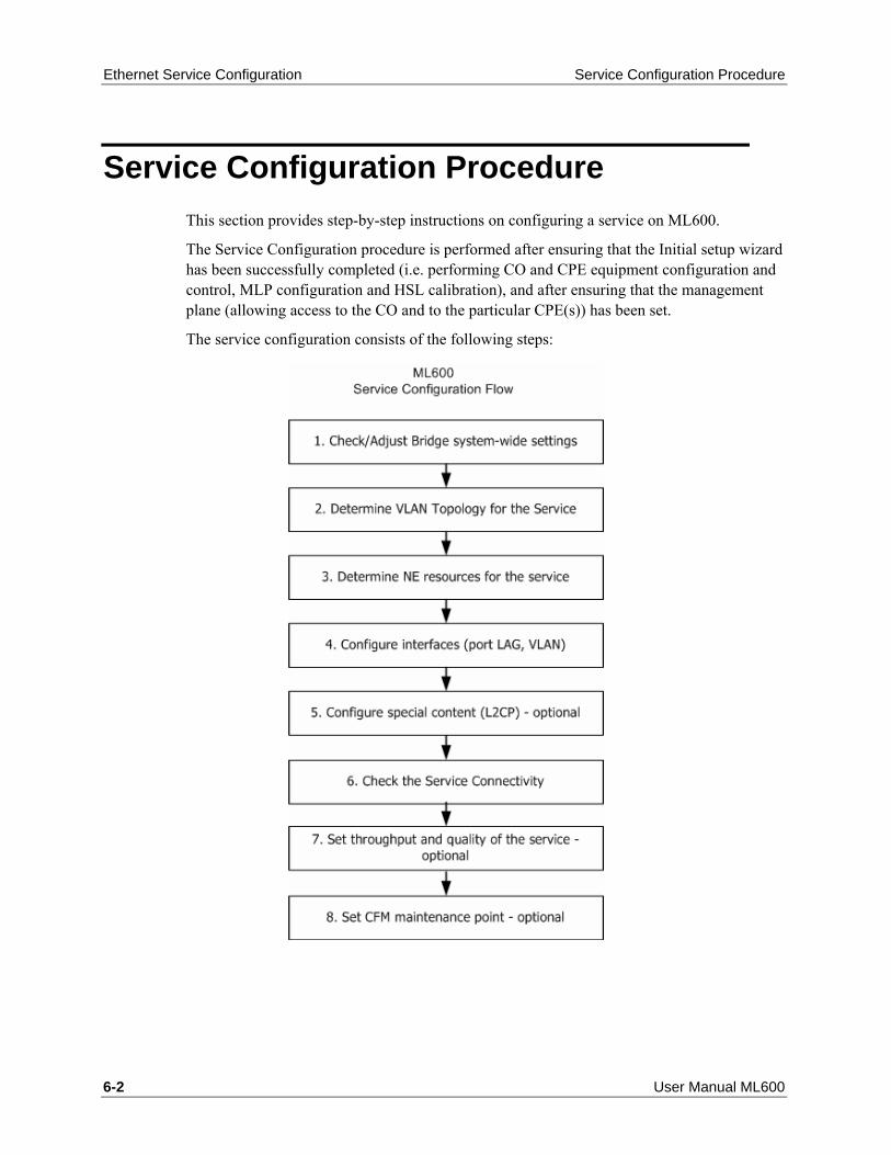
Ethernet Service Configuration Service Configuration Procedure
6-2 User Manual ML600
Service Configuration Procedure This section provides step-by-step instructions on configuring a service on ML600.
The Service Configuration procedure is performed after ensuring that the Initial setup wizard has been successfully completed (i.e. performing CO and CPE equipment configuration and control, MLP configuration and HSL calibration), and after ensuring that the management plane (allowing access to the CO and to the particular CPE(s)) has been set.
The service configuration consists of the following steps:

Service Configuration Details Ethernet Service Configuration
ML600 User Manual 6-3
Service Configuration Details Step 1: Check and Adjust Bridge system-wide settings
System-wide configurable parameters affect all services at once, so it is crucial to determine these configurations, which are applied system-widely, in advance and before any Ethernet Service is assigned.
For ML600 bridge system-wide configuration, follow Ethernet Bridge and STP/RSTP Configuration (on page 5-1) instructions.
Step 2: Determine VLAN topology for the Service
To determine the Service Topology, use VLAN schemes as shown in the VLAN Configuration (on page 7-1) chapter.
In order to determine the correct topology, consider the needs of the L2 Priority CoS bits preservation or modifications.
Assuming that only external VLAN tag is accessible on the CO NE, the topology should be selected to either propagate CoS bits to additional external VLAN tag or to modify the CoS bits according to the classification result on either CO or CPE.
For ML600 L2 Priority CoS bits control capabilities, refer to L2 Priority CoS bits Re-Marking (on page 5-14).
Step 3: Determine NE Resources for the Service
Allocate the physical interfaces (ports/LAGs) to be assigned for the Service on the CPE and the CO.
Determine media characteristics of the customer's equipment attached through the UNI (User-Network Interface) to the CPE NE and through the NNI (Network–Network Interface toward WAN/LAN) beyond the CO NE. These parameters include: electrical or optical cable type, MDI/MDIX connection to the router/hub or End-Station, interface speed, Auto-negotiation capabilities, LAG needs, LAG load sharing scheme, etc.
Verify that the OAM, LLCF and STP configuration is compatible with the service provider's Network definitions.
Step 4: Configure Ports, LAGs and VLAN for the Service
After making the above steps' configuration decisions, the CPE and the CO NEs (each NE separately) should now be configured according to the steps listed below.
Note: To avoid management connectivity loss with the CPE, it is recommended to first configure the CPE and then the CO.

Ethernet Service Configuration Service Configuration Details
6-4 User Manual ML600
1. To configure a LAG (if used):
• Generate the LAG entity first.
• Enable and add the new LAG to the LAG Ethernet Ports.
• Verify that all of the Ethernet ports which will be assigned to the LAG are adjusted with the same Speed attributes.
Note: the auto-mode cannot be used, and VLANs should not be assigned.
• Configure the VLAN to be applied to the LAGs. 2. To configure the Ports see Ethernet Port Configuration (on page 4-39). To configure
the LAGs, see Static Link Aggregation (LAG) Configuration (on page 4-52). 3. To configure the VLANs see VLAN Configuration (on page 7-1) Step 5: Control special content (L2CP) of the service
Configure the method in which the system handles L2CP frames (Eliminate / Handle / Tunnel), according to the Customer Service Requirements.
For more information see L2CP Processing (on page 8-1).
Step 6: Check the Service Connectivity
After completing the above steps, the Ethernet Service traffic is configured. At this phase, the Service Connectivity should be verified, and handled if needed, by performing the following tests:
• Send a Ping either to the CPE IP or to an IP beyond the CPE (if the customer LAN IPs are known) from the WAN Management host. In addition check Ping to the CO. If the ping fails, see Verifying Service Traffic and Connectivity (on page 14-81).
• Check the CPE ETH port (which was previously configured to support the service traffic) response to the commands: Suspend and Resume (the traffic should be stopped/resumed). For more information see Ethernet Service Suspension and Restoration (on page 14-93).
Step 7: Set Throughput and Quality of the Service
The service throughput and quality should be configured separately on the CPE and on the CO NE.
Depending on the CPE and CO NE models, throughput control can be applied as follows:
• Basic (per port, using ingress/egress rate limiting)
• Advanced (per flexibly identified flow – using rules of EVC services)

Service Configuration Details Ethernet Service Configuration
ML600 User Manual 6-5
When planning the network service flow, note that the Ethernet service throughput of the ML NEs (any model) is calculated as "Net" traffic; i.e. without the 20 bytes of the Ethernet media overhead (Inter-frame-Gap and Preamble) added to each Ethernet frame, but rather with the L2 frame content only.
For ML600 NE configuration instructions see Quality of Service (QOS) (on page 5-8), and Rate Limit Configuration (on page 4-50).
For ML640/650 NE configuration instructions see Quality of Service (QOS) (on page 5-8), Rate Limit Configuration (on page 4-50), and EVC Configuration (on page 9-1).
Step 8: Set CFM Maintenance Point
To complete the service provisioning, a CFM option can be enabled per EVC service flow, controlling end-to-end consistency of Ethernet Service configuration, and providing continuous connectivity check of Service traffic.
For more information about configuring the CFM Maintenance Point (either MIP or MEP) on CO and CPE NEs, see Ethernet CFM Configuration (on page 10-1).


ML600 User Manual 7-1
Actelis products use VLANs for cross-connections between Ethernet ports, providing both Ingress and Egress VLAN Forwarding Rules in a single operation – VLAN configuration.
In This Chapter
VLAN Configuration Principles ...................................... 7-2 Membership Principles .................................................. 7-3 Management VLAN Configuration................................. 7-9 Traffic VLAN Configuration.......................................... 7-11 VLAN Topologies ........................................................ 7-13
. 7 7 VLAN Configuration

VLAN Configuration VLAN Configuration Principles
7-2 User Manual ML600
VLAN Configuration Principles VLAN are separately configured for Customer service traffic (Traffic VLANs) and Actelis Product NE management traffic (Management VLAN). Traffic VLANs can be edited, added and deleted, while the Management VLAN can only be edited.
Note: VLAN Editing operation causes a short disruption in the traffic.
VLAN ID, VLAN name, VLAN type, VLAN port members and VLAN membership type are configured per each VLAN.
• VLAN ID - defines a unique identification of a cross-connect between ML device ports, which participate in the specific Virtual LAN.
• VLAN name - textual description of the cross-connect.
• VLAN type - defines the VLAN as either Traffic or Management. Only Management VLAN includes implicitly (not user configurable) a CPU of ML Device, which allow ML device Management access. Traffic VLANs will never access the CPU of ML Device.
• VLAN port member parameter - defines the group of ports, which belong to the particular Virtual LAN. The traffic is forwarded between VLAN members only, limiting unknown MAC broadcast.
VLAN membership type parameter is specified per each VLAN port member and defines both frame filtering and frame modification behavior of the port by a single parameter.
Filtering action types are one of the following: 1. Accept ANY traffic (VLAN-tagged or VLAN-untagged. 2. Accept only VLAN-untagged traffic. 3. Filter particular VLAN-tagged traffic. Modification action types are: 1. Do not modify the frame. 2. Strip (on egress) and insert(on ingress) a new Tag. Actelis products support 3 combinations of membership type called Untagged, Tagged, Stacked. For more information see VLAN Membership Principles (on page 7-3).

Membership Principles VLAN Configuration
ML600 User Manual 7-3
Membership Principles Port membership to a VLAN is determined by the bridge port on which data frames are received. VLAN cross-connections provide forwarding rules applied on each port configured as member in a specific VLAN. The guidelines provided in this section explain various VLAN port membership forms.
VLAN Membership Forms There are three membership forms for ports participating in a VLAN:
• Ports that are tagged members of a VID
• Ports that are untagged members of a VID
• Ports that are stacked members of a VID
The following figure shows how ports that are tagged members of a VID handle incoming and outgoing frames.
Figure 14: Port is Tagged Member of VID=XXX

VLAN Configuration Membership Principles
7-4 User Manual ML600
Table 17: Tagged Member Description Summary
Direction Description
In Allows Tagged (=VID) Traffic only. Out No change (tagged traffic).
The following figure shows how ports that are untagged members of a VID handle incoming and outgoing frames.
Port is Untagged Member of VID=XXX
Table 18: Untagged Member Description Summary
Direction Description
In Allows Untagged Traffic and Tagged Traffic with VLAN ID equal to PVID. For Untagged Traffic adds VLAN tag equal to PVID.
Out Strips VLAN Tag (PVID).

Membership Principles VLAN Configuration
ML600 User Manual 7-5
The following figure shows how ports that are untagged members of a VID handle incoming and outgoing frames.
Figure 15: Port is Untagged Member of VID=XXX
Table 19: Stacked Member Description Summary
Direction Description
In Allows any traffic and always adds a VLAN tag Out Strips VLAN Tag (PVID)

VLAN Configuration Membership Principles
7-6 User Manual ML600
VLAN Membership Rules Generally, ports can be specified as Tagged, Stacked or Untagged per VLAN and can be allocated to multiple VLANs. However there are some membership limitations as described in this section.
Table 20: VLAN Membership Rules
Ports specified as... Cannot be specified as... Relevant Systems
Untagged member of a VLAN Untagged member of any other VLAN
All ML products
Stacked member of a VLAN Stacked member of any other VLAN All ML products Stacked member of a VLAN Member of any other VLAN ML600 products Stacked member of a VLAN SW version R5.20 (and lower):
Member of any other VLAN EXCEPT as an Untagged member of MGMT VLAN SW version R6.0 (and higher): TRFC VLAN CAN be specified as an Untagged member
ML130/ML1300/ML2300
Tagged member of a VLAN that includes stacked members
A tagged member of a VLAN with other untagged ports or a VLAN with other stacked ports
ML600

Membership Principles VLAN Configuration
ML600 User Manual 7-7
Note: In addition, VLAN that have a Stacked port member, can have only ONE Tagged member;
The following three figures illustrate the rules for Multiple VLANs that are members of the same port.

VLAN Configuration Membership Principles
7-8 User Manual ML600

Management VLAN Configuration VLAN Configuration
ML600 User Manual 7-9
Management VLAN Configuration By factory default, the management VLAN is set to 100, allowing VLAN-unaware management traffic via COLAN (MGMT) port (out-of-band only).
In the following case you may want to change the default:
• If it is required to use in-band management to eliminate the need for a separate connection to the COLAN (MGMT) port of the ML device. In this case, modify the Management VLAN ID accordingly, and select one of the service ports as a member;
• If out-of-band management traffic is tagged. In this case, modify the COLAN (MGMT) port to be a tagged member of the Management VLAN;
• If the assigned Management VLAN ID is already used in the MAN/WAN for traffic. In this case, select a different VLAN ID for Management, equal to that used in MAN/WAN for management purposes.
The following limitations are applied on the COLAN port/MGMT VLAN:
• A single Management VLAN is allowed in Actelis systems;
• Management VLAN cannot have stacked members;
• COLAN can be deleted from the MGMT VLAN and must be specified in MGMT VLAN;
• MGMT VLAN = 100 is defined on all HSLs (as Tagged member) regardless of their provisioning status (even deleted).
To edit the management VLAN: 1. In the Network Element tree, open Ethernet Bridge. 2. Open VLANs. The VLANs pane opens. 3. From the VLANs table, select the management VLAN ID. 4. Click Edit VLAN. The Edit Management VLAN dialog appears.

VLAN Configuration Management VLAN Configuration
7-10 User Manual ML600
5. In the VID box, type the VLAN number. 6. For VLAN name, in the Name box, enter the VLAN name (up to 16 characters). 7. In the Service Port area, select either COLAN or ETH <ID> check box. Also select the
VLAN membership option (Untagged,Tagged or Stacked) for this port according to Provider/Customer network requirements.
Note: ETH <AID> as a regular Ethernet port, can be assigned as member of management VLAN, providing in-band management.
8. In the HSL Port area, select the HSL-1 check box (only Tagged membership option is available for HSL). For ML688, HSL-1 and HSL-2 are defined.
9. Click OK.

Traffic VLAN Configuration VLAN Configuration
ML600 User Manual 7-11
Traffic VLAN Configuration When configuring a traffic VLAN, take the following into account:
• Coordinate the VLAN number with the customer switch (network environment).
• On ML600 models, if PPPoE option is enabled, VID=4094 and 4093 are reserved for system use and cannot be configured.
• On ML650 models VID=4092 is reserved for system use and cannot be configured.
• All Ethernet ports including COLAN can be Untagged, Tagged or Stacked member of the traffic VLAN.
• If the VLAN has Stacked and Tagged ports, when Customer traffic is untagged, L2 Classification does not work on Tagged port (HSL). Therefore, if HSL BW is greater than the ETH BW (limited by Port Mode), congested packets will be randomly dropped.
To add a VLAN
Note: This procedure is also relevant to Editing a VLAN (Edit VLAN).
1. In the Network Element tree, expand Ethernet Bridge and open VLANs. The VLANs
pane opens in the work area.

VLAN Configuration Traffic VLAN Configuration
7-12 User Manual ML600
2. Click Add VLAN. The Add Traffic VLAN dialog appears.
3. To assign one or more ports to a single VLAN:
• Enable VID and assign the VLAN number.
• You may assign the VLAN a name, in the Name box. Range: up to 16 characters.
To assign one or more ports simultaneously to more than one VLAN: Enable From VID and enter a range of VLANs. Range: up to 4095
4. In the Service Port area, select either COLAN or ETH <ID> check box.
Note: COLAN as a regular Ethernet port, can be assigned as member of any traffic VLAN.
5. Select the VLAN membership type for this port according to Provider/Customer network requirements: : Untagged,Tagged or Stacked
6. Select the HSLs:
• In the HSL Port area, select the HSL-1 check box (HSLs are always tagged members)
• For ML688, HSL-1 and HSL-2 are defined. 7. Click OK.

VLAN Topologies VLAN Configuration
ML600 User Manual 7-13
VLAN Topologies Actelis equipment allows building various Ethernet topologies in Service and Management Traffic planes.
Prior to Ethernet topology planning verify and perform the following:
• Verify that there are no loops in the Ethernet Topology - use Spanning Tree Protocol if there are redundant connections;
• Check MFS (Maximum Frame Size) size of frames - each new S-VLAN tag adds to the frame an additional 4 bytes. Calculate the largest expected MFS size and check that it is acceptable in the whole Network;
• Ethernet Type of S-VLAN tag (default 0x8100 Q-n-Q Cisco) can be changed, but should be acceptable on each Hop device;
• Separate Customer and Provider Bridges Control planes - configure rules of L2CP.
This chapter provides examples of useful Ethernet topologies, with a description on how to configure Actelis NEs to achieve each of them.
The desired topology should be carefully planned prior to configuration, preventing Management LAN connectivity lost.
How to avoid L2 connectivity loss during Ethernet topology configuration:
• Plan or select one of proposed topologies prior to configuration;
• Remember that the Management traffic plane may be affected by the Service traffic plane you selected;
• Start from the most remote NE (from the Management Host);
• Start with the Management plane, not the Traffic plane configuration;
• If integrity is lost, restore connection using Non-IP access to Linked by HSL NEs. The channel works from the CO to CPE direction only and allows restoring the Management LAN integrity.
Note: All Actelis NEs may perform as VLAN-aware (Q-bridge) or VLAN-unaware (D-bridge) Ethernet Switches. Installations, which use different bridge modes (Q and D) on various NEs, are possible but are not described in the examples below, and should be carefully planned by the Providers' Ethernet Network Engineer.

VLAN Configuration VLAN Topologies
7-14 User Manual ML600
Symmetric Topologies In symmetric topologies, traffic beyond the ML edge devices (CO and CPE) is forwarded unchanged. The symmetric topology matches with P2P installation needs, where ML NE is used as a media converter only or where Customer and Provider site L2 plane is flatly merged.
The following configurations of the ML link work for symmetric topologies:
• HUB;
• TUNNELS;
• Transparent for ANY Customer traffic;
• Transparent for Untagged Customer traffic;
• Transparent for Specified Tagged Customer traffic (CE-VID filtering);
• DROP-and-CONTINUE.
HUB configuration is applicable in any deployment, providing VLAN-unaware (802.1D) behavior on each NE. Management traffic in this configuration can be either VLAN-tagged or VLAN-untagged, as desired.
TUNNELS configuration, which is suitable for P2P deployments, providing transparent (frames are unchanged beyond the ML systems) and separate (each port is protected from other ports by an internally applied VLAN) tunnels through the ML between the 10/100/100BT/FX Port connected to the PAF-2BaseTL Port. Management traffic in this configuration can be either VLAN-tagged or VLAN-untagged, as desired. There are 2 different configurations that can achieve Transparent behavior of service traffic, one allowing in-band and out-of-band management (with some limitations regarding Service Traffic), another allowing out-of-band management only (without limitations on Service Traffic).
DROP-and-CONTINUE configuration, supported using ML688 model, provides tunnels through all installed ML(s) and also provides up to 4 ETH ports, participating in the tunnel, on each site, where ML688 is installed.
HUB Topology In HUB mode, usually used in Campus /Enterprise environment, Actelis NEs behave as a VLAN unaware switch (802.1D), where user cannot configure any VLANs.
Full connectivity is permitted from any port to any other port. Switching is done strictly based on MAC address, ignoring VLAN information.
To configure "HUB" service traffic topology:
• Set Bridge Mode= 802.1D on all NEs, starting from the most remote NE.

VLAN Topologies VLAN Configuration
ML600 User Manual 7-15
Note that in HUB mode management traffic is not separated from the Service Traffic and thus cannot be terminated, i.e. there is no management demarcation point. VLAN-tagged Management traffic can be recognized by Actelis NEs as well as VLAN-untagged Management traffic.
Figure 16: VLAN-unaware Customer traffic Switching

VLAN Configuration VLAN Topologies
7-16 User Manual ML600
Transparent for ANY Customer Traffic
Figure 17: Tunnels for any type of Customer Traffic, without Out-of-Band Untagged MGMT traffic
Table 21: Configuration summary for “Tunnels for Any service traffic type:
CO NE CPE NE
ETH-x [Stacked] for TRFC VID ETH-x [Stacked] for TRFC VID HSL-1 [Tagged] for TRFC VID and [Tagged] for MGMT VID
HSL-1 [Tagged] for TRFC VID and [Tagged] for MGMT VID
COLAN [Untagged] for MGMT VID COLAN [Untagged] for MGMT VID (optional).

VLAN Topologies VLAN Configuration
ML600 User Manual 7-17
Transparent for Untagged Customer Traffic
Figure 18: Tunnels for Untagged or Tagged with VID=PVID Customer Traffic, with In-band Tagged MGMT Traffic
Table 22: Configuration summary for “Tunnels for Untagged/Tagged with VID=PVID service traffic type”:
CO NE CPE NE
ETH-x [Untagged] for TRFC VID and [Tagged] for MGMT VID
ETH-x [Untagged] for TRFC VID and [Tagged] for MGMT VID (optional)
HSL-1 [Tagged] for TRFC VID and [Tagged] for MGMT VID
HSL-1 [Tagged] for TRFC VID and [Tagged] for MGMT VID
COLAN [Tagged or Untagged] for MGMT VID (require STP)
COLAN [Tagged or Untagged] for MGMT VID (optional) (require STP)

VLAN Configuration VLAN Topologies
7-18 User Manual ML600
Transparent for Specified Tagged Customer Traffic (CE-VID Filtering) This configuration, applicable in any deployment, uses the same encapsulation level (VLAN tag) for switching in Customer LAN and Provider WAN and between them. Management traffic in this configuration can be either VLAN-tagged or VLAN-untagged, as desired. In-band management traffic beyond the CO and the CPE is also available.
To configure the LAN topology:
• Obtain the VID(s) (VID = 1 to 4095) to represent the Customer in Provider Network (by SE-VID). Service Edge VLAN (SE-VID) can be added on each NE (CO or CPE or both).
• Obtain the VLAN tag Ethernet type according to the Provider Network rules (default is 0x8100, like as in Cisco's Q-in-Q implementation);
• Launch MetaASSIST View Application and connect to the NE on CO via craft (recommended);
• Please use Online Help, available in MetaASSIST View, to get a detailed description on how to perform the following configuration;
• Configure obtained Ethernet Type as desired on CO and CPE NEs;

VLAN Topologies VLAN Configuration
ML600 User Manual 7-19
• Configure chosen VID on all NEs, starting from the most remote NE, using the guidelines for each topology, as described below.
Figure 19: Tagged Customer Traffic filtering, with in-band or out-of-band Tagged MGMT Traffic available.
Table 23: Configuration summary for “CE-VID no filtering, without preserving”
CO NE CPE NE
ETH-x [Tagged] for TRFC VID and [Tagged] for MGMT VID.
ETH-x [Tagged] for TRFC VID and [Tagged] for MGMT VID (optional).
HSL-x [Tagged] for TRFC VID and [Tagged] for MGMT VID.
HSL-1 [Tagged] for TRFC VID and [Tagged] for MGMT VID.
COLAN [Tagged or Untagged] for MGMT VID (optional, require STP).
COLAN [Tagged or Untagged] for MGMT VID (optional).

VLAN Configuration VLAN Topologies
7-20 User Manual ML600
Configuration Procedure
Figure 20: Chained Tunnels for untagged Customer Traffic, with in-band Tagged MGMT Traffic
Table 24: Configuration summary for “Chained Tunnels for Untagged/Tagged with VID=PVID traffic”:
CO NE Intermediate NE (optional) CPE NE
ETH-x [Tagged] for TRFC VID and [Tagged] for MGMT VID.
ETH-x [Untagged] for TRFC VID and [Tagged] for MGMT VID (optional).
ETH-x [Untagged] for TRFC VID and [Tagged] for MGMT VID (optional).
HSL-1 [Tagged] for TRFC VID and [Tagged] for MGMT VID.
HSL-1 & HSL-2 are [Tagged] for TRFC VID and [Tagged or Untagged] for MGMT VID.
HSL-1 [Tagged] for TRFC VID and [Tagged or Untagged] for MGMT VID.
COLAN [Tagged or Untagged] for MGMT VID (require STP).
Optional (as on CO NE). Optional (as on CO NE).

VLAN Topologies VLAN Configuration
ML600 User Manual 7-21
Asymmetric Topologies In asymmetric topologies ML NEs change the traffic, allowing inter-connect Customer and Provider side L2 planes using VLAN stacking (adding SE-VLAN(s) in Provider direction and stripping the SE-VLAN(s) in Customer direction).
The following configurations of ML link work for asymmetric topologies:
• Stacked on CPE (per-CPE-port), no CE-VID filtering;
• Stacked on CO (per-CPE), CE-VID filtering is possible;
• Stacked on both CPE (per-CPE-port) and CO (per-CPE), no CE-VID filtering.
Stacked on CPE (per-CPE-port), no CE-VID filtering
This configuration applicable in any deployment, encapsulates all customers' frames (tagged and untagged, without filtering of CE-VID) using an additional SE-VID tag. This configuration also allows multiple SE-VIDs per CPE (one per port), supporting multiple customers per CPE. In addition, allows intra-switching between CPEs, using switching between HSL ports (belonging to the same SE-VID) on CO NE. Management traffic in this configuration can be either VLAN-tagged or VLAN-untagged, as desired. In-band management traffic beyond the CPE is unsupported in this case.
Stacked on CO (per-CPE), CE-VID filtering is possible
This configuration applicable in any deployment, allows filtering of CE-VID on CPE and on CO encapsulates all permitted customer frames by additional SE-VID tag (one per each CPE). This configuration also allows intra-switching between CPEs, using switching between HSL ports (belonging to the same SE-VID) on CO NE. Management traffic in this configuration can be either VLAN-tagged or VLAN-untagged, as desired. In-band management traffic beyond the CPE is also available. This configuration allows Management VID re-mapping (applicable in case when MGMT VID contradict with CE-VID on CPE).
Note: Switch from CPE stacking topology to CPE filtering topology requires to delete all current Traffic VLANs and create new Traffic VLANs instead.
Stacked on both CPE (per-CPE-port) and CO (per-CPE), no CE-VID filtering
This configuration applicable in any deployment, accepts all customer traffic, encapsulates it twice by External SE-VID and Inner SE-VID tags which are applied on CO NE and CPE NE accordingly. In case of tagged Customer traffic, triple-tagged frames should be processed (cause additional 6 bytes of MFS size required on WAN/MAN equipment).
Management traffic in this configuration has the following limitations:
• CO management traffic can be either tagged or un-tagged (in-band or out-of-band).

VLAN Configuration VLAN Topologies
7-22 User Manual ML600
• CPE management traffic should be dual-tagged (with Inner SE-MGMT-VID (limitation of HSL port of CPE by ML600) and with External SE-TRFC-VID (to pass through CO)).
The follow sections provide schemes and the configuration order for all listed topologies above.
Stacked on CPE (per-CPE-port), no CE-VID Filtering This configuration applicable in any deployment, encapsulates all customers' frames (tagged and untagged, without filtering of CE-VID) using an additional SE-VID tag. This configuration also allows multiple SE-VIDs per CPE (one per port), supporting multiple customers per CPE. In addition, allows intra-switching between CPEs, using switching between HSL ports (belonging to the same SE-VID) on CO NE. Management traffic in this configuration can be either VLAN-tagged or VLAN-untagged, as desired. In-band management traffic beyond the CPE is unsupported in this case.
To configure the LAN topology:
• Obtain the VID(s) (VID = 1 to 4095) to represent the Customer in Provider Network (by SE-VID). Service Edge VLAN (SE-VID) can be added on each NE (CO or CPE or both).
• Obtain the VLAN tag Ethernet type according to the Provider Network rules (default is 0x8100, like as in Cisco's Q-in-Q implementation);
• Launch MetaASSIST View Application and connect to the NE on CO via craft (recommended);
• Please use Online Help, available in MetaASSIST View, to get a detailed description on how to perform the following configuration;
• Configure obtained Ethernet Type as desired on CO and CPE NEs;

VLAN Topologies VLAN Configuration
ML600 User Manual 7-23
• Configure chosen VID on all NEs, starting from the most remote NE, using the guidelines for each topology, as described below.
Figure 21: CE-VID preserving without filtering, stacked per each Port on CPE NE.
Table 25: Configuration summary for “CE-VID preserving/no filtering, with stacking per CPE port”
CO NE Intermediate NE (optional) CPE NE
ETH-x [Tagged] for TRFC VID and [Tagged] for MGMT VID (optional).
ETH-x [Untagged] for TRFC VID. ETH-x [Stacked] for TRFC VID.
HSL-x [Tagged] 1 for TRFC VID and [Tagged] for MGMT VID.
HSL-1 and HSL-2 are [Tagged] for TRFC VID and [Tagged] MGMT VID.
HSL-1 [Tagged] for TRFC VID and [Tagged] for MGMT VID.
COLAN [Tagged or Untagged] for MGMT VID.
COLAN [Tagged or Untagged] for MGMT VID (optional).
COLAN [Tagged] for MGMT VID (optional).

VLAN Configuration VLAN Topologies
7-24 User Manual ML600
1 Note: Equal VID on multiple HSL provides intra-switching between appropriate ports of appropriated CPEs.
Stacked on CO (per-CPE), CE-VID Filtering is Possible This configuration applicable in any deployment, allows filtering of CE-VID on CPE and on CO encapsulates all permitted customer frames by additional SE-VID tag (one per each CPE). This configuration also allows intra-switching between CPEs, using switching between HSL ports (belonging to the same SE-VID) on CO NE. Management traffic in this configuration can be either VLAN-tagged or VLAN-untagged, as desired. In-band management traffic beyond the CPE is also available. This configuration allows Management VID re-mapping (applicable in case when MGMT VID to contradict with CE-VID on CPE).
To configure the LAN topology:
• Obtain the VID(s) (VID = 1 to 4095) to represent the Customer in Provider Network (by SE-VID). Service Edge VLAN (SE-VID) can be added on each NE (CO or CPE or both).
• Obtain the VLAN tag Ethernet type according to the Provider Network rules (default is 0x8100, like as in Cisco's Q-in-Q implementation);
• Launch MetaASSIST View Application and connect to the NE on CO via craft (recommended);
• Please use Online Help, available in MetaASSIST View, to get a detailed description on how to perform the following configuration;
• Configure obtained Ethernet Type as desired on CO and CPE NEs;

VLAN Topologies VLAN Configuration
ML600 User Manual 7-25
• Configure chosen VID on all NEs, starting from the most remote NE, using the guidelines for each topology, as described below.
Figure 22: CE-VID preserving with filtering, VLAN stacking on CO NE per whole CPE NE
Table 26: Configuration summary for “CE-VID preserving with filtering, with stacking on CO, per CPE”
CO NE Intermediate NE (optional) CPE NE
ETH-x [Tagged] for TRFC VID and [Tagged] for MGMT VID (optional), (require STP).
ETH-x [Untagged] for TRFC VID. ETH-x [Tagged or Untagged] for TRFC VID.
HSL-x [Stacked] for TRFC VID and [Untagged] for MGMT VID.
HSL-1 [Tagged] for TRFC VID, HSL-1 [Untagged] for MGMT VID. HSL-2 [Tagged] for TRFC VID, HSL-2 [Untagged] for MGMT VID.
HSL-1 [Tagged] for TRFC VID, HSL-1 [Untagged] for MGMT VID.
COLAN [Tagged or Untagged] for MGMT VID.
COLAN [Untagged] for MGMT VID (optional).
COLAN [Untagged] for MGMT VID (optional).

VLAN Configuration VLAN Topologies
7-26 User Manual ML600
Stacked on CO (per-CPE) with CO and CPE Separated Management
Management Traffic toward CO and CPE may belong to different MGMT VLANs. To achieve this functionality, the following configuration should be applied:
• A port on the CO NE should be configured with two TRFC VLANs:
• TRFC VLAN with STACKED membership will serve Tagged Traffic (VID=20 in the illustration below). All Customer traffic, passed through CPE is tagged – natively from Customer Side, or being modified on UNTAGGED port – where default Port VID is added
• TRFC VLAN with UNTAGGED membership will serve Untagged Traffic (VID=200 in the illustration below). Only CPE Management traffic should be untagged.
• MGMT VLAN ID on the CO NE (VID=100 in the illustration below) should NOT include HSL port; i.e. CO Management traffic should not pass to the CPE on Customer side
• MGMT VLAN ID on CPE NE (VID=200 in the illustration below) should be set on CPE NE only. The same VID on the CO NE is configured as a TRFC VLAN (see above).

VLAN Topologies VLAN Configuration
ML600 User Manual 7-27
The next drawing illustrates configuration and traffic flow in case of CO/CPE Different Management VLANs
Stacked on CO (per-CPE) with CPE in D-bridge Mode
When a CPE is configured in D-bridge mode (VLAN–unaware), service traffic from- and to- CPE is transported transparently (tags are disregarded) to/from the CO.
If the TRFC VLAN on the CO HSL port is configured as Stacked and the MGMT VLAN is configured as Untagged, the Untagged Service Traffic from the CPE will be accepted as Management traffic (and broadcast by CO CPU to all Management VLAN members). This will cause undesired Ethernet loops and other transportation faults.
The correct configurations for this type of deployment are:
• For deployment with mixed (Tagged and Untagged) customer traffic (when CPE is in D-bridge mode) - CO HSL should be configured with Stacked TRFC VLAN only.
CPE management communication can be achieved only through non-IP CPE access (no VLAN, IP configuration required). This case is illustrated in the figure below.

VLAN Configuration VLAN Topologies
7-28 User Manual ML600
• For deployment with Untagged customer traffic only (when CPE is in D-bridge mode) - CO HSL should be configured with Untagged TRFC VLAN to accept and encapsulate Service Traffic.
In this case the only way (except non-IP CPE access) CPE management communication can be achieved is an additional Tagged MGMT VLAN on CO NE HSL (meaning that CPE Management traffic must be Tagged and CPE NE D-bridge parameters should be configured accordingly to specify MGMT VLAN on CPE).
• For deployment with Tagged customer traffic only (when CPE is in D-bridge mode) - CO HSL should be configured with Tagged TRFC VLAN(s) to accept Service Traffic.
In this case CPE management communication can be achieved by MGMT VLAN configured on CO HSL - either Tagged (if Management traffic is tagged) or Untagged (if Management traffic is untagged). Non IP-CPE access option is also available in such deployments.

VLAN Topologies VLAN Configuration
ML600 User Manual 7-29
Stacked on both CPE (per-CPE-port) and CO (per-CPE), no CE-VID Filtering This configuration applicable in any deployment, accepts all customer traffic, encapsulates it twice by External SE-VID and Inner SE-VID tags which are applied on CO NE and CPE NE accordingly. In case of tagged Customer traffic, triple-tagged frames should be processed (cause additional 6 bytes of MFS size required on WAN/MAN equipment). Management traffic in this configuration has the following limitations. CO management traffic can be either tagged or un-tagged (in-band or out-of-band). CPE management traffic should be dual-tagged (with Inner SE-MGMT-VID (limitation of HSL port of CPE by ML600) and with External SE-TRFC-VID (to pass through CO).
To configure the LAN topology:
• Obtain the VID(s) (VID = 1 to 4095) to represent the Customer in Provider Network (by SE-VID). Service Edge VLAN (SE-VID) can be added on each NE (CO or CPE or both).
• Obtain the VLAN tag Ethernet type according to the Provider Network rules (default is 0x8100, like as in Cisco's Q-in-Q implementation);
• Launch MetaASSIST View Application and connect to the NE on CO via craft (recommended);
• Please use Online Help, available in MetaASSIST View, to get a detailed description on how to perform the following configuration;
• Configure obtained Ethernet Type as desired on CO and CPE NEs;

VLAN Configuration VLAN Topologies
7-30 User Manual ML600
• Configure chosen VID on all NEs, starting from the most remote NE, using the guidelines for each topology, as described below.
Figure 23: CE-VID preserving without filtering, VLAN dual stacking (per CPE port and per whole CPE)

VLAN Topologies VLAN Configuration
ML600 User Manual 7-31
Configuration summary for “Dual CE-VID preserving/no filtering, stacking on CPE and CO”
CO NE Intermediate NE (optional) CPE NE
ETH-x [Tagged] for TRFC VID. ETH-x [Tagged] for MGMT VID (to manage CO NE). ETH-x [Stacked] for MGMT VID (to access CPE NE for management, traffic should pass through HSL as service traffic).
ETH-x [Tagged] for TRFC VID. ETH-x [Stacked] for TRFC VID.
HSL-x [Stacked] for TRFC VID (no MGMT VID through HSL, it is encapsulated by TRFC VID to achieve CPE NE).
HSL-1 [Tagged] for TRFC VID,HSL-1 [Tagged] for MGMT VID. HSL-2 [Tagged] for TRFC VID,HSL-2 [Tagged] for MGMT VID.
HSL-1 [Tagged] for TRFC VIDHSL-1 [Tagged] for MGMT VID.
COLAN [Tagged or Untagged] for MGMT VID (to manage CO NE) (optional)(require STP).
COLAN [Untagged] for MGMT VID (optional).
COLAN [Untagged] for MGMT VID (optional).


ML600 User Manual 8-1
Layer 2 Control Protocols (L2CP) is a group of protocols standardized by IEEE 802.1, which are used by both Service Provider and Customer L2 Switching Devices. The group of protocols is identified by its destination MAC address. Each ML system allows per port behavior control over each MAC address of an L2CP group. The following behavior can be defined:
- Discarding of undesired L2CP frames in Service Provider Network Customer and vice versa, which provides full demarcation (as specified in IEEE 802.1ad standard) between Service and Customer L2 Switching devices.
- Peering (accepting and locally handling) of all L2CP frames, which provides convergence of all L2 Switching devices into the one common network.
- Tunneling (as specified in MEF-10), i.e. ability to forward Customer L2CP frames through Provider Network. Two types of tunneling are supported: Transparent and VLAN Tagged.
In This Chapter
Supported L2CP Protocols............................................ 8-2 Configuring Handling of L2CP Frames.......................... 8-3 Deployment Considerations .......................................... 8-6
. 8 8 L2CP Processing

L2CP Processing Supported L2CP Protocols
8-2 User Manual ML600
Supported L2CP Protocols IEEE 802.1 defines L2CP Reserved MAC addresses in a range from 01-80-C2-00-00-00 to 01-80-C2-00-00-2F. ML systems support control only on those addresses, which are already assigned by IEEE 802.1 standard to defined and working protocols: 01-80-C2-00-00-00 to 01-80-C2-00-00-0F , 01-80-C2-00-00-10 , 01-80-C2-00-00-20 to 01-80-C2-00-00-21.
All other future-use reserved MAC addresses in the range are handled as a regular traffic, i.e. accepted, dropped or modified according to VLAN membership of the port and received frame format.
ML systems additionally allow control on Cisco Reserved MAC addresses per each port separately, supporting Layer 2 Cisco Frames (like PVST+, CDP, ISL) behavior control.
Initially, the ML system handles Cisco Reserved MAC addresses as a regular traffic, i.e. Cisco frames are accepted, dropped or modified according to VLAN membership of the port and received frame format. To change the behavior, and enable per ML port control over Cisco Reserved MAC addresses, change checkbox configuration on L2CP table pane.
In ML600, three dedicated MAC Addresses are handled as configured. These are:
• ISL 01-00-0C-00-00-00
• CDP 01-00-0C-CC-CC-CC
• PVST 01-00-0C-CC-CC-CD
All other MAC in "X" range on ML600 will behave as regular traffic, i.e. they will be accepted, dropped or modified according to VLAN membership of the port and received frame format.

Configuring Handling of L2CP Frames L2CP Processing
ML600 User Manual 8-3
Configuring Handling of L2CP Frames To configure processing of L2CP frames
1. In the Network Element tree, under Ethernet Bridge, select L2CP. The L2CP MAC Addresses pane showing the list of available L2CPs and corresponding MAC addresses appears.
Note: To configure Cisco Frames behavior, click the Configure Cisco Address button. Choose to either Drop the frames (default) or transparently transfer the frames to specified multiple ports - regardless of the VLAN membership rules for these ports.
2. Select the MAC address corresponding to the protocol to be applied on the port and click Configure Ports at the bottom of the pane. The following dialog appears. The dialog shows all the ports along with the way they will be processed and the egress ports.

L2CP Processing Configuring Handling of L2CP Frames
8-4 User Manual ML600
Note: The Init button is used to reassign a selected port its default L2CP definitions. The Init All Ports button is used to assign all ports their default L2CP definitions.
3. Select the port on which the previously selected protocol will be processed and click
Configure. The Behavior Configuration dialog appears. Note that only processing relevant to the selected protocol are enabled.
4. Select the method according to which the protocol frame will be processed:
• Discard - frame will be deleted providing demarcation (security) between the customer and provider networks.
• Peer - frame locally processed according to frame protocol. Requires that the ML is configured to support the application (i.e. STP, OAM, Pause Frame, etc.).

Configuring Handling of L2CP Frames L2CP Processing
ML600 User Manual 8-5
• Tunneling - Tunneling passes the customer control frames invisibly through to the provider's bridge. Two types of tunneling are available: Transparent and Tag (Tunneling by MAC is a future option):
• Transparent - passes the customer control frames invisibly through to the provider's defined Egress Port without modifying the header. Be sure tunneling is unidirectional and defined properly on either side of each link along the route. Manually configure the reverse direction of a transparent tunnel on all ports specified as Egress Ports.
• Tunnel by Tag Type - tags the frame and assigns it a VLAN ID. The frame is then passed to the defined Egress Port and tunneled through the network as if it was a regular data frame, according to the defined Tag and VLAN ID. After reaching its destination (UNI) the tag and VLAN ID are removed. The modifications are made only once on the CPE side. On the CO side, transparent tunneling is used. The reverse direction of a tagged tunnel is defined automatically on all ports specified as Egress Ports.
• Tunnel by MAC and VLAN ID - Modifies the customer frame DST address to a configurable MAC (only unicast address can be set) and encapsulates the frame within a VLAN tag (with a configurable VLAN ID and Ethernet Type which is set according to Bridge configuration). The frame is then passed to the provider's defined Egress Port and tunneled through the network as if it was a regular data frame, according to the defined MAC and VLAN ID. After reaching its destination (UNI), the MAC and VLAN ID are removed. The modifications are made only once on the CPE side. On the CO side, transparent tunneling is used. The reverse direction of a MAC tunnel is defined automatically on all ports specified as Egress Ports.
Note: Tunnel by MAC should not be configured on Ethernet Ports which participate in VLANs with stacked membership. In this case the configuration will not work.
5. Define the Egress Port (ETH-1 to ETH-5) via which the handled frame will be
forwarded to the network as follows:
• From the drop-down options box adjacent to the Add Port button, choose the Egress port.
• Click Add Port. The selected port will be added to the Egress Port list. (To remove a port, choose the port from the list and click Remove Port).
• Repeat to add ports to the list. 6. Click OK.

L2CP Processing Deployment Considerations
8-6 User Manual ML600
Deployment Considerations Special traffic (IEEE reserved multicast MAC addresses, Cisco management MAC addresses) from the customer's LAN can be tunneled through the service provider WAN without triggering L2 features (like STP) on service provider devices. This section provides several examples to illustrate the issue.
Case 1. Customer LAN uses Cisco equipment and Cisco's STP (but not PVST+), Provider WAN does not use STP
In most cases, Cisco equipment can be used in the customer's LAN without requiring complex configuration of the ML - ML default L2CP configuration is sufficient.
By default each ML NE forwards all Cisco traffic (0x01-00-0C-**-**-** reserved for proprietary Cisco protocols such as ISL, CDP, VTP, PVST+) as regular traffic (according to VLANs membership rules (on page 7-6) configured on the NE).
To restore the default setting:
• In the MetaAssist View, L2CP pane (on page 8-3), click the Configure Cisco Addresses button, select as Regular Service Traffic, and click OK.
• Repeat on all ML NEs participating in the forwarding.
Note: Cisco frames can be also enforcedly forwarded ignoring regular traffic VLAN rules, and using another VID dedicated for this purpose. For such deployment, use transparent tunnel (see below) on CPE and tunnel by TAG on CO.
Case 2. Customer LAN uses Cisco PVST+, Provider WAN does not use STP
In some customer LAN configurations, where Cisco proprietary PVST+ works as standard MSTP, it is additionally required to tunnel a standard BPDU frames (IEEE 802.1 Bridge Group Access address 0x01-80-C2-00-00-00). Such tunnel should be configured on CPE and CO ML on all Customer LAN sites using the following options: 1. Build transparent tunnel on CPE. This tunnel will forward the frame unchanged, cut-
through from Ingress to specified Egress ports, and ignore all VLAN filter, modification and forwarding rules configured on the NE. Transparent tunnel should be set on all directions – on port(s) facing Customer LAN and port(s) facing Network WAN. Repeat configuration on CPEs of all other customer site(s).

Deployment Considerations L2CP Processing
ML600 User Manual 8-7
2. Build tunnel by TAG (VID and optionally ETH-Type) on CO. This tunnel will forward the frame after inserting a TAG with the specified VID and ETH-Type. The VID should be set exactly as the Service VID (representing the Customer in WAN). This will allow to merge this special frame with all other customer traffic that is forwarded toward the service provider WAN. Tunnel by TAG is set manually only on ports ingressing from Customer side (HSL-x on CO). Note that the reverse direction of the tunnel on the same NE (ETH-x to HSL-x) is built automatically (and invisible in L2CP table). Repeat configuration on COs of all other customer site(s).
Note: You can apply TAG tunnel starting CPE (not very reasonable, but possible). Note do not use 0x8100 Eth. type if frame is tunneled via stacked ETH port.
Case 3A. Customer uses Cisco PVST+, Provider uses IEEE 802.1 STP/RSTP or Cisco PVST+.
In cases when BPDU frames (MAC 0x01-80-C2-00-00-00) are common for customer and service provider devices it can be recommended to use MAC tunneling applied on CPE (requires unicast MAC address to be used instead of MAC 0x01-80-C2-00-00-00).
The following configuration is allowed only if CPE has ETH port facing the customer switches as Untagged or Tagged. 1. Build tunnel by MAC (and VID) on CPE .This tunnel will forward the frame with MAC
DA modified to specified multicast address and also tagged with VID equal to one of the VID used for regular customer traffic forwarding. Tunnel by MAC is set manually only on port(s) facing Customer LAN. Note that the reverse direction of the tunnel on the same NE (HSL-1 to ETH-x) is built automatically. Repeat configuration on CPEs of all other customer site(s).
2. Use regular traffic VLANs on CO. Repeat configuration on COs of all other customer site(s).

L2CP Processing Deployment Considerations
8-8 User Manual ML600
Case 3B. Customer uses Cisco PVST+, Provider uses IEEE 802.1 STP/RSTP
In cases when BPDU frames (MAC 0x01-80-C2-00-00-00) are common for customer and service provider devices it can be recommended to switch Service Provider network (all devices, including ML CO and even ML CPE NEs) to Provider Bridge MAC BPDU frames (MAC 0x01-80-C2-00-00-08). 1. In the MetaAssist View, L2CP pane (on page 8-3), ensure that PEER handler is not
configured on any port for MAC 0x01-80-C2-00-00-00. 2. On L2CP pane, for MAC 0x01-80-C2-00-00-08, apply PEER handler on all ports
participating in the Provider Network and configure Drop handler on all Customer Facing (demarcation) ports.
3. On the Ethernet Bridge pane, click the Configure STP button, select Bridge Group Address equal to 0x01-80-C2-00-00-08 and Enable STP/RSTP. Click OK.
4. Repeat on all ML NE participating in the service provider STP.
Note: As demarcation between Provider / Customer Networks has no STP/RSTP solution, ensure that ETH loops are avoided there.

ML600 User Manual 9-1
This chapter describes how ML640/ML650 models implement Advanced Ethernet Services MEF features.
In This Chapter
Introducing MEF Terminology ....................................... 9-2 MEF10 QoS flow Overview ........................................... 9-4 Defining EVCs ............................................................... 9-5 Associating VLANs with EVC ........................................ 9-6 BW Profile Definition ..................................................... 9-7 EVC Services Definition ................................................ 9-9 Identification Rules Definition ...................................... 9-12 Deployment Considerations ........................................ 9-19
. 9 9 EVC Configuration

EVC Configuration Introducing MEF Terminology
9-2 User Manual ML600
Introducing MEF Terminology EVC, EVC Service, Identification Rules, and BW Profile abstracts are used on ML NE for advanced Ethernet Services MEF features configuration.
Identification Rules handle a fundamental MEF concept of Ethernet traffic analysis; the rule inspects the frame, searching for specific values at specific offsets, according to which the Ethernet frame is identified by the Ethernet Service to which it belongs.
The filters of the identification rules consist of:
• Ingress PORT (from which the frame has arrived)
• MAC Destination or Source Addresses
• External VLAN TAG with Ethernet Type, VLANID and COS bits
• Internal VLAN TAG with Ethernet Type, VLANID and COS bits
• IP Destination or Source Address
• TOS/DSCP bits
• Transport type (L3)
• Protocol type, source and destination ports (L4)
The identification rules can also be used:
• For additional L2 Priority CoS bits remarking (CoS out)
• As a firewall - to drop frames matched with specified filter(s)

Introducing MEF Terminology EVC Configuration
ML600 User Manual 9-3
The Bandwidth Profile handles a fundamental MEF concept of Ethernet Service throughput control. A pool of up to 32 profiles can be configured on each ML device. The same BW profile can be used by various Ethernet Services, simplifying the configuration process.
On the ingress port (prior to switch decision), the total bytes length and bits-per-second is metered for each frame and it is determined whether the rate for this Ethernet Service agreement (BW profile) was exceeded.
Three meter colors are used to distinguish between Committed (agreed for transmission with guaranteed quality of service) and Excessive (allowed for transmission but with unguaranteed quality) Informational rates (CIR and EIR). CIR and EIR rates are also provided with Burst Buffer Size (to allow some fluctuations of traffic rate). These are named: CBS (committed burst size) for CIR, and EBS (excessive burst size) for EIR. Traffic above CIR+EIR+CBS+EBS is dropped (policed) on ingress, avoiding switching resources usage.
On the egress port (after switch decision), each Ethernet service flow can be (optionally) shaped providing continuous un-bursty traffic transmission. The shaper rate is determined according to the assigned BW profile (as CIR + EIR), and prevents from arriving ingress bursts to be forwarded towards the next hop wire.
EVC Service handles the rest of the MEF fundamentals: a need for the Ethernet Service classification (i.e. a decision regarding the appropriate queue in which the frame will be stored prior to the transmission) and congestion avoidance control (how to schedule the queue, allowing the prioritization of one service flow versus another). EVC Service on ML NE is used for combining all of the above listed attributes:
• Identification Rule(s), identifying the EVC Service flow
• BW profile, to set throughput limits control on the EVC service flow
• Egress Class/Queue, Scheduler and Shaper
EVC (Ethernet Virtual Connection) handles a fundamental MEF concept of End-to-End Ethernet Services configuration. An EVC is an association of two or more User Network Interfaces (UNI), where the UNI is a standard Ethernet interface that is the point of demarcation between the Customer Equipment and the service provider's network.
EVC on ML NE is an abstract identification, which is not passed through the network via Ethernet Service frames, but is used as a group identifier of different local resources (specified by VLANs) used on each NE participating in the same Ethernet Service. VIDs configured on CPE and CO NE may differ (as C-VLAN and SP-VLAN), but when belonging to the same EVC, can be easily found for monitoring and maintenance.
In addition, EVC on ML NE is a place to keep a list of all the EVC services belonging to it. This allows to easily trace multiple EVC Services (like VoIP, FTP and HTTP) of the same EVC (like "Customer A").
EVC, once configured through ML CO and CPE with the same EVC description (i.e. "Customer A"), can be easily retrieved in glance on all NE and per each NE.

EVC Configuration MEF10 QoS flow Overview
9-4 User Manual ML600
MEF10 QoS flow Overview On ML640/ML650 models, MEF10 QoS handling is applied only on toward HSL direction and is combined with basic Quality of Service handling applied on regular ML600 models.
As shown on scheme above, MEF10 QoS setting do not provide Ethernet Service traffic connectivity between ports. Connectivity is provided by VLANs, which must be configured in advance.
In ML640/ML650 systems Ethernet Service configuration flow is:
• Define EVC (pool up to 8)
• Create BW profiles (pool up to 32) – for Service Throughput limitation.
• Define SERV (pool of 8) with selected BW profile to apply. Assign the SERV to EVC. Up to 8 SERV can be assigned to the same EVC.
• Define identification RULE (pool of 32 – seven of which are internally used) with particular L2, L3, L4 flow identification. Assign the RULE to SERV. Up to 32 RULES can be assigned to the same SERV.

Defining EVCs EVC Configuration
ML600 User Manual 9-5
Defining EVCs You may define up to eight EVC services.
To define an EVC 1. From the Network Topology tree, under Ethernet Services, select EVCs. The EVCs
pane appears. The pane lists the currently defined EVCs according to their EVC AID and EVC ID and provides EVC management functions.
2. To add an EVC:
• Click the Add button at the bottom of the pane. The Add EVC dialog appears.
• Select the relevant EVC AID from the list (up to 64 EVCs can be defined).
• Assign the EVC AID a meaningful EVC ID.
• Click OK. The description will be added to the EVC pane list.
Note: The defined EVC may be modified or deleted by selecting it and clicking the corresponding buttons at the bottom of the pane.

EVC Configuration Associating VLANs with EVC
9-6 User Manual ML600
Associating VLANs with EVC Traffic VLANs can be associated with predefined EVCs when the VLAN is defined or any time afterwards using the Edit option in the VLAN configuration pane.
Note: The following steps refer only to VLAN association to EVC. For a full description of the VLAN configuration procedure, refer to Traffic VLAN Configuration (on page 7-11).
To associate a VLAN with an EVC 1. In the Network Element tree, expand Ethernet Bridge and select VLANs. The VLANs
pane opens in the work area. 2. Invoke the configuration pane for the required VLAN using one of the following
methods:
• To add an existing VLAN to an EVC, select the VLAN row and click Edit VLAN.
• To add a new VLAN to an EVC, click Add VLAN. 3. In the invoked Traffic VLAN pane, define the necessary parameters and select the EVC
with which the VLAN will be associated.

BW Profile Definition EVC Configuration
ML600 User Manual 9-7
BW Profile Definition ML640 and ML650 supports the bandwidth profile definition (throughput) for each EVC service. A single Bandwidth Profile is applied to all ingress Service Frames. In the example illustrated below, there are three services, each identified by a CoS ID of the specific CE-VLAN - each with a separate Bandwidth Profile.
This section describes how to create a pool of bandwidth profiles (up to 32) with meaningful names. The profiles should be created according to the service provider's needs. They can then be used as part of the attributes that make up definitions for various services.
To define a bandwidth profile 1. From the Network Element tree, under Ethernet Services, select BW Profiles. The BW
Profile pane appears. The pane lists the currently defined pool of BW profiles (AID) along with their defined rate limits (CIR, CBS, EIR and EBS) and the services to which each profiles were assigned (Used by Services).
The operation buttons at the bottom of the pane are used to create and manage BW Profiles.

EVC Configuration BW Profile Definition
9-8 User Manual ML600
Use the the Rates (CIR/EIR) Presentation in option to configure the display of the BW rate.
2. To define a bandwidth profile:
• Click the Add button at the bottom of the pane. The Add BW Profile dialog appears.
• Select from the list of the available Profile IDs, where defined profiles are removed from the list: Range = BWPROFILE-0 to BWPRFILE-32
• Define the following for the profile:
o CIR (Committed Information Rate) - average rate up to which service frames are delivered. All service frames are sent at the UNI speed, e.g., 10Mbps, and not at the CIR, e.g., 2Mbps.
o CBS (Committed Burst Size) - the size up to which service frames may be sent and be CIR-conformant. Range: Unlimited or up to 16,000 Bytes.
o EIR (Excess Information Rate) - average rate, greater than or equal to the CIR, up to which service frames are delivered without any performance objectives.
o EBS (Excess Burst Size) - the size up to which service frames may be sent and be EIR-conformant. Range: Unlimited or up to 16,000 Bytes.
3. Click OK. The new profile will be added to the Bandwidth Profiles list.

EVC Services Definition EVC Configuration
ML600 User Manual 9-9
EVC Services Definition By factory default, ML640 is configured to use these services as follows:
• SERV-1 - for internal purposes, to allow L2CP and CFM features. Traffic of these features is identified using Rules-{1-6}; SERV-1 cannot be deleted but it’s queue, shaper and BW profile can be changed
• SERV-2 - to set the default behavior of unclassified traffic to be passed at least with lowest priority. Traffic is identified using Rule-32. SERV-2 cannot be deleted but it’s queue, shaper and BW profile can be changed
• SERV-3 – is used for default MGMT traffic and can be deleted and edited.
• SERV-4,5,6,7 – is used for default L2 COS bits classification and can be deleted and edited.
By factory default, ML650 is configured to use these services as follows:
• SERV-1 - for internal purposes, to allow L2CP and CFM features. Traffic of these features is identified using Rules-{5-10}; SERV-1 cannot be deleted but its queue, shaper and BW profile can be changed.
• SERV-2 - to set the default behavior of unclassified traffic to be passed at least with lowest priority. Traffic is identified using Rule-32. SERV-2 cannot be deleted but its queue, shaper and BW profile can be changed.
• SERV-3 – is used for default MGMT traffic and can be deleted and edited.
• SERV-4, 5, 6, 7 – is used for default L2 COS bits classification and can be deleted and edited.
• SERV-8 – is used for CES over ETH 4x DSx1 ports tunnel – can be deleted or edited.

EVC Configuration EVC Services Definition
9-10 User Manual ML600
Notes: 1. ML650 provides L2CP and CFM traffic prioritized (HHH) over DSx1 CES traffic (HH), this configuration can be changed. 2. ML650 provides a single CES tunnel (HH) for all four DSx1 ports (each one identified by a single rule). If required, DSx1 ports can be prioritized one to other, using various SERV AID per Rule with different Queues ID configured for each SERV AID.
To change the default behavior of the system - i.e. all unclassified traffic – to be dropped or prioritized, use Lower Order Rule (RULE-31 and lower) to define the behavior.
To define an EVC service 1. In the Network Topology tree, under Ethernet Services select EVC Services. The
Services pane appears. The pane lists the currently defined services along with their attributes.

EVC Services Definition EVC Configuration
ML600 User Manual 9-11
2. To add a Service, Click the Add Service button at the bottom of the pane. The Add Service dialog appears.
3. Select from the list of the available Service IDs. Up to 8 service IDs are supported
(SERV-1 to SERV-8). Only the available service IDs are displayed (i.e. defined services are removed from the list).
4. In the Description field, assign the service a meaningful name. 5. Select from the list of predefined BW Profiles. Only defined BW profiles are displayed.
If the required BW profile is not available, define it via the BW Profile option and it will be available for the service.
6. Select the Queue ID. 7. In the Shaper field, configure whether to apply shaper (Yes) or not (No) to the service as
the frames egress. The Shaper is used to limit data transmit rate and remove data bursts. In ML640/650 models, the shaper is available per queue, and when "Service per Queue" is configured, the shaper becomes a Service Shaper. Service Shaper rate limit is calculated automatically as the sum of CIR + EIR (specified in the BW profile(s) used by the Service(s) as Ingress Meter). For a Service with an enabled Shaper, it is recommended to use a BW profile which doesn't limit the CBS/EBS (should be set to unlimited), otherwise the shaper may work improperly.
Notes: Shaper cannot be enabled for a Service, if the CIR and/or EIR specified in the BW profile(s) used by that Service(s) are unlimited. Shaper cannot be enabled for a Service, if the total sum of CIR+EIR specified for that service(s) is greater than theoretically possible on the HSL port of the ML600 model.
8. Click OK. The new profile will be added to the Bandwidth Profiles list.
Note: The defined service may be modified or deleted by selecting it and clicking the corresponding buttons at the bottom of the pane.

EVC Configuration Identification Rules Definition
9-12 User Manual ML600
Identification Rules Definition ML640/ML650 supports up to 32 identification rules. Available by factory setup (see Appendix D - Factory Setup Content (on page 1)), default rules on ML640/ML650 enable forwarding tunnels for: 1. Ethernet packets belong to Layer 2 Control Protocols 2. Management LAN (MGMT VID=100) traffic 3. Other Traffic classified by Layer 2 COS bits 4. For ML650 - Circuit Emulation Service (CES) runs on reserved TRFC VID=4092 In ML640, the first six rules (identify reserved L2CP tunnel MAC addresses) cannot be deleted or modified. In ML650, additional four rules identify reserved Circuit Emulation Service (CES) tunnel and cannot be deleted (but can be re-assigned to different and various SERV-AID – to separate/prioritize CES tunnels). All other rules can be modified or deleted. The last rule identifies unclassified traffic and forwards it with a lowest priority through the system.
To change the default behavior of the system, i.e. drop or prioritize all unclassified traffic, the Lower Order Rule (RULE-31 and less) should be used to define the behavior.
The order of the identification rules is critical due to "First Match" principle implemented for Identification Rules on ML640/ML650. A new rule can be added in any available rows (the row number corresponds to the order of the rule). The order of configured rules (except for the first six on ML640 / first ten on ML650 and last rule) can be modified.
Note: To change the order of pre-defined rules, use the up and down arrows at the right of the rules table.
Rules can be imported (downloaded) to ML640/ML650 from a text file consisting of TL1 configuration commands.

Identification Rules Definition EVC Configuration
ML600 User Manual 9-13
To define an Identification Rule 1. In the Network Topology tree, under Ethernet Services, select Identification Rules.
The Frame Identification Rules pane appears. The example below shows ML650 rules.
The pane lists the currently defined Identification Rules along and provides access to rule management options via the buttons at the bottom of the pane. The buttons are:
• Details - provides information on the selected Rule.
• Configure rule - used to configure the attributes of the selected rule (for protected from modification rules this button is grayed-out).
• Clear Rule - used to clear the definitions of a selected rule.
• Load Config - used to load a text file of TL1 commands that defines the rule attributes.
1. Configure rules as follows:
• Select the appropriate rules from one of the rules available for configuration (the Configure Rule button is enabled when relevant).
• Click Configure Rule. The corresponding dialog appears.

EVC Configuration Identification Rules Definition
9-14 User Manual ML600
The dialog is divided into several areas that are described in the following steps.
2. General area - human-readable description and required behavior information of the current rule. Configure the following:
• Description - rule description as appears in the Rules pane. Can be modified.
• Behaviour of frame - how to handle frames that match this rule. Values = Pass or Drop (not supported on ML650)
• Port - port to which this rule is applied. Only service Ethernet ports are supported (HSL, COLAN and LAG port are not supported).
• COS bits marking -

Identification Rules Definition EVC Configuration
ML600 User Manual 9-15
o Class to COS Marking - COS bits of the frame will be set according to the Queue where this frame was assigned (HHH,…LLL). Classification Result (HHH , …,LLL) mapping to COS bits (0 … 7) is configurable per ML640/ML650.
o None - no additional marking applied. Which means that Original frame priority is kept - when tagged original frame pass through a port with Tagged membership defined on it). Or Port priority is assigned to the original frame - when untagged frame pass through a port with Untagged membership defined on it). Or Original frame Priority is copied to outer tag from inner tag when frame pass through a port with Stacking membership defined.
• Service - service (from the pool of predefined service IDs) to which the Rule belongs. Multiple Rules can belong to the same Service. In this case BW Ingress and Shaper definition are applied on a sum of traffic identified by these rules.
For Rules with Drop behavior - set Service ID to NONE. 3. Template area - pattern to recognize the traffic. Template defines the offset (relative to
the frame 1-st bit start) where the traffic should be validated with the parameter values for L2, L3, L4 protocols. In this area, rule pattern is defined according to templates. These should be inspected for match. Deeper frame inspection requires more specific templates to be defined. Each rule can use its own template. For example, in case of mix traffic (expected either single or dual tagged on the same port) 2 rules should be prepared using different templates to catch all required traffic.
• Layer 2 - Untagged, Single tag, Double tag, CesOEth or unknown. CesOEth value is available in ML650 series only.
• Layer 3 - Unknown, IpV4, IPV6
• Encapsulation (between L2 and L3)- Unknown, None, PPPoE 4. Values area (Layer 2, Layer 3, External and Internal Tag and Layer 4). Defines the
content of rule. A frame is identified as belonging to the rule if the frame and rule content matches in all specified fields. (Correct offset of fields is decided using the template of the rule).
• For CesOEth template selected, only CES ECID value selection is available, RULE-1 for DSx1-1-1 port traffic transfer, RULE-2 for DSx1-1-2, RULE-3 for DSx1-1-3, and RULE-4 for DSx1-1-4.
• For all other templates except CesOEth, Layer 2 values - MAC SRC and MAC DST fields to inspect, available regardless template specification.
Define the MAC SRC and MAC DST to search for a match. The values can be explicit or within a HEX range.See below the note regarding how to calculate the range covered by a rule (using Hex Value and Hex Mask specified). See Calculating the Range Covered by a Rule (on page 9-16).

EVC Configuration Identification Rules Definition
9-16 User Manual ML600
• External Tag Value - outer VLAN tag fields to inspect - available only if the selected template refers to Single or Double tag pattern.
When available (depending on the selected template (Pattern)), allows to fill in outer tag VLAN ID, COS or Tag Type (Eth.Type) to search for match. Either explicit values or range (using BINARY mask) can be looked for match. See Calculating the Range Covered by a Rule (on page 9-16).
• Internal Tag value - inner VLAN tag fields to inspect - only available if template refers to Double tag pattern.
When available (depend on selected template (Pattern), allows to fill in inner tag VLAN ID, COS or Tag Type (Eth.Type) to search for match. Either explicit values or range (using BINARY mask) can be looked for match. See Calculating the Range Covered by a Rule (on page 9-16).
• Layer 3 values - IP protocol fields to inspect. These values are available only if selected template fully defines L2 and Encapsulation (between applied between L2 and L3).
In the Layer 4 area, when available (depend on pattern selected above), allows to fill in L4 protocol value to match. Either explicit value can be looked for or HEX range can be looked for (then mask should be specified)
• Layer 4 values - Application protocol fields to inspect. These parameters are available only if the selected template fully defines L2, Encapsulation (between applied between L2 and L3), and L3 (IP V4 or IP v6,).
In the Layer 4 area, when available (depend on pattern selected above), allows to fill in L4 protocol value to match. Either explicit value can be looked for or HEX range can be looked for (then mask should be specified).
5. Click OK.
Calculating the Range Covered by a Rule Adding a mask to an explicit number of any field (COS, VID, TOS, etc.) selection, you can create a rule which cover a RANGE of values.
This section describes how to calculate the range covered by a rule.
Note that:
• Mask bit, when set to 0 – allows both 0 and 1 bits in result,
• Mask bit, when set to 1 – requires result bit to be matched with a field value bit.

Identification Rules Definition EVC Configuration
ML600 User Manual 9-17
COS
Note that COS bit is provided in Decimal format and Mask is in Binary format.
The table below provides an example, how to use/convert formats for COS field
Table 27: COS
Numbering System
Field Value Mask Result
DEC 4 7 {4-5} HEX 0x4 0x7 {0x4 - 0x5} BINARY 100 110 100 - 101
VID
Note that VID is provided in Decimal format and Mask is in HEX format.
The table below provides an example, how to use/convert formats for VID field
Table 28: VID
Numbering System
Field Value Mask Result
DEC 16 16 {16-31} HEX 0x10 0x10 -{0x10 - 0x1F} BINARY 10000 10000 10000 - 11111
TOS/DSCP
Note that both TOS/DSCP and Mask fields are provided in HEX format.
Note that TOS/DSCP field values by DSCP standard are provided in Decimal value (0-63), using 6 bits of 8 bits in a byte (starting from the highest bits of byte). To set TOS/DSCP field value using HEX format, the value (e.g. PHB (per-hop-behavior) CS6 (class selector 6), covers DSCP= 48-55) should be translated to BINARY “110000” and extended with “00” (for 2 lowest bits of the byte), the result value (11000000) should be translated to HEX format (0XC0) and typed as a field value.

EVC Configuration Identification Rules Definition
9-18 User Manual ML600
TOS
Numbering System
Field Value Mask Result
DEC 192 : PHB = 48 (x 4) – shifted left to 2 bits = 192
224 {48 - 55}
HEX 0xC0 0xE0 -{0xC0 - 0xDF} BINARY 11000000 11100000 11000000 - 11011111
IP Address
Note that both IP Address field and mask are in Dot Numeric (decimal) format
Table 29: IP
Numbering System
Field Value Mask Result
DEC 10.2.17.1 255.255.255.1 10.2.17.{0-255} BINARY 00001010.
00000010. 00010001. 00000000
11111111. 11111111. 11111111. 00000000
00001010. 00000010. 00010001. {00000000 – 11111111}
MAC
Note that both MAC address field and mask field are in HEX format.
Table 30: MAC
Numbering System
Field Value Mask Result
HEX 0x00-03-85-01-01-01
FF-FF-FF-00-00-00
00-03-85-{00-FF}-{00-FF}-{00-FF}
BINARY 00001010. 00000010. 00010001. 00000000
11111111. 11111111. 11111111. 00000000
00001010. 00000010. 00010001. {00000000 – 11111111}

Deployment Considerations EVC Configuration
ML600 User Manual 9-19
Deployment Considerations Queues Utilization
By default (factory setting), ML650 is configured to provide unlimited and prioritized TDM services traffic throughout the HH queue, below management traffic. Management Traffic by factory setting remains unlimited and prioritized through the HHH queue, above TDM services.
It is not recommended to change Management Traffic priority, in order to maintain remote management of the CPE.
The highest queue (even if handled as Strict Priority) cannot guarantee absence of disruption from other queues traffic (see QoS, Scheduler page). This type of guarantee can be given only if the queue is BUSY all the time, i.e. BW forwarded to this queue is equal to whole HSL BW (calibrated and then, if applicable, egress rate limited).
To reduce Management traffic disruption on TDM services traffic, it can be useful to limit Management Traffic with BW profile consists of CIR=100Kbps (can be more) and CBS=580 bytes (not less). It is recommended to use unlimited BW profile for Management Traffic in maintenance window – otherwise system administration operations (like SW, Configuration, Log files transfer) will be seriously (tens of minutes) prolonged.
BW Profiles
Burst Size specified in BW profile should be correlated with Rate value of BW profile. Set the burst size to at least a double of max frame size. If you don’t know the fame size, you can safely set the burst size to 3000 Bytes.
EIR rate value specified in BW profile is set in addition to CIR value specified (not including CIR value, as available on some network devices).
ML doesn’t count IFG (Inter-frame-gap) and Preamble bytes as part of Ethernet Service BW. Rates specified in BW profiles are for NET Ethernet traffic (bytes of ETH frames).
Shaper Usage
Shaper OFF helps for higher quality of traffic which is sensitive to latency and frame delay variation, i.e. the shaper OFF means that there is no additional controller which changes traffic beat pattern.
Shaper ON helps for higher utilization of Ethernet throughput (reduce re-transmission) on traffic with burst nature (like TCP).
If you disable the shaper the UDP traffic will have less delay variation and min latency, but the TCP may not utilize all the available B/W. Some UDP traffic (e.g. video) is not that sensitive to latency and PDV, so I would recommend enabling the shaper in this case (mix of video and TCP).

EVC Configuration Deployment Considerations
9-20 User Manual ML600
In configurations, where the same priority queue is used for different (TCP and UDP) Service types, generally it is recommended to set shaper OFF. In case of some UDP traffic (e.g. video) which is not that sensitive to latency and PDV, shaper can be enabled definitely improving TCP session throughput.
Scheduler Usage
The weights of HSL WFP queues (1..15) are configured individually on each queue. To recalculate this presentation to the % relative ratio between queues (as available on some network devices), consider the following example.
The total sum of all weights is 100% of HSL Egress B/W minus the traffic via SP queues.
If HSL B/W is 10Mbps and traffic via SP queues is rate limited to 2Mbps, this leaves 8Mbps for the WFQ queues. In Factory Default configuration the weights of the queues are distributed as 1:1:2:2:4:8. The sum of weights is 1+1+2+2+4+8=18, which constitutes 100% of 8Mbps, making the weights in % as: 5.6% : 5.6% : 11.1% : 11.1% : 22.2% : 44.4%.

ML600 User Manual 10-1
IEEE 802.1ag Ethernet CFM (Connectivity Fault Management) is one of the various functions provided by Ethernet OAM (Ethernet Operation, Administration, and Maintenance). Ethernet OAM refers to a set of tools that enable Metro Ethernet operators and service providers to more effectively manage and troubleshoot the overall Ethernet infrastructure in order to minimize downtime.
CFM allows service providers to individually manage customer service instances. A customer service instance, or Ethernet Virtual Connection (EVC), is the service that is sold to a customer and is designated by the Service-VLAN tag. Hence, 802.1ag operates on a per-Service-VLAN (or per-EVC) basis. CFM is an end-to-end per-service-instance (per VLAN) Ethernet layer OAM protocol that is used for troubleshooting continuity of connection over HSLs and Ethernet ports. It enables the service provider detect and identify EVC failure.
In order to use the mechanisms provided by CFM 802.ag, it is required to define the CFM management infrastructure and to configure the ports that will function as Maintenance Points within the administrative spaces comprising the infrastructure.
Note: Each time a new service is added, it is required to configure the corresponding ports within the infrastructure of the CFM.
This section provides general information on the CFM infrastructure elements and describes how to configure the ML Actelis systems to support the CFM functions. Refer to 802.3ah Ethernet OAM Tools (on page 14-88) for information on using the OAM tools for end-to-end monitoring.
In This Chapter
About the CFM Infrastructure ...................................... 10-2 Ethernet CFM Configuration Procedure ...................... 10-7
. 10 10 Ethernet CFM Configuration

Ethernet CFM Configuration About the CFM Infrastructure
10-2 User Manual ML600
About the CFM Infrastructure Connectivity Fault Management (CFM) is an IEEE 802.1ag defined Ethernet OAM (Operation, Administration, Maintenance) protocol that enables pro-active connectivity monitoring, fault verification and fault isolation of Ethernet Service.
CFM infrastructure (configured and enabled), provides early-detection (and thus prevention) of end-user service connection failures by sending the end-user Ethernet service additional traffic in the form of continuity check messaging. Such failures, when detected, are immediately reported as TL1 alarm or SNMP notification towards the Management Host.
CFM infrastructure (configured and enabled), allows:
• Learning Ethernet Service path in the network through the link trace operation
• Detecting the point of failure of Ethernet Service path through applying loopback message
The following CFM infrastructure elements are defined by the standard:
• CFM Domain (on page 10-3) – a part of Ethernet network (including ETH ports of an NE as boundaries) where CFM protocol is valid.
• Maintenance Intermediate Point (MIP) (on page 10-3) – an ETH port on an NE which is an internal part (not a boundary) of CFM domain. A MIP is capable to respond to CFM operations.
• Maintenance Association (MA) (on page 10-3) - Virtual LAN(s) (single or multiple VIDs and NE or ETH ports are taking part) which are defined to take part in CFM monitoring.
• Maintenance End Point (MEP) (on page 10-4) – a part of CFM MA, the principal CFM element. MEP is specified by ETH port, VID and direction. An MEP originates/terminates continuity check, loopback and link trace CFM operations.
Additional information about each CFM infrastructure element is provided in the following sub-sections.

About the CFM Infrastructure Ethernet CFM Configuration
ML600 User Manual 10-3
CFM Domains A CFM maintenance domain is a management space defined by a set of ports that make up the internal boundary of the domain. Each domain is owned and managed by a single entity (single service provider or network operator).
Domains are labeled by their name and categorized by one of eight (0 to 7) maintenance levels that usually correspond to their relative size (higher level for larger domains). Core Network operator, for example, may have smaller domains - labeled 0 to 4, while service providers (responsible for Peripheral Network - Access and Concentrator devices beyond the Core Network) usually have larger domains - labeled 5 to 7.
Since each domain can only be managed by a single entity, domains cannot intersect or overlap. Domains can touch and nest. When touching, the relay side (Switch) of an ML device link may belong to one domain while the wired side (Port) can belong to another domain. Nesting domains, enables a larger (i.e. service provider) domain to include smaller domains (i.e. several service operators that have a contract with the same provider).
CFM MIP A CFM Maintenance Intermediate Point (MIP) is a port which forwards CFM frames identified by an equal or higher level and drops lower level, regardless of whether they are received from the relay (Switch) or wire (Port) side.
MIP responds to CFM Loopback (unicast) and CFM Link Trace (multicast) messages of the CFM Domain to which MIP belongs (identified by domain name and level in a message).
If MIPs are not configured on a device, CFM frames are forwarded on port according to VLAN rules.
CFM MA A CFM Maintenance Association (MA) is a list of VLANs (and their corresponding Ethernet Ports) that take part in the CFM messaging procedure. Each CFM MA has its own configurable attribute for Continuity Check Messaging transmit interval – allowing the user to determine CFM traffic load (affects ETH Service effective BW) per MA individually.

Ethernet CFM Configuration About the CFM Infrastructure
10-4 User Manual ML600
CFM MEP A CFM Maintenance End Point (MEP) is a part of CFM MA. The MEP is specified by particular PORT of VLAN (that belongs to MA), Direction, VID and COS to be sent in a frame originated from MEP: CCM (periodically), Loopback (on demand) and Link Trace (on demand).
MEP transparently forwards all CFM frames at a CFM domain of higher level, whether they are received from the relay (Switch) or wire (Port) side.
CFM Messages in ML Systems • How CFM Continuity Check works:
Continuity Check Messages (CCM) are a Multicast heartbeat message(s) that are exchanged periodically between MEPs. CCM enables MEP to discover other (remote) MEPs within a (CFM) domain. In addition, CCMs allow detection of configuration mismatch in a Maintenance Association (MA) and remote MEP defect indication (RDI).
An MEP sends an RDI signal if the MEP doesn't receive a CCM from a discovered Remote MEP during "RMEP self-defined interval" x 3.5. The RDI signal received from the Remote MEP is reported by ML immediately as CFLT alarm on MEP AID via TL1 or as dot1cfmFaultAlarm trap via SNMP.
• How CFM Loopback works:
CFM Loopback message is a unicast frame originated per operator request by an MEP to verify if a particular destination (RMEP or any other known unicast destination) is reachable. The loopback message can be originated from CFM MEP only. The regular ETH port on NE will not answer to the CFM loopback message and the Loopback response will be provided only from MIP or MEP. CFM loopback message is similar to loopback message but works only in L2 switching network and cannot pass through L3 switching (Routers). CFM loopback is used for connectivity fault isolation only (not SLA measurement).
• How CFM Link trace works:
CFM link trace message is a multicast message which requires from all CFM domain participants to respond and forward (re-build) the request. CFM Link Trace request/responses by ML NE are forwarded only through the active topology (on ETH ports which are considered as Traffic Forwarding by STP/RSTP, when enabled). Only MIP and MEP objects participate. The regular ETH port on NE will not answer to the CFM Link Trace Message. CFM message is terminated (dropped) on NE if CFM level defined in a message lower then defined on NE, i.e. CFM domain of level=4 will answer/forward messages of level 4,5,6,7, and drop 1,2,3 – as appeared out of boundaries of allowed CFM domain.

About the CFM Infrastructure Ethernet CFM Configuration
ML600 User Manual 10-5
CFM on ML NE
Note: CFM feature is unavailable if MetaASSIST View session with ML NE is open via Craft port.
The following capabilities are implemented on ML products:
CFM Domain
• ML130/ML1300/ML2300 can participate in up to 8 CFM Domains. ML600 can participate in up to two CFM Domains only.
• CFM Domain Instance Names/Level cannot be edited, DLT/ENT should be used instead. All associated data should be deleted prior to Delete.
CFM MA
• Each CFM Domain Instance allows configuration of up to 256 Maintenance Associations.
• Each Maintenance Association allows a list of up to 16 VLANs in MA.
• Up to 64 MA can be monitored using a one sec CCM interval (minimal). Other MEPs can be monitored as part of a 10 sec interval.
• CFM Maintenance Association content cannot be edited, DLT/ENT should be used instead. All associated data should be deleted prior to Delete.
CFM MEP
• Up to 512 MEPs can be configured totally per NE (not per CFM Domain).
• MEP is supported only on tagged/untagged ports (not stacked) in Down (towards wire) direction only.
• MEP cannot be set on a LAG.
• A maximal number of 5 Remote MEPs can be registered per MEP on each NE. Discovered RMEPs are not aged (i.e. when 5 RMEP are registered by MEP, newly discovered in network RMEP will be invisible.
• To refresh the data, MEP should be restarted (not service affecting).
CFM Operations
• CFM MIB SNMP notifications are sent in a regular “SNMPv2 over UDP over IP over ETH” way, a new transport “SNMP over ETH”, defined in IEEE802.1ag, is unsupported.
• Up to total of 10 Loopback operations can be applied at the same time on NE.
• Loopback operation is performed with the following hard-coded parameters: Wait Interval (1 sec), Timeout (5 sec).
• Up to total of 10 LinkTrace operations can be applied at the same time on NE.

Ethernet CFM Configuration About the CFM Infrastructure
10-6 User Manual ML600
Limitations
• ML130/ML1300/ML2300 specific: CFM Traffic is dropped when passing through Ethenet Ports configured with stacked membership. In such deployments, in order to pass the ML130/ML1300/ML2300 device transparently, no CFM domains shall be configured on the NE.
• ML50 specific: When configured as CPE, ML50 passes transparently CFM PDU received on the port only if Stacked VLAN is configured on this port. In all other configurations CFM PDU received on a port will be dropped if found as not matching to ETH type configured by ED-BRIDGE on ML50.
• ML600 specific: CFM Traffic of a layer lower then the lowest CFM Domain defined on NE is not dropped (as required by the standard) but behaves as a regular service traffic (dropped or passed as is or passed with VLAN encapsulation) depending on Port VLAN membership where CFM traffic appears.

Ethernet CFM Configuration Procedure Ethernet CFM Configuration
ML600 User Manual 10-7
Ethernet CFM Configuration Procedure The Ethernet CFM is configured via the Ethernet CFM Configuration Window (on page 10-7).
To configure the Ethernet CFM 1. Define the CFM Domain (on page 10-9) and responding MIPs (on page 10-11). 2. For each CFM domain, define its Maintenance Associations (MAs) (on page 10-13) and
Connectivity Check frequency per MA. MAs are the VLANs (services) associated with that domain.
3. For each defined MA, configure the MEPs (on page 10-15).
Ethernet CFM Configuration Window The CFM configuration and monitoring is performed through the CFM item in the MetaASSIST Main window Connectivity tab. The display is divided into two main areas:
• CFM Navigation tree- displays the configured CFM elements in a hierarchical topology.
• Display Area - shows the window or dialog corresponding to the item selected in the Connection tree.

Ethernet CFM Configuration Ethernet CFM Configuration Procedure
10-8 User Manual ML600
Below is an example of the display invoked when the CFM item is selected. The Display Area includes a table of the configured Domains discovered on the connected NEs (1 CO and up to 32 CPE). Initially, the table is empty (before domains are configured on NEs).
(Once the required CFM configuration procedures are performed (according to the following sections), selected service connections can be monitored through their associated (NE) VLANs or ports.)

Ethernet CFM Configuration Procedure Ethernet CFM Configuration
ML600 User Manual 10-9
Defining a CFM Domain
Note: ML130/ML1300/ML2300 can participate in up to 8 CFM Domains. ML600 can participate in up to two CFM Domains only.
To create management domains 1. In the Main window, click the Connectivity tab and select the CFM item. The
corresponding pane is invoked.
The buttons at the bottom of the pane provide Domain management options:
• Add Domain - adds a new Domain (a procedure described in detail in the following steps)
• Edit Domain - used to modify the NE and the MIPs assigned to the selected domain
• Delete Domain - removes the selected domain from the list 2. In the displayed pane, click Add Domain. The Add CFM Domain dialog appears.
Note: To remove a domain from the list, select the domain to be removed and click the Delete Domain button.

Ethernet CFM Configuration Ethernet CFM Configuration Procedure
10-10 User Manual ML600
3. Configure the CFM Domain name - in the Name field, type the name assigned to the
domain. 4. Assign the domain maintenance level - in the Level field, assign the domain a level
corresponding to its hierarchical position (size) relative to other domains in the network. Range: 0 to 7, where higher numbers should represent larger domains. (Operator, for example, may have smaller domains - labeled 0 to 4, while service providers usually have larger domains - labeled 5 to 7.)
ML devices currently allow up to four different domains sizes to be used. Domains with the same (lower - i.e. Level 2) level can be nested in a single (higher level - i.e. 4) domain and monitored as a group. This can be used by service providers to monitor a number of smaller operators under their contract.
5. Select the NEs participating from the Available NEs list.
Note: To select an NE from the list, select the item and click the > (right arrow).
6. Click OK. The domain will be listed under CFM in the sCFM Navigation tree.

Ethernet CFM Configuration Procedure Ethernet CFM Configuration
ML600 User Manual 10-11
Defining Domain MIPs Domain MIPs can be defined (added or removed) to a Domain from the Domain pane area.
To create management domains 1. From the Main window Connectivity tab under CFM, select the name of the domain.
The corresponding pane is invoked.
The pane is divided into three areas:
• Configuration - shows the Domain information. The Configure button is used to modify the domain NEs.
• MIPs - Used to modify the domain assigned MIPs.
• Associated MAs - provides MA management options:
o Add MA - adds a new MA to the domain (a procedure described in the following steps)
o Edit MA - used to modify the VLANs of a selected MA
o Delete MA - removes the selected MA from the domain 2. In the MIPs pane area, click Edit MIPs. The Edit MIPs For CFM Domain dialog
appears.

Ethernet CFM Configuration Ethernet CFM Configuration Procedure
10-12 User Manual ML600
3. Choose an NE from the Participating NEs list. The corresponding available ports and
configured MIPs appear in the boxes below. 4. To define the MIPs within the domain:
• Select an NE from the Participating NEs drop-down list. The corresponding available ports and configured MIPs appear in the boxes below.
• From the list of ports (under Ports for ML-XXX List), select the Port to be assigned as MIP in the domain and click the > (right arrow) button. The selected port is listed under MIPs of NEs in Domain List.
Note: To remove an MIP from the list, select the item and click the < (left arrow).
• Repeat for additional MIPs to be added to the list from the same NE. Select a new NE to define MIPs from another NE.
• If MEP should be defined on ML of the domain, MIP cannot be defined. To define MEP in this case, MIP on the ML under the domain should be defined and deleted. This way the ML will be included in the domain. (MEP definitions described below).
5. Click OK.

Ethernet CFM Configuration Procedure Ethernet CFM Configuration
ML600 User Manual 10-13
Defining CFM Maintenance Associations For each domain configure the services that will be monitored through that domain by defining groups of VLANs. Each group of VLAN definitions is referred to as a Maintenance Association (MA).
Note: Up to 256 Maintenance Associations can be configured for each domain.
To define a CFM Maintenance Association 1. From the Main window Connectivity tab under CFM, select the name of the domain
under which the MA will be created. The corresponding pane is invoked.
2. In the pane Associated MAs area, click the Add MA button. The CFM MA dialog
appears.

Ethernet CFM Configuration Ethernet CFM Configuration Procedure
10-14 User Manual ML600
3. In the Name field, enter a recognizable CFM MA name. The MA name is a VLAN
number that should represent the group of services (VLANs). 4. Assign the NEs by selecting an NE from the Available NEs list and clicking the > (right
arrow) button. The NE will be displayed under the Participating NEs list.
Note: To remove an NE from the Participating NEs list, select the NE and click the < (left-arrow) button.
5. Select the CCM Interval (Continuity Check Interval) from the drop-down list. CCM is multicast heartbeat messages exchanged periodically between MEPs that allow MEPs to discover other MEPs within a domain and allow MIPs to discover MEPs. Options: 1 second, 10 seconds, 1 minute, 10 minutes (Default=1 minute).
Choose the CCM Interval according to the following criteria:
• A lower interval takes up more bandwidth resources on one hand and reduces monitoring feedback on the other. Choose a value that will not overload your band while providing the required monitoring.
• Up to 64 MA can be configured with 1 sec interval, the remaining MAs (up to 256 MAs per domain) can be configured with 10 or 60 sec intervals.
6. Click OK. The CFM MA will be displayed under the applicable Domain in the CFM Navigation tree.

Ethernet CFM Configuration Procedure Ethernet CFM Configuration
ML600 User Manual 10-15
Defining MEPs Maintenance End Points (MEPs) define the boundaries of the corresponding MA. MEPs are specific ports interfaces located on the wired side of the domain. Each MEP is identified by its NE, VLAN and, Port, direction and assigned attributes. Each MEP is configured by defining it's boundaries. (The MEP CCM messages can be configured as well).
Note: Up to 16 VLANs and up to 512 MEP IDs can be configured per Maintenance Association.
After configuring a MEP, it is added to the CFM navigation tree. Selecting the item invokes a graphical display showing the MEP connections and providing access to additional tabs showing MEP parameters. MEPs cannot only be defined on HSLs of ML devices defined as CPE.
To add a MEP to a defined MA 1. From the Main window Connectivity tab, under CFM, select the relevant Domain Name,
and choose the relevant MA. The corresponding pane is invoked.
The pane is divided into two areas:
• Configuration - shows the MA information. The Configure button is used to modify the MA VLANs.
• Associated MEPs - shows the list of associated MEPs and their details, and provides MEP management options through the buttons at the bottom of the pane:

Ethernet CFM Configuration Ethernet CFM Configuration Procedure
10-16 User Manual ML600
o Add MEP - adds a new MEP to the domain (a procedure described in the following steps)
o Edit MEP - used to modify a selected MA
o Delete MEP - removes the selected MEP from the domain 2. In the Maintenance Association pane, Associated MEPs area, click Add MEPs. The
Add MEP dialog appears.
3. Assign the MEP ID: Range = 1 to 8191 4. Specify the MEP as follows:
• Select the relevant NE from the NEs drop-down list. The list of VLANs configured to the selected NE will be available in the Primary VID drop-down list.
• Select the relevant VLAN from the Primary VID drop-down list. The ports associated with the selected VLAN will be listed in the Port drop-down list.
• Select the port (on the wired - external side) to be associated with the defined MEP. The Direction will be displayed.
5. Select the Lowest Priority Alarms - the lowest priority level that will be assigned to a message processed by this MEP. Default: No defects
6. To enable Continuity Check Messages for the MEP:
• Set the Continuity Check MSG State to Active.
• Select the COS Priority (0 to 7) assigned to CCM packets in the MEP. 7. Click OK to end the procedure.

ML600 User Manual 11-1
This chapter describes the options available for managing security on an ML device.
In This Chapter
Managing User Accounts ............................................ 11-2 Password Control ........................................................ 11-7 Locking Out Users..................................................... 11-10 Managing Sessions ................................................... 11-12 RADIUS..................................................................... 11-15 IP Access Control ...................................................... 11-21 SSH - Secure Shell ................................................... 11-25
. 11 11 Security Management

Security Management Managing User Accounts
11-2 User Manual ML600
Managing User Accounts In addition to the factory defined default user accounts (on page 11-4), new user accounts can be added (on page 11-5), deleted (on page 11-6) or edited (on page 11-6) to secure access to each ML device as necessary.
Note: An administrator level user can lock out a user (on page 11-10) without deleting the account.
All User Account management operations are performed via the User (accounts) (on page 11-3) pane.
When managing the user accounts list:
• Up to 100 users can be defined.
• The user name admin cannot be deleted.
• Account passwords can be modified by the System Administrator at any time.

Managing User Accounts Security Management
ML600 User Manual 11-3
The User Accounts Pane This Users pane provides access to all the user account management options.
To invoke the Users pane
In the Network Element tree, expand Management Access and click Users. The corresponding pane appears. The pane is divided into two main areas where operation buttons are located at the bottom of the pane.
Users pane areas:
• Configuration area - summarizes the global password and login characteristics and behavior and provides access to the corresponding configuration options via the Configure button.
• User Accounts area - shows the default users (admin, read, write) and any other defined users along with configuration and status of each password.

Security Management Managing User Accounts
11-4 User Manual ML600
The buttons at the bottom of the pane provide access to various operations as described below.
Table 31: User Accounts pane operations
Button Description
Manage Logged in Users Displays the users that are currently logged onto this NE and enables an Admin level user to disconnect any user.
Lock Users Locks out a selected user. This does not delete the user account.
Logout User Logs out the selected user. Add User Accesses a user account definition dialog. Edit User Accesses the user account definitions dialog for the selected
user. Delete User Removes the selected user from the list (after a verification
prompt).
Default User Accounts The following table details the available default user accounts:
Table 32: Default User Accounts
User name Password Privilege Rights
read read Monitoring of insecure data write write Monitoring and configuring of insecure data admin admin Monitoring, configuring and security administration. Service
critical operations.

Managing User Accounts Security Management
ML600 User Manual 11-5
Adding a User Account Up to 100 user accounts may be defined.
To add a user account 1. In the Network Element tree, expand Management Access and click Users. The
corresponding pane appears. 2. At the bottom of the pane, click Add Users. The Add User dialog appears.
Note: For group operations, open the Add User dialog box via the menu bar: Group Operations, Users, Add.
3. Add an account as follows:
• Type the new User Name.
• In the Password box, type in the password.
• In the Password Confirmation box, re-type the password.
• In the Access Privilege box, select the access privilege right (R-read, RW-write, RWA-admin).
4. You may define the account to timeout after a defined time period. To define timeout, in the Timeout list box, select the timeout in minutes. Range = 5 to 99 minutes.
5. To set no timeout, select the Set No Timeout check box. The Timeout box is grayed out. 6. Click OK. The Add User dialog box closes and the user is added to the list.

Security Management Managing User Accounts
11-6 User Manual ML600
Editing User Account To edit a user account
1. In the Network Element tree, expand Management Access and click Users. The corresponding pane appears.
2. In the Users pane, select a user from the table and click Edit User. The Edit User dialog appears.
3. To modify the password, clear the Do not change password check box. 4. Modify the details as necessary (see steps 3 to 8 in Adding a User Account (on page 11-
5)). 5. Click OK. The Edit User dialog box closes.
Deleting a User Account Only users with admin privileges can delete a user account.
To delete a user account: 1. In the Network Element tree, expand Management Access and click Users. The
corresponding pane appears. 2. In the Users pane, select the user to be deleted and click Delete User. A warning
message appears. 3. To delete the user, click Yes. The user is deleted from the list.
Note: Users with admin privilege can delete their own user account via the on-going session opened using this user account. No special notification is given, except for the regular warning window.

Password Control Security Management
ML600 User Manual 11-7
Password Control The general characteristics (complexity, etc.) of a password are defined on a system (global) level. In addition, each of the users can change their own password in an ongoing session.
System Wide User Settings Note the following:
• Only users with admin privileges can configure password control parameters.
• The ML device Date/Time changes affect the remaining Password Expiration Time and Time Between Password Changes. Each user accounts is updated according to the following:
• Date and/or Time are set forward before original expiration time: the times are reduced accordingly so expiration would take place at the original date and hour.
• Date and/or Time are set forward beyond original expiration time: the expiration would take place immediately.
• Date is set backward: the times are reset to the start (with time 00:00) so expiration would take place as if the password was created today at 00:00.
• Time is set backward (no date change): the times are unchanged, expiration would take place after the remaining time.
To configure global password settings 1. From the Network Element tree, expand Management Access and choose Users. 2. In the invoked pane, click Configure. The Configure User Settings dialog appears.
Note: For group operations, open the Configure User Settings dialog box via the menu bar: Group Operations, Users, Configure.

Security Management Password Control
11-8 User Manual ML600
3. Set Password Complexity:
• Off - any number of characters can be used (1 to 20)
• On - passwords must consist of at least 8 characters (maximum 20) including at least 2 letters and 2 numbers but no more than 20 characters.
Note: When Password Complexity is enabled, you can continue using your original non-complex password. However, it is recommended to change your own password to a complex one.
4. Set the Password Expires - this is the duration for each valid password before it expires. By default, password expiration is disabled. The user session is discontinued immediately after expiration of the password from the attached system. MetaASSIST View and the ML device allows the user to log in with the expired password but immediately displays a dialog box requiring the user to define a new password before running the session. Expiration can be enabled/disabled by the System Administrator only.
It is recommended to immediately change the password the first time after new password setting by the administrator.
Note: Password expiration global change is not applied immediately on each user account, but upon next change of the password, except when password expiration is disabled/enabled (changed from/to No expiration).
About password history: When password complexity is enabled, then six previously used passwords cannot be reused. This implies that after the expiration period has passed and the user needs to enter a new password, the user cannot use the same password or any earlier password (up to 6 passwords) as a new password. Password History size (6) is not configurable. Password History control can be disable together with Password complexity.
5. In the Password Change Allowed box, type the minimum amount of time in which a password cannot be changed (0 - always allowed).
Note: When configuring the password, MetaASSIST View verifies that the password Change Not Allowed value is smaller than the password Expires After value.

Password Control Security Management
ML600 User Manual 11-9
Editing Password in Session Each of the users can change their own password in an ongoing session. After changing the password you must login with the new password.
Notes: 1. If the password expires during the ongoing session, an Edit Password dialog opens with an instructional note to change the password. 2. If you try to change the password before the Password Change Allowed time has elapsed, an error message is displayed.
To Edit Password in ongoing Session: 1. From the Session menu, select Edit Password. The Edit Password for User dialog
appears.
2. In the Type Current Password box, type the current password. 3. In the Type New Password box, type your new password. 4. In the Retype New Password box, retype your new password. 5. Click OK.

Security Management Locking Out Users
11-10 User Manual ML600
Locking Out Users Individual users can be locked out. The time and behavior of the lockout are determined on a global level.
Lock a User Account The System Administrator can lock out a selected user from future sessions from the users accounts without deleting the account.
To lockout a user: 1. In the Network Element tree, expand Management Access and click Users. The
corresponding pane appears. 2. From the table, select a user to lockout. 3. Click Lock User. A warning message appears. 4. Click Yes. The user status is displayed as locked out by admin in the list.
To unlock a user: 1. In the Network Element tree, expand Management Access and click Users. The
corresponding pane appears. 2. To unlock a user, select the user and click Unlock User. A warning message appears. 3. Click Yes. The user status is cleared.
System Wide Lockout Behavior Note the following:
• The ML device Date/Time change does not affect actual count of Failed Login Attempts and account Locking Period.
• Note: The features described below are applied to all user accounts.
• Only users with admin privileges can configure lockout control parameters as follows.
To configure account locking 1. From the Network Element tree, expand Management Access and choose Users. 2. In the invoked pane, click Configure. The Configure User Settings dialog appears.

Locking Out Users Security Management
ML600 User Manual 11-11
Note: For group operations, open the Configure User Settings dialog box via the menu bar: Group Operations, Users, Configure.
3. Set the lockout behavior as follows: Under Login Control set:
• Auto-Lock After: The system can automatically lock users after a certain amount of failed attempts. Locked users cannot log in to the system via MetaASSIST View, a TL1 session or the support page for a configured amount of time. Both the number of allowed incorrect attempts and the time for account locking are configurable as a system-wide parameter controlled by the administrator only.
• Auto-Lock for: By default, the lock out time period is 0 (no automatic unlock). In this case, only a user with admin privileges can unlock the account before it can be used again.

Security Management Managing Sessions
11-12 User Manual ML600
Managing Sessions Each of the users can view his own session information including password expiration and change status in the Session.
In addition, an Admin level user can view all the currently connected sessions and disconnect any session.
User Session Information Each of the users can view his own session information including password expiration and change status in the Session Information box.
When managing the sessions, consider the following:
• The ML device system can support up to 20 concurrent management sessions (19 remotely (via LAN) and 1 locally (via craft port) connected management hosts);
• The ML device supports up to 3 SSH sessions.
To view Session Information:
From the Menu bar, click Session - Session Information. The Session Information dialog appears.
Viewing and Managing Current Logged in Sessions To view current logged in sessions:
1. In the Network Element tree, expand Management Access and click Users. The corresponding pane appears.
2. Click Managed Logged in Users. The Logged in Users dialog appears showing the currently logged in users and the IP from which the session is connected.

Managing Sessions Security Management
ML600 User Manual 11-13
Note: If more than one session is opened from the same IP, each additional session is indicated by a letter. The example below shows three sessions opened from the same IP: the first session is not marked by a letter, while each of the other sessions is assigned a letter (A, B, etc.).

Security Management Managing Sessions
11-14 User Manual ML600
Additional operations
Click.. To do this
Logout User Forcible logout a selected user according to characteristics defined in System Wide Lockout Behavior (on page 11-10). (Only for Admin level users).
Refresh Refresh the display readings. Close To return to the User's pane.
3. To refresh the display, click Refresh. 4. To logout a user, 5. To close the dialog box, click Close.
Note: Sessions aborted due to Access Control enabling may be listed for a few minutes after they were disconnected.
You can forcibly logout a selected user from the users accounts to terminate the user ongoing session.
To log out a user: 1. From the table, select a user to log out. 2. Click Logout User. A warning message appears. 3. Click Yes. 4. The user status is displayed as logged out in the list.

RADIUS Security Management
ML600 User Manual 11-15
RADIUS Remote Authentication Dial-In User Service (RADIUS) is a distributed client/server system that centralizes control of device access. If RADIUS is used, all user profiles and access limits to the ML devices can be managed via the RADIUS server. The ML devices serve as clients which send authentication requests to a central RADIUS server.
It is recommended to use RADIUS in the following network environments:
• Networks with multiple-vendor access servers
• Networks already using RADIUS
• Networks in which a user must only access a single service
• Networks that require resource accounting
• Networks with dynamic group of users (no need to set changes in the group on all NEs but only in one location)
From R6.0 and higher, RADIUS on ML supports:
• PAP (Password Authentication Protocol). (CHAP (Challenge Handshake Authentication Protocol) is not supported, where CHAP messages are discarded by the system.)
• Authentication only (RFC 2865). All account messages (supported in RFC2866) are discarded by the system.
Configuring for RADIUS Operation In order for the ML to be secured with the RADIUS server, two types of operations are required:
• Configure the ML NE (as a Radius client) with the RADIUS server address and with the relevant communication parameters. See Configuring RADIUS on ML (on page 11-16).
• Configure the Radius Server to respond with a Message (on page 11-18) which provide Service-Type (on page 11-20) (Parameter ID #6) with values 1, 7 or 6 - for read, write and admin user accordingly.
Authentication of user upon TL1 login is processed by checking for:
• record availability for specified UserID (name);
• matching of typed and registered (stored encrypted) password;
• checking for the UserID privileges (read only, read-write, or full admin access)
• idle session timeout (to close the session between ML and TL1 (MAV) agent automatically if no activities detected).

Security Management RADIUS
11-16 User Manual ML600
With the introduction of the RADIUS Client on ML, there are three ways to authenticate user account during TL1 login to ML:
• Using Local ML device user accounts records only (default configuration of ML device) - In this case queries to Radius Server for user account authentication are not issued.
• Using Radius Server for user account records query initially:
• If the Server did not answer during defined period of time (Timeout Period x Number of Retries), then Backup Server is queried (if configured).
• If the Backup Server did not answer during the defined period of time (Timeout Period x Number of Retries), then local ML device user account records are checked.
• If the Server replies with reject (no user account found), neither Backup Server nor Local ML device user account records are queried, and Login is denied.
• Each new attempt of login always passes through the “Server-Backup Server-Local” flow, which means that if the Primary Server is down, it takes (Timeout Period x Number of Retries) time to access the Backup Server each time, where improper configuration queries to the RADIUS may seriously slow down the login of TL1-based management applications (MetaASSIST View, MetaASSIST EMS, etc.).
• Using Radius only.
In this very secure method, any access to ML device is available through Radius authentication only. If Radius Server and Backup Server both are out-of-reach (connection on ML is configured improperly or Servers are down), only Factory Restart can help to restore the remote connection to the ML device or craft access can be used (which always use “Radius then Local” method), using local ADMIN user account (which cannot be removed, but changed only).
Configuring RADIUS on ML To configure Radius on the ML device
1. From the Network Element tree, under Management Access, choose Radius. The Radius client pane appears.
2. To define the Radius Server click the Configure button. The Configure Radius Client pane is invoked.

RADIUS Security Management
ML600 User Manual 11-17
3. Configure the Radius server host Parameters:
• Under Primary Server, in the Server IP Address field - enter the IP the Radius application server (0.0.0.0, by default).
• Server Port – the authentication destination port that is configured on the RADIUS server. Options: 1645, 1812. (Default = port 1812)
• Timeout Period – Number of seconds the ML waits for a reply before retransmitting the request to the Radius server (Default = 60 sec).
• Number of Retries – Maximum number of times the ML transmits each RADIUS request to the server (Default = 3).
• Dead Time – Maximum time a client should wait before attempting to contact the server again after the "Timeout period x Number of Retries" expired (default = 60 sec).
• Secret – A key string shared between the ML and a RADIUS server. The secret must match the encryption key used on the RADIUS server and CANNOT be empty.
Note: The Secret is configured once per ML, and thus is used the same for both Primary and Secondary Server (assuming the Secondary Server usually is a full replica of Primary Server, with another IP address only).
4. Define the Method of access to the ML device:

Security Management RADIUS
11-18 User Manual ML600
• Local (ML factory default) - access is verified according to the user information stored in the ML device.
• Radius and Local - the Radius server (including backup Server) and then locally stored on ML user information is queried for authentication.
• Radius - only the Radius can authenticate access. If the Radius is not available, then access the ML is not allowed.
5. If a backup Radius Server exists, under Backup Server:
• Check-mark the Enable option
• Enter the IP address of the backup Radius Server.
NOTE: If a backup server is not defined (0.0.0.0 by default) query is skipped. If both Servers are configured with the same IP, queries will be sent twice (if no reply from Primary Server).
6. Click OK.
RADIUS Message Parameters Supported by ML From R6.0 and higher, RADIUS on ML supports:
• PAP (Password Authentication Protocol). (CHAP (Challenge Handshake Authentication Protocol) is not supported, where CHAP messages are discarded by the system.)
• Authentication only (RFC 2865). All account messages (supported in RFC2866) are discarded by the system.
ML devices support either group of the Message Parameters

RADIUS Security Management
ML600 User Manual 11-19
Group I - Message Parameters Supported by ML
Type
Name Length Description Message(s)
1 User-Name 3-63 chars the name of the user to be authenticated
Access-Request/ Access-Accept
2 User-Password
16-128 chars
the password of the user to be authenticated
Access-Request
4 NAS-IP-Address
IP Address of the ML (MUST be used to select the shared secret)
Access-Request
5 NAS-Port
Indicates the physical port number of the NAS, which is authenticating the user.
Access-Request
Table 33: Group II - Message Parameters Supported by ML
Type
Name Length Description Message(s)
61 NAS-Port-Type
The type of the physical port: 15 - Ethernet 16 - xDSL - Digital Subscriber Line of unknown type
6 Service-Type The type of service the user has. Access-Request/ Access-Accept
18 Reply-Message
Indicates text, which should be displayed to the user. When used in an Access-Accept, it is the success message. When used in an Access-Reject, it is the failure message.
Access-Accept / Access-Reject
28 Idle-Timeout Maximum number of consecutive seconds of idle time this user should be permitted before being disconnected by the ML.
Access-Accept

Security Management RADIUS
11-20 User Manual ML600
RADIUS Service Type Parameters Supported by ML
Table 34: RADIUS Service Type Parameters
Value Type Description Notes.
1 Login The user should be connected to a host.
ML Users with “Read” access privilege.
6 Administrative The user should be granted access to the administrative interface to the NAS from which privileged commands can be executed.
ML Users with “Admin” access privilege.
7 NAS Prompt The user should be provided a command prompt on the NAS from which non-privileged commands can be executed.
ML Users with “Write” access privilege.

IP Access Control Security Management
ML600 User Manual 11-21
IP Access Control System Administrators with admin privilege can view and manage a list of clients, which are allowed to access the ML device through the following specified protocols:
• SNMP
• Telnet
• SSH (optional - for secure version only)
• HTTP
Up to 100 individual client IP addresses can be configured, each with its own list of permitted protocols in the Access Control pane. Access Control feature can be enabled or disabled (default).
When disabled - all clients can connect to the ML device using any of the above supported protocols.
When enabled - only clients specified in the Access Control List can connect to the ML device using the above supported protocols. Incoming access attempts from other IP addresses are denied. In addition, ongoing sessions from client IP addresses not specified in the Access Control List or through non-permitted protocols specified in the list are aborted.
Note: When enabled, ML device allows to access the system through craft port from any PC.
At least one Client with any permitted access protocol must be configured before Access Control can be enabled.
In addition, the user cannot delete the last entry in the list while the Access Control is enabled. The Configure button is disabled if the Access Control List does not contain any active entry (this prevents the possibility of IP access locking).
Note: If no client with permitted Telnet access protocol is defined then ML device cannot be configured and monitored remotely via Telnet only via the craft port.
When the IP Access Control is enabled then only allowed Clients can access the node using the protocols that were defined for it as seen in the following figure. As shown in the figure, if the defined protocol is not defined in the IP Access Control List for client with IP C then a time out is sent and no connection is established.
Viewing IP Access Control List In the IP Access Control pane you can:
• View and configure the IP Access Control state (Enabled/Disabled);

Security Management IP Access Control
11-22 User Manual ML600
• Add a client IP address to the IP Access Control List with a permitted connection protocol;
• Edit the IP Access Control List;
• Delete a client IP address from the IP Access Control List.
To open the IP Access Control pane: 1. In the Network Element tree, open Management Access. 2. Open IP Access Control. The IP Access Control pane opens in the work area.

IP Access Control Security Management
ML600 User Manual 11-23
Adding a Client IP Address to the Access Control List To add an IP Address to the IP Access Control List:
1. Click Add. The Add Client to IP Access Control List dialog appears.
Note: For group operations, open the Add Client to IP Access Control List dialog box via the menu bar: Group Operations, ACL Host, Add.
2. In the IP Address box, type in the IP address. 3. In the Protocols check boxes, select permitted connection protocols. 4. Click OK. The Add Client to Access Control List dialog box closes and the IP is added
to the list.
Configuring the IP Access Control State To configure the IP Access Control state:
Click Configure. The Configure IP Access Control dialog appears.
Note: For group operations, open the Configure IP Access Control List dialog box via the menu bar: Group Operations, ACL Host, Configure.
1. To enable the Access Control state, select the Enabled check box. 2. To disable the Access Control state, clear the Enabled check box. 3. Click OK. The Configure IP Access Control dialog box closes.
Note: All open management sessions running on IP addresses that are not listed are disconnected when IP Access Control is enabled.

Security Management IP Access Control
11-24 User Manual ML600
Editing the IP Access Control List You can edit the permitted protocol list for an existing entry. For each removed protocol, all ongoing sessions from the specified IP address, of that protocol, are aborted, see table (on page 11-24) - if IP Access Control is enabled.
Note: Editing is allowed when IP Access Control is either enabled or disabled.
To edit the IP Access Control List: 1. In the IP Access Control List, select an IP address to edit from the table. 2. Click Edit. The Edit Client <IP Address> of IP Access Control dialog appears. 3. In the Protocols check boxes, select permitted connection protocols. 4. Click OK. The Edit Client <IP Address> of IP Access Control dialog box closes.
Deleting a Client You can delete a client from the IP Access Control list. For each deleted client, all ongoing sessions from that client (for all supported protocols) are aborted, see the following table - if IP Access Control is enabled.
Note: The last client IP address cannot be deleted while IP Access Control is enabled.
Table 35: Aborted protocol versus closed user session
Aborted Protocol Closed User Session
SNMP SNMP
HTTP HTTP
Telnet TL1
SSH (optional - for secure version only) TL1
To delete a client IP address: 1. In the IP Access Control pane, select a client IP address to delete from the table and
click Delete. A warning message appears: “Deleting client <IP Address> will abort all ongoing sessions from it. Do you want to continue?”
2. To delete a client IP address, click Yes. The IP address is deleted from the list.
Note: The Delete button is disabled if "IP Access Control" is Enabled and there is only one entry in the IP Access Control List.

SSH - Secure Shell Security Management
ML600 User Manual 11-25
SSH - Secure Shell Authentication, also referred to as user identity, is the means by which a system verifies that access is only given to intended users and denied to anyone else. All machines that implement the SSH protocol (e.g. Management Host with MetaASSIST View or the ML device) support authentication and therefore must own a pair of encryption keys - one public and one private. If required, authentication can be enabled or disabled (by default) in the ML device running as an SSH Server.
Note: Authentication control is separated from encryption capability which is always provided on the data path.
SSH is a protocol that provides authentication, encryption and data integrity to secure network communication between management host and the ML device as follows:
• Authentication - ML device supports DSA authentication keys 512, 768, or 1024 bits long.
• Encryption - ML device employs symmetric keys encryption algorithms: AES, DES, 3DES, Blowfish. Encryption is always enabled, whether authentication is enabled or disabled.
• Data integrity - ML device automatically (not-configurable) provides the Message Authentication Code (MAC) algorithm.
Note: SSH is not applied to Craft port connection.
When authentication is disabled in the ML130/ML1300/ML2300 system, then authentication from any management host (running as an SSH client) is allowed.

Security Management SSH - Secure Shell
11-26 User Manual ML600
Managing SSH Communication This chapter guides you to enable and control SSH communication.
Note: SSH communication attributes can be configured/observed only by users with admin permissions.
For first time SSH communication operation you should perform as shown in the following table:
Table 36: Task summary—first time SSH communication
Generate key pair on your Management Host using MetaASSIST View or any third party SSH package. Optional - use the Passphrase. See Generating SSH Client Key (on page 11-27).
Add the generated Public key of the Management host(s) to the SSH Server authentication list of the ML device. See SSH Server Overview (on page 11-27) to access the function and Authenticated SSH Client Keys Control (on page 11-33) for detailed description.
Regenerate the key pair (optional) or view the generated (by default) SSH Server Public key on the ML device. See SSH Server Overview (on page 11-27) to access the function and Generating SSH Server Key (on page 11-29) for detailed description.
Enable Authentication control on the Server. See SSH Server Overview (on page 11-27) to access the function and Enable Authentication Control on Server (on page 11-36) for detailed description.
During log in to the ML device using SSH option (on initial connection), the system prompts you to add (Accept Key <Signature> for Host <IP Address>?) ML device Public key as a trusted host on your Management Host. If key is trusted (check with network administrator), accept the key.

SSH - Secure Shell Security Management
ML600 User Manual 11-27
Generating SSH Client Key MetaASSIST View assists you in generating a client key pair for SSH communication. These keys are used by management host for authentication during an SSH session.
Optionally you can secure the management host generated keys by using a passphrase. This prevents access of other users on the same management host to the ML device.
You can also perform this procedure when not connected to the ML device.
To generate a SSH client key: 1. From Session menu (on menu bar), select Generate SSH Client Key. The Generate
SSH Client Key dialog appears.
2. In the File Name box, type the file name or click the Browse button to indicate a location
where the file will be created (optional). 3. To define a passphrase:
• In the Passphrase box, type your new passphrase.
• To confirm the passphrase, in the Passphrase Confirmation box, re-type the passphrase.
4. To select key size for additional protection, from the Key Length list box, select the number of bits (512, 768 or 1024).
5. To use the generated key for next login, select the Save For Next Login check box. 6. Click OK.

Security Management SSH - Secure Shell
11-28 User Manual ML600
SSH Server Overview Only users with Admin privilege rights can view and manage the SSH parameters for the ML device (SSH server).
In the SSH pane you can:
• Generate Server Key (Public and Private);
• View Server public key parameters (Signature of Public Key, Authentication Key Type, Key Length and Key Generation status);
• Manage Authenticated Clients Public Key storage (add, replace, delete Authenticated Client Key);
• Enabled/Disabled Client Key Authentication feature
To open the SSH pane 1. In the Network Element tree, open Management Access. 2. Open SSH. The SSH pane opens in the work area.

SSH - Secure Shell Security Management
ML600 User Manual 11-29
Generating SSH Server Key After reverting to Factory Setup, the ML device generates the keys automatically. You can also generate Server Keys (public and private) on the system, using DSA type 512, 768 or 1024 bits key length.
To generate SSH Server Keys: 1. On the SSH review pane, click Generate Server Key. The Generate Server Key dialog
appears.
2. From the Key Type list box, select the key type (currently only keys of type DSA are
supported and the selection box is disabled). 3. From the Key Length list box, select the key length. 4. Click OK. A warning opens “New server key will be generated. Do you want to
continue”. Click Yes. A progress bar appears and the Key Generation Status is In Progress.

Security Management SSH - Secure Shell
11-30 User Manual ML600
SSH Server/Client Authentication
Enabled SSH Authentication When authentication is enabled then only pre-defined management hosts are authenticated. As shown in the following figure, if the key name is not defined in the ML130/ML1300 system in the Authenticated Public Keys table for management host (IP) “C”, the connection will fail after a PC time-out.
Authentication of Public Keys is Enabled

SSH - Secure Shell Security Management
ML600 User Manual 11-31
SSH Server Authentication Flow
When authentication is enabled then to access an account on a Secure Shell server, a copy of the client’s Client Key must be uploaded to the server in advance. As shown in the following figure, PA and PB are Public Keys of SSH client and should be a prerequisite on the ML130/ML1300 SSH Server.
SSH Authentication Flow (on ML device)

Security Management SSH - Secure Shell
11-32 User Manual ML600
SSH Client (MetaASSIST View) Authentication Flow
There is no need for a Server Public Key prerequisite on PC. As shown in the following figure, in MetaASSIST View a pop-up will prompt the user for online confirmation that the Client Key published by the server is indeed the expected key generated by this ML130/ML1300 system.
SSH Authentication Flow (on PC)

SSH - Secure Shell Security Management
ML600 User Manual 11-33
Disabled SSH Authentication When authentication is disabled in the ML130/ML1300 system, then authentication from any management host (running as an SSH client) is allowed as shown in the following figure.
Figure 24: Authentication of Public Keys is Disabled
Authenticated SSH Client Keys Control You can add, replace or delete SSH Client Public Keys from the Server database. After Factory Setup, the Authenticated SSH Client Keys table is empty. MetaASSIST View allows you to add to the table of up to 20 entries.

Security Management SSH - Secure Shell
11-34 User Manual ML600
To open the SSH pane 1. In the Network Element tree, open Management Access. 2. Open SSH. The SSH pane opens in the work area.
Add Key Procedure
To add a Client Public Key: 1. On the bottom of the SSH review pane, click Add Key. The Add Client Key dialog
appears.
Note: For group operations, open the Add Client Key dialog box via the menu bar: Group Operations, SSH, Add.
2. In the Key Name box, type the key name.

SSH - Secure Shell Security Management
ML600 User Manual 11-35
3. In the Client Key box, type the full public client key or click the From File button to locate a file containing the client public key.
4. Click OK. The Add Client Key dialog box closes and the Client Key is added to the list and will be written into the server pubic key database.
To replace an authenticated Client Key: 1. In the Authenticated Client Keys pane area a list of all authenticated client keys is
displayed. From the list, select a Client Key to replace. 2. On the bottom of the SSH review pane, click Replace Key. The Replace Client Key
dialog appears.
3. In the Key Name box, view the key name. 4. In the Client Key box, type the full new public client key or click the From File button
to locate a file containing the new client public key. 5. Click OK. The Replace Key dialog box closes and the Client Key is replaced in the list
and the client public key is replaced in the server.
Delete Key Procedure
To delete an authenticated Client Key: 1. Select from the list of authenticated client keys a Client Key to delete and click Delete. A
warning message appears: ‘The key <Key Name> will be deleted. Do you want to continue?’
2. To delete the key, click Yes. The client public key is deleted from the list and from the server database.

Security Management SSH - Secure Shell
11-36 User Manual ML600
Enable Authentication Control on SSH Server You can enable or disable Client Key Authentication on the Server using the Configure button on the SSH pane. When authentication of Client Keys is disabled then access from any host is allowed. After Factory Setup, SSH Client Key Authentication control on SSH Server is disabled.
When SSH Client Key Authentication control is enabled, then access is allowed only to those management hosts that were provisioned in the Server Authenticated Client Keys table.
Note: When the Authenticated SSH Client Keys table is empty, the Configure button is disabled. In addition, you cannot delete the last entry from the table. This prevents users from enabling or having an enabled SSH Client Key Authentication without any Authenticated SSH Client Keys that will lock out SSH access.
To configure the authentication of SSH Client Keys 1. Click Configure. The Configure SSH Server dialog appears.
Note: For group operations, open the Configure SSH Server dialog box via the menu bar: Group Operations, SSH, Configure.
2. To enable SSH Client Key Authentication, select the Enabled check box. 3. Click OK.

ML600 User Manual 12-1
This chapter describes how to perform various administration operations such as configuration backup and restore, updating software on ML systems and on XR239 Repeaters, log file management, updating MetaASSIST View software and more.
These type of operations can be performed via the MetaASSIST View or, if the available computer is not running MetaASSIST, some of the operations can be performed by opening a session to the ML device from any standard Web browser. Accordingly, this chapter is divided according to MetaASSIST View operations and Web Browser operations.
In This Chapter
Using MetaASSIST View............................................. 12-2 Using Web Browser................................................... 12-29
. 12 12 Administration

Administration Using MetaASSIST View
12-2 User Manual ML600
Using MetaASSIST View This section describes how to perform the following administration procedures via the MetaASSIST View:
• Configuration Backup and Restore
• Log Files Management (on page 12-5)
• ML Software Control (on page 12-12)
• Non-ML (MetaAssist View and ML On-Line-Help) Software Control via ML NE
• Repeaters SW Control via ML NE (on page 12-22)
• Restarting the System (on page 12-28)
Configuration Backup and Restore ML devices can export (backup) and import (restore) Configuration Setup as binary files.
It is recommended to backup the configuration after each configuration change by saving a copy of all provided ML device data on any available IP host in the LAN where the ML device is connected. The file will be saved with default (or user defined) name in either the default directory (C:\MetaASSIST) or a user defined directory. The directory specified by the user can be on the host or in another specified destination (using HTTP, FTP or TFTP).
Backup and Restore Requirements
To perform Backup and Restore using the MetaASSIST View
• File transfer is to be performed only via non-serial interface; connection cannot be via the craft port.
• IP attributes must be configured on the ML600-CO unit, where the CPE unit can be an IP-less device.
• If FTP/TFTP is used, the FTP or TFTP server must be installed and correctly configured on the host computer.
Note: Timeout in the TFTP server must be configured to greater than 30 seconds.
Backup of the Configuration File
To save the configuration file 1. In the Network Element tree, open System Administration.

Using MetaASSIST View Administration
ML600 User Manual 12-3
2. Open Configuration Backup. The Configuration Backup pane opens in the work area. 3. On the Host, run an FTP/TFTP server (the FTP/TFTP directory must point to the
configuration backup directory). Skip this step for HTTP. 4. Click Save Config. The Save Configuration dialog appears.
5. Select a protocol option for download (HTTP, FTP or TFTP). 6. In the Host IP Address box, type the server IP address (for HTTP, skip this step). 7. In the File Name box, type a file name for the configuration file (for HTTP, you can
browse for a backup directory). MetaASSIST View automatically adds the .dat extension.
8. For FTP only, in the User Name and Password boxes, type the user name and password of the FTP server account.
9. Click OK. The configuration file is uploaded and saved.
Restoring Step 1: Downloading a Configuration File To restore the configuration of the ML device system, download a previously saved configuration file to the ML device. During download, the configuration file is checked for validity and compatibility. An error message is displayed if the configuration file is invalid (binary file was manually edited) or incompatible (differences in software version or NE hardware model between the backup and the NE where the backup is restored).
To download the configuration file to the ML device 1. In the Network Element tree, open System Administration. 2. Open Configuration Backup. The Configuration Backup pane opens in the work area. 3. On the Host, run an FTP/TFTP server. The FTP/TFTP directory must point to the
configuration directory where the configuration file is stored (for HTTP, skip this step).

Administration Using MetaASSIST View
12-4 User Manual ML600
4. Click Download New Config. The Download New Configuration dialog appears.
5. Select a protocol option for download (HTTP, FTP or TFTP). 6. In the IP Address box, type the IP Address of the FTP/TFTP server (for HTTP, skip this
step). 7. In the File Name box, type a file name for the configuration file with a .dat extension. If
you are using HTTP, you may also use the Browse button to locate the directory or the file in which the backup file should be stored - in any case, the file name should have a .dat extension.
8. For FTP only, in the User Name and Password boxes, type the user name and password of the FTP server account.
9. Click OK. The configuration file is downloaded to the ML device.
Restoring Step 2: Applying a Configuration File This procedure is used to activate the restored configuration file. This may take a few minutes.
Note: In order to delete the new configuration, go to Deleting Configuration File (on page 12-5).
To apply the new configuration file 1. In the Network Element tree, open System Administration. 2. Open Configuration Backup. The Configuration Backup pane opens in the work area. 3. Click Activate New Config. The Activate New Configuration dialog appears.

Using MetaASSIST View Administration
ML600 User Manual 12-5
4. Select the desired activation method:
• Full overwrite of current configuration - apply full backup file, including unique management identification of NE and unique per deployment HSL Calibration setting and Calibration results. This type of activation is suitable for replacing a faulty ML device.
• Preserve IP and TID of current configuration - apply backup file partially:
TID, IP, Craft port rate Calibration configuration – all are preserved as configured on the ML NE itself (not according to the backup file);
Calibration data will not be applied (Calibration, if required, will be re-started from the beginning).
This type of activation is suitable for deployment of a number of new ML devices with common configuration, but unique identification and deployment case (reach and quality of copper).
5. Click OK.
Deleting Configuration File This is used to delete a restored configuration file before it is activated.
To delete the new configuration file 1. In the Network Element tree, open System Administration. 2. Open Configuration Backup. The Configuration Backup pane opens in the work area. 3. Click Delete New Config. A warning message appears. Confirm by Clicking OK.
Log Files Management ML devices store a number of log files that register various types of data that can be used for analysis. Log files are cyclic and store information in text format. Each log has a size limit of 1MB. When the limit is reached, the oldest 1/2MB of data is deleted automatically. Only users with admin privileges can access the Log files.
The ML device maintains two types of log files:
• User log files
• Support log files

Administration Using MetaASSIST View
12-6 User Manual ML600
Note: This procedure can also be performed via a web browser. For more details see Using Web Browser (on page 12-29).
User Log Files The following User log files are provided:
• COMMAND log includes all ML device TL1 commands and responses as configured by the detail level, see Configuring the COMMAND log file (on page 12-6). The COMMAND log assists in locating possible causes of the faults in the ML device.
• AUDIT log includes management access events and SNTP synchronization events, see Configuring the AUDIT log file (on page 12-7). The ML device does not log any broadcast session attempts and attempts on permanently closed ports. Each successful attempt is logged with the following information: Timestamp of event, IP source/IP destination addresses and protocol type. For rejected attempts the reason for rejection is also provided: rejected by Access Control, rejected by account authentication (SNMP, TL1 or HTTP).
To open the Log Files pane 1. In the Network Element tree, open System Administration. 2. Open Log Files. The Log Files pane opens in the work area.
In the Log Files pane, the following operations may be performed:
• Configure the user log files
• Save the user log files
• Clear the user log files (Init Log)
Configuring the COMMAND log file
The level of detail of the collected information of the COMMAND log file can be determined as follows:
• Low - All configuration commands and their responses.
• Medium - All configuration commands, their responses and autonomous messages.
• High - All commands, their responses and autonomous messages.

Using MetaASSIST View Administration
ML600 User Manual 12-7
To configure log file 1. From the Log Files pane, select the COMMAND log and click Configure. The
Configure COMMAND Log dialog appears.
2. To enable the log file, select the Enabled check box. 3. From Log Level options, select the required log level of the information to be collected
(default is medium). 4. Click OK. The Configure Log of the selected type dialog box closes and the Log Type,
Configuration, Detail Level and Status are displayed in the table.
Configuring the AUDIT log file
The event level order of the AUDIT log file can be determined as follows:
• Ascending - Log events in ascending chronological order;
• Descending - Log events in descending chronological order.
To configure log file 1. From the Log Files pane, select the AUDIT log and click Configure. The Configure
AUDIT Log dialog appears.
2. To enable the log file, select the Enabled check box. 3. From Log Event Order options, select the log event order (default is Ascending). 4. Click OK. The Configure AUDIT Log dialog box closes and the Log Type,
Configuration, Detail Level, Order and Status are displayed in the table.

Administration Using MetaASSIST View
12-8 User Manual ML600
Saving the log file
The log files can be saved to a computer through HTTP or to a Host computer through FTP or TFTP (host IP address must be configured). The files can be viewed using any text editor. Saving the log file must be performed via the Ethernet/COLAN (MGMT) ports, not via the Craft port.
To save a log file 1. From the Log Files pane, select the required log type and click Save Log. The Save Log
of the selected type dialog appears.
2. From the Protocol options, select one of the following:
• HTTP to copy the file to your computer. File Name and Host Directory are required;
• TFTP to copy the file to a Host computer. Host IP Address and Host Directory are required;
• FTP to copy the file to a Host computer. Host IP address, Host Directory, User Name and Password are required of user account on FTP server.
3. According to the selected option, type the required information. 4. Click Save. The selected log file is downloaded from the specified Network Element to
the defined computer.
Clearing a log file
Each log file can be cleared.
To clear a log file 1. In the Element Tree expand System administration, click Log Files, in the pane select the
log type and click Init Log. A warning message opens. 2. Click Yes. The selected log is cleared (initialized).

Using MetaASSIST View Administration
ML600 User Manual 12-9
Support Log Files Management The following Support Log Files are available:
• INFO log - registers selected internal software operations, which assist engineers in the Customer Support department in locating system software problems.
• BLACKBOX log - registers critical system events. Important for system troubleshooting.
• INSTALL log - registers calibration conditions. Assists in troubleshooting when installing the system.
The log files can be managed (disabled, saved, etc.) via the Support Log Files pane.
To invoke the Support Log Files pane
From the Tools Menu, click View Support Logs. The Support Log Files dialog appears. The pane summarizes the types of enabled log files and provides access to log file management options via buttons at the bottom of the pane.
The buttons functions are:
• Save - used to save the selected log file in HTTP, FTP or TFTP format.
• Configure - used to disable a selected log file.

Administration Using MetaASSIST View
12-10 User Manual ML600
• Init Log - clears the selected log file (after a verification message).
Configuring the log file
All Log Files are enabled by default. Disabled log files do not accumulate logs of that type.
To disable log file 1. From the Support Log Files pane, select the required log type and click Configure. The
Configure Log dialog of the selected log type appears.
2. To disable the log file, uncheck the Enabled check box. 3. Click OK. The Configure Log of the selected type dialog box closes.

Using MetaASSIST View Administration
ML600 User Manual 12-11
Saving the support log file
The log files can be saved to the computer through HTTP or to a Host computer through FTP or TFTP (host IP address must be configured). The files can be viewed using any text editor. Saving the log file must be performed via the Ethernet/COLAN (MGMT) ports, not via the Craft port.
To save a log file 1. From the Log Files pane, select the required log type and click Save Log. The Save Log
dialog of the selected log type appears.
2. From the Protocol options, select one of the following:
• HTTP to copy the file to your computer. File Name is required;
• FTP to copy the file to a Host computer. Host IP address and Host Directory, User Name and Password of user account on FTP server are required.
• TFTP to copy the file to a Host computer. Host IP Address and Host Directory are required;
3. According to the selected option, type the required information. 4. Click Save. The selected log file is downloaded from the specified Network Element to
the defined computer.
Clearing a Support Log File
Each log file can be cleared.
To clear a support log file 1. From the Tools->View Support Logs->Support Log Files pane, select the log type and
click Init Log. A warning message opens. 2. Click Yes. The selected support log is cleared (initialized).

Administration Using MetaASSIST View
12-12 User Manual ML600
ML Software Control Software upgrade can be performed by using MetaASSIST View.
Note: The SW upgrade procedure can also be performed via a web browser. For more details see Using Web Browser (on page 12-29).
The process consists of:
• Downloading the software from the Host
• Activating the new software
• Committing the software
SW Upgrade (not Downgrade) can also use the Auto Upgrade process which performs Downloading, Activating and Committing SW automatically.
Note: Any restart aborts SW Download and SW Activate actions but does not affect Cancel and Commit actions (always completed). Successfully downloaded SW is not affected (removed) by any restart.
ML SW Release Pane The ML SW Release Pane provides information on the SW in the currently accessed system, status of SW upgrade and various upgrade related options.
To open the ML SW Release pane
In the Network Element tree, open System Administration and select SW Release. The SW Release pane is invoked:

Using MetaASSIST View Administration
ML600 User Manual 12-13
The ML SW Release pane is divided into two window areas:
• Running SW Release - provides status information on the currently running SW.
• SW Upgrade/Downgrade - shows status of SW upgrade
The SW Upgrade/Downgrade area contains the buttons used to perform the procedures:
• Download New SW - see Downloading the Software from the Host (on page 12-14).
• Activate the New SW - see Activating the New Software (on page 12-15).
• Commit SW - see Committing the New Software (on page 12-16).
• Revert to Backup - see Reverting to Backup (on page 12-16).
Requirements for Upgrading the System Software
To perform this procedure
• File transfer is to be performed only via non-serial interface; connection cannot be via the craft port.
• IP attributes must be configured on the ML-CO unit, where the ML-CPE unit can be an IP-less device.
• If FTP/TFTP is used, the FTP or TFTP server must be installed and correctly configured on the host computer.
Note: Timeout in the TFTP server must be configured to greater than 30 seconds.

Administration Using MetaASSIST View
12-14 User Manual ML600
Downloading the Software from the Host
Note: This procedure can also be performed via a web browser. For more details see Using Web Browser (on page 12-29).
ML600 system supports three methods of software download:
• HTTP;
• FTP (requires external FTP Server);
• TFTP (requires external TFTP Server).
To download software from the Host: 1. In the Network Element tree, open System Administration. 2. Expand the SW Release. ALL the SW release options will appear.
Notes: 1. If some SW update elements are not available, they will be grayed out. 2. The OLH and the MetaASSIST view SW updates are performed from the same pane.
3. On the Host, run an FTP or TFTP server (the FTP/TFTP directory must point to the new ML600 SW). Skip this step for HTTP.
4. In the work area pane, click Download New SW. The Download New SW dialog appears.
5. Select a protocol option for download (HTTP, FTP or TFTP). 6. In the IP Address box, type the IP Address of the FTP/TFTP server (enabled only for
FTP/TFTP). 7. In the File Name box, type the file name (this is a file with an .mft extension). If
required, click Browse to search for the file. 8. In the User Name box, type the user name (enabled only for FTP). 9. In the Password box, type the password (enabled only for FTP).

Using MetaASSIST View Administration
ML600 User Manual 12-15
10. Click Download. A progress bar is displayed in the SW Release pane. Please wait until download is completed (the download time depends on the link speed and may take a few minutes (for an Ethernet MGMT link).
Note: If the Download New SW button is disabled it is possible that a previous SW Upgrade is still in progress. Check the SW Upgrade procedure status. Complete the process by either clicking the Commit SW (recommended) button or the Revert to Backup button. If the Commit SW button is disabled you can click either the Delete New SW (recommended) button or the Activate New SW button.
Activating the New Software While downloading the software, the ML device (via System Administration, SW Release pane) displays the SW loading status.
To activate the new software 1. In the Network Element tree, open System Administration. 2. Open SW Release and select ML SW Release. The ML SW Release pane opens in the
work area. 3. In the work area, click Activate New SW. The Activate New SW confirmation dialog
appears with the following message: "This action can cause traffic hit. Do you want to continue?"
4. To confirm the restart operation, click Yes. The ML device will automatically reconnect after the restart operation.
5. After ML device restart is completed, service is restored within a few minutes. 6. When SW update is completed, and the ML device is running with new software, it is
recommended to check system integrity and service as follows:
• Verify that no alarms exist (PROGFLT and/or HWFLT). See Troubleshooting Alarmed Conditions (on page 14-8).
• Check that all other configuration data (VLAN, Bridge, Ethernet) were successfully preserved during SW upgrade.

Administration Using MetaASSIST View
12-16 User Manual ML600
Committing the New Software Once you verified that the system is operating correctly you should commit the new software. If you want to revert to previous SW release, perform Revert to Backup, see Reverting to Backup Software (on page 12-16). Once the new software is committed, it is impossible to revert back to the old software release. Committing the new software completes the SW upgrade and provides SW backup on the ML device. Another SW upgrade cannot be performed until the previous process is completed, either by committing the new software or reverting to the previous one.
To commit the new software 1. In the Network Element tree, open System Administration. 2. Open SW Release and select ML SW Release. The ML SW Release pane opens in the
work area. 3. In the work area, click Commit SW.
Note: In case when CPE/RT NE is not provided with IP address (kept un-managed), open the NEs Linked via HSL pane and click the Commit SW button to commit the SW.
Reverting to Backup Software This operation invokes the Backup SW available on ML. This operation is only allowed before Commit SW operation is applied.
After Commit SW, the Backup software is the same as the currently running software.
Note: Any Configuration changes that occurred in the new (not committed) SW will be lost upon Revert SW operation.
To revert to backup software 1. In the Network Element tree, open System Administration. 2. Open SW Release and select ML SW Release. The ML SW Release pane opens in the
work area. 3. In the work area, click Revert to Backup.
SW Upgrade from Specific SW Versions to Current Version ML products versions R5.00 and higher support a principal change from a centralized to an independent management model.
Centralized Management models:
The centralized management model (R4.00 and lower) serves two topologies using dedicated Actelis systems:

Using MetaASSIST View Administration
ML600 User Manual 12-17
o P2P topology: {ML50} - {ML50};
o P2MP topology: {ML130/ML1300} - multiple {ML50}.
The centralized management model requires a single IP address for management access over all NEs in a particular topology and therefore reports all alarm conditions under the same System ID, but using specific Access Identifiers (AID).
Independent Management Models:
The independent management model (R5.00 and higher) serves any physical topologies using any ML device, see Physical Topologies.
The independent management model requires an IP address for each NE and provides notifications of alarms along with the corresponding System ID. It is easily integrated with standard NMS solutions (TL1 and SNMP based), supporting apparent topology presentation and clear fault isolation.
In case of P2MP SW upgrade from centralized (R4.00) to independent model (R5.00 and higher), the ML50 CPE NE (the only CPE available in R4.00) upgrade is performed as follows:
o ML CO - new SW as specified on CD.
o ML50 CPE NE - latest available for CPE NE model SW (included to CO NE SW).
o Original configuration of centralized P2MP system is converted and applied automatically on all NEs (CO and each CPE) independently.
o Backup of the configuration should be done separately for each NE.
After SW upgrade, ML50 CPE NEs can remain un-managed (without IP address allocated on it). R5.0a (the latest SW of ML50 models) allows full configuration and local (via MetaASSIST View) monitoring of IP-less CPE NE with the following limitations:
o No file transfer features (like log file or backup file control).
No communication with SNMP-based or TL1-based EMS/NMS.
Upgrading P2P Devices Software
The SW upgrade procedure for ML600 devices installed in P2P configurations is as in the following table:

Administration Using MetaASSIST View
12-18 User Manual ML600
SW Upgrade procedures for P2P systems
Current SW Release and Build Procedure description
R5.x and higher Upgrade is required for each NE individually. Upgrade of each NE is provided with configuration preservation.
R2.x, R3.x and R4.x Cannot be upgraded with configuration preservation.
Upgrading P2MP Devices Software
The SW upgrade procedure for devices installed in P2MP configurations is as described in the following section, according to the current revision to be upgraded.
SW Upgrade Table
Table 37: SW Upgrade procedures for ML600 P2MP systems
Current SW Upgrade Procedure R5.x and Higher Upgrade is required for each NE individually.
Upgrade of each NE is provided with configuration preservation. R4.x • Check that CO and all CPEs are In Service condition and all CPEs
are connected to Co(s) • Note: For CPE with HSL status "Down" condition during SW
upgrade, SW upgrade should be performed locally (on CPE site). • Perform SW Upgrade Procedure to R5.00 on CO installed Network
Element (ML130/ML1300), as described in New SW Upgrade Procedure Recommendations (on page 12-20).
• Configuration Setup of R4.00 is automatically converted to higher SW revision format and distributed on previously connected CPEs.
R3.x See procedure below

Using MetaASSIST View Administration
ML600 User Manual 12-19
Table 38: Upgrades From R3.00, BLD #205 and higher
Current SW Version
Upgrade Procedure
R3.00, BLD #205 R3.00, BLD #2001
• Warning: SDU-318/G cannot be upgraded to R5.00 SW. • Check that CO and all CPEs are In Service condition. • Note: For CPE with HSL status "Down" condition during SW
upgrade, SW upgrade should be performed locally (on CPE site). • All CPEs proposed for SW upgrade should be connected to CO
Network Element (ML130/ML1300). CO and all CPEs are In Service condition.
• Perform Backup Configuration from CO installed Network Element (ML130/ML1300), as described in UM < R3.00.
• Perform HW upgrade of SDU-318 to SDU-340 with R4.00 BLD #423.
• Ensure that SDU is in Factory Setup configuration. • Restore Backup Configuration (captured from R3.00, applied on
R4.00), as described in UM ML130/ML1300 R4.00. Ensure that CO and all CPEs are In Service condition.
• Perform SW Upgrade Procedure to the new revision on installed CO Network Element (ML130/ML1300), as described in R5.00 SW Upgrade Procedure Recommendations (on page 12-20).
• Configuration Setup of R4.00 is automatically converted to the higher SW revision format and distributed on all previously connected CPEs

Administration Using MetaASSIST View
12-20 User Manual ML600
R3.00, BLD #110 R3.00, BLD #106 R3.00, BLD #56
• Warning: SDU-318/G cannot be upgraded to R5.00 SW. • Note: For CPE with HSL status "Down" condition during SW
upgrade, SW upgrade should be performed locally (on CPE site). • Check that CO and all CPEs are In Service condition. • Save Configuration manually (snapshots of all MetaASSIST View
panes is recommended). • Perform HW upgrade of SDU-318 to SDU-340 with R4.00 BLD
#423. • Ensure that SDU is in Factory Setup configuration. • Manually restore Configuration using MetaASSIST View pane
snapshots (captured from R3.00). Ensure that CO and all CPEs are In Service condition.
• Perform SW Upgrade Procedure to R5.00 on installed CO Network Element (ML130/ML1300), as described in R5.00 SW Upgrade Procedure Recommendations (on page 12-20).
• Configuration Setup of R4.00 is automatically converted to the higher SW revision format and distributed on all previously connected CPEs.
R3.00, BLD #39 R3.01, BLD #4
• Warning: SDU-318/G cannot be upgraded to R5.00 SW. • Save Configuration manually (snapshots of all MetaASSIST View
panes is recommended). • CPE should be disconnected from CO Network Element, converted
to CO (using MetaASSIST View or by Dipswitch #2 to On) and then locally upgraded to R5.0a.
• At the end of the process, if Dipswitch #2 was used, Dipswitch #2 should be set back to Off.
• CO Network Element should be upgraded locally. • Manually restore Configuration using MetaASSIST View pane
snapshots (captured from R3.00).
New SW Upgrade Procedure Recommendations
Perform the following steps in the recommended order: 1. Upgrade to the latest MetaASSIST View Application available on CD with the new ML
device SW. Copy the ML device SW file to the desired location (selected management host should be accessible from ML device management network).
2. Upgrade from R4.00 SW and below to R5.00 SW and above requires additional IP addresses to be supplied for all ML device installed on CPE/RT, a gateway IP address and used mask. Get appropriate amount of IP addresses from the NOC (Network Operation Center) or the Network Administrator.
3. Launch new MetaASSIST View, connect to the ML device CO node that is selected for SW upgrade.

Using MetaASSIST View Administration
ML600 User Manual 12-21
4. Using SW Control pane in MetaASSIST View Application perform Download New SW operation.
5. Do not enforce download process (by "Activate New SW" command) in case of CO unit with R4.0 SW until new SW is downloaded to all CPE units. While CO is running with R4.00 and below SW, it distributes R5.00 and higher SW in centralized form (on both CO and all linked via HSL CPE units). Do not restart the system during "Download New SW", otherwise operation will be aborted.
6. Using SW Control pane in MetaASSIST View Application perform Activate New SW operation.
7. When new SW is invoked in case of CO unit upgrading from R4.0 SW, new R5.00 SW on CO and all linked via HSL CPE units is applied. Do not restart any system during "Activate New SW", otherwise operation will be aborted on CO or failed on CPE.
8. When New SW is applied, the ML device CO is disconnected. When restart on the ML device is completed, MetaASSIST View will automatically reconnect to the ML device. MetaASSIST View panes will be changed in accordance with new SW. The ML device initially connected to MetaASSIST View (CO) will appear in the Network Element pane. All Actelis systems installed on CPE site and linked to CO via HSL will appear in NEs Linked via HSL pane accessible in the Navigation Tree.
9. Configuration Setup of R4.00 is automatically converted to the higher SW revision format and distributed on CO and all previously connected CPEs. Service should be fully restored after Activate New SW operation is completed. To ensure that Ethernet service is available within the new SW, perform a Ping test (to any known IP addresses available on customer LAN) via each HSL.
10. If new SW works insufficiently, continue with troubleshooting (see below) or revert to previous SW, using Revert to Backup operation. When revert to back up is applied after new SW activation and the previous SW was R4.00, revert should be performed separately on each linked via HSL Network Element (in R4.00 - CPE). In case when CPE/RT NE is not provided with IP address (kept un-managed), open the NEs Linked via HSL pane, and click the Restart button. Then select the "Restart with Previous Software" option to revert to backup software.
11. To complete SW upgrade, each Network Element (CO and CPE/RT NEs) SW should be committed. Use the Commit SW operation via the SW control pane available for each Network Element. In case when CPE/RT NE is not provided with IP address (kept un-managed), open the NEs Linked via HSL pane and click the Commit SW button to commit the SW.
Note: ML130/ML1300/ML50 SW R5.00 and above running equipment cannot automatically detect and upgrade newly installed on CPE site ML device with R4.00 SW. Such ML device must be upgraded to R5.00 locally prior to deployment.

Administration Using MetaASSIST View
12-22 User Manual ML600
Repeaters SW Control via ML NE ML CO NE allows monitoring the XR239 repeaters current SW version, using either:
• The Topology View dialog, provided per HSL pane
• Using the Repeater SW Control pane, which provides both monitoring and control capabilities.
All SW control operations (download new SW, apply new SW, etc.) on repeaters are operated by choosing the MLP modem(s) of a selected HSL(s) on the CO NE, but are simultaneously applied on all of the repeaters participating in the repeated line (span). There is no ability to apply operations on single selected repeater.
Note: Old Repeaters (part number 501R2008612D) do not support SW upgrade; these should be replaced by newer repeaters to enable repeater SW upgrade.
Repeaters SW should be downloaded to the ML NE prior to being distributed to the repeaters, using the Repeater SW Release pane, as described below.

Using MetaASSIST View Administration
ML600 User Manual 12-23
Verifying the Repeater SW Stored on the ML Device Verify that the (correct) Repeater SW is currently stored on the ML device and if necessary, download it from the relevant external location to the ML device according to the following section.
Note: Each ML device can store one Repeater SW version.
To view the Repeater software version stored on the ML device 1. In the Network Element tree, select System Administration and choose Repeaters SW
Release. The Repeaters SW Release pane appears.
2. The Available SW Release area provides information on the Repeater software available
in the ML:
• SW Issue - SW build
• SW Model - Name of file
Note: The file names of the Repeater SW are as follows: *.bin.a when stored on the ML, and *mft when selected for download from the PC.
3. The File Transfer Info area provides information on when the last SW download was performed:
• SW Status
• Last Operation - date of last download of Repeater SW to the ML device 4. If the correct SW version is not available, download the SW according to Downloading
the Repeater Software to the ML (on page 12-24).

Administration Using MetaASSIST View
12-24 User Manual ML600
Downloading the Repeater SW File to the ML Each ML device can store one (Repeater) SW version. As a new Repeater SW version is downloaded, it overrides the Repeater SW version currently stored on the ML.
To download a new Repeater SW version to the ML 1. In the Network Element tree, select System Administration and choose Repeaters SW
Release. The Repeaters SW Release pane appears. 2. Click the Download SW to ML button and browse for the location of the new software.
You can select HTTP, FTP or TFTP protocols for file transfer. User/password authentication will be required for FTP. For FTP/TFTP file transfer, the server IP address will be required.
3. Use File Transfer Info to monitor the progress (available in %) and result status (i.e. downloaded or failed with provided reason).

Using MetaASSIST View Administration
ML600 User Manual 12-25
Deleting the Repeater SW File from the ML After the Repeater upgrade procedure is completed, you can delete the Repeater SW file from the ML. This will prevent any errors in the future (such as downloading incorrect SW to Repeaters), and will avail additional ML memory for file storage.
To delete the Repeater SW File from the ML 1. In the Network Element tree, select System Administration and choose Repeaters SW
Release. The Repeaters SW Release pane appears.
2. Click Delete SW. The Repeater SW file will be deleted from the ML.
Updating new SW onto Repeaters The repeaters SW Control pane enables you to monitor the status of the SW currently installed on each Repeater (relevant to the selected HSL) and to control (download, activate, cancel or commit) the repeater's software in selected spans. The operations are simultaneously applied to all of the repeaters participating in the repeated line (span); There is no option to apply operations to a single selected repeater. A span is determined by an MLP and it's DUO (another MLP connected to the same repeater at first hop).
The procedure consists of three phases:
• Downloading the software to selected spans - can revert to previous software.
• Activating the software to verify correct operation of the span - can revert to previous software.
• Committing the software to the Repeaters - when executed, the Repeaters permanently operate with the new software - this operation cannot be reverted.

Administration Using MetaASSIST View
12-26 User Manual ML600
To download software to selected spans 1. In the Network Element tree, select System Administration and choose Repeaters SW
Control. The following pane appears. The pane provides software version information and shows the stages of the software update of each span and for each hop (or Repeater). The information can be filtered to show only some parameters. The pane is divided into three areas:
• Display options (on top) – allows to select the HSL to be upgraded (all or some of the spans) and the parameters to be displayed.
• Display area – used to choose the spans to be upgraded and display relevant information.
• Action Buttons - used to start and go through the various steps in the upgrade procedure.
2. In the HSLs drop-down menu, select the HSL whose spans are to be upgraded: select
either one HSL or ALL to display spans relevant to all the HSLs for this ML (in case of multiple HSLs, the download operation may take longer).

Using MetaASSIST View Administration
ML600 User Manual 12-27
Each span in the selected HSL(s) will be displayed as a row with MLP information and HOP information for each Repeater in the span. The MLP information includes the DUO and the synchronization status of the span. The Hop information includes the SW upgrade status and phase, in addition to the versions.
3. To select the information to be displayed, choose from the Show the following parameters field:
• All – displays all the information of every Hop in the span (Serial number, SW upgrade status, etc.)
• Status – shows the SW upgrade status of every Hop in the span
• Serial Number – displays the serial number of every XR239 repeater
Note: Use the horizontal scroll bar to display additional Hops and the vertical scroll-bar to display additional spans.
4. Select the spans to be upgraded by selecting ONE of the MLPs comprising the span. When you select an MLP port, its DUO is automatically selected as well. If you select both the MLP and it's DUO, you will get an error message indicating that the MLP has already been selected.
5. Download the SW from the ML to the repeaters in the selected spans by clicking the Download New SW button and following the prompts. The process may take up to two hours. You may use the Cancel New SW button to stop the download procedure at any time. During this time traffic is not affected.
6. If you would like to cancel the whole procedure, click the Stop Download button.
Note: If, for some reason, one or more of the repeaters along the span can not be upgraded, the procedure will be stopped and an error message will appear.
To Activate the New SW 1. Click the Activate button. 2. If you would like to cancel the whole procedure and revert to the old version of repeaters
SW, click the Stop Download/ Activate button. This will revert the repeaters SW.
To Commit the New SW 1. Once you have verified that the Repeaters are operating properly, click the Commit SW
button to permanently save the new software to the Repeaters. Once began, this procedure cannot be reverted.
2. While the upgrade procedure is executed an information regarding the procedure and the Hops (repeaters) status is displayed. Check that all XR239 repeaters status is Committed – the repeaters were successfully upgraded.

Administration Using MetaASSIST View
12-28 User Manual ML600
Restarting the ML NE The following restart options are available on the ML device:
• Restart: Restarts the system and preserves configuration parameters. Users with admin or write privileges can perform this restart.
• Restart with Factory Setup preserving management interface configuration: Restarts the system with initial system factory setup parameters but preserves IP connectivity data and Craft settings from the current setup. Only users with admin privilege rights can perform this restart.
• Restart with Factory Setup: Restarts the system with initial system factory setup parameters without preserving any management or service configurations. Only users with admin privilege rights can perform this restart.
Note: Restart suspends service.
System restart can be performed locally by turning power off and then on. All configuration parameters are preserved in this case.
System restart can be performed using the Reset button on the rear panel.
System restart can be performed remotely using MetaASSIST View as follows:
• For the ML device, which is directly accessible via craft port or via Management LAN by own IP address, use System pane accessible in the Network Element tree. Dialog box is opened.
• For the ML device, which is indirectly accessible through another NE:
• For logged in system, use System pane accessible in the Network Element tree. Dialog box is opened.
• For not logged in system (also without IP connectivity defined) use NEs Linked via HSL pane accessible in the Network Element tree. Dialog box is opened.
To apply restart on either directly or indirectly accessible ML device:
Click Restart. The Restart system dialog appears.
1. Select a Restart option. 2. Click OK. A warning message appears. Click Yes to restart.

Using Web Browser Administration
ML600 User Manual 12-29
Using Web Browser The ML device Support Page option is used to open a Web browser session directly to a specified ML device and perform the following administrative operations on the specific ML device:
• Accessing and Navigating the Support Page (on page 12-29)
• Configuration Backup and Restore (on page 12-31)
• Retrieving Logs (on page 12-34)
• Retrieving Files (on page 12-34)
• ML Software Control (on page 12-35)
• Non-ML SW Control
• Repeaters SW Control (on page 12-37)
• Displaying the TL1 Document (on page 12-37)
Operations available on the Page are protected by TL1 User Account (User and Password) and are allowed for Admin or Write access privilege Users only.
Accessing and Navigating the Support Page The support page is accessed by opening a Web session to a specific ML device.
To access the Support Page: 1. Open any standard Web Browser available on your PC. 2. Type http://<IP Address>/support URL in the Address box in your Web browser;
where the <IP Address> is the IP address of the ML device.

Administration Using Web Browser
12-30 User Manual ML600
Tip: To go directly to the TL1 Documentation, enter the above URL without the word support.
The following figure shows the layout of the ML device Support Page:
Figure 25: ML device Support Page

Using Web Browser Administration
ML600 User Manual 12-31
The Support page Download and Upload/View areas are described below:
Figure 26: ML device Support Page Areas
Configuration Backup and Restore This section describes how to:
• Backup the ML device configuration to a file
• Download a configuration file to the ML
• Restore the ML device configuration from the backup file

Administration Using Web Browser
12-32 User Manual ML600
Backup ML Device Configuration To enable rapid reconfiguration of the ML device after replacing it, it is recommended to retrieve the Configuration file from the ML device, and save it into a backup directory.
It is recommended to give the backup file indicative name in the following order:
<prod name>-<file type>-<SW revision>-<Node IP address>-<TID>.dat
For example:
ml600-setup-6_1_12-10_1_9_49-CO_49.dat
To backup the Configuration file from the system: 1. In the Actelis System Support page, under View / Upload file from ML, type the
Username and Password. 2. Select ML Setup.
3. Click the Upload from ML button. A File Download dialog appears. 4. Click the Save button. A Save As dialog appears. 5. Choose the directory in which the file will be saved. 6. Type the file name as proposed or rename it if required and then click Save. The
Configuration file is saved in the directory.
Download ML Device Backup File When downloading a setup file to an ML, make sure that the Configuration setup file was previously captured from the same (or the same model) ML device and is stored in your PC.
To download the Configuration setup file: 1. In the Actelis System Support page, under Download file from ML, type the
Username and Password.

Using Web Browser Administration
ML600 User Manual 12-33
2. Select ML Setup.
3. Type in the path or use the Browse button to specify the Configuration file that was
previously saved at a backup location in your PC. 4. Click the Download to ML button. 5. After the file was successfully downloaded to the ML device it can be restored as
explained in Restore ML Device Backup File (on page 12-33). The Configuration setup file is checked for validity and then downloaded to the system. If the Configuration file is invalid or does not have the same version as the currently running software, an error message is displayed.
Restore ML Device Backup File Prior to performing the following operations, verify that the ML device backup file is successfully downloaded as explained in Download ML Device Backup File.
To apply full Configuration setup data
• This procedure requires opening a Telnet session. Log in to the system and enter the following TL1 command: init-sys:::::restore; The ML device restarts and then operates with the new configuration.
To apply provisioning data only (without TID, IP address, Craft port rate and Calibration data):
• Log in to the system and enter the following TL1 command: init-sys:::::duplicate; The ML device restarts and then operates with the new configuration. Continue with configuration of the TID, IP address and HSL calibration, if required.

Administration Using Web Browser
12-34 User Manual ML600
Retrieving Logs To access the logs (Command and System Info):
1. In the Actelis System Support page, under View / Upload file from ML, type the Username and Password.
2. Select a log option by checking its bullet.
3. Click the Upload from ML button. The relevant log will be displayed. For more details about the available logs and their content, see Support Log File Management (on page 12-9).
Retrieving Files The MetaASSIST view running files and an OLH version of the system user manual are stored on every ML system.
These files can be retrieved and saved on your PC or other storage location and later be downloaded to other devices of the same model.
To retrieve a file 1. In the Actelis System Support page, under View / Upload file from ML, type the
Username and Password. 2. Select a file by checking its bullet. The available files are:
MAV Unix SW - a MetaASSIST view version for UNIX
MAV Windows SW - a MetaASSIST view version for Windows

Using Web Browser Administration
ML600 User Manual 12-35
ML On-Line-Help - an On Line Help file of the system User Manual
3. Click the Upload from ML button. A Save window will appear. 4. Select the location where the file will be saved and name it. It is recommended to select
an indicative name as explained in Backup ML Device Configuration . Click Ok.
ML Software Control The process consists of: 1. Downloading the software from the Host 2. Activating the new software 3. Committing the software The first step can be performed via the web browser from the support page.
For detailed explanations about this procedure and how to perform it via the MetaASSIST view, see Updating Software Versions (on page 12-12).
Download ML Device Software
To download the software for a system upgrade: 1. In the Actelis System Support page, under Download file from ML, type the
Username and Password.

Administration Using Web Browser
12-36 User Manual ML600
2. Select ML SW.
3. Type in the path or use the Browse button to specify the SW upgrade file location in the
local PC or LAN.
Note: The file structure of the software consists of the NE type, release number and build number followed by the extension mft. For example, the file ml600-r610-108.mft refers to ML600, Release 6.10 and build 108.
4. Click the Download to ML button. The upgrade software is downloaded to the ML device.
Activating the New Software This procedure requires opening a Telnet session to the ML device.
To activate the new software 1. To change the status of the downloaded software from pending to running, complete the
following step:
• Log in to the ML device and enter the following TL1 command to activate the ML device: invk-sw; The ML device reboots and the upgrade software status changes from pending to running.
2. To commit the SW enter the following TL1 command: commit-sw; - or - To cancel the action enter the following TL1 command: canc-sw; The ML device reboots and software downgrade is downloaded.

Using Web Browser Administration
ML600 User Manual 12-37
Repeaters SW Control via Web Browser The repeaters update SW can be downloaded to the ML operating as CO via the Actelis System Support page.
To download new software: 1. In the Actelis System Support page, under Download file from ML, type the
Username and Password. 2. Select Repeaters SW
3. Type in the path or use the Browse button to specify the SW upgrade file location in the
local PC or LAN. To complete the Repeaters SW update procedure, see Updating new SW onto Repeaters (on page 12-25).
Displaying the TL1 Document To access the TL1 Documentation:
• Click the TL1 Commands Reference hypertext link. The TL1 Documentation page opens.
The TL1 document explains the syntax for the TL1 commands used in the Actelis ML customer interface. It also defines the Access Identifiers (AIDs) for the Managed Objects in these commands, as well as the required parameters and associated error codes.


ML600 User Manual 13-1
MetaASSIST View is used to monitor a directly connected ML device and any hosted ML systems. It provides a range of real-time monitoring options that allow network administrators to follow the health and activity of Actelis network elements. These tools include:
- Configurable, hierarchical, colored fault indicators for Network Elements and (NEs) and NE components
- Summary displays of alarms according to various factors
- Glance views of status and configuration information relevant to the selected NE
- Graphical connectivity trace tools
- Graphical traffic monitoring and analysis tools
This chapter describes the various monitoring tools and how they are used to view faults and information for the overall system and for system elements such as Ethernet Bridge, Equipment, Ethernet Services, etc. (Note that ML600 can also be monitored through the MetaASSIST EMS application. For more information, see the MetaASSIST EMS User Manual.)
In This Chapter
Monitoring and Managing Alarms................................ 13-2 System Status Monitoring ......................................... 13-11 Ethernet Bridge Monitoring........................................ 13-19 Ethernet Service Monitoring ...................................... 13-29 Performance Monitoring ............................................ 13-38 Monitoring Bandwidth Parameters ............................ 13-73 Service Connectivity Monitoring ................................ 13-81 Ethernet Topology Monitoring ................................... 13-83 DSx1 and Clock Monitoring Tools ............................. 13-85 CFM MEP Monitoring Tools ...................................... 13-90
. 13 13 Monitoring

Monitoring Monitoring and Managing Alarms
13-2 User Manual ML600
Monitoring and Managing Alarms The status of each NE in the Topology Tree and the status of the NE items (in the Network Element tree) are indicated by various colored icons adjacent to the unit or unit item. Every time an alarm is generated by any NE it is displayed in the bottom window area where active alarms from all NEs are displayed, as well as in the Alarms pane of the relevant Network Element. In addition, alarms that are no longer active (history) can be viewed in the Alarms pane of the relevant NE.
The following figure summarizes the available alarm displays.
• Currently active alarms for a connected NE and its hosted NEs (if the connected NE is a CO) - displayed at the bottom of the window area.
• Highest level alarm per NE - in the Topology Tree.
• Active alarm per NE item (i.e. HSL, Modem, etc.) - in the Network Element tree. This enables identifying the general source of the alarm.
• All (active and history) alarms for a selected NE from the Navigation tree - via the Alarms pane of the selected NE (Alarms Pane View (on page 13-4)).

Monitoring and Managing Alarms Monitoring
ML600 User Manual 13-3
Note: Clicking on an active alarm links to the NE item and invokes the corresponding pane.
The alarms' levels and notification can be customized by the user per Network Element. For example, a critical alarm can be configured to be sent as a user selected sound (Configuring Fault Notification Sound Effects (on page 13-8)). In addition, the fault levels for each NE component can be modified from the corresponding glance (summary) pane and customized to the operator’s requirements (About Alarm Severity and Conditions (on page 13-7)).
When performing maintenance on a system, alarms can be disabled so fault messages are not unnecessarily sent to the control center (Disabling Alarms for Maintenance (on page 13-10)).

Monitoring Monitoring and Managing Alarms
13-4 User Manual ML600
Alarms Pane View The Alarms pane displays the currently active alarms and the Alarms History tables for Network Element currently selected in the tree. The Alarms pane at the bottom provides a summary of the current alarms from all NEs displayed in the tree.
For more information on the alarms, see Alarm Information in Summary Tables (on page 13-5). The Alarms pane also provides access to the Environmental Alarms configuration options for that NE.
To view the Alarms pane:
On the Navigation tree in the Network Element tree, open System Administration, Alarms. The Alarms pane opens.
The pane is divided into three areas:
• Current alarms - shows active alarms for the NE selected in the Navigation tree
• Configure CO Env. Alarms and Alarms Cut Off button - provides access to environmental alarms configuration options for the NE and Alarms Cut Off option
• Alarm History - shows all alarms generated for the selected NE, including those that are no longer active. (The display is limited to the last 512 alarms).
Note: To reset the Alarm History (Admin privileges only), click the Clear History button in the Alarm History area.

Monitoring and Managing Alarms Monitoring
ML600 User Manual 13-5
Alarm Icons and Color Map The following table shows the various icons and the status indicated by the icon colors.
Icon meanings
Icon Meaning
Gray Icon - for the following cases: No critical, major or minor alarms; Entities that have no alarm status (such as Users); Entities are disabled.
Green icon - Cleared Alarm
Red Icon - Critical Alarm
Orange Icon - Major Alarm
Yellow Icon - Minor Alarm
Icon with an X - Inaccessible element
Tool Icon - Maintenance mode
Alarm Information in Summary Tables In the alarm summary tables, each alarm is displayed in a row, along with information about the alarm source. The fields may vary slightly depending on whether the alarm is viewed via the Alarms area at the bottom of the window, or the Network Element - Alarms pane.
The following figure shows the Alarms pane for a selected Network Element.
Note: Each summary fault row is directly linked to the faulty item. By double-clicking on any summary alarm row, the faulty item is accessed and its glance pane invoked.

Monitoring Monitoring and Managing Alarms
13-6 User Manual ML600
The following table provides brief descriptions of the fields. For detailed information on troubleshooting procedures for the alarms, refer to Alarmed Conditions Tables (on page 14-10).
Table 39: Parameter Description
Field Description
Time/TID The field varies according to the table summary. Provides more information such as source NE or time at which alarm was generated.
Severity The Notification code of the alarm or message and the MTTR (Mean Time To Repair) requirement according to GR-474-CORE. • The severity levels for a Network Element item can be modified according to
instructions in Modifying Alarm Severity (on page 13-9). • For more details on severity levels, refer to About Alarm Severity and
Conditions (on page 13-7). Condition Type Condition that caused the alarm or message. All conditions are detailed in
Alarmed Conditions Tables (on page 14-10). AID The Access Identifier of the component (entity) involved with the alarm or
message. SA/NSA The effect that reported event has on system operations. Possible values are:
• SA means event is Service Affecting (i.e., it caused part or all traffic to be dropped)
• NSA means event is Not Service Affecting (e.g., redundant power input failure).
Failure Description
Textual description of the event
Location (Loc) The event location. Possible values are: • NEND - (Near End), the problem is in the monitored NE • FEND - (Far End), the problem is in the external system attached to the
monitored • BOTH - the problem is both in the monitored and in the external system
attached to the monitored Direction (Dir) Direction related to the event. Possible values are:
• TRMT — the component was transmitting • RCV — the component was receiving • BTH — the component was transmitting and receiving • NA — Not Applicable

Monitoring and Managing Alarms Monitoring
ML600 User Manual 13-7
About Alarm Severity and Conditions
Table 40: Alarm and Severity Conditions
CR (Critical Alarm)
Critical indicates that a severe, usually service-affecting condition has occurred and that immediate corrective action is imperative, regardless of the time of day or day of the week.
MJ (Major Alarm)
Major is used for hardware or software conditions that indicate a serious disruption of service or the malfunctioning or failure of important circuits. These troubles require the immediate attention and response of a craft person to restore or maintain system capability. The urgency is less than in critical situations because of a lesser immediate or impending effect on service or system performance.
MN (Minor Alarm)
Minor is used for troubles that do not have a serious effect on service to customers or for troubles in circuits that are not essential to system operations.
NA (Not Alarmed)
The Not Alarmed condition is not reported as an alarm. It can be viewed as a NA condition in the Alarms and Condition tables in the appropriate views.
NR (Not Reported)
The Not Reported condition is not reported at all and does not appear in the Alarms and Condition tables.
CL (Cleared Alarm)
The Cleared Alarm notification code appears only in the Alarm History table in the Alarms pane indicating clearance of an alarm.

Monitoring Monitoring and Managing Alarms
13-8 User Manual ML600
Configuring Fault Notification Sound Effects MetaASSIST View provides user configurable sound effects that when enabled, are automatically applied for each ML device alarm report notification. For more information on the notification levels, refer to About Alarm Severity and Conditions (on page 13-7).
MetaASSIST View runs configurable *.WAV format files for a configurable time period of 1 to 10 seconds. Files longer than this time period are abruptly cut down and files shorter than this time period are repeated until the time runs out.
Note: In case of a new alarm report arriving while a previously arrived alarm report tune is being played - the new alarm will not be played at all unless the new alarm report is of a higher hierarchy, which then will interrupt the current tune and play the configured tune of the new arriving alarm.
The sound files can be selected from a default list of files and played prior to activation. The file list can be modified as necessary.
To configure sound effects: 1. On the Tools menu, select Sound Effects. The Sound Effects dialog appears.
2. To enable the audio file, select the Enable check box next to the appropriate alarm
severity. 3. From the Duration list box, select the time duration (1-10 seconds). 4. In the Audio File box, type the .WAV file location or locate it by clicking the Browse
button.
5. To listen to the audio file, in the dialog box, click the play button: 6. For additional alarm severities, repeat steps 2 to 6. 7. Click OK.

Monitoring and Managing Alarms Monitoring
ML600 User Manual 13-9
Managing Element Specific Alarms For each Network Element item, the alarm severity can be customized and the alarms can be disabled for maintenance.
Modifying Alarm Severity ML products generate alarms of various severities according to the entity and alarm type. The alarm severities can be modified according to the service provider's network servicing requirements. For example, the severity of the alarm may correspond to the required response time.
The alarms may also be disabled for maintenance.
To modify alarm severity 1. Click on the item in the Network Element tree (i.e. HSL). The corresponding Configure
Alarm dialog opens (i.e. Configure Alarms for HSL-x).
2. Every condition type is displayed along with preconfigured information describing the
condition and its default severity. See About Alarm Severity and Conditions (on page 13-7). The severity for any of the displayed conditions can be modified.
Note: To disable all alarms, check Maintenance - All Alarms Disabled. See Disabling Alarms for Maintenance (on page 13-10).
3. Click OK to save changes.

Monitoring Monitoring and Managing Alarms
13-10 User Manual ML600
Operating Alarms MetaASSIST View allows you to disable alarm display for maintenance purposes. This condition is indicated by the Maintenance wrench tool icon next to the relevant element in the Navigation tree and in entities that report alarms. When Modem ports or Ethernet ports are placed in Maintenance mode, service is interrupted on the port. A warning message appears prior to performing this action.
After completing maintenance, make sure you enable the alarms.
Note: Users with write and admin privilege rights can disable alarms from panes using the Configure Alarms button. Disabled entities cannot be placed in maintenance mode.
To disable alarms 1. In the Network Element tree, open the required entity. The entity detailed pane opens in
the work area. 2. From the work area (in Alarms and Conditions section), click Configure Alarms. The
Configure Alarms dialog appears. 3. Select the Maintenance - All Alarms Disabled check box.
4. Click OK. The Maintenance icon appears.
Note: To enable alarms, clear the Maintenance - All Alarms Disabled check box.

System Status Monitoring Monitoring
ML600 User Manual 13-11
System Status Monitoring
Network Element Monitoring The Network Element pane provides a glance view of local Network Element and when applicable, Network Element linked via HSL.
To access the Network Element pane
In the Network Element tree, click Network Element. The Network Element pane opens in the work area.

Monitoring System Status Monitoring
13-12 User Manual ML600
The Monitored NE is displayed on the left hand side of the Network Element pane along with the following detailed System information: System Name (TID), Model, SW Release, Number of Enabled Modems and IP address. In addition there is a filter, allowing to display linked NEs (All, Enabled, Disabled, Alarmed).
The linked via HSL NE is displayed by a NE-via-HSL-<ID> link. In addition, placing the cursor on the NE displays a tool-tip with the following detailed information: System Name (TID), Model, IP address, ETH BW available on the HSL and highest severity Alarm condition (if occurs).
The NE-via-HSL-<ID> link behaves as follows:
• Switches to the linked NE Network Element pane when HSL up and NE is logged in
• Remains on Local NE and switches to NEs Linked via HSL pane when HSL up and NE is not logged in
• Remains on Local NE and switches to HSL-<ID> pane when HSL is operationally down or disabled
System The System pane displays, in glance view, system-wide features both configurable and not, as follows:
• Non-configurable System features are: Model, Cross Talk Cancellation (model dependent), Preset by Dipswitch (dipswitch status);
• Configurable System features are: Output Relays, Sealing Current, Modules Configuration, and Alarm LED Indication.

System Status Monitoring Monitoring
ML600 User Manual 13-13
In addition, the Last Reboot date and time are displayed in the System pane.
In models with SFP pluggable module, Auto-configuration feature is available and appears on the System pane.
To access the System pane
In the Network Element tree, click System. The System pane opens in the work area.
Equipment Inventory and Status Monitoring This section describes how to view the operation and configuration status of the ML600 unit and relevant devices such as PFU-8 or SFP.

Monitoring System Status Monitoring
13-14 User Manual ML600
ML600 View The ML600 equipment can be monitored through the Modules pane that summarizes the equipment plugged or configured in the device, and the Equipment module pane that provides inventory details on each module.
Note: Models ML624 and higher support a pluggable SFP module as well.
To view a summary of the device relevant equipment
In the Network Element tree, click Modules, ML600 Module. The ML600 Module pane opens in the work area.
The pane is divided into the following areas:
• Configuration - shows whether the device is enabled.
• Alarms and Conditions - shows current alarms and conditions sorted according to severity and time-and-date and provides access to the corresponding alarm configuration options (on page 13-9).
• Status - shows devices status and failure description when relevant. The status can be OK, HW failure or Failure (upon alarm conditions).

System Status Monitoring Monitoring
ML600 User Manual 13-15
• Inventory Info - hardware and software revisions as well as identification information.
PFU-8 View
To invoke the PFU-8 View
In case that PFU-8 unit is installed and enabled, on the Network Element tree, click Modules, PFU-8 Module. The PFU-8 Module pane is invoked. The pane includes the following areas:
• Configuration - shows Enable/Disable status of element and enables changing the status through the Configure button.
• Alarms and Conditions - shows any alarms currently active and the relevant information. Provides access to alarm severity configuration (on page 13-9) options.
• Status - provides status and failure description (when relevant). Three types of statuses are provided: OK, HW failure or Failure (alarm condition). The Port Status button provides a view of the status of each PFU-8 port.

Monitoring System Status Monitoring
13-16 User Manual ML600
• Inventory Info - summary of the HW and SW versions and identifying information relevant to the element.
PFU-8 Ports Status
The PFU-8 Ports status dialog box displays the current status, last fault (i.e., Over Voltage, Unbalance, etc.) last fault date and time and for each PFU-8 port.
To access the PFU-8 Ports Status dialog box: 1. In the Network Element tree, expand Modules and select PFU-8 Module. The PFU-8
Module pane opens in the work area.

System Status Monitoring Monitoring
ML600 User Manual 13-17
2. In the Alarms and Conditions area, click Ports Status. The PFU-8 Ports Status dialog box opens.
3. To reset the Last Fault and Last Fault Time columns, click Reset. 4. To refresh the table, click Refresh Now. 5. To close the dialog box, click Close.
SFP View
Note: The SFP View is relevant for all ML6xx models except ML622.
The SFP View summarizes general and status information on the SFP module. This pane also provides access to the SFP module parameter configuration and alarm configuration dialogs.
To access the SFP view
On the Network Element tree, click Modules, SFP-1-x. The SFP Module pane is invoked. The pane is divided into the following areas:
• Configuration - shows whether the module is configured as Enabled or Disabled. The Configure button provides access to the SFP Configuration dialog - used to Enable or Disable the module.
• Alarms and Conditions - shows any SFP alarms with the relevant information. The Configure Alarms button provides access to the SFP alarm management pane - used to disable alarms and modify their severity.
• Status - shows weather the module is installed.

Monitoring System Status Monitoring
13-18 User Manual ML600
• Inventory - shows hardware and software information on the SFP module.The Details button displays the SFP manufacturer details. Details provides additional information, if available, on transceiver's parameters (i.e. rate, wave length, reach).

Ethernet Bridge Monitoring Monitoring
ML600 User Manual 13-19
Ethernet Bridge Monitoring The Ethernet Bridge view provides a summary of the bridge level Ethernet configuration and provides access to the corresponding configuration dialogs.
To View the Ethernet Bridge pane
In the Network Element tree, expand Ethernet Bridge. The Ethernet Bridge pane appears. The pane includes the following areas:
• Configuration - shows the bridge level configuration settings and provides access to the corresponding configuration dialog.
• Forwarding MAC Address (on page 13-20)
• STP Bridge (on page 13-21) and STP Port (on page 13-24) Status monitoring

Monitoring Ethernet Bridge Monitoring
13-20 User Manual ML600
MAC Forwarding Database Monitoring When all features are disabled, the Forwarding Database size is 8K on ML600
When monitoring the forwarding database, be aware to the following:
• Due to hash function implementation of the Forwarding database some MAC addresses (falling into the same place in the hash table) are learned but may not be displayed in the Forwarding database.
• L2CP feature uses 0.6K of 8K for internal purposes.
• Forwarding Database is affected by working features as follows:
• CPU MAC Address is permanently reserved in the Forwarding database but cannot be viewed;
• When Ingress Rate Limiting is enabled (on any port), ML600 allocates 3 entries per each VLAN (all of them) in advance, to allow IEEE L2 Control Protocol (L2CP). The allocated addresses can be viewed in the Forwarding database:
o 0x01-0x80-0xC2-0x00-0x00-0x01 - 802.3x Full duplex Pause Frames Address;
o 0x01-0x80-0xC2-0x00-0x00-0x02 - 802.3ad Slow Protocol Multicast Address;
o 0x01-0x80-0xC2-0x00-0x00-0x03 - 802.1X Port Access Entity (PAE) Address.
• When STP feature is enabled (in the bridge), ML600 allocates 3 entries per each VLAN (all of them) in advance, to allow STP interoperability with Cisco. The allocated addresses can be viewed in the Forwarding database:
o 0x01:0x00:0x0c:0x00:0x00:0x00 - Cisco ISL;
o 0x01:0x00:0x0c:0xcc:0xcc:0xcc - Cisco Discovery Protocol;
o 0x01:0x00:0x0c:0xcc:0xcc:0xcd - PVST+ Cisco Protocol.
Caution: Viewing all MAC addresses in the table via the craft port may take a few minutes and may affect management access of other users.
To monitor the entire Forwarding database: 1. In the Network Element tree, open Ethernet Bridge. The Ethernet Bridge pane opens. 2. In the Forwarding MAC Addresses area, click the View Dynamic Addresses button. The
Dynamic Forwarding MAC Addresses dialog appears. 3. To view specific MAC addresses, in the View MAC Addresses For area select the
Specific MAC Address option and type in a specific MAC address in HEX format. 4. To view all MAC addresses, in the View MAC Addresses For area select the All MAC
Addresses for VLANs option and from the list box, select All.

Ethernet Bridge Monitoring Monitoring
ML600 User Manual 13-21
5. To view MAC addresses, learned in particular VLAN, in the View MAC Addresses For area select the All MAC Addresses for VLANs option and from the list box, select <VLAN ID>.
6. Click View. The MAC addresses are displayed.
7. To filter the display, from the Filter MAC Address for Port list box, select ALL,
COLAN (MGMT), ETH-{1-5}or HSL-{1-2} (ETH-5 not for 1/2 pairs units, HSL-2 only for ML688).
8. To delete the database, click Delete All.
STP Bridge Status Monitoring To monitor STP/RSTP parameters:
1. In the Network Element tree, open Ethernet Bridge. The Ethernet Bridge pane opens.

Monitoring Ethernet Bridge Monitoring
13-22 User Manual ML600
2. In the STP area, view the STP configuration and detail parameters.
Table 41: STP Parameters
FIELD Description Default and Valid Values
Enable This field shows if the switch is enabled to participate in an STP-compliant network. The STP functionality is operated globally per bridge.
No Valid Values: Yes/No
Protocol Type
The protocol type. RSTP Valid Values: RSTP of STP
Max Age This is the maximum time (in seconds) a device can wait without receiving a configuration message before attempting to reconfigure.
20 seconds Valid Values for STP: 6-40 seconds
Hello Time This is the time interval (in seconds) at which the root device (for STP) or any devices (for RSTP) transmit a configuration message.
2 seconds Valid Values for STP: 1-10 seconds
Forward Delay
This is the time (in seconds) a device will wait before forwarding packets.
15 seconds Valid Values for STP: 4-30 seconds
Bridge Priority
This is a unique identifier for this bridge, consisting of bridge priority plus MAC address. Used to identify the root bridge. The lowest value has the highest priority and is the root.
0-61,440 in steps of 4,096
Transmission Limit
The maximum number of times BPDUs can be transmitted during Hello Time interval.
Non-configurable parameter equal to 3.
Bridge Group Address
See STP/RSTP Bridge Configuration (on page 5-23)
Actual Root Bridge Priority
This is the actual unique identifier for this bridge, consisting of bridge priority plus MAC address. Only the bridge priority is displayed.
0-61,440 in steps of 4,096
Actual Root Bridge MAC
This is the actual unique identifier for this bridge, consisting of bridge priority plus MAC address. Only the MAC is displayed in HEX.

Ethernet Bridge Monitoring Monitoring
ML600 User Manual 13-23
FIELD Description Default and Valid Values
Actual Root Port ID
Actual Root Port of this switch. This is the index of the port on this switch that is closest to the root. This switch communicates with the root device through this port. This is 0X0000 if your bridge is the root device.
Actual Root Path Cost
This is the cost for a packet to travel to the root in the current Spanning Tree configuration. The slower the media, the higher the cost. This is 0 if your bridge is the root device.
Actual Max Age
This is the maximum time (in seconds) a device can wait without receiving a configuration message before attempting to reconfigure.
Value derived from the Root port.
Actual Hello Time
This is the time interval (in seconds) at which the root device (for STP) or any devices (for RSTP) transmit a configuration message.
Value derived from the Root port.
Actual Forward Delay
This is the time (in seconds) a device will wait before changing states.
Value derived from the Root port.

Monitoring Ethernet Bridge Monitoring
13-24 User Manual ML600
STP Ports Status Monitoring MetaASSIST View allows you to configure the STP Ports via the STP Ports (802.1w or 802.1d for RSTP or STP accordingly) pane.
To View STP Ports data:
In the Network Element tree, open Ethernet Bridge, STP Ports. The STP Ports (802.1w or 802.1d for RSTP or STP accordingly) pane opens.
To Refresh STP Ports data: 1. In the Network Element tree, open Ethernet Bridge, STP Ports. The STP Ports
(802.1w or 802.1d for RSTP or STP accordingly) pane opens. 2. On the table, select one or more STP ports. 3. Click Refresh.
To initialize STP Ports data: 1. In the Network Element tree, open Ethernet Bridge, STP Ports. The STP Ports
(802.1w or 802.1d for RSTP or STP accordingly) pane opens.

Ethernet Bridge Monitoring Monitoring
ML600 User Manual 13-25
2. On the table, select one or more STP ports. 3. Click Init Data.
STP Port Details Monitoring
To monitor STP Ports Details: 1. In the Network Element tree, open Ethernet Bridge, STP Ports. The STP Ports
(802.1w or 802.1d for RSTP or STP accordingly) pane opens. 2. For additional details, on the table, select an STP port. 3. Click Details. The STP Details dialog appears.
Note: In cases where L2CP for BPDU frames is configured to drop the frames, the displayed information may not be current.

Monitoring Ethernet Bridge Monitoring
13-26 User Manual ML600
STP Port Details Description
Table 42: STP Port Details Description
FIELD Description Default and Valid Values
Enabled This field shows if the switch is enabled to participate in an STP-compliant network. The STP functionality is operated globally per bridge.
No Valid Values: Yes/No
Priority This is a unique identifier for this bridge, consisting of bridge priority plus MAC address. Used to identify the root bridge. The lowest value has the highest priority and is the root.
128 Valid Values: 240 in steps of 16
Path Cost The cost of using the port to reach the root bridge. When selecting among multiple links to the root bridge, STP chooses the link with the lowest path cost and blocks the other paths. Each port type has its own default STP path cost.
Possible values: 1 - 200,000,000 for RSTP and 1 - 65535 for STP force. Default values varies per each AID, see Appendix D - Factory Setup Content.
Edge Port Edge ports connect to workstations or computers. The 802.1W protocol can auto-detect an Edge port and a non-edge port. An administrator can also configure a port to be an Edge port using the CLI. It is recommended that Edge ports are configured explicitly to take advantage of the Edge port feature, instead of allowing the protocol to auto-detect them.
No Valid Values: Yes/No
Link Type Rapid convergence (immediate transition to forwarding) will not occur on ports connected to shared media devices, such as hubs. To take advantage of the rapid convergence provided by 802.1W, make sure to explicitly configure all point-to-point links in a topology. Full Duplex mode by default, is considered to have P-2-P connection, Half duplex mode by default, is considered as Shared connection. You can override link type for Half duplex.
Default depends on Half/Full Duplex mode. AUTO value is assigned by default. Valid values: P2P/Shared/AUTO
Actual Edge Port
The actual detected Edge port. Yes/No
Actual Link Type
The actual Link type. P2P/Shared/AUTO

Ethernet Bridge Monitoring Monitoring
ML600 User Manual 13-27
FIELD Description Default and Valid Values
Actual Port Id
The actual port identifier of the port on the designated bridge for this port's segment.
<Empty> parameter - when STP on port is disabled Valid Values: Provided as 2 bytes in HEX format, for example 80-0d: where first byte - Port priority 0x80 = 128 and second byte - Port identification on designated bridge 0x0d = 13.
Actual State For STP/RSTP, ports roles can have one of the following states: • Forwarding - 802.1W is allowing the port to send and
receive all packets. • Discarding - 802.1W has blocked data traffic on this
port to prevent a loop. The device or VLAN can reach the root bridge using another port, whose state is forwarding. When a port is in this state, the port does not transmit or receive data frames, but the port does continue to receive RST BPDUs. This state also is applied when the port is disconnected or RSTP is disabled on the port. This state corresponds to the disabled, listening and blocking states of 802.1D.
• Learning - 802.1W is allowing MAC entries to be added to the filtering database but does not permit forwarding of data frames. The device can learn the MAC addresses of frames that the port receives during this state and make corresponding entries in the MAC table.
• Other two states available in STP standard are not monitored.
<Disabled> - when STP on port is disabled Valid Values: Forwarding, Discarding or Learning
Actual Role The current role of the port. Root, Designated, Alternate, Backup or Disabled
Protocol Type
Auto-negotiated per each port value, depends on adjacent switch capabilities.
STP or RSTP
Actual Protocol Type
The actual protocol type. STP or RSTP

Monitoring Ethernet Bridge Monitoring
13-28 User Manual ML600
FIELD Description Default and Valid Values
Designated Root Bridge MAC
The root bridge MAC address as recognized on this port. Displayed in HEX format.
Designated Root Bridge Priority
The root bridge as recognized on this port. The value is the same as the root bridge ID listed in the Root ID field.<Empty> parameter - when STP on port is disabled.
Designated Root Path Cost
The path cost of the Designated Port of the segment connected to this port.
This value is compared to the Root Path Cost field in received bridge PDUs. <Empty> parameter - when STP on port is disabled.
Designated Bridge MAC
The designated bridge MAC to which this port is connected. The designated bridge is the device that connects the network segment on the port to the root bridge.
<Empty> parameter - when STP on port is disabled. Valid Values: Displayed in HEX format.
Designated Bridge Priority
The designated bridge priority to which this port is connected. The designated bridge is the device that connects the network segment on the port to the root bridge.
<Empty> parameter - when STP on port is disabled.
Designated Port Id
The Port Identifier of the port on the Designated Bridge for this port's segment.
<Empty> parameter - when STP on port is disabled

Ethernet Service Monitoring Monitoring
ML600 User Manual 13-29
Ethernet Service Monitoring
Ethernet Ports The status and configuration summary of the ML ports is available in two formats:
• Port Summary View - provides a table summarizing the main information and status for all ports of a specific type (i.e. Ethernet ports, LAG ports) in the device, where a table is provided for each type of port.
• Single Port View - provides detailed information on a specific port.

Monitoring Ethernet Service Monitoring
13-30 User Manual ML600
Ethernet Ports Views
Ethernet Ports - Summary View
The MetaASSIST view provides a summary of specific types of ports in the accessed device. This includes alarm status and basic configuration information relevant to Ethernet services (i.e. Classification, Mode, STP State, etc.).
To display a Glance View of the ports summary
In the Network Element tree, click Ethernet Ports. A Glance View is invoked, listing the ports and providing alarm status and service configuration information on each port. The example below shows the Ethernet ports.
Navigating the pane:
• To view additional information on a specific port - double-click on the row of the corresponding port.
• To sort the display according to a parameter other than AID (default) - click the column heading.
• Buttons with additional options are provided at the bottom of the pane. These are described in the following table.
Table 43: Additional Options
Toolbar Button Description
Reset All Stats. Clears the display

Ethernet Service Monitoring Monitoring
ML600 User Manual 13-31
Statistics Invokes the Ethernet Statistics pane for the selected port Restart Resets the port. This may cause a momentary disruption in the
service associated with that port. Configure Alarms Used to configure the level (major, minor, etc.) for alarms on
the selected port and to disable alarms (for maintenance) on that port.
Configure Invokes the Port Configuration dialog for the selected port.
Single Ethernet Port - View
The MetaASSIST view provides a pane with detailed information on each port in the ML device and management utilities relevant to that Ethernet port. The displayed information differs according the type of port (Ethernet, Colan, HSL, etc.).
To access the Port view pane
In the Network Element tree, click Ethernet Ports. The Ethernet Ports pane opens in the work area. The pane is divided into the following areas:
• Configuration - shows current physical and service configuration and provides access to configuration change and port control options.
• Alarms, Conditions and Statistics - shows alarms and provides access to port statistics displays and to alarm configuration options
• Details - shows port MAC status, and actual data flow

Monitoring Ethernet Service Monitoring
13-32 User Manual ML600
• EFM OAM - shows EFM OAM status and provides loopback test operation and analysis options.

Ethernet Service Monitoring Monitoring
ML600 User Manual 13-33
LAG Ports View
LAG Ports Summary View
This pane summarizes the status of all the configured LAGs in the device.
To access the Ethernet Port view pane
In the Network Element tree, expand Ethernet Ports and select LAGS. The LAG pane is invoked. The pane shows a configuration and status summary of the configured LAGs.
Navigating the pane:
• To view additional information on a specific port - click on the row of the corresponding port.
• Buttons with additional options are provided at the bottom of the pane. These are described in the following table.
Table 44: Additional Options
Toolbar Button Description
Statistics Invokes the Ethernet Statistics pane for the selected port Configure Alarms Used to configure the level (major, minor, etc.) for alarms on
the selected port and to disable alarms (for maintenance) on that port.
Configure Invokes the Port Configuration dialog for the selected port.

Monitoring Ethernet Service Monitoring
13-34 User Manual ML600
Single LAG Port View
The MetaASSIST view provides a pane with detailed information on each LAG port in the ML device and management utilities relevant to that port.
To access the Port view pane
In the Network Element tree, expand Ethernet Ports, click LAGs and choose the relevant LAG port. The corresponding pane is invoked. The pane is divided into the following areas:
• Configuration - shows current physical and service configuration and provides access to configuration change and port control options.
• Alarms, Conditions and Statistics - shows alarms and provides access to port statistics displays and to alarm configuration options
• Details - shows port general parameters and configuration information.

Ethernet Service Monitoring Monitoring
ML600 User Manual 13-35
Ethernet Statistics Ethernet port statistics are available separately per each Ethernet port.
Ethernet statistics counters can be manually reset. These counters are also automatically reset when Ethernet port (ETH <ID>, COLAN (MGMT), HSL<ID>) is deleted or reverted to factory setup.
Ethernet statistics include the following:
Table 45: Ethernet Statistics
Counter Description Notes Rx statistics: Total frames received The total number of frames received by this
interface. Counts all frames before sanity validation (errors, MFS size, etc.)
Total octets received The total number of octets received on the interface, including framing characters.
The ingress port buffer truncates frames of any size larger than the MFS, and the truncated octet tail is not counted in this counter.
Received Valid Unicast frames
The number of valid unicast frames received by this interface.
In ML640, Mutlicast and Broadcast frames are counted together with Unicast.
Received Valid Broadcast frames
The number of valid broadcast frames received by this interface.
Received Valid Multicast frames
The number of valid multicast frames received by this interface
Discarded CRC-error frames
The number of received legal size frames discarded due to CRC errors
Counts both Discarded CRC-error frames and Discarded Alignment-error frames.
Discarded Alignment-error frames
The number of received legal size frames discarded due to alignment (not byte-aligned) errors
Not in use, is counted by Discarded CRC-error frames.
Discarded Undersized frames
The number of received and discarded as inbound undersized (less than 64 Bytes) frames with or without CRC errors.
Discarded Oversized frames
The number of inbound oversized frames larger than the MFS (Maximum Frame Size), with or without CRC errors.

Monitoring Ethernet Service Monitoring
13-36 User Manual ML600
Discarded valid frames The number of inbound frames that were discarded even though no errors had been detected. Frames may be discarded for one of the following reasons: • VLAN violation: undefined VLAN or Frames
with VID that is not allowed on the port. This counter is only 16 bits and is more frequently reset than other counters below.
• MAC address violation: frame with identical; source/destination MAC addresses, frame switched back to its ingress port, etc.
• Congestion on ingress port. • Frame switched to an egress port which is
down; • Frame somehow received on an ingress
port that is down. • Frame is switched to an egress port that is
congested (for example, when egress rate limit is applied on that port).
• IEEE Reserved Multicast Frames are dropped as configured via L2CP control table (for example STP BPDU or OAM PDU).
• IEEE 802.3 Pause Frames are dropped regardless of Flow Control configuration on the port.
Frames discarded due to Ingress Rate Limit are not counted.
Tx statistics: Total frames transmitted The total number of frames transmitted by this
interface.
Total octets transmitted The total number of octets transmitted out of the interface, including framing characters
Transmitted Valid Unicast frames
The number of valid unicast frames transmitted by this interface.
Transmitted Valid Multicast frames
The number of valid multicast frames transmitted by this interface.
For frames configured to be dropped by L2CP application, the Tx counter is not incremented.
Transmitted Valid Broadcast frames
The number of valid broadcast frames transmitted by this interface.
Discarded error frames The number of outbound frames that were discarded because of errors during transmission

Ethernet Service Monitoring Monitoring
ML600 User Manual 13-37
Discarded valid frames The number of outbound frames that were
discarded even though no errors had been detected to prevent their being transmitted. One possible reason for discarding such a frame could be to free up buffer space.
Egress Rate limited frames are counted by receiver port counter as Rx discarded valid frames. If flow control is ON but link partner does not obey Pause, discarded frames are not counted.
Collision statistics: Collisions The number of collisions detected. This is only
an estimate of the number of collisions and can only be detected while in transmit mode, but not while in receive mode.
Procedure
To monitor, refresh or reset Ethernet Statistics for any Ethernet port (ETH<ID>, HSL<ID> or COLAN/MGMT):
1. In the Network Element tree, open any Ethernet Port. 2. Click Ethernet Stats. The Ethernet Statistics dialog appears. 3. To refresh Ethernet statistics counters for each port, click Refresh Statistics. 4. To reset Ethernet statistics counters for all ports, on Ethernet Ports pane, click Reset All
Stats. 5. To reset Ethernet statistics counters for a selected port, on Ethernet Statistics for
Ethernet Port <ID> dialog box, click Reset Statistics (relevant only for system with SDU-300 cards, no reset needed for systems with SDU-400 cards).
6. To refresh Ethernet statistics counters for a selected port, on Ethernet Statistics for Ethernet Port <ID> dialog box, click Refresh Statistics.

Monitoring Performance Monitoring
13-38 User Manual ML600
Performance Monitoring
High Speed Link (HSL) Status Monitoring The HSL aggregation characteristics are displayed via HSLs and HSL panes, where the HSLs pane provides a glance view (table format) of all available HSLs. The single HSL pane provides information on each HSL details as described below.
Note: To view the HSL Ethernet characteristics use Ethernet Ports pane.
To access the HSL pane
In the Network Element tree, click HSLs, HSL-<ID>. The HSL-<ID> pane opens in the work area. The pane is divided into areas in addition to buttons at the bottom of the pane:
• Configuration - shows the current configuration of the HSL and provides access to HSL configuration options.
• Alarms, Conditions and Statistics - displays any alarms relevant to the HSL and provides access to the alarm configuration options through the Configure Alarms button
• Details - shows current operational status of HSL.

Performance Monitoring Monitoring
ML600 User Manual 13-39
• Operation buttons - described in the table following the figure below.
Table 46: HSL Pane Operation buttons
Button Description
Start BW Restoration Manually starts the BW restoration procedure if sufficient conditions are achieved, as explained in BW Restoration (on page 4-32). Note: After pressing the button, this button toggles to Stop BW restoration button.
Stop BW Restoration Manually stop the BW restoration procedure Calibrate Performs HSL Calibration Cancel Calibration Stops the calibration procedure Topology Opens the Topology Glance view (on page 13-45) tool Topology Test Opens the Topology Test (on page 14-53) tool Modem Details Provides general information on the MLPs and allows to view and
configure PM and export a report about the modems status. HSL Details Provides detailed information on the modem ports, calibration
parameters and results as explained in HSL Details.

Monitoring Performance Monitoring
13-40 User Manual ML600
Details Area The Details Status area provides detailed information on HSL Status, Modem Ports and Calibration Parameters. Before the HSL is calibrated, only some of the information is displayed. During calibration, a progress bar is displayed in the Status area.
Table 47: Detail fields
Parameter Description
HSL Status Up - The High Speed Link is up and provides bandwidth available for services. When HSL is up, the Linked NE information is available and displayed with Linked NE TID and HSL-<ID> (as numbered on remote site). Down - The High Speed Link is down and no bandwidth is provided for services.
Calib. Status If and when the HSL was calibrated. • Not Calibrated - Calibration was not performed. All provisioned
(enabled) modems are synchronized or trying to synchronize at minimal rate.
• Calibrated at BW target - Calibration was performed for all modems that were enabled during last calibration. Calibration information includes information about modems that successfully passed or failed qualification. All enabled but not qualified (failed to qualify) modems are not trying to synchronize at all, even at minimal rate.
• Calibrating,% (Retry <number>) - The link is down due to calibration in progress. If new calibration was requested, it is suspended until on-going calibration is auto-aborted (it takes a few minutes) and then starts automatically. The number of retries is displayed.
• Endless retries may indicate on very long reach between the two Actelis systems. Stop the calibration by clicking the Stop Calibration button. The modems of the non-calibrated HSL are synchronized at a minimal rate of 192 Kbps. Ethernet service capabilities of the HSL will be displayed as Available BW in Bandwidth parameters.
• Pending Calibration - Requested calibration is pending, waiting for enabled modems to synchronize. For additional reasons, see the following table.

Performance Monitoring Monitoring
ML600 User Manual 13-41
Table 48: HSL Status parameter list (applicable in HSL -O (Office) mode only)
Parameter Description
Not enough active lines
The link is down due to not enough active lines to immediately start calibration. If calibration was requested, it is pending until all assigned active lines to the HSL modem ports become active (automatically synchronized). Please check that all enabled HSL modems are connected with copper lines. In such a case, either delete all non-relevant modem ports from the HSL or force calibration to start by clicking the Start Calib. Anyway button.
Recovering The link is down due to HSL currently in recovery process. System is attempting to synchronize enabled modems at the last known rate. Service will be resumed automatically. This may take a few minutes.
Equipment outage
The link is down since no modems are assigned
Trying to sync modems
The link is transiently down due to modems trying to synchronize. Modems are trying to synchronize at a rate according to the latest calibration request (or on minimum rate if calibration was not required or was cancelled).
Copper outage The link is down due to copper outage or NE linked via HSL is not connected or powered down.
Planning Fault The link is up with a bandwidth lower than the target bandwidth. This may happen during calibration or after modem rate adjustment.
Low ETH Bandwidth
The link is up with a bandwidth lower than the threshold configured for this link.
Copper outage during previous calibration
Retrying calibration. Previous calibration failed due to no communication with Linked via HSL NE.
Copper connection mismatch during previous calibration
Retrying calibration. Previous calibration failed due to swapped MLPs. At least one swapped or misplaced copper connection was detected during calibration.
Cut line during previous calibration
Retrying calibration. Previous calibration failed due to cut line. At least one cut line was detected during calibration.
All modems failed qualification during previous calibration
Retrying calibration. Previous calibration failed due to no qualified MLPs. Cannot satisfy minimum conditions for successful calibration.
<Empty> When HSL is up or calibrating for the first time.

Monitoring Performance Monitoring
13-42 User Manual ML600
HSL Details Pane The HSL Details pane provides information on the modem ports, calibration parameters and calibration status/results.
To view the HSL Details pane
In the Network Element tree, click HSLs, HSL-<ID> and then click on the HSL Details button.
The HSL Details pane appears. Individual area parameters are described in the following sections.
Modem Ports
The Modem ports section provides details about the number of modem ports assigned to this HSL and summary information.
Table 49: HSL Details - Modem Ports
Parameter Description
Enabled Number of Enabled modems.
Qualified Number of modems that successfully passed Qualification.

Performance Monitoring Monitoring
ML600 User Manual 13-43
Parameter Description
Active Number of active modems.
Sum of Rates Total HSL bandwidth (including overhead). Applicable in HSL -O (Office) mode only.
Calibration Parameters
Notes: 1. All the parameters listed in the Calibration Parameters pane area are set during the HSL Calibration Procedure (on page 4-28). 2. Calibration Parameters list is applicable in HSL -O (Office) mode only.
Table 50: HSL Details - Calibration Parameters
Parameter Description
Calibration Target
The bandwidth to be achieved by the calibration process. Can be typed in (Kbps) or selected as Best Effort. Achievable Calibration Target bandwidth depends on copper condition, topology, length, gauge, etc. If specified Target BW cannot be achieved, then calibration will complete but with a PLANFLT alarm raised on HSL. If you require as much bandwidth as possible, use Best Efforts Calibration. Best Effort calibration will provide maximum BW achievable with the connected copper loops under specified Spectral Mode and required SNR margin.
Spectral Mode Spectral compatibility mode. The Spectral mode applies limitations on the transmitted PSD in order to limit modems' interference to adjacent services.
Required SNR Margin
The target Signal to Noise Ratio margin (in dB) required for the copper lines (5dB by default). To view the achieved SNR Margin, click Modems Details link.
Minimum PBO The minimum value of PBO (Power Back Off). This is a parameter that may be increased to reduce the interference with other services in the binder, however it may reduce ML link capacity.
Dynamic Spectral Shaping (DSS)
The DSS (Dynamic Spectral Shaping) calibration reduces the interference with other services in the binder using higher constellation (more BW efficient) and increased PBO whenever possible.
Circuit Length Type
sets the EWL parameter: • AUTO - (Default). Automatically measures EWL. • Manual - type value manually. This is only relevant for some Spectral Modes.
For more details regarding these Spectral Modes see HSL Calibration (on page 4-28).

Monitoring Performance Monitoring
13-44 User Manual ML600
Parameter Description
Rate Adjustment Indicates whether the HSL BW shall be kept or HSL BW may be decreased if environment has changed. If "Rate Adjustment" in not allowed, HSL would be down if link is not able to withstand original calibration BW.
Extended Rates Indicates whether the modem rates may go above 5,696 kbps and/or use TC-PAM64 and TC-PAM128 constellations. BW shall be kept or HSL BW may be decreased if environment has changed. Extended rates are limited to some spectral modes, for more details regarding these Spectral Modes see HSL Calibration.
Status
This Status area shows the calibration results for the selected HSL. This includes information on the bandwidth and EWL.
Table 51: HSL Details - Status
Parameter Description Calibrated/Adjusted BW
Calibration Ethernet bandwidth over HSL for service connections.
Available BW Currently available Ethernet bandwidth over HSL for service connections. In case of degradation in the lines, the Available bandwidth may drop below the Achieved bandwidth. In a deployment where link capacity shall be smaller than available BW, use the Egress Rate Limit to reduce the Ethernet BW over HSL.
EWL About EWL The ANSI T1.417 standard defines deployment guidelines in terms of an equivalent working length (EWL) of multi-gauge cable. EWL is intended to provide equivalence between the length of a multi-gauge loop and that of a straight 26-AWG loop. It is auto-measured in any Spectral Mode. EWL = (1.41) x L28+ L26+ (0.75) x L24+ (0.60) x L22 + (0.40) x L19, where L26, L24, L22, and L19 are the lengths of 28-, 26-, 24-, 22-, and 19-AWG cable in the subscriber loop excluding any bridge taps, respectively. Used for Calibration - reports the EWL value which was auto-measured for calibration using the following measure algorithm: At first, the EWL of the Longest Segment (or the single segment for non-repeated lines) per Modem is selected from all measured and then the EWL of the Median Modem in the HSL is selected and used for Calibration. Total Length - (optional for repeated lines only) reports the approximate EWL value auto-measured for a repeated link (not used for calibration). Note: you may choose to display this field in feet or in meters
Link Capability for Extended Rates
Supported by RoHS6 compliant models. Extended Rates allows up to 15Mbps for each copper-pair.
Failure Reason In case there is no failure this field is empty. CPE Vendor Actelis - for all Actelis devices

Performance Monitoring Monitoring
ML600 User Manual 13-45
Topology Glance View The Topology pane displays entire spans from CO side (-O) to CPE side (-R) for the selected HSL. The display may be of repeated (using XR239 repeaters) spans or non-repeated spans. For repeated spans, information is displayed for each hop. Various types of information groups are available, where each information group display can be filtered to show only relevant parameters.
The Topology glance view tool can display three types of information:
• Line performance for both –N (toward network or NEND) and –C (toward customer or FEND) sides of the repeater.
• Line inventory per hop. For repeated lines only, repeaters mismatches indications are provided.
• Power feeding status of each hop.
Modem monitoring is implemented according to ITU-T G.991.2 standard requirements. The following figure illustrates the concept and terminology introduced by the standard.
The Topology Pane Areas
To invoke the Topology pane 1. In the Network Element tree, click HSLs and select the relevant HSL. The HSL pane is
invoked. 2. Click the Topology button. The Topology display for the selected HSL-<ID> appears.

Monitoring Performance Monitoring
13-46 User Manual ML600
The Topology Pane consists of the following main areas:
• Top area - shows the elements in the span according to their relative locations. For repeated spans, each XR239 repeater is displayed as well.
• Information area - the information available for each element is grouped under the corresponding item. The type of displayed information depends on the Line view information option that is selected (Line Performance is selected by default). If the link is repeated by XR239 units, information on each Repeater hop is shown under the corresponding hop number.
• Description area - used to view detailed information on the HSL or HSL elements. Range: up to 1300 alphanumeric characters.
• Display Options - determine and filter the type of information displayed in the Information area and a legend of the terms used.

Performance Monitoring Monitoring
ML600 User Manual 13-47
Customizing the Topology Glance view
To customize the Topology Glance view 1. In the Display Options area, choose the type of information to be displayed:
• Line Performance (default) - provides MLP performance on NEND (CO), FEND (CPE) and per hop both sided performance –N (toward network or NEND) and –C (toward customer or FEND) sides of the repeater.
• Line Inventory View - provides the Line inventory for each HOP.
For repeated lines only - in case of Repeater wiring mismatches, a yellow cell background is displayed on the corresponding cell:
o In case of DUO/ADUO mismatch, the cell of the first Hop S/N is colored yellow. (For more on DUO/ADUO mismatch see Mismatch between Configuration and Connections (on page 14-71)).
o In case of Split Pairs (the two pairs of the repeater are wired to two different repeaters in the next hop), the cells of the Hops S/Ns following the split are colored yellow. (For more on Split Pairs see Split Pairs (on page 14-73)).
• Power View - shows the power feeding status of each hop (actual power status and repeaters dipswitch status).
2. Select the Show the following parameters options according to the selected group parameters that are of interest: ALL (default) - shows all the parameters, or specified parameters.
3. In the Measured In option, verify (or choose) the units in which the distance along the span will be displayed in Line Performance.
4. By default, the display is refreshed every 60 seconds. You may disable the auto-refresh option by un-checking Refresh every 60 sec. Note that you can update the display at any time by clicking the Refresh button.
5. To close the pane, click Close.

Monitoring Performance Monitoring
13-48 User Manual ML600
MLP and DSx1 Performance Monitoring Performance Monitoring refers to the set of functions and capabilities necessary for the system to gather and store performance data associated with parameters monitored over the transmission network. This function is usually used to analyze lines in which problems have been reported or detected with specific type of traffic, traffic at certain times of the day, etc.
ML devices support performance monitoring (PM) counters for modem ports, where ML650 devices also support PM for DSx1 ports. These counters enable systematic monitoring of the ML device through continuous collection and analysis of derived performance data. In addition, performance monitoring can generate threshold alerts in case PM counter crossed a pre-configured threshold value.
Modem PM is accessed from the Modem's pane, while DSx1 PM is accessed from the DSx1 pane.
PM Operations Pane Most modem PM configuration and display functions are provided in the Modem Ports pane. DSx1 PM configuration and display functions are provided from the DSx1 Ports pane. This section describes the relevant functions as they are displayed in the Modem Ports pane. All Modem Ports pane PM functions except for Configure PM Threshold are similar to the DSx1 Ports PM functions.
To access PM operations 1. From the Network Element tree, click Modem Ports (to access the Modem Ports PM
options) or DSx1 Ports (to access the DSx1 Modem Ports PM options). The relevant pane appears. The figure below shows a partial image of the Modem Ports pane with the PM options. The options are relevant to the selected port.

Performance Monitoring Monitoring
ML600 User Manual 13-49
The table below describes the PM options and corresponding buttons.
Note: The options are applied to the selected port.
Table 52: PM Options
Button Description
Init PM Initializes a selected PM counter and sets the counter acquisition intervals. Init PM all Initializes all PM counters without an authorization prompt. View PM Displays the PM counters data, data may be filtered in advance (to shorten the
time the operation takes). Configure PM Used to disable PM on irrelevant line segments. By default, PM is enabled on
all line segments. Configure PM Threshold
Configures the Thresholds for PM crossing alert, fields may be filtered in advance (to shorten the time the operation takes).
PM Counter Types This section describes the MLP PM counters and the DSx1 PM counters.
Note: Some of the counters are common to both MLP and DSx1 lines while others are specific to each type of line.
MLP PM Counter Types
ML device modems provide the following PM types.
Table 53: PM Counter Type
Parameter Description
CVL Code Violation Online. The SHDSL parameter code violation is defined as a count of the SHDSL CRC anomalies occurring during the accumulation period. This parameter is subject to inhibiting.
ESL Number of line errored seconds. The G.SHDSL parameter Errored Second is defined as a count of 1-second intervals during which one or more CRC anomalies are declared (and/or one or more LOSW defects are declared). Errored Seconds (ES) are not counted during UnAvailable Seconds (UAS).
SESL Severely line error seconds. The G.SHDSL parameter Severely Errored Second is defined as a count of 1-second intervals during which at least 50 CRC anomalies were declared or one or more LOSW defects were declared. Severely Errored Seconds (SES) are not counted during UnAvailable Seconds (UAS).

Monitoring Performance Monitoring
13-50 User Manual ML600
Parameter Description
UASL Unavailable seconds. The G.SHDSL parameter UnAvailable Second is a count of 1-second intervals for which the G.SHDSL line is unavailable. The G.SHDSL line becomes unavailable at the onset of 10 contiguous SESs. These 10 Severely Errored Seconds are included in the Unavailable Seconds count. Once unavailable, the G.SHDSL line becomes available at the onset of 10 contiguous seconds with no SESs. These 10 Severely Errored Seconds are not added to the Unavailable Seconds count.
LOSWSL Loss of Synchronization Word Seconds.
DSx1 PM Counter Types
DSx1 ports support the following PM types:
Table 54: DSx1 PM Counter Type
Parameter Description
CVL Code Violation-Line. Number of DSx1 Line Coding Violations (CV-L) that occurred during the interval.
CVP Code violations-Path. Number of DSx1 framing errors (CV-P) that occurred during the interval. In case of framing with CRC (i.e. ESF and E1CRC framing), counts CRC errors. Monitor Type: P (Path). Note that CVP is not applicable for framing type UNFR (Unframed).
ESL Errored Seconds-Line. Number of DSx1 Line Errored Seconds (ES-L) that occurred during the interval. A Line Errored Second is a second in which one or more Line Code Violation error events were detected.
ESP Errored Seconds-Path. Number of DSx1 Line Errored Seconds (ES-P) that occurred during the interval. A Path Errored Second is a second in which one or more framing error events were detected. In case of framing with CRC (i.e. ESF and E1CRC framing), counts CRC errors. Note that SESP is not applicable for framing type UNFR (Unframed).
SESL Severely Errored Seconds-Line. Number of DSx1 Line Severely Errored Seconds (SES-L) that occurred during the interval.
SESP Number of DSx1 framing Severely Errored Seconds (SES-P) that occurred during the interval. Monitor Type: P (Path). Note that SESP is not applicable for framing type UNFR (Unframed). Monitored for Rx direction only.
SASP Number of Seconds with SEF or AIS defect (SAS-P) that occurred during the interval. A second with either one or more OOF defects or detected AIS defect. Monitor Type: P (Path). Note that SASP is not applicable for framing type UNFR (Unframed). Monitored for Rx direction only.

Performance Monitoring Monitoring
ML600 User Manual 13-51
Parameter Description
UASP Number of Unavailable Seconds (UAS-P) caused by 10 consecutive SES-P. Monitor Type: P (Path). Note that UASP is not applicable for framing type UNFR (Unframed).
FCP Number of Occurrences of near-end Path failure events (LOF or AIS) during the interval (FC-P). Monitor Type: P (Path). Note that FCP is not applicable for framing type UNFR (Unframed). Monitored for Rx direction only.
UCSSL Number of Uncontrolled Slipped Seconds (UCSS-L) that occurred during the interval. Insufficient HSL BW would be counted in UCSSL-TX counter. Monitor Type: L (Line). Monitored separately for Tx and Rx. Note that UCSSL is not applicable for framing type UNFR (Unframed).
SUSSL Number of DSx1 Suspended Seconds (in CO unit only) due to HSL down that occurred during the interval. Monitor Type: L (Line). Monitored for Tx direction only.
PM Attribute Descriptions Most PM dialog boxes use the following attributes as described below.
Table 55: View PM parameter list
Parameter Description
Type The counter types include all possible counters for this interface, see MLP PM Types (on page 13-49) and DSx1 PM Counter Types (on page 13-50).
Value The measured value of the monitored parameter.
Validity Indicates availability and reliability of information in a particular interval as follows: ADJ - Data has been manually adjusted or initialized; COMPL - Data has been accumulated over the entire time period; LONG - Data accumulated over greater than the indicated time period; NA - Data is not available; OFF - Performance monitoring was turned off as configured in the Turning On/Off the PM Counters (on page 13-55); PRTL - Data is accumulated over some portion of the time period.
Location The location of the required information: NEND - Near End or FEND - Far End.

Monitoring Performance Monitoring
13-52 User Manual ML600
Parameter Description
Direction Direction for monitor or control operation. The direction to ML device is Receive (RCV). The direction from ML device to external equipment is Transmit (TRMT). ALL - All directions (RCV only is supported); TRMT - Transmit direction only (not supported); RCV - Receive direction only; BTH - Both directions (not supported).
Time Period The accumulation time period (interval) for PM parameters. Default value is 15 min.
Date and Time The starting date and time of the selected monitoring interval. Can be: All - For any applicable date and time when all available intervals are monitored. Current - Current date and time of the system. Specific - Specific date and time
Threshold The threshold value of a specific PM counter. Thresholds are applicable for both 15-minute and 1-day current intervals. Threshold value equals to 0 implies that threshold control is disabled. If the Threshold value is empty, no change can be made in multiple operations.
System Time of Day (TOD) adjustment will cause performance data interval timestamp changes as follows:
• When TOD is adjusted forward or backward then ALL recent history interval timestamps are changed forward or backward accordingly;
• When TOD changes due to DST(Daylight Saving Time) start (one hour is skipped), then recent history intervals sequence will skip the non-existing hour, e.g. 01:15; 01:30; 01:45; <DST start> 03:00; 03:15, etc. sequence will appear;
• When TOD changes due to DST end (last hour is repeated twice), then recent history intervals will represent this hour twice (before and after DST end) by intervals with duplicated timestamps, e.g. 01:00, 01:15; 01:30; 01:45; <DST stop> 01:00; 01:15, etc. sequence will appear;
• Changing the DST range can cause a shift in interval timestamp as follows:
• If an interval was collected within the DST range and after changing the range it is not within the DST range then its timestamp will shift backward;
• If an interval was collected outside the DST range and after changing the range it is within the DST range then its timestamp will shift forward.
• TOD changes can cause partial or long intervals.

Performance Monitoring Monitoring
ML600 User Manual 13-53
Configuring PM Counters Collection The PM counter collection can be configured by setting the following parameters:
• Start time within a 24 hour day when the accumulation process starts
• The frequency at which the counters are collected
• The line segments over which counters are collected - by default, counters are collected from all line segments
Setting PM Start Time
Use the steps described in this section to set the time in the day when the PM starts.
To set the PM time: 1. In the Network Element tree, under System Administration, select Date and Time. The
Date and Time pane opens. 2. In the invoked pane, under Local Time, click Set PM Time. The Set Daily PM Start
dialog appears.
3. From the PM Start Time list box, select the start hour when the PM counter
accumulation begins. 4. Click OK.

Monitoring Performance Monitoring
13-54 User Manual ML600
Initializing PM Counter
The initialization resets or sets a specific value to the PM counter selected by the filter.
To configure the PM counters collection
Note: The procedure described below is the same for DSx1 PM counters.
1. From the appropriate pane (see PM Operations Pane (on page 13-48)), click Init PM. The Initialize PM in MLP dialog appears.
Set the Counter Value - sets the value of the selected counter(s), default value is '0'. Filter selects the counters that would be initialized. Filter is based on Counter Type, Location, Direction, Period, Date and Time: Counter Type - determines the type of counters (i.e. ESL, UASL). You may choose to collect All counter types, a specific counter type or counter types from NEND or FEND. Location - determines the location along the span from which the counters are collected. You may choose to collect counters from the complete span (All) or from a specified segment in the span (i.e. NEND, FEND). Direction – Direction is always Receive (equivalent to All). Period - determines the counter values will be collected:
• All - all counters
• 15 Min - 15 minutes counters
• 1 Day - one day counters

Performance Monitoring Monitoring
ML600 User Manual 13-55
Date and Time over which the counters are saved:
• All - continuously saves counters
• Current Data -
• Specific - saves counters generated on the specified dates. 2. Click OK.
Enabling/Disabling Line Segment's PM collection
The Configure PM button opens the Configure PM dialog box that allows you to turn on or off the PM counters.
To turn on or off the PM counters for each modem: 1. In the Network Element tree, open Modem Ports, Modem Port MLP <ID>. The
Modem Port MLP <ID> pane opens. 2. In the Alarms, Conditions and Statistics area, click Configure PM. The Configure PM
in MLP <ID> dialog appears.
Each PM is displayed according to Mode Type, Location and State (ON/OFF).
3. To disable a PM Mode type, from the State list box, click Off. 4. Click OK.

Monitoring Performance Monitoring
13-56 User Manual ML600
Resetting All PM Counters The Init PM All button located in the Modem Ports pane (which is triggered when choosing Modem Ports in the element tree), when clicked, immediately initializes all PM counters on all enabled modems without warning.
View PM counters In general, performance parameters are raw counts derived by the processing of performance primitives within 1-second intervals. At the end of each second, the data in the current second counter is nominally moved to the current period counters, unless some other action is warranted. At the end of each accumulation interval, the current value of the performance parameter counter is saved in a corresponding "previous period" counter, and the "current counter" is reset to zero.
Performance parameters are accumulated over pre-determined accumulation periods (15-minutes and 1-day) and maintained in designated storage counters. Additional counters are provided to maintain a recent history of the parameter. Each interval can be defined as incomplete or invalid for that interval. This might happen if the user resets the counter or changes the time of day during the interval.
These storage counters are acting as a pushdown stack. That is, a new value is stored at the most recent history counter, data in every history counter is shifted down to the next most recent history counter, and the last value in the history is discarded.
On the Element Tree select Modem Ports and then Modem Port or DSx1 Port. The View PM button in the Modem Ports pane opens the Filter View PM dialog box that allows you to filter the View PM dialog box to minimize the number of information to monitor.
To monitor PM counters: 1. From the appropriate pane, click View PM. The Filter View PM dialog appears.
2. From the Counter Value box, select a discriminating filter for the counters presentation:
At least or At most.

Performance Monitoring Monitoring
ML600 User Manual 13-57
3. From the Counter Type list box, select a counter type. 4. Select the Location, Direction and Period options as required. 5. Select Date and Time options:
• All - displays all counters acquired
• Current date - displays counters acquired over the current date (today)
• Specific - displays counters acquired over the specified time period. 6. Click OK. The View PM in MLP dialog appears.
7. To save the report, click Save Report. A Windows Save dialog opens allowing you to save the report.
8. To print the report, click Print Report. A Windows Print dialog appears allowing you to print the report.
9. To Filter the pane, click Filter. The Filter View PM dialog appears. Go to step 2.

Monitoring Performance Monitoring
13-58 User Manual ML600
Threshold Alerts
Viewing PM Threshold Crossing Alerts
The ML device reports the PM counters threshold crossing event by notification (alert and not alarm) which do not persist and is not retrievable from the ML device.
MetaASSIST View collects the notifications (while the session with the specific ML device is open) and displays all notifications in glance view on a separate pane, accessible from Network Element Tree, System Administration, Alarms, Threshold Crossing Alerts.
Notifications can be disabled via the Threshold Crossing Alerts (TCA) pane or when a pop-up notification appears.
To monitor threshold cross alerts 1. On the Navigation tree in the Network Element tree, open System Administration,
Alarms, Threshold Crossing Alerts. The Threshold Crossing Alerts pane opens.
2. To clear all Threshold Crossing Alerts, click Clear All.

Performance Monitoring Monitoring
ML600 User Manual 13-59
3. To stop displaying Threshold Crossing Alert warnings, select Do not display Threshold Crossing Alert warnings check box. This step should be repeated for each NE to avoid TCA warnings from displaying.
4. In case TCA warning appears, either click Close to close the dialog box or click Do not display Threshold Crossing Alert warnings check box to stop displaying future TCA warnings on this NE. Repeat this step for each NE when TCA warning appears.
Setting PM Counter Thresholds
The Configure PM Threshold button allows setting threshold control on PM counters. The Threshold can be assigned per each MLP individually, for each PM counter type, for 15-min and 1-day interval separately.
To set threshold control for each modem: 1. In the Network Element tree, open Modem Ports, Modem Port MLP <ID>. The
Modem Port MLP <ID> pane opens. 2. Click Configure PM Threshold. The Filter Configure PM Threshold dialog appears
allowing you to minimize the amount of data to configure.
3. From the Counter Type list box, select a specific counter type or ALL to set the
threshold for all counters. 4. Select a specific Location (NEND, FEND, Line-x, etc.), or ALL to set the threshold for
counters from all locations. 5. Select Period over which the threshold will be applied.

Monitoring Performance Monitoring
13-60 User Manual ML600
6. Click OK. The Configure PM Threshold in Modem Port MLP dialog appears.
7. In the Threshold Level box, type the value (in seconds), to report an alert when the
number of counted error seconds crosses the configured threshold level.
Modem Ports The ML device provides local Modem Ports configuration, operational status and inventory monitoring.
This information is provided in the following forms:
• Glance view for all modems available (enabled and disabled) in the ML device model, also sorted by HSL AID;
• Glance view for particular modems which are aggregated by the specific HSL of the ML device;
• Detailed view for the selected Modem Port of the ML device.
In addition, the ML device provides monitoring of a particular copper line connected to the Modem Port of the system. The ML device displays discovered copper line topology, performance information (SNR Margin and Loop Attenuation) and inventory information of the equipment, which terminate/regenerate the copper line.

Performance Monitoring Monitoring
ML600 User Manual 13-61
Modem Ports Summary View Modem ports pane provides a glance view of all available (enabled and disabled) modems in the ML device. The MLP rows can be sorted by HSL AID (useful in Actelis systems with more than one HSL).
To access the Modem ports pane:
In the Network Element tree, click Modem Ports. The Modem Ports pane opens in the work area.
The following table describes the Modem Ports parameters that can assist you in monitoring the Modem Ports.
Table 56: MLP pane parameter list
Parameter Description
AID The access identifier (AID) of the attached modem port.
Config The configuration state of the modem port (enabled or disabled).
Alarms The alarm and condition type on the modem port.

Monitoring Performance Monitoring
13-62 User Manual ML600
Parameter Description
HSL The HSL which this modem belongs to. HSL is displayed with its mode either HSL<ID> (-O) for Office mode or HSL<ID> (-R) for Customer mode.
Linked NE NE linked-via-HSL identification (by Serial Number only, as appears on the label on the linked NE box).
Circuit ID The modem logical description such as location, room, shelf, MDF slot, etc.
Max Rate The modem rate limit (maximum allowable) configurable by user.
HIATTN High loop attenuation threshold in dB. An alarm is raised if the current loop attenuation on the MLP is equal or exceeds the displayed value configured for this MLP.
LOWSNRM Low SNR margin threshold in dB. An alarm is raised if the current SNR margin on the MLP is equal or less than the displayed value configured for this MLP.

Performance Monitoring Monitoring
ML600 User Manual 13-63
Modem Ports in HSL The MetaASSIST View provides a glance view of specific HSL Modems details (useful in Actelis systems with more than 1 HSL).
Click the Details button to view additional detailed information in the Details for Modem Ports pane as displayed in the following figure.
To access the Modem ports of a specific HSL:
• In the Network Element tree, click HSLs, HSL AID. The HSL AID pane opens in the work area. Click Modems Details. The Details for Modem Ports dialog opens.
Figure 27: Details for modem ports of the particular HSL pane
The following table describes the Modem Port Details parameters that can assist you in monitoring the Modem Ports.
Table 57: MLP pane parameter list
Parameter Description
AID The access identifier (AID) of the attached modem port.
HSL The HSL-<ID> where MLP belongs.
The modem operational status value.
Synched at- Modem is synchronized on the current rate.
Trying - Modem is trying to synchronize on the current rate.
Status
Not Used - Modem failed during qualification.

Monitoring Performance Monitoring
13-64 User Manual ML600
Parameter Description
Deactivated - Modem is removed from service.
Modem Information status.
Init - Modems are initializing.
No Signal - Loss of signal. See Modem Ports Alarms Troubleshooting (on page 14-16). Loss of Sync - Modem is out of synchronization. See Modem Ports Alarms Troubleshooting (on page 14-16).
Active - Modem is in use by the High Speed Link.
Failure - Indicates a fault on the modem.
Info
<Empty> - Transient status.
Modem Qualification status and calibration rate as determined by the High Speed Link during calibration (equal to initial rate).
Qualifying - Qualification is currently in Qualification process.
Qualified at ... kbps - Modem successfully passed Qualification.
<Empty> - Not qualified
Qual. Failed: No Sync - Modem failed Qualification due to failure to synchronize on minimum rate.
Qual. Failed: Low Rate - Modem failed Qualification due to Low SNR (Signal to Noise Ratio) or due to low rate.
Qualified at ... kbps - Adjusted - Modem rate was reduced due to low SNR after last calibration.
Qualified at ... kbps - Adjusting - Modem rate is currently being adjusted due to low SNR.
Qualification
Dynamic Addition - Modem currently added to already calibrated HSL is in the process of performing synchronization. (An alarm is not generated during this time).
Adjusted Rate Displays the reduced modem rate due to low SNR after last calibration.
SNR Margin Lowest SNR margin (dB) measured at the termination points over the copper pair line.
Loop Attn. Current loop attenuation in dB.

Performance Monitoring Monitoring
ML600 User Manual 13-65
Parameter Description
Modulation (PAM)
Modulation type, which is set automatically by the system during HSL initialization, and can be changed during modem adjustment. Valid values: • PAM16 - Pulse Amplitude Modulation having 16 levels in each symbol, enabling
transmission of 3 data bits per symbol; • PAM32 - Pulse Amplitude Modulation having 32 levels in each symbol, enabling
transmission of 4 bits per symbol (for G.SHDSL.bis). • PAM64/PAM 128 – Optional on RoHS6 modules with Extended rates enabled,
Pulse Amplitude Modulation having 64/128 levels in each symbol, enabling transmission of 5/6 bits per symbol.
Single Modem Port (MLP) Details You can view additional detailed information for each modem in the Modem Port, MLP AID pane as displayed in the following figure:
Figure 28: Modem Port MLP pane

Monitoring Performance Monitoring
13-66 User Manual ML600
The detailed information displayed is as follows:
• Configuration area - provides modem control, test and configuration options as well as a summary of the configured parameter values.
• Alarms, Conditions and Statistics area - displays current alarms and provides access to performance monitoring and to alarm configuration options.
• Details area - provides detailed connection information and access to line analysis, diagnostics and inventory display options.
Copper Line Inventory
To view Line Inventory details: 1. In the Network Element tree, click Modem Ports, MLP <AID> pane. 2. In the MLP <AID> pane, click View Line Inventory. The View Line Inventory in
MLP <AID> opens in the work area.
Note: Available only for a single modem belonging to an HSL in -O (Office) mode only.

Performance Monitoring Monitoring
ML600 User Manual 13-67
The following table describes the parameters in the dialog box:
Table 58: Line Inventory Details
Field name Description
Port Port shows the line segment. Odd line numbers are the NET (network) port side of each hop, even line numbers are the CUST (customer) port side of each segment. Ports is numerated starting from local Modem Port of monitored NE and ending on NE linked-via-HSL. Valid values are: • NEND (Near End); • FEND (Far End); • LINE-{1-16} - in case when SHDSL modem regenerators are detected.
Location Modem location displays an equipment type as defined in ITU-T G.991.2, where the modem is located. Valid values are: • Hop-x - in a repeated line - segment between repeaters. • STU-C - modem termination point working in -O (Office mode); • STU-R - modem termination point working in -C (Customer mode); • SRU-N - modem regeneration point toward STU-C; • SRU-C - modem regeneration point toward STU-R.
Serial Number Serial number of the equipment where the modem port is detected. CLEI CLEI (catalog code) of the equipment where the modem port is detected. Model Model of the equipment where the modem port is detected. HW Version Hardware Version of the equipment where the modem port is detected. SW Version Software Version of the equipment where the modem port is detected. Data Is the displayed data current. Ext. Rates Configured Extended Rates.

Monitoring Performance Monitoring
13-68 User Manual ML600
Copper Line Performance SNR Margin and Loop Attenuation are main copper line performance characteristics.
Loop attenuation and SNR margin are monitored by the ML device per each modem independently.
SNR is automatically controlled to be never less than Baseline SNR + 1dB, (which guarantees reliable data transport, i.e. maintains a BER of 10-7). If SNR on a modem is less than defined above, then the modem will be automatically adjusted in rate to comply with required SNR margin. Using this self-recovery mechanism, the system avoids false alarms and unnecessary human intervention.
Loop attenuation and SNR margin measurement mechanism allows change detection within 1 second.
Alarm indication behaves as follows:
• LOWSNRM Alarm is raised on crossing threshold down (SNR margin becomes equal or less than the threshold value);
• LOWSNRM Alarm Clearance is sent on crossing threshold up (SNR margin becomes larger than the threshold value by at least 1 dB);
• HIATTN Alarm is raised on crossing threshold up (Loop attenuation becomes equal or higher than the threshold value).
HIATTN Alarm Clearance is sent on crossing threshold down, usually after modem synchronization (Loop attenuation becomes larger than the threshold value by at least 1 dB).
MetaASSIST View provides both non-repeated and repeated copper lines.
To view Line Performance details: 1. In the Network Element tree, click Modem Ports, MLP <AID> pane. 2. In the MLP <AID> pane, click View Line Performance. The View Line Performance
in MLP <AID> opens in the work area.

Performance Monitoring Monitoring
ML600 User Manual 13-69
Note: For a single modem belonging to an HSL in -R (Customer) mode only NEND (STU-R) Termination Point is displayed.
The following table describes the parameters in the dialog box:
Table 59: Line Performance details
Field name Description
Termination Point Modem termination point is numerated starting from local Modem Port of monitored NE and ending on NE linked-via-HSL. Valid values are: • NEND (Near End); • FEND (Far End); • LINE-{1-16} - in case when SHDSL modem regenerators are detected.
Location Modem location displays an equipment type as defined in ITU-T G.991.2, where the modem is located. Valid values are: • STU-C - modem termination point working in -O (Office mode), adjacent to
provider Network; • STU-R - modem termination point working in -C (Customer mode), adjacent to
Customer Premises Equipment; • SRU-N - modem regeneration point towards STU-C, i.e. Network; • SRU-C - modem regeneration point towards STU-R, i.e. Customer.
Port ID Local identification of the port on the device. • For STU-C: MLP AID; • For STU-R: MLP AID; • For SRU-N: Port #1/2 towards STU-C • For SRU-C: Port #1/2 towards STU-R
SNR Margin (dB) Current Signal to Noise Ratio Margin measured at the modem port.
Loop Attenuation (dB)
Current Loop Attenuation measured at the modem port.
Error Ratio (%) Percent of frames received on MLP with CRC errors in the last 20 seconds.

Monitoring Performance Monitoring
13-70 User Manual ML600
EWL (feet) The ANSI T1.417 standard defines deployment guidelines in terms of an equivalent working length (EWL) of multi-gauge cable. EWL is intended to provide equivalence between the length of a multi-gauge loop and that of a straight 26-AWG loop. It is auto-measured in any Spectral Mode. EWL = (1.41) x L28+ L26+ (0.75) x L24+ (0.60) x L22 + (0.40) x L19, where L26, L24, L22, and L19 are the lengths of 28-, 26-, 24-, 22-, and 19-AWG cable in the subscriber loop excluding any bridge taps, respectively.
Last Boot Time The last boot time in DD/YY and HH:MM:SS.
Last Boot Reason The last boot reason (e.g. power up).
PFU Monitoring In repeated link, the PFU Module monitoring pane provides information specific to the PFU module and in addition detailed information on each port and on module alarms.
To access the PFU-x module pane
On the Navigation tree in the Network Element tree, click Modules and select PFU-x module. The PFU-x Module pane appears in the work area. The pane is divided into areas that provide configuration, alarm and detailed status information on the PFU-x module.
• Configuration - shows if the PFU-x module is enabled or disabled. Use the Configure button to Enable or Disable the module.
• Alarms, Conditions and Statistics - displays any alarms relevant to the PFU and provides access to the alarm configuration options through the Configure Alarms button
• Status - shows Module status and provides access to module level Details (on page 13-71) and Port Details (on page 13-72).

Performance Monitoring Monitoring
ML600 User Manual 13-71
• Inventory Info - provides general information on the PFU, including versions, serial number, etc.
PFU Details The PFU Details display shows information on the PFU Module configuration, status and measured values.
To display the PFU Module Details 1. In the Network Element tree, click Modules and select PFU-1 module. The PFU-1
Module pane appears in the work area. 2. In the Status area, click Details.
Click Refresh Now to update the display.

Monitoring Performance Monitoring
13-72 User Manual ML600
PFU Port Details The PFU Port Details display shows information on each port on the PFU module. This includes status, fault, etc.
To display the PFU Port Details 1. In the Network Element tree, click Modules and select one of the available PFU
modules. The selected PFU Module pane appears in the work area. 2. In the Status area, click Port Details.
Table 60: PFU Port Details Buttons
Button Description
Turn Off Power Turns off the selected PFU Port. Reset Resets the selected PFU port. Refresh Now Updates the display.

Monitoring Bandwidth Parameters Monitoring
ML600 User Manual 13-73
Monitoring Bandwidth Parameters ML600 devices enable monitoring the Ethernet bandwidth parameters per port. In addition, ML640 and ML650 devices enable monitoring bandwidth parameters per service. This section describes both options.
Ethernet Interface Bandwidth Monitoring MetaASSIST View allows you to monitor bandwidth usage (average, current or max) during on-going sessions for up to four ports at a time. In addition, a graph of the transmitted and received bandwidth can be displayed for individual ports.
Monitoring Port Bandwidth Parameters You can monitor the bandwidth parameters for up to four user defined ports at a time.
To monitor the bandwidth of an Ethernet port 1. In the Network Element tree, open Ethernet Bridge, Ethernet Port BW Monitor. The
Ethernet Port BW Monitor pane opens.
Each line in the pane contains a port added for monitoring and information on that port bandwidth. Up to four ports can be defined.
Note: Use the BW Presentation in to determine the measurement units of the display. Note that when choosing the View Graph option, the measurement units will be as selected in the BW Presentation in field.
2. To add a port to the list:

Monitoring Monitoring Bandwidth Parameters
13-74 User Manual ML600
• Click Add Port. The Add Port for BW Monitoring dialog appears.
• From the Port list box, select the port and click OK.
• Repeat for additional ports. 3. You can also perform the following operations:
• Clear statistics on selected ports - select the relevant ports (more than one port may be selected at a time) and click Reset Data.
• Delete selected ports from the list - select the relevant ports (more than one port may be selected at a time) and click delete.
• View a graph of the average Tx and Rx bandwidth of a selected port - select the port and click Show Graph. Refer to Port Traffic Graph (on page 13-74).
Port Traffic Graph MetaASSIST View allows you to view a graphical representation of the Port traffic over time. You can view either the Tx and Rx or both concurrently on the same graph.
By default, the graph auto scrolls. You can disable the auto scroll by clearing the Auto Scrolling check box.
BW scaling can be modified via the BW Scaling list box with values of 100Kbps, 1 Mbps, 10 Mbps, 100 Mbps and 1 Gbps.
The window size in seconds or minutes is always displayed.
You can zoom in and zoom out of the display.
To display the graph: 1. In the Network Element tree, open Ethernet Bridge, Port BW Monitor. The Ethernet
Port BW Monitor pane opens. 2. On the table, select a row.

Monitoring Bandwidth Parameters Monitoring
ML600 User Manual 13-75
3. Click View Graph. The BW Monitor for <Port> dialog appears.
4. To disable Auto-Scrolling, clear the Auto Scrolling check box. 5. To select BW scaling, from the BW Scaling list box, select the BW scaling. 6. To select Tx, Rx or Both, from the Series selection list box, select the appropriate option. 7. To zoom in the display, click Zoom In. 8. To zoom out the display, click Zoom Out. 9. To close the graph, click Close. 10. To display additional graphs repeat steps 2 and 3. The graphical displays remain
displayed on your monitor until closed.
Note: Graphs may slow down PC operation due to lack of resources.

Monitoring Monitoring Bandwidth Parameters
13-76 User Manual ML600
New Port Traffic Graph MetaASSIST View allows you to view a graphical representation of the Port traffic over time. You can view either the Tx and Rx or both concurrently on the same graph.
By default, the graph auto scrolls. You can disable the auto scroll by clearing the Auto Scrolling check box.
BW scaling can be modified via the BW Scaling list box with values of 100Kbps, 1 Mbps, 10 Mbps, 100 Mbps and 1 Gbps.
The window size in seconds or minutes is always displayed.
You can zoom in and zoom out of the display.
To display the graph: 1. In the Network Element tree, open Ethernet Bridge, Port BW Monitor. The Ethernet
Port BW Monitor pane opens. 2. On the table, select a row. 3. Click View Graph. The BW Monitor for <Port> dialog appears.
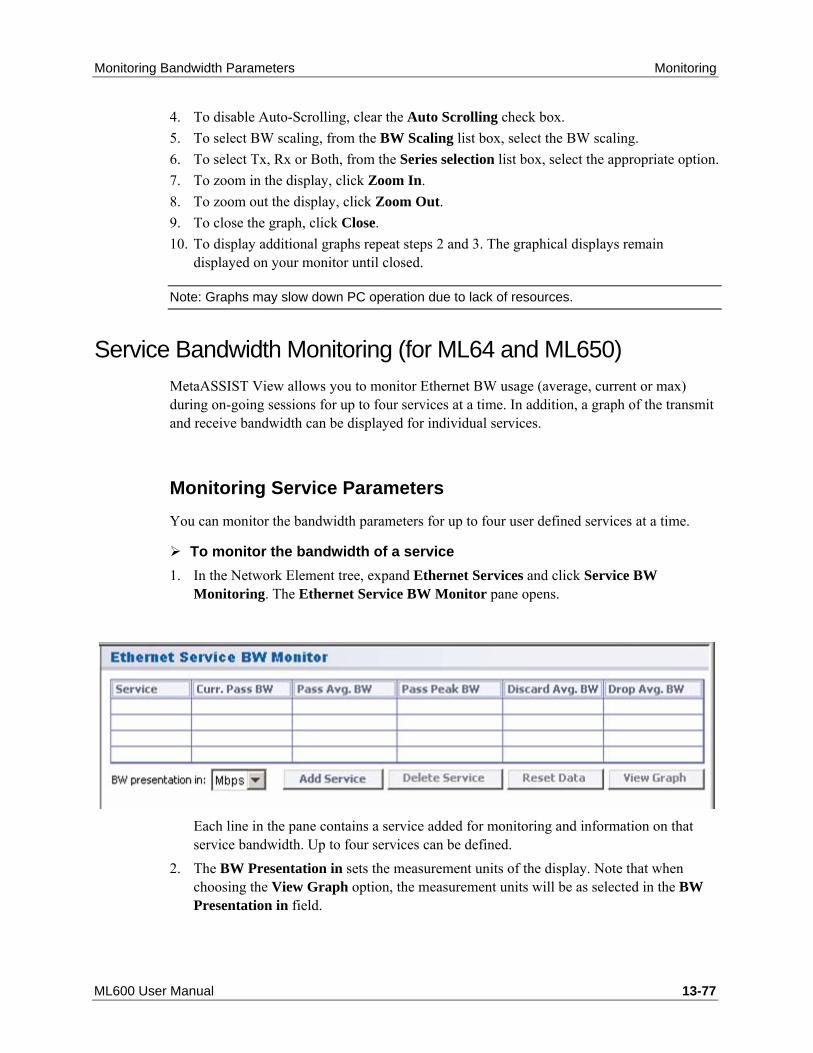
Monitoring Bandwidth Parameters Monitoring
ML600 User Manual 13-77
4. To disable Auto-Scrolling, clear the Auto Scrolling check box. 5. To select BW scaling, from the BW Scaling list box, select the BW scaling. 6. To select Tx, Rx or Both, from the Series selection list box, select the appropriate option. 7. To zoom in the display, click Zoom In. 8. To zoom out the display, click Zoom Out. 9. To close the graph, click Close. 10. To display additional graphs repeat steps 2 and 3. The graphical displays remain
displayed on your monitor until closed.
Note: Graphs may slow down PC operation due to lack of resources.
Service Bandwidth Monitoring (for ML64 and ML650) MetaASSIST View allows you to monitor Ethernet BW usage (average, current or max) during on-going sessions for up to four services at a time. In addition, a graph of the transmit and receive bandwidth can be displayed for individual services.
Monitoring Service Parameters You can monitor the bandwidth parameters for up to four user defined services at a time.
To monitor the bandwidth of a service 1. In the Network Element tree, expand Ethernet Services and click Service BW
Monitoring. The Ethernet Service BW Monitor pane opens.
Each line in the pane contains a service added for monitoring and information on that service bandwidth. Up to four services can be defined.
2. The BW Presentation in sets the measurement units of the display. Note that when choosing the View Graph option, the measurement units will be as selected in the BW Presentation in field.

Monitoring Monitoring Bandwidth Parameters
13-78 User Manual ML600
3. To add a service to the list:
• Click Add Service. The Add Service for BW Statistics dialog appears.
• From the list box, select the service and click OK.
• Repeat for additional services to be monitored. 4. You can also perform the following operations:
• Clear statistics on selected services - select the relevant services (more than one service may be selected at a time) and click Reset Data.
• Delete selected services from the list - select the relevant services (more than one service may be selected at a time) and click delete.
• View a graph of the average Tx and Rx bandwidth of a selected service - select the service and click Show Graph. Refer to Service Bandwidth Graph (on page 13-79).

Monitoring Bandwidth Parameters Monitoring
ML600 User Manual 13-79
Service Bandwidth Graph MetaASSIST View allows you to view a graphical representation of the Port traffic over time. You can view either the Tx and Rx or both concurrently on the same graph.
By default, the graph auto scrolls. You can disable the auto scroll by clearing the Auto Scrolling check box.
BW scaling can be modified via the Resolution list box with values of 100Kbps, 1 Mbps, 10 Mbps, 100 Mbps and 1 Gbps.
The window size in seconds or minutes is always displayed.
You can zoom in and zoom out of the display.
To display the graph: 1. In the Network Element tree, open Ethernet Services, Service BW Monitor. The
Service BW Monitor pane opens.

Monitoring Monitoring Bandwidth Parameters
13-80 User Manual ML600
2. On the table, select a row. Click Show Graph. The BW Monitor for <Port> dialog appears.
3. To disable Auto-Scrolling, clear the Auto Scrolling check box. 4. To select BW scaling, from the Resolution list box, select the BW scaling. 5. To select Tx, Rx or Both, from the Series selection list box, select the appropriate option. 6. To zoom in the display, click Zoom In. 7. To zoom out the display, click Zoom Out. 8. To close the graph, click Close. 9. To display additional graphs repeat steps 2 and 3. The graphical displays remain
displayed on your monitor until closed.
Note: Graphs may slow down PC operation due to lack of resources.

Service Connectivity Monitoring Monitoring
ML600 User Manual 13-81
Service Connectivity Monitoring The Ethernet Connection pane enables service providers to verify connectivity, monitor traffic flow and view the relevant configuration options on a defined link between two devices or on a single interface. The information is displayed in an intuitive, graphical pane: as a selection criterion is chosen, the pane automatically displays all relevant connection points and EVC information. For each selected link or interface, the following information can be displayed and analyzed:
• Port configuration
• Bridge and link configuration and status parameters
• Traffic statistics in each direction on the link
• Information on the VLANs, EVC configuration and EVC statistics
To invoke and navigate the Ethernet Connectivity tab
In the Main window, click the Connectivity tab and click Ethernet Connection. The Ethernet Connections pane is invoked.
The pane is divided into the following areas:
• NE 1 and NE 2 - shows the NEs whose interfaces or interconnection is to be analyzed. For each NE, the IP, VLANs and interfaces are displayed. The display is affected by the setting of the Automatic Link option.

Monitoring Service Connectivity Monitoring
13-82 User Manual ML600
• Automatic Link - This option is ENABLED by default - selecting any item (IP address, VLAN or Port), automatically displays all the associated items on both NEs. If Automatic Link is DISABLED, each item stands on its own. If it is modified, the associated items do not change accordingly. This enables analyzing each element on its own.
• Tabs at the bottom of the pane provide a range of detailed analysis options.
Table 61: Ethernet Connectivity Tabs
Tab Description
Port Shows the configuration and status of an individual interface or two interfaces comprising a link (according to the selected option and whether Automatic Link is enabled)
Bridge Shows Bridge level configuration and status for each of the defined NEs Ethernet Statistics Shows traffic flow on the link or on a single interface in the selected directionVLANs Shows the Port Membership and Tag for each VID, for each displayed NE EVC Shows the configuration for selected EVC EVC Statistics Quantifies various statistics for selected EVC. Selected statistics can be
displayed as graphs.
To analyze a link 1. The link of interest can be selected using two methods:
• From the Physical tab - Network Element tree, expand the Ethernet Port item and choose the relevant port. For example, HSL-1 or ETH-2. Select the Connectivity tab. The selected interface will be displayed along with any other interfaces and the VLANs relevant to the link.
• From the Connectivity tab:
o Under the relevant NE, select the HSL or ETH interface, the corresponding information will be invoked.
o Under Automatic Link - choose the relevant EVC. The corresponding connections will be displayed in the NE pane areas.
2. The above figure shows an end-to-end link connection between HSL-1 on the ML2300 DSDU-1 (lower SDU card) and HSL-1 on the ML624. The service is defined by VLAN 100.
3. Click the relevant tab to show the required link information.

Ethernet Topology Monitoring Monitoring
ML600 User Manual 13-83
Ethernet Topology Monitoring If the LLDP option is locally enabled for all the NEs participating in the Ethernet Topology, each NE is capable of discovering the other attached NEs and display each NE self-advertised information in the NEs linked via Ethernet pane in a tabular form along with relevant information on each element. See LLDP Configuration for a description on how to enable LLDP (LLDP disabled by default).
To display a list of the NEs linked via Ethernet
In the Network Element tree, select NEs Linked via Ethernet. The corresponding pane listing the NEs linked via Ethernet appears.
The parameters describing each NE Ethernet port link are listed in the table following the figure.
Note: The Details button is useful for non-Actelis vendors, where LLDP messages include extra-parameters (all mandatory parameters are represented in the table). MAV lists the HEX values of optional TLV (type-length-value) parameters, sent in LLDP.
Table 62: LLDP Parameters
Parameter Description
AID Port Identification on an NE which is directly connected via MAV.
Port ID (and Port ID type) Port Identification on an attached NE as discovered by LLDP: • For ML NE - Port Type is LOCAL name • On another device it can be set as SNMP IfTable Index,
IfEntity Index, etc. The type of presentation is determined on the attached NE.

Monitoring Ethernet Topology Monitoring
13-84 User Manual ML600
Chassis ID (and Chassis Type)
NE identification of the attached NE as discovered by LLDP: • For ML NE - Chassis ID is represented by its' Network
Address (IPv4) • On any other device it can be set as: Local name, SNMP
SysName, etc. System Name NE name of the attached NE, ML NE provides TID/SID of
the system. Enterprise The unique SNMP identification of Equipment Vendor.
Actelis Networks Enterprise OID = 5468.

DSx1 and Clock Monitoring Tools Monitoring
ML600 User Manual 13-85
DSx1 and Clock Monitoring Tools
Comparing DSx1 Parameters on Peers The DSx1 Connection pane is used to compare configuration and status information of an ML650 unit and its peer. It can be used for troubleshooting and to verify that the configuration parameters on the two units are compatible.
To access the DSx1 Connection tab
In the MetaASSIST View Main window, click the Connectivity tab and choose DSx1 Connection. The appropriate pane is invoked.
The pane contains two main areas: The top area showing the selected ML650 device and corresponding peer (i.e. CO and CPE), and the bottom area that provides information on the status and configuration of the corresponding ML650 device (above it in the same column).
Two Tabs are available on the bottom of the pane:
• System/Clock tab - shows the DSx1 Type, CES and Clock configurations on a defined link between two devices.
• Ports tab - shows DSx1 port configuration and status on a defined link between two devices

Monitoring DSx1 and Clock Monitoring Tools
13-86 User Manual ML600
The configurations of the two chosen units (CO and CPE) should match under the following parameters:
• DSx1 Type, CES Payload and CES Jitter Buffer size shall match on CO and CPE (separately configured per NE)
• Framing Type (separately configured per port of NE) shall match on CO and CPE DSx1 port of the same number (For example, DSx1-1-3 on CO and DSx1-1-3 on CPE)
• Channels (separately configured per port of NE) shall match on CO and CPE DSx1 port of the same number (DSx1-1-2 on CO and DSx1-1-2 on CPE)
• State of DSx1 port shall be enabled on both CO and CPE for the port of the same number (DSx1-1-4 on CO and DSx1-1-4 on CPE)
• All other mismatches are possible and should not affect the service.
To define an Identification Rule
• In the Network Topology tree, under Ethernet Services, select Identification Rules. The Frame Identification Rules pane appears. In example below ML650 rules are shown:

DSx1 and Clock Monitoring Tools Monitoring
ML600 User Manual 13-87
DSx1 Loopback The DSx1 loopback test is used to assist in fault isolation. During the loopback test, the external equipment (third-party equipment) connected to ML DSx1 ports analyzes the traffic BER (Bit Error Rate).
Two types of tests can be run: Facility and Equipment loopback. The tests can be run from either the CO side or from the CPE side. Usually, this test is initiated from the CO side and if required, is also performed from the CPE side.
Note: Clock flow is always from the CO side to CPE side, even if loopback is initiated from the CPE. See Clock Considerations (on page 13-88) for more information.
• Facility loopback mode - The loopback is in the DSX port entry towards the line and eliminates (except for rare cases of LIU failure) the ML as the root cause (i.e. the root cause is at the DSX source or between the DSX source and the ML unit).
• Equipment loopback mode - The loopback is in the far ML unit equipment towards the
near ML unit and eliminates (except for rare cases of LIU failure) the whole ML link (both CO and CPE sides) as the root cause (i.e. the root cause is at the DSX termination equipment at CPE side or between the DSX termination equipment and the ML unit).

Monitoring DSx1 and Clock Monitoring Tools
13-88 User Manual ML600
Clock Considerations
Note: Clock flow is always from the CO side to CPE side, even if loopback is initiated from the CPE.
During loopback, the CO side shall either get a clock from the external DSx1 equipment or be configured for internal free-run clock if external DSx1 equipment is configured to retrieve clock from line (not internal clock). DSx1 equipment shall always retrieve clock from the line (and not internal timing), even in case of loopback initiated from CPE side.
Configuring the DSx1 Port for Loopback
To configure the DSx1 Port for Facility or Equipment Loopback mode 1. In the Network Element tree, under TDM choose DSx1 Ports, click the DSx1 port to be
tested. 2. In the invoked pane, in the Configuration area, click Suspend. The port will be placed
in Maintenance mode and the appropriate icon will be displayed adjacent to the port item in the tree.
Note: Service is NOT disrupted.

DSx1 and Clock Monitoring Tools Monitoring
ML600 User Manual 13-89
In the Details area, the Loopback button will become available (this is true only after the port has been suspended).
3. Click the Loopback button. The following dialog appears.
4. Select Line (Facility) or Inward (Equipment) according to the required loopback mode.

Monitoring CFM MEP Monitoring Tools
13-90 User Manual ML600
CFM MEP Monitoring Tools ML devices support several EFM mechanisms used for locating the source and cause of network failures. These mechanisms operate using the capabilities provided by VLAN endpoints configured as MEPs (on page 10-15) (required part of the provisioning procedure). MEPs are able to originate ping (loopback) trace packets, and support continuity-check and cross-check functionalities. These Layer-2 mechanisms are used for troubleshooting faults of a customer service level.
The continuity-check mechanism (on page 13-92) can be used to determine which EVCs are impacted so the service provider can identify the downed customer services. The operator can verify the loss of connectivity using CFM loopback (on page 13-93) (ping), and locate the connection failure using CFM link trace (on page 13-96). The problem can then be further diagnosed and remedied. Finally, CFM loopback may be used to verify that the remedial action has succeeded and that the service has been re-established.
The test options are available on the MEP Pane (on page 13-91).

CFM MEP Monitoring Tools Monitoring
ML600 User Manual 13-91
MEP Pane The MEP pane provides general information and options relevant for the selected MEP. These include MEP configuration and suspend options, alarm configuration options, as well as display and MEP monitoring and test options that are described in this section.
To invoke the MEP Pane
In the Connectivity tab, under CFM, select the relevant MEP. The MEP pane is invoked.
At the bottom of the pane, under Remote MEPs (RMEP), a list of up to five remote MEPs (in the MA) is displayed. Basic information on each MEP is provided in the displayed table.
Note: For more information on a MEP in the list, select the MEP row and click the Details button.
Table 63: Navigating the MEP Dialog
Click... To...
RMEP Details Show more information on a selected RMEP. Init RMEP Refresh the RMEP discovery process. Loopback Ping a selected RMEP according to the parameters defined in the
invoked dialog.

Monitoring CFM MEP Monitoring Tools
13-92 User Manual ML600
Link Trace Trace the path to a selected RMEP according to the parameters defined in the invoked dialog.
Topology Visually display of the connectivity of a service defined according to the NEs, HSLs and VLANs that determine the service link.
MEP Topology The MEP Topology provides a visual display of a defined link: as one interface point is selected, the pane automatically displays the peer connection, relevant VLAN, relevant HSL and services side (Ethernet) interfaces.
To invoke the MEP Topology display 1. From Connectivity tab, under CFM, select the relevant MEP. 2. In the invoked pane, click the Topology button at the bottom of the pane.
The display shows the elements on either side of a link:
• Select one of the NEs comprising the link (i.e. DSDU-1 or CPE1-624) to view the relevant VLANs, Ports and HSLs for each NE.
• Select a VLAN for an NE. If Automatic Link (at the top of the tab) is enabled, the same VLAN on the other side of the link (other NE) will be displayed along with the relevant ports and HSLs for each NE.

CFM MEP Monitoring Tools Monitoring
ML600 User Manual 13-93
CFM Loopback CFM loopback can be used by the operator to verify connectivity (ping). The test consists of Unicast frames transmitted by a MEP at administrator request to verify connectivity to a particular maintenance point, indicating if a destination is reachable.
A CFM loopback message is similar to an Internet Control Message Protocol (ICMP) ping message; however, the CFM loopback message cannot pass through L3 switching (Routers) devices, making the operation relevant only for L2 switching (Bridges) network.
Note: CFM loopback is dedicated for connectivity fault isolation and for SLA performance monitoring
The Waiting interval between two loopback messages transmitted in series is set to 1 sec and the timeout to report loopback failure is set to 5 sec. These options are not configurable. Other attributes such as number of messages sequentially sent, length of data, etc. are user configurable.
A total of 10 Loopback operations can be simultaneously executed from the same NE.
To configure and run CFM Loopback 1. In the Connectivity tab, under the relevant MA, select the MEP to be analyzed. The
corresponding pane is invoked.

Monitoring CFM MEP Monitoring Tools
13-94 User Manual ML600
2. Under Remote MEPs (RMEP), select Loopback.The following dialog appears.
3. Set the MAC address to which the loopback will be performed - this is the unicast
address of the remote device. Set the address using one of the following options:
• Remote MAC Address - type the address
• Remote MEP - select from the list of addresses discovered during CCM remote MEP. 4. Define the attributes of the data to be sent:
• Number of messages to send - number of CFM LPBK frames to be sent in series. Range 1 to 100
• Data length - CFM Loopback Message Frame Payload (without CFM header). Range 1 to 1500

CFM MEP Monitoring Tools Monitoring
ML600 User Manual 13-95
• Priority - L2 COS bits of CFM LPBK frame to send. Range 0 to 8
• Sequence ID - number applied to each CFM LPBK frame. Uniquely identifies the series.
Note: Click Clear to clear the configured definitions.
5. Click Send. If connectivity is available (at some level), the returned message will be displayed. The quality of the message can be induced from the response.
Table 64: Loopback Tab buttons
Click... To...
Clear clear currently displayed data. Save As... save the test results to a user defined text file Stop stop the test Close close the tab

Monitoring CFM MEP Monitoring Tools
13-96 User Manual ML600
CFM Link Trace Link trace is used to locate a connection failure by following a path (tracing a link) between the local MEP and a destination (MEP or any other Unicast destination). This is implemented by the CFM link trace message - a multicast message which requests all CFM domain participants to respond and forward (re-build) the request. The report used for analyzing the connectivity for the path includes: a list of all the domains through which a message would need to pass, along with their current status, link type, address, etc.
Timeout of error messages is not displayed; the successful result should be found manually by analyzing the Terminal MEP = MEP and Rx Flag = 0 (which means the MEP destination was achieved) or by Rx Flag = 0 only (which means the addressed MIP destination was achieved).
CFM Link Trace requests/responses by ML NE are forwarded only through the active topology (on ETH ports which are considered as Traffic Forwarding by STP/RSTP, when enabled).
Note that:
• Only MIP and MEP objects participate. The regular ETH port on NE will not respond to the CFM Link Trace Message.
• CFM message is terminated (dropped) on an NE if the CFM level defined in a message is lower than the CFM level defined for the NE. For example, CFM domain of level=4 will answer/forward messages of level 4,5,6,7, and drop 1,2,3 – as appeared out of boundaries of allowed CFM domain.

CFM MEP Monitoring Tools Monitoring
ML600 User Manual 13-97
Note: The display can be saved to a text file.
To run link trace between two MEPs 1. In the Connectivity tab, under the relevant MA, select the MEP to be analyzed. The
corresponding pane is invoked.

Monitoring CFM MEP Monitoring Tools
13-98 User Manual ML600
2. Under Remote MEPs (RMEP), select Link Trace. The following dialog appears.
3. Set the MAC address (unicast address) of the remote device to which the link trace will
be performed, using one of the following methods:
• Remote MAC Address - type the address
• Remote MEP - select from the list of addresses 4. Define the attributes of the data to be sent:
• Timeout - Number of seconds before the Link Trace request is transmitted.
• TTL (Time To Live) – Period of time a data unit can exist in the network. Used to prevent packets that have not reached their destination from loading the network.
• Sequence ID – user defined ID assigned to the link trace sequence. Used to identify and analyze the link trace messages.
• Egress ID – after the test is run, shows the ID of the port on which the link trace packet egressed.
• Time Stamp – Index showing when the Link Trace test was run (shown after the test is run).
5. Click Send. If connectivity is available (at some level), the returned message will be displayed.

CFM MEP Monitoring Tools Monitoring
ML600 User Manual 13-99
The message (e.g. illustrated below) shows the Seq ID (i.e. 5), other configured parameters (i.e. TTL = 64) and link trace information.
Note: Use the scroll bar at the bottom of the window to show display additional information.
For more explanations about the messages in this window, see Link Trace Result Example (on page 13-100).
The Link Trace tab buttons can be used to control the test and save results:
Table 65: Link Trace Tab buttons
Click... To...
Save As... save the test results to a user defined text file Stop stop the test Close close the tab
Each CFM Link Trace response includes the following information.
Table 66: CFM Link Trace Response Information
Message Info Description
Seq ID Sequence ID. The identification which communicates Link Trace Request and Response messages (the ID is equal). This identification is used to identify own Link Trace Request (and it’s responses) in multiple management environment.
TTL Time-to-live. Provided in Link Trace Request/Response Message. Each NE answering to the CFM Link Trace message, decreases (-1) the TTL forwarded in the CFM Link trace Request. This is used to identify the number of hops that participated in the link trace.
Rx Flag Shows if CFM Link Trace message was re-build and forwarded.

Monitoring CFM MEP Monitoring Tools
13-100 User Manual ML600
Terminal MEP Identifies the responder as a MIP (intermediate point) or MEP (end point)
Egress ID and Next Egress ID
Re-built by each hop when the CFM Link trace message is re-sent. Used view directly communicating hops (as chain): • Two NEs are considered as connected if Next Egress ID of one of
them appears as (Last) Ingress ID on another (see example). • Egress ID format includes: Shared MAC (of Bridge) provided in the
low-order six octets, and internally used (MEP + PORT) unique NE identification in the high-order two octets.
Relay Specifies which forwarding table is used (MIP/MEP FRWDB or Traffic FRWDB). On ML NE only MIP/MEP FRWDB is used for CFM forwarding.
CHS ID Type, CHS ID, Mang.Address
Identifies NE (chassis) type, TID/SID configured on ML NE, and NE Management Address (IP V4 format)
Ingress, Ingress MAC, Ingress Port ID
Reports Ingress Port Status, Address and Local Name of the Port on which the CFM Linktrace Request message was received (come in). Note: CFM Link Trace Response is sent backward through the port specified as ingress.
Egress, Egress MAC, Egress Port ID
Reports Egress Port Status, Address and Local Name of the Port on which the CFM Linktrace Request message was forwarded (come out).
ORG TLV Organization Specific TLV. ML NE doesn't provide this parameter. If any other device will provide, ML will print out this parameter in HEX form.
Link Trace Result Example In this example you can see a fragment of CFM Linktrace response collected in Link Trace dialog:

CFM MEP Monitoring Tools Monitoring
ML600 User Manual 13-101
By scrolling the pane to the right, this text is revealed:
1st line: Seq Id = 1, TTL = 64, RX Flag = 1, Terminal MEP = No,
Egress ID = 01-92-00-03-85-00-8D-C9, Next Egress ID = 00-05-00-03-85-00-28-C6, Relay = MIP Forward DB,
CHS ID Type = ENTPHNAME, CHS ID = Z0525G40008, Mang. Addr = 10.1.4.1 (IPV4), Ingress = Ok, Ingress MAC = 00-03-85-00-28-C6, Ingress Port ID = ETH-6 (LOCAL), Egress = Ok, Egress MAC = 00-03-85-00-28-C6, Egress Port ID = ETH-4 (LOCAL), ORG TLV = null
2nd line: Seq Id = 1, TTL = 63, RX Flag = 1, Terminal MEP = No, Egress ID = 00-05-00-03-85-00-28-C6, Next Egress ID = 00-03-00-03-85-01-5D-CA, Relay = MIP Forward DB, CHS ID Type = ENTPHNAME, CHS ID = ML648-64, Mang. Addr = 10.1.6.7 (IPV4), Ingress = Ok, Ingress MAC = 00-03-85-01-5D-CA, Ingress Port ID = ETH-4 (LOCAL), Egress = Ok, Egress MAC = 00-03-85-01-5D-CA, Egress Port ID = ETH-2 (LOCAL), ORG TLV = null
3rd line: Seq Id = 1, TTL = 62, RX Flag = 1, Terminal MEP = No, Egress ID = 00-03-00-03-85-01-5D-CA, Next Egress ID = 00-09-00-03-85-01-5D-B6, Relay = MIP Forward DB, CHS ID Type = ENTPHNAME, CHS ID = ML648-CO, Mang. Addr = 10.1.6.15 (IPV4), Ingress = Ok, Ingress MAC = 00-03-85-01-5D-B6, Ingress Port ID = ETH-2 (LOCAL), Egress = Ok, Egress MAC = 00-03-85-01-5D-B6, Egress Port ID = HSL-1 (LOCAL),
ORG TLV = null
Explanation:
In this fragment CFM Link Trace Request passed through NE with TID="Z0525G40008", then through NE with TID="ML648-64" and then through NE with TID="ML648-CO".
It is clear that this is a "chain" connectivity (and not "star"): The Next Egress ID=00-05-00-03-85-00-28-C6 of 1st response (first line) is equal to Egress ID=00-05-00-03-85-00-28-C6 from 2nd response (2nd line) and Next Egress ID=00-03-00-03-85-01-5D-CA from 2nd response is equal to Egress ID=00-03-00-03-85-01-5D-CA from 3rd response (3rd).


ML600 User Manual 14-1
ML products perform an extensive Self-test during power up, checking the installed hardware, data paths and system configuration. In addition, an in-service diagnostic test is periodically performed during normal operation, ensuring system sanity. In case of an alarmed condition, an indication of the event is given through:
- Front panel LEDs
- Office alarms transmitted via the alarm relays
- Autonomous TL1 reports, alarms and non-alarmed conditions
- SNMP traps
For more information or if you are unable to resolve a problem using these procedures, contact Actelis Networks customer support. mail to:[email protected] ([email protected]).
In This Chapter
Recommended Test Equipment.................................. 14-2 Power On Faults.......................................................... 14-3 LED Fault Indications .................................................. 14-4 Dry Contact Alarm Indications..................................... 14-7 Alarmed Conditions ..................................................... 14-8 Copper Lines Troubleshooting .................................. 14-29 Ethernet Service Troubleshooting ............................. 14-81 Management Connection Problems .......................... 14-95 Resolving Management Connection Problems ....... 14-100 Resolving Configuration Considerations Due to Dipswitch Settings 14-105
. 14 14 Troubleshooting

Troubleshooting Recommended Test Equipment
14-2 User Manual ML600
Recommended Test Equipment To ensure successful troubleshooting of the ML device, the following test equipment is recommended:
• PC with MetaASSIST View
• Line test equipment, such as HP Transmission Impairment Measurement Set (HP TIMS), for testing the copper pairs if required
• DVM for measuring the power supply voltages

Power On Faults Troubleshooting
ML600 User Manual 14-3
Power On Faults
No Power Indication Symptom: All front panel LEDs are off.
Corrective action: Check the following:
• Check DC input voltage (-40 VDC to -72 VDC);
• If there is no DC and AC adapter is used, check if the AC adapter is properly connected to the AC supply;
• If the problem is not resolved, replace the AC adapter;
• If the problem is not resolved, replace the ML device unit.
ML600 Does Not Start Initialization Symptom: The STATUS LED is in one of the following states:
• Remains red for more than 15 seconds after Power On/Reset;
• Blinking green and does not become steady green.
Corrective action: Replace the ML600.

Troubleshooting LED Fault Indications
14-4 User Manual ML600
LED Fault Indications ML600 Models do not contain any user replaceable parts. Any hardware faults on the ML600 models require the unit to be replaced. Faults due to incorrect facility connections can be detected and corrected.
The following figure shows the front panel of ML650 model (that also support T1/E1 service ports):
Figure 29: ML650 Location of LEDs
The following table summarizes the normal and faulty system LED indications.
Table 67: Front Panel LEDs
LED Status Recommended Responses Power ON - Normal. Power input OK. --
OFF - Faulty power input. 1. Check if power is correctly supplied to the ML. 2. If ed by AC Adapter and no power at the input of the ML unit, replace the AC adapter. 3. If unresolved, replace the ML600
Status Indicates general status of unit. GREEN - Steady. Normal. No hardware errors.
--
GREEN - Blinking. Initialization in progress. Wait for Power on sequence completion. If blinking continues for more than 10 minutes, replace the ML600.
RED - Hardware error detected. Replace the ML600.

LED Fault Indications Troubleshooting
ML600 User Manual 14-5
Alarm Indicates alarm on head-end or one of the remote units. OFF - Normal condition. No alarm is detected.
--
YELLOW - Minor alarm indication. RED - Major alarm indication.
Faulty. See Troubleshooting Alarmed Conditions (on page 14-8).
LNK (ETH port)
Link status: up or down. GREEN - Steady (Normal state), Link up and not blocked by STP.
--
YELLOW - Steady. Link up and blocked by STP Check for redundant Ethernet routes YELLOW - Blinking. HSL only. HSL calibration or
recovery in progress. Wait for HSL calibration or recovery termination. If calibration or recovery fail, refer to Troubleshooting Alarmed Conditions (on page 14-8).
OFF - Normal if link is down, or port is disabled. - Otherwise, refer to recommended actions.
If Normal conditions are not relevant, check the following: 1. Port configuration. 2. Verify that the Port is not administratively removed from service (by disable or suspend operations). 3. Ethernet cables. 4. That external switching equipment is on.
ACT Link activity (sending or receiving frames) state. An ACT indicator is provided for each of the Ethernet and HSL ports. GREEN - Blinking (Normal). Data activity
--
OFF - SW initialization in progress - Port is idle (no data transmission) - Port is disabled
Check if external switching equipment is on; Check if port was administratively removed from service.
MLP Synchronization status of corresponding modem. GREEN - Steady (Normal). Modem is synchronized. OFF - Corresponding modem not in use - Configuration or signal loss.
If the modem is in use, then verify that it was not deleted in the head-end unit or is disconnected(copper loop connections).
BLINKING - Modem is attempting to synchronize.
Wait for MLP synchronization, typically 1 minute. If HSL is up, and the modem failed, e.g. the line has been permanently cut (also alarmed). The LED will blink until the line is repaired.

Troubleshooting LED Fault Indications
14-6 User Manual ML600
LNK (DSx1 port)
Available only on ML650 models. Bi-color (green/yellow) color LED (on the right) per each T1/E1 port. Note: The LED is integrated into the RJ45 connector and behave as the following: • Off- port is disabled • Green Solid - port is enabled • Yellow Solid - Loop Test (both directions:
equipment and facility loopback)
ERR (DSx1 port)
Available only on ML65x models. Red color led (on the left) per each T1/E1 port. Note: The LED is integrated into the RJ45 connector and behave as the following: • Off - no alarm conditions • Red blinking slow– AIS is received • Red blinking fast – AIS is transmitted (or both,
transmitted and received) • Red solid – LOS/LOF
For LOS, LOF, AIS alarms correction see Troubleshooting chapter.

Dry Contact Alarm Indications Troubleshooting
ML600 User Manual 14-7
Dry Contact Alarm Indications • Critical or Major fault (including power input failure) activates (closes) the
corresponding alarm output of the ML600 device.
• PFU HW fault (including power input failure) activates (closes) the PFU alarm output.
• PFU port faults (e.g. over current, voltage limit) do not cause PFU's dry-contact alarm output to activate. PFU port faults can be seen in the PFU pane (on page 13-15), Topology pane (on page 13-45) and Topology Test pane (on page 14-53).

Troubleshooting Alarmed Conditions
14-8 User Manual ML600
Alarmed Conditions
Troubleshooting Workflow When an alarm condition occurs, one of the system front panel Critical, Major or Minor alarms LEDs lights up according to the highest alarm severity that presently exists in the system. The condition is also indicated on the MetaASSIST View system pane, see the following figure.
To troubleshoot the alarm using MetaASSIST View: 1. As illustrated in the following figure, in the system alarms and conditions table (at the
bottom of the window), double-click the alarm (any where in the row). As a result:
• The pane corresponding to the selected component is invoked. The pane provides detailed information on the item.
• The relevant item is indicated in the Network Element tree. 2. Follow the troubleshooting procedures described in the troubleshooting tables.

Alarmed Conditions Troubleshooting
ML600 User Manual 14-9
Field Descriptions The following table provides the field descriptions for the alarms and conditions table for both the system pane and component pane.
Table 68: Field descriptions for alarms and conditions table
Field Name This field provides ...
Severity The Notification code of the alarm or message and the MTTR (Mean Time To Repair) requirement according to GR-474-CORE is as follows: • CR—Critical - 45 minutes MTTR; • MJ—Major - 90 minutes MTTR; • MN—Minor - 120 minutes MTTR; • NA—Not Alarmed; • NR—Not Reported.
For additional details on notification codes, see About Alarm Severity and Conditions (on page 13-7).
Note: NA and NR are not displayed in MetaASSIST View unless their status is change to CR, MJ or MN.
Condition Type
The condition that caused the alarm or message. As will be explained later in this section, the Condition Type field plays a key role in determining the troubleshooting procedures.
AID The Access Identifier of the component (entity) involved with the alarm or message. The components can be one or more of the following: • System: COM; • Equipment: ML600; • Ethernet ports: ETH-{1-5}, COLAN (MGMT); • High Speed Links: HSL-1/2; • Modem Line Ports: MLP-1-{1-8}; • Environmental Alarm Input: EC-1/2; • External Controls: CC-1.
SA/NSA The effect that reported event has on system operations. Possible values are: • SA means event is Service Affecting (i.e., it caused part or all traffic to be dropped);• NSA means event is Not Service Affecting (e.g., redundant power input failure).
Time The date-and-time when the event occurred. Date format is MM-DD; Time format is HH-MM-SS.
Description Text description of the event.

Troubleshooting Alarmed Conditions
14-10 User Manual ML600
Field Name This field provides ...
Location (Loc.)
The event location. Possible values are: • NEND - (Near End), the problem is in the monitored ML device; • FEND - (Far End), the problem is in the external system attached to the monitored
ML device; • BOTH - the problem is both in the monitored ML device and in the external system
attached to the monitored ML device. Direction (Dir.)
The direction related to the event. Possible values are: • TRMT — the component was transmitting; • RCV — the component was receiving; • BTH — the component was transmitting and receiving; • NA — Not Applicable.
Alarmed Conditions Tables The troubleshooting procedures are described in the following tables. They include troubleshooting:
• System (on page 14-11);
• Equipment (on page 14-12);
• Modem Ports (on page 14-16);
• High Speed Link (on page 14-19);
• Service Port (on page 14-24).
Note: The severity of a condition type is user configurable. The severity of each condition type, mentioned in the following troubleshooting tables, is according to factory setup.

Alarmed Conditions Troubleshooting
ML600 User Manual 14-11
System Alarms Troubleshooting
Table 69: System troubleshooting table
Condition Type
Description Recommended Troubleshooting Procedure
NOSETUP No initial setup; System is in Factory setup. In addition to the date-and-time and the text for the alarm description, this report includes the following information: • AID is COM; • Default Severity is CR; • SA/NSA is SA; • Location is NEND; • Direction is NA.
Configure the system. The alarm is cleared immediately after the first configuration command. If you have a backup file of the configuration, reload the setup. See Reverting to Backup Software (on page 12-16). If the alarm is not cleared or reappears later on even if the system is configured, then this is probably due to a faulty unit. Replace the ML device unit.
UPGRDIP Software Upgrade in Progress; The alarm is raised when download of the new SW is initiated. In addition to the date and time and the text for the alarm description, this report includes the following information: • AID is COM; • Default Severity is NA; • SA/NSA is NSA; • Location is NEND; • Direction is NA.
Commit SW operation should be provided to clear the alarm. Commit SW operation is enabled regardless of new SW status. It is recommended to Activate new SW and ensure that Service is OK before Committing the new SW. Refer to Updating the System Software (on page 12-12) for details.

Troubleshooting Alarmed Conditions
14-12 User Manual ML600
Equipment Alarms Troubleshooting
Table 70: Equipment alarms troubleshooting table
Condition Type
Description Recommended Troubleshooting Procedure
HWFLT AID ML600
Hardware fault; Indicates a card failure. In addition to the date-and-time and the text for the alarm description, this report includes the following information: • AID is ML600; • Default Severity is CR; • SA/NSA is SA; • Location is NEND; • Direction is NA.
Replace ML600.
PROGFLT AID ML600
Program store failure; Software release in the ML device is corrupted and cannot be automatically repaired. On nearest reboot the system may crash. In addition to the date-and-time and the text for the alarm description, this report includes the following information: • AID is ML600; • Default Severity is CR; • SA/NSA is SA; • Location is NEND; • Direction is NA.
The corrupted file must be replaced as soon as possible (downloaded from a server) as follows:
1. View the software revision of the unit. In the Network Element tree, click System Administration, SW Release.
2. Download the correct software version. In the SW Release pane, perform all the Software Update procedures.
3. If problem is not resolved, replace ML600.

Alarmed Conditions Troubleshooting
ML600 User Manual 14-13
Condition Type
Description Recommended Troubleshooting Procedure
UEQ AID SFP
Unequipped module; The SFP module is configured but not present in its socket. Alarm is reported as Not Service Affecting (NSA) and Minor when Ethernet port associated with the SFP module is not part of any VLAN or this Ethernet port is either not enabled or removed from Service intentionally. Otherwise Alarm is reported as Service Affecting (SA) and Major. In addition to the date-and-time and the text for the alarm description, this report includes the following information: • AID is SFP-1-1; • Default Severity is MJ or MN; • SA/NSA may be SA or NSA; • Location is NEND; • Direction is NA.
Make sure specified module is installed properly. If necessary, replace the module.

Troubleshooting Alarmed Conditions
14-14 User Manual ML600
Condition Type
AID Description Recommended Troubleshooting Procedure
HWFLT SFP SFP hardware failure; Indicates that plugged-in SFP module is unreadable (either MSA non-compliant or faulty SFP module). Alarm is reported as Not Service Affecting (NSA) and Minor when Ethernet port associated with the SFP module is not part of any VLAN or this Ethernet port is either not enabled or removed from Service intentionally. In addition to the date-and-time and the text for the alarm description, this report includes the following information: • AID is SFP-1-1; • Default Severity is MN or
MJ; • SA/NSA: NSA or SA; • Location is NEND; • Direction is NA.
Perform one of the following: 1. Replace SFP module. 2. If problem is not resolved,
replace ML600.

Alarmed Conditions Troubleshooting
ML600 User Manual 14-15
Condition Type
AID Description Recommended Troubleshooting Procedure
UNKNOWN SFP SFP module of Unsupported SFP interface type is inserted (for supported types, see Pluggable Equipment Control (on page 4-9)). In this case service is blocked. Not listed in the Parts List SFP module, which is also non-compliant to Multiple Source Agreement (MSA), is inserted. Service is not blocked. Alarm is reported as Not Service Affecting (NSA) and Minor when Ethernet port associated with the SFP module is not part of any VLAN or this Ethernet port is either not enabled or removed from Service intentionally. Otherwise Alarm is reported as Service Affecting (SA) and Major. In addition to the date-and-time and the text for the alarm description, this report includes the following information: • AID is SFP-1-1; • Default Severity is MN; • SA/NSA: NSA; • Location is NEND; • Direction is NA.
If non-compliant to MSA SFP is in use, set the alarm to NA, see Modifying Alarm Severity. For Unsupported SFP type, replace with an appropriate SFP type module.
EOPTMIS SFP SFP module of inserted does not match the manual configuration of ETH-5 MODE (see Configuring Ethernet Ports (on page 4-39))
Check the ETH-5 port configuration and either replace the SFP module to match it or reconfigure ETH-5 port.
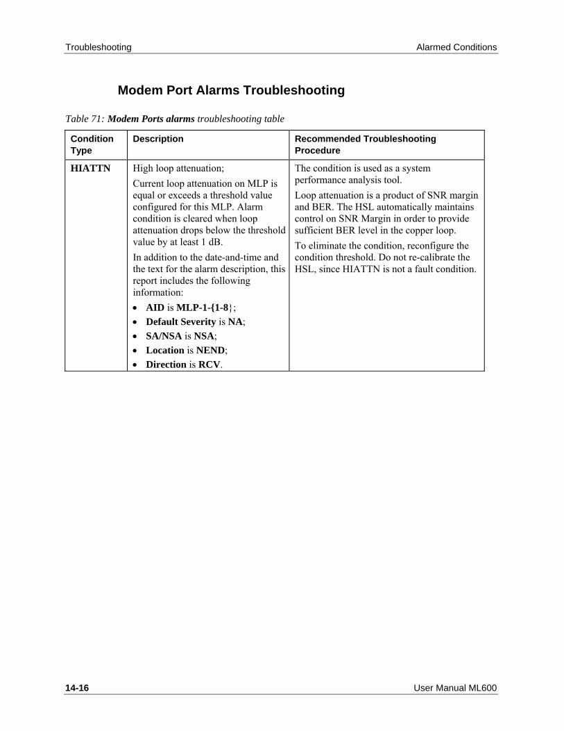
Troubleshooting Alarmed Conditions
14-16 User Manual ML600
Modem Port Alarms Troubleshooting
Table 71: Modem Ports alarms troubleshooting table
Condition Type
Description Recommended Troubleshooting Procedure
HIATTN High loop attenuation; Current loop attenuation on MLP is equal or exceeds a threshold value configured for this MLP. Alarm condition is cleared when loop attenuation drops below the threshold value by at least 1 dB. In addition to the date-and-time and the text for the alarm description, this report includes the following information: • AID is MLP-1-{1-8}; • Default Severity is NA; • SA/NSA is NSA; • Location is NEND; • Direction is RCV.
The condition is used as a system performance analysis tool. Loop attenuation is a product of SNR margin and BER. The HSL automatically maintains control on SNR Margin in order to provide sufficient BER level in the copper loop. To eliminate the condition, reconfigure the condition threshold. Do not re-calibrate the HSL, since HIATTN is not a fault condition.

Alarmed Conditions Troubleshooting
ML600 User Manual 14-17
Condition Type
Description Recommended Troubleshooting Procedure
LOSW Loss of Synchronization Word; The MLP has lost synchronization. This condition is MJ, SA if modem belong to the HSL with LOWBW Threshold Control enabled and crossed. The condition is applicable on HSL in -O (Office) mode only. In all other cases this condition is MN, NSA. In addition to the date-and-time and the text for the alarm description, this report includes the following information: • AID is MLP-1-{1-8}; • Default Severity is MN or MJ; • SA/NSA is NSA or SA; • Location is NEND, FEND,
LINE-2, LINE-4, LINE-6, LINE-8, ... LINE-16;
• Direction is RCV.
This problem is typically caused by temporary disturbances, such as micro-interruptions or transient noise. LOCN = LINE-2, 4, 6, 8, ...16 refers to repeated line termination point (Repeater Port) with probable failure (either in TX HW of last achievable repeater, in line toward STU-R, or on the RX HW of first non-achievable from STU-C site repeater). See Repeated Copper Lines Troubleshooting. To determine whether problem is temporary or persistent, perform the following:
1. In Modem Ports pane, click Details (All Modems) button. Details For Modem Ports pane opens.
2. Check the details for the specified MLP for the system.
If the problem is persistent, try the following procedures in the suggested order: • Follow the instructions in Analyzing
Results of the Line Qualification Routines (on page 14-36) to eliminate a modem mismatch as a possible cause.
• Check the copper pairs (lines). Repair/replace lines, as necessary; check out RJ-45 connectors.
!! When replacing pairs, be careful not to disconnect adjacent pairs.

Troubleshooting Alarmed Conditions
14-18 User Manual ML600
Condition Type
Description Recommended Troubleshooting Procedure
LOWSNRM Low SNR margin; Current SNR margin on MLP is equal or less than a threshold value configured for this MLP. Alarm condition is cleared when SNR margin returns to +1 dB above the threshold value. In addition to the date-and-time and the text for the alarm description, this report includes the following information: • AID is MLP-1-{1-8}; • Default Severity is NA; • SA/NSA is NSA; • Location is NEND; • Direction is RCV.
The condition is used as a system performance analysis tool. The HSL automatically maintains control on SNR Margin in order to provide sufficient BER level in the copper loop. To eliminate the condition, reconfigure the condition threshold. Do not re-calibrate the HSL, since LOWSNRM is not a fault condition.
QUALFLT Qualification fault; Modem failed qualification during calibration due to insufficient transmission rate, noise margin or excessive cross-talk. In addition to the date-and-time and the text for the message description, this report includes the following information: • AID is MLP-1-{1-8}; • Default Severity is MN; • SA/NSA is NSA; • Location is NEND; • Direction is RCV.
This condition is most likely caused by cut or bad lines. Perform the following procedures in the suggested order: • Analyze the qualification test routine
results.. • Use the procedures to check the copper
pairs (lines) for the MLPs specified by the QUALFLT alarm. Repair/replace lines, as necessary; check out RJ-45 connectors.
• ! When replacing pairs, be careful not to disconnect adjacent pairs.
• De-calibrate (Cancel Calibration) the HSL where MLPs belong.
• In Modem Ports pane, click Details (All Modems) button and determine MLPs are synchronized at minimum rate.
• In High Speed Link pane, click Calibrateto calibrate the HSL (allow a few minutes for downtime). Ensure that there are no QUALFLT modems.
• If you are sure about line quality, and QUALFLT still exists, replace the unit.

Alarmed Conditions Troubleshooting
ML600 User Manual 14-19
High Speed Link Alarms Troubleshooting
Table 72: HSL alarms troubleshooting table
Condition Type
Description Recommended Troubleshooting Procedure
COPPERMIS
Copper mismatch connection; There is no Ethernet service and in-band management traffic. Applicable on HSL configured in -O (Office) mode. In addition to the date-and-time and the text for the alarm description, this report includes the following information: • AID is: HSL-<ID>; • Default Severity is MJ; • SA/NSA is SA; • Location is NEND; • Direction is BTH.
The ML device with HSL in -O (Office) mode can detect and report that this HSL is terminated on multiple -R (Customer) destinations. The table in the Modem Ports pane provides unique identification (Serial Number) of each copper line termination. The table column - "Linked NE" provides Serial Number (s) of the discovered linked by HSL ML device system(s). To resolve the problem: • Re-connect each copper line with different
Serial Number discovered on distant end. MLP provides Serial Number discovery immediately after synchronization.
To work around the problem: • Reconfigure HSL on local side to exclude
incorrectly terminated copper lines from HSL. De-calibrate (Cancel Calibration) the HSL; then delete MLPs from HSL, re-calibrate HSL once more.

Troubleshooting Alarmed Conditions
14-20 User Manual ML600
Condition Type
Description Recommended Troubleshooting Procedure
HSLDIAG High Speed Link is Up, but not calibrated yet. Up, not calibrated status can appear when the system is powered for the first time or when you click the Cancel Calibration button in HSL pane. Applicable on HSL configured in -O (Office) mode. In addition to the date-and-time and the text for the alarm description, this report includes the following information: • AID is HSL-1; • Default Severity is NA; • SA/NSA is SA; • Location is NEND; • Direction is BTH.
In High Speed Link pane, click the Calibrate button to calibrate the HSL (allow a few minutes to complete the process).
HSLDWN HSL is down; Temporary alarm resulting from HSL initialization or recovery process (secondary state is HUNT, CALIB or RCVRY). Applicable on HSL configured in -O (Office) mode. In addition to the date-and-time and the text for the alarm description, this report includes the following information: • AID is HSL-1; • Default Severity is MJ; • SA/NSA is SA; • Location is NEND; • Direction is BTH.
There is a temporary alarm. Verify in the HSL pane, Details section, that after a few minutes the HSL status is changed to one of the following: • UP with the appropriate alarm or no
alarms; • HSLDIAG with the appropriate alarm; • HSLFLT with the appropriate alarm. If problem is not resolved, check if linked by HSL ML device is powered up, correctly installed (copper loop connections), not alarmed and MLP and HSL are configured properly.

Alarmed Conditions Troubleshooting
ML600 User Manual 14-21
Condition Type
Description Recommended Troubleshooting Procedure
HSLFLT HSL is faulty; High Speed Link has failed and cannot be recovered automatically due to one of the following: • The copper pairs are
disconnected; • Linked by HSL Actelis system is
faulty. Applicable on HSL configured in -O (Office) mode. In addition to the date-and-time and the text for the alarm description, this report includes the following information: • AID is HSL-1; • Default Severity is CR; • SA/NSA is SA; • Location is NEND; • Direction is BTH.
• Check the copper pairs connection. See the table (on page 14-36) for possible causes;
• If problem is not resolved, check if linked by HSL ML device is powered up, correctly installed (copper loop connections), not alarmed and MLP and HSL are configured properly;
• If problem is not resolved, replace linked ML device.
LOWBW Configured HSL BW Threshold is crossed. By factory default, HSL BW threshold is disabled. Applicable on HSL configured in -O (Office) mode. In addition to the date-and-time and the text for the alarm description, this report includes the following information: • AID is HSL-1; • Default Severity is NA; • SA/NSA is SA; • Location is NEND; • Direction is BTH.
To avoid LOWBW alarm: Disable Threshold control or reduce Threshold value in accordance with available HSL BW. To resolve insufficient available HSL BW, troubleshoot Modem Ports (repair/replace/add) and then re-calibrate HSL.

Troubleshooting Alarmed Conditions
14-22 User Manual ML600
Condition Type
Description Recommended Troubleshooting Procedure
PLANFLT Planning fault; HSL Planning Failure - High Speed Link cannot provide the requested target bandwidth. Applicable on HSL configured in -O (Office) mode. In addition to the date-and-time and the text for the alarm description, this report includes the following information: • AID is HSL-1; • Default Severity is CR; • SA/NSA is SA; • Location is NEND; • Direction is BTH.
Perform the following procedures in the suggested order:
1. In HSL pane, determine the available bandwidth.
2. Try the following procedures in the suggested order:
• Analyze the line qualification results to eliminate a modem mismatch as a possible cause;
• In Modem Ports pane, check the status of the ML device ports. Check out associated lines (copper pairs).
• Repair/replace copper pairs, as necessary; also check out RJ-45 connectors.
! When replacing pairs, be careful not to disconnect adjacent pairs. • Replace ML device. 3. In HSL pane, click the Calibrate button to re-calibrate the HSL and restore the bandwidth (allow a few minutes for downtime). 4. If insufficient bandwidth is indicated, update your configuration parameters.

Alarmed Conditions Troubleshooting
ML600 User Manual 14-23
Condition Type
Description Recommended Troubleshooting Procedure
RPWFLT Indicates Dying Gasp signal received from the remote NE due to power loss/low battery on a CPE site. • This alarm will be overrule any
other previous alarms (such as cut lines, etc.).
• RPWFLT is displayed until the relevant HSL is recovered and up and then RPWFLT is cleared.
In addition to the date-and-time and the text for the alarm description, this report includes the following information: • AID is: HSL-{1-2}; • Default Severity is CR; • SA/NSA is SA; • Location is FEND; • Direction is RCV
Contact relevant person at CPE site and verify that power is not disconnected.
CPEMISM Indicates CPE mismatch; The alarm is raised if CPE was replaced by different CPE type that doesn't support calibrated HSL parameters. Parameters that can raise the CPEMISM are: • Extended rates, 1:3 Ratio or
Repeaters are not supported by replaced model of CPE.
• In addition to the date-and-time and the text for the alarm description, this report includes the following information:
• AID is: HSL-{1-2}, number of HSLs
depend on card type; • Default Severity is MJ; • SA/NSA is SA; • Location is FEND; • Direction is RCV
If CPE type changed by mistake, replace CPE. If CPE type needs to be changed, cancel calibration and re-calibrate the system with new parameters.

Troubleshooting Alarmed Conditions
14-24 User Manual ML600
Ethernet Port Alarms Troubleshooting
Table 73: Service Ports alarms troubleshooting table
Condition Type
Description Recommended Troubleshooting Procedure
LOS AID = ETH-<ID> or COLAN (MGMT)
Loss of Signal on the Ethernet Port; The Ethernet cable is unplugged or faulty or the Ethernet port on the remote equipment connected to the Service port is mis-configured or down. The alarm is MJ and SA if port is being used by traffic VLAN (always provided in 802.1d Bridge mode). If port is not used by traffic VLAN, the alarm is MN and NSA. Alarm will be masked if there is an existing Equipment alarm. In addition to the date-and-time and the text for the alarm description, this report includes the following information: • AID is ETH-<ID> or COLAN
(MGMT); • Severity is MJ or MN; • SA/NSA is SA or NSA; • Location is NEND; • Direction is RCV.
Do one of the following: • From Ethernet Ports pane, select the
Ethernet port and then click the Configure button. Verify that the port configuration matches the adjacent network equipment. If the port is unused/disconnected, disable it;
• Check cable connection to the Ethernet port, replace cable if required;
• Check the customer premises equipment, make sure the Ethernet port is enabled and configured to match Service port configuration.

Alarmed Conditions Troubleshooting
ML600 User Manual 14-25
Condition Type
Description Recommended Troubleshooting Procedure
RFI (AID=ETH)
Remote Fault Indication is monitored and reported on optical interfaces only, if EFM OAM feature is enabled on a port. Unidirectional RX link failure is reported back on unidirectional TX link by “link failure” bit in EFM OAM PDU format. The alarm is Non Alarmed by factory setup, but can be configured to be reported with any severity. Alarm will be reported as SA if port participates in at least one VLAN, otherwise alarm will be reported as NSA. In addition to the date-and-time and the text for the alarm description, this report includes the following information: • AID is: ETH • ETH-{5}; • Severity is NA; • SA/NSA is SA or NSA; • Location is NEND; • Direction is RCV.
Replace faulty cable.

Troubleshooting Alarmed Conditions
14-26 User Manual ML600
Condition Type
Description Recommended Troubleshooting Procedure
CFLT (AID=MEP)
Connectivity fault as detected by the CFM MEP. The CFLT alarm represents one of the following faults: • DefRDICCM - The last CCM
received by this MEP from some remote MEP contained the RDI bit.
• DefMACstatus - The last CCM received by this MEP from some remote MEP indicated that the transmitting MEP’s associated MAC is reporting an error status via the Port Status TLV or Interface Status TLV.
• DefRemoteCCM - This MEP is not receiving CCMs from some other MEP in its configured list.
• DefErrorCCM - This MEP is receiving invalid CCMs.
• DefXconCCM - This MEP is receiving CCMs that could be from some other MA.
In addition to the date-and-time and the text for the alarm description, this report includes the following information: • AID is: CFMMEP-{1-2}-{1-4}-{1-
256}-{1-2}; • Severity is NA by default; • SA/NSA NSA; The CFLT alarm will be masked if LOS alarm is detected on Port where CFMMEP is defined.
You may use one of the following to retrieve the current state of the MEP alarm: • Use the “RTRV-CFMMEP:[TID]:<
CFMMEP-AID >” command. • Use the CFM navigation tree in the
MetaASSIST View to view the alarms details in the MEP pane.
• Check the state of the remote MEP and the connectivity to the local MEP.

Alarmed Conditions Troubleshooting
ML600 User Manual 14-27
DSx1 Port Alarms Troubleshooting
Table 74: DSx1 Port Alarms
Condition Type Description Recommended Troubleshooting Procedure
CLKFLT (AID=DSx1 {1-4})
The alarm refers to a DSx1 port that is defined as clock source. This alarm is raised when no clock is received or when the clock signal is invalid (i.e. not stable or out of range). • AID is DSx1 {1-4} • Severity is ML or MN • SA/NSA is SA or NSA (SA if both
PRI/SEC sources failed) • Location is NEND • Direction is RCV
Do the following: • Check for another alarms (e.g. LOS, LOF or
AIS) on the same DSx1 port, if exist fix them first
• Check that the received clock quality matches the configured clok quality.
• Check that the received clock is valid (e.g. clock accuracy, clock's jitter).
LOS (AID=DSx1 {1-4})
Loss Of Signal on the DSx1 Port. • AID is: DSx1-{1-4} • Severity is MJ • SA/NSA is SA • Location is NEND • Direction is RCV
Do one of the following: • Verify the DSx1 port configuration as
explained in Configuring the DSX1 (on page 4-15). If the port is unused/disconnected, disable it.
• Check cable connection to the DSx1 port, replace cable if required;
AIS (AID=DSx1 {1-4})
Alarm Indication Signal failure is declared when an AIS defect is detected at the input.
Note: The AIS failure is cleared only after LOF failure is cleared. • AID is: DSx1-{1-4} • Severity is NA • SA/NSA is SA • Location is NEND • Direction is RCV.
Do the following: • Check 3rd party mating equipment (e.g.
customer's premises equipment), make sure the DSx1 port is enabled and that it doesn't have alarms.

Troubleshooting Alarmed Conditions
14-28 User Manual ML600
LOF (AID=DSx1 {1-4})
Loss Of Framing on the DSX1 port. LOF appears whenreceived E1/T1 data stream has incorrect framing. • AID is: DSx1-{1-4} • Severity is MJ • SA/NSA is SA • Location is NEND • Direction is RCV.
Do the following: • Check that framing configuration on ML650
and 3rd party mating equipment (e.g. customer's premises equipment), are configured to the same framing.
RAI (AID=DSx1 {1-4})
Remote Alarm Indication. RAI appears when 3rd party mating equipment detects failure (e.g. LOS, LOF, AIS) in it's input. • AID is: DSx1-{1-4} • Severity is NA • SA/NSA is NSA • Location is NEND • Direction is RCV
Do one of the following: • Check for alarms in 3rd party mating
equipment (e.g. customer's premises equipment), and correct them according to 3rd party mating equipment troubleshooting procedure.
CESLOS (AID=DSx1 {1-4})
Circuit Emulation Service loss Of Frames. By factory default, all 4 CES flows point to the same (Highest) queue. Alarm is raised on specific DSx1 port in case of loss of frames for more than 2.5 seconds. • AID is: DSx1-{1-4} • Severity is MJ • SA/NSA is SA • Location is NEND • Direction is RCV.
Loss of frames may happen under the following conditions: • Failure on DSX port (i.e. LOS, LOF, AIS) on
peer side => correct the problem in the peer side.
• Insufficient HSL BW => add pairs to the HSLor reduce data traffic (reducing the number of services)
• Large packet delay variation (occurs mainly in case of low modems rate, large modem rates ratio and mixed Ethernet and CES data) => increase jitter buffer size (default value is 4ms).
• Poor HSL quality => check MLPs performance (e.g. SNR margin), MLPs and HSL performance monitoring
• Wrong Ethernet L2 prioritiy configuration => correct the wrong Ethernet priority configuration. To set the CES flow priorities, SERVICES can be reconfigured each ECID to a separate queue. Two SP queues can be added by two WFQ queues with configurable 1:15 weights on these queues to achieve a distinct behavior between WFQ queues.
• Wrong CES configuration => correct the wrong CES configuration (use the Connectivity pane to find the configuration mismatch)

Copper Lines Troubleshooting Troubleshooting
ML600 User Manual 14-29
Copper Lines Troubleshooting ML systems provide several tests to assist the technician in troubleshooting copper-pairs:
• SHDSL Loopback (on page 14-39) – used for BER measurements. A data signal transmitted from the CO is returned (loopback) at a selected point (specified Repeater or CPE) and the BER measured.
• Audible tone injection (on page 14-37) – a tone generated by the ML system is injected in the NEND (near end device) and tracked on the far side for localization of a specific pair.
• TDR Test – used to detect and locate (approximate location) shorts and opens in one copper-pair (with or without Repeaters) at a time. The test is performed from the CO towards the CPE side.
• Topology Test (on page 14-53) - Used for detailed, hop-by-hop analysis of one copper-pair (with Repeaters) at a time. Information on various parameters such as voltage, dipswitch settings, etc. is given on each segment as it is tested.
Identifying the existence of a problem can be done through the Topology Glance View (on page 13-45) monitoring tool.

Troubleshooting Copper Lines Troubleshooting
14-30 User Manual ML600
Troubleshooting via the Topology Glance View The Topology Glance View tool is used for showing the whole HSL link and identifying the existence of a problem. The Topology pane displays entire spans from the CO side (-O) to the CPE side (-R) for the selected HSL. The display may be of repeated (using XR239 repeaters) spans or non-repeated spans.
The Topology glance view tool can display three types of information:
• Line performance for both –N (toward network or NEND) and –C (toward customer or FEND) sides of the repeater.
• Line inventory per hop. For repeated lines only, repeaters mismatches indications are provided.
• Power feeding status of each hop.

Copper Lines Troubleshooting Troubleshooting
ML600 User Manual 14-31
For example, the following figure shows the result Topology Glance View for an HSL. Note that no information is displayed on the CUST side of Hop-1 and after it. The problem is apparently between Hop-1 and Hop-2 (can be a line problem between the two Hops or a problem in Hop-2 itself).
Copper Lines Installation Problems A Copper Lines installation problem could be caused due to inconsistent ML600 Topology (on page 14-32): installations where HSL -O is terminated on multiple -R (Customer) destinations, resulting with Ethernet service and in-band management traffic not available.

Troubleshooting Copper Lines Troubleshooting
14-32 User Manual ML600
Inconsistent ML600 Topology Two ML systems connected via copper lines (even a single line) and properly configured will automatically detect the connection.
Note: The only required configuration is: HSL is set to -O (Office) on the ML system installed in Central Office and is set to -R (Customer) on the ML system installed on RT/CPE site.
ML600 system with HSL in -O (Office) mode provides automatic discovery of linked ML600 system (with HSL in mode -R (Customer)). It can be monitored using MetaASSIST View panes "HSL port" and "MLP ports" if all Copper Lines bonded within the HSL are terminated on the same system.
The Serial Number of the STU-R system is used to identify the linked ML system. In installations where HSL -O is terminated on multiple -R (Customer) destinations, Ethernet service and in-band management traffic will not be available. The problem is reported by COPPERMIS Alarm on a specific HSL, which discovers the mismatch.

Copper Lines Troubleshooting Troubleshooting
ML600 User Manual 14-33
Troubleshooting copper mismatch connections (COPPERMIS) is allowed from ML device system with HSL in -O (Office) mode only.
The table in the Modem Ports pane provides unique identification (Serial Number) of each copper line termination. The table column - "Linked NE" provides Serial Number(s) of the discovered linked by HSL ML device system(s).
To resolve the HSL COPPERMIS problem
• Reconnect each copper line with a different Serial Number discovered on distant end.
Note: the MLP provides Serial Number discovery immediately after synchronization.
To work around the HSL COPPERMIS problem 1. Reconfigure the HSL (on local side) to exclude the incorrectly terminated copper lines. 2. De-calibrate the HSL (Cancel Calibration) 3. Delete the MLPs from the HSL 4. Re-calibrate the HSL.
SHDSL Modem Suspension and Restoration The ML600 allows you to suspend or restore traffic on a particular MLP port, preserving configuration setup of the port.
To Suspend or Restore a Modem Port: 1. In the Network Element tree, open Modem Ports. The Modem Ports pane opens. 2. From the table, double-click a row. The Modem Port MLP pane opens in the work area. 3. To suspend the modem port, select Suspend. A warning message appears. Click Yes. 4. To restore the modem port, select Resume. 5. Repeat steps 1-4 for additional modem ports.

Troubleshooting Copper Lines Troubleshooting
14-34 User Manual ML600
Note: You also have access from the Navigation tree as follows: Open Modem Ports, MLPs. The Modem Port MLP pane opens in the work area.
Line Quality Test Copper lines can be tested by external line test equipment as specified in Copper Line Testing (on page 14-34) and by ML system as specified in Qualification by ML system (on page 14-36).
Copper Lines Testing About Testing the Copper Pairs
This section contains the procedures and specifications for verifying the quality of the used lines (copper pairs).
Test Prerequisites
To perform the procedures in this section, you need the following test equipment:
• Line tester, such as Transmission Impairment Measurement Set (TIMS);
• Digital Volt Meter (DVM).
For detailed information on how to use the line tester to perform the procedures in this section, refer to your line-tester documentation.
Line-impairment Test
About this test: It is always a good practice to verify that all cable pairs are fault free. Good continuity between the two Actelis systems ensures optimal performance of the system.
Procedure: Use TIMS and follow standard telco operating procedures to ensure that all copper facilities are free from physical and electrical faults, such as: opens, splits, grounds, and load coils.
Crosstalk Test
Procedure: Use the line tester to transmit a signal with the following characteristics over one of the lines and examine the signal on all adjacent lines:
• Transmit level +13 dBm;
• Transmit frequencies 80 kHz, 160 kHz, 196 or 320 kHz;
• Transmit and receive impedance 135 Ohm.
• Test the lines at any required frequency.

Copper Lines Troubleshooting Troubleshooting
ML600 User Manual 14-35
Expected results: For optimum HSL performance, the crosstalk test results should be for twisted pairs (not Quad cables) as follows:
Transmit Frequency (kHz) Isolation (Attenuation)
80 ≥ 67 dB
160 ≥ 60 dB
196 ≥ 58 dB
320 ≥ 53 dB
If the test result is 10 dB less than the level specified in the previous table, the line should not be used.
Noise-to-ground Test
About this test: This test ensures that the lines can withstand signal interferences from electrical sources, such as radio stations, transformers, electric motors and power lines.
Procedure: Follow the instructions in your line-tester documentation to test the lines for an input impedance of 135 Ohm. Make sure that the sleeve or shield of the cable for the lines you are testing is grounded to an earth-ground point.
Expected result: The noise-to-ground test result should be ≤ 54 dBrn.

Troubleshooting Copper Lines Troubleshooting
14-36 User Manual ML600
Qualification by ML NE The line qualification routines are part of the calibration process. The results are reported in the Modem Port Details pane (see the following figure). This report provides the information for determining whether a line should be dropped or included in the HSL.
To display the Modem Port Details 1. From the navigation area, select Modem Ports. The Modem Ports pane opens. 2. In Modem Ports pane, click Details (All Modems) button and check the value in the
Qualification column. The following results can appear:
• Qualified at ... kbps - Normal operation expected result;
• Qualifying - Qualification process is not completed yet;
• Qual. at ... kbps - Adjusting - Rate adjustment process is in progress;
• Qual. at ... kbps - Adjusted- Rate adjustment process is completed and the rate is reduced;
• Qual. Failed: NoSync - Qualification failure–no synchronization, see the following table for troubleshooting;
• Qual. Failed: LowRate - Qualification failed–insufficient modem rate, see the following table for troubleshooting.

Copper Lines Troubleshooting Troubleshooting
ML600 User Manual 14-37
Table 75: Possible causes for failures reported in Details for Modem Ports pane
If the Qualification parameter indicates this failure type...
Then the possible causes are...
Qual. Failed: NoSync (Qualification failed–no synchronization)
• load coils present; • line cut/damaged splice; • loop length too long; • bridged tap out of spec; • high external noise; • malfunction in cable (for example, improper twisting).
Qual. Failed: LowRate (Qualification failed–insufficient modem rate)
• damaged splice; • loop length too long; • bridged tap out of spec; • high external noise; • malfunction in cable (for example, improper twisting).
Audible Tone Test
Warning: Be aware that in repeated line environment the copper pairs may have hazardous high voltages. To avoid personal injury or damage to external equipment, handle the copper pairs with care and use appropriate earphones.
An audible tone can be injected by an ML device to a single suspended MLP at a time, allowing a technician at the remote side to identify copper pairs connected to an ML device by listening for an audible tone through a phone receiver or ear phones attached to the injected pair. The frequency of the audible tone is approximately 1KHz for ML600, 4KHz for MLU-16 and either 1KHz regular or 800Hz/1200Hz alternating signal for MLU-32.
Notes:
• In repeated line environment the audible tone is limited on the last segment. i.e. the segment between the last hop and CPE doesn't provide audible tone.
• An audible tone can be injected to several suspended MLPs at a time. Regular tone (1KHz) is applicable for multiple MLPs. Alternating tone (available on MLU-32 only) cannot be used for several MLP at a time.

Troubleshooting Copper Lines Troubleshooting
14-38 User Manual ML600
To operate the audible tone:
Note: Prior to operating the audible tone on modem, set the modem (MLP) to Maintenance mode.
1. In the Network Element tree, open Modem Ports. The Modem Ports pane opens. 2. From the table, double-click a row. The Modem Port MLP pane opens in the work area. 3. Click Suspend. A warning message appears. 4. Click Yes to confirm the warning. The Suspend button toggles to Resume and a
maintenance icon appears in the pane and in the navigation tree. The modem state is changed to Suspended.
5. To inject the audible tone, click Operate Tone. The modem state is changed to Suspended-Tone.
6. To release the audible tone, click Release Tone. 7. Click Resume. 8. Repeat steps 1-8 for additional modem ports.
Note: You also have access from the Navigation tree as follows: Open Modem Ports, MLP. The Modem Port MLP pane opens in the work area.

Copper Lines Troubleshooting Troubleshooting
ML600 User Manual 14-39
SHDSL Loopback Test
Note: The SHDSL Loopback Test is available in ML600 devices and in ML 130/1300/2300 chassis systems equipped with MLU-32EF/MLU-32ER.
SHDSL Loopback is used to test suspected (reduced quality) synchronized modems and find the problem location. SHDSL loopback test is operated from a selected modem at the CO side and applied to that modem in a specific selected test location. CO modem instructs the selected location remote modem to revert back (to the CO modem) all the received traffic (L1 traffic) on this modem. The CO modem continuously injects test signal(s) (i.e. traffic with a specific pattern) over the copper pair connecting between the modems, until the Loopback test is manually released. The CO modem analyzes the reverted back traffic pattern. All mismatches are registered and reported as Bit Error Ratio (BER) in the test result. In case of a modem with low rate, a few minutes of test may be required in order to achieve a reliable BER result.
This test can be performed either on non-repeated or on repeated links (links extended using XR239 Repeaters):
For a non-repeated link – the test is performed only once, between two termination points: the CO modem and the CPE modem.
For repeated links – the test is performed hop-by-hop (i.e. each hop is tested individually by the user, applying: Start, View Result and Stop per tested hop). The hops may be tested sequentially, starting from the same (suspected) CO modem, and on each of the remote modems’ locations (1st hop, 2nd hop etc.) hops down to CPE.
Moreover, for each hop, the SHDSL loopback can be applied on both sides of the repeater:
• On the repeater’s NET (network) modem port – this is the port on the CO (and Network) side
• On the repeater’s CUST (customer) modem port – this is the port on the customer side.
SHDSL Loopback applied on the NET port is known as Facility Loopback, where repeater hardware is almost not involved (except NET port Transceiver). SHDSL Loopback applied on the CUST port is known as Equipment/Terminal Loopback, where repeater hardware (terminal) is involved and may affect the test result. When applying the test on both NET and CUST ports of the same repeater, a conclusion regarding the faulty repeater on the current hop can be achieved. A conclusion regarding copper pair faulty conditions is more complex, as the problem may exist on either:
• The previous hop’s repeater CUST port Transceiver
• The copper pair itself

Troubleshooting Copper Lines Troubleshooting
14-40 User Manual ML600
• or/and the current (tested) hop NET port Transceiver
Note: Suspending the modem and performing the test does not suspend services supplied by the corresponding HSL, although the link throughput is reduced (proportional to the suspended modem throughput).
To perform SHDSL Loopback test 1. From the Network Element tree, expand Modem Ports and select the MLP of interest. The
corresponding Modem Port pane appears. 2. Before starting the SHDSL Loopback test, the modem should be excluded from the
service by doing either:
• In the Configuration area, click Suspend (available on single MLP pane only) or
• In the Alarms area, click the Configure Alarm button, and select In Maintenance – All Alarms Disabled (available on both - single and multiple MLP panes using group operations).
Both operations will stop Service traffic on the modem and prevent the modem alarms.

Copper Lines Troubleshooting Troubleshooting
ML600 User Manual 14-41
3. In the MLP pane Configuration area, click Operate Loopback. The Operate Loopback dialog appears.
4. From the Location field drop-down menu, select the relevant location on which loopback
is to be performed:
• To run loopback on the CPE - select FEND (Far END).
• To run loopback on a repeated line - select the corresponding LINE-x; Facility test is applied using LINE-x Odd numbers, which refer to the NET Port (closest to CO side) of the repeater. Equipment (Terminal) Test is applied using LINE-x Even numbers, which refer to the CUST port (closest to CPE side) of the repeater.
5. Click OK. This will initiate the test, returning the traffic that arrives at the chosen location, back towards the -(O) MLP (it may take up to 60 sec until the test begins). The State (of the Modem) parameter in the Configuration area should change to Suspended - Loopback Activating (LINE-x) followed by Loopback Active.
6. When the MLP state changes to Suspended - Loopback Active, the test results can be monitored. To monitor the test results:
• Click Loopback Statistics.
• The dialog showing the Bit Error Rate (BER) will be invoked.

Troubleshooting Copper Lines Troubleshooting
14-42 User Manual ML600
TDR Test ML TDR (Time Domain Reflectometry) test is used to detect the existence and location of an impedance mismatch such as short, open or bridge-tap on copper-pair line. The test is run on a single copper-pair at a time, from the CO or from any hop (Repeater) on the line (towards CPE direction). The test results are then graphically displayed for analysis.
Copper pair, like any transmission line has its own characteristic impedance. The impedance of the cable is determined by the conductor diameter, the spacing of the conductors from each other and the type of dielectric material or insulation that is used to separate the conductors. TDR searches for a change in impedance. This can be due to a variety of causes such as cable damage, change in cable type, improper installation, and even manufacturing flaws.
TDR sends electrical signals down the cable and samples the reflected energy. Any impedance change will cause some energy to reflect back toward the TDR and will be displayed. The amount of impedance changes and the distance to the line impairment determine the amplitude of the reflection.
The received information is displayed as a waveform or cable "signature". OPEN or SHORT impairments are indicated by high or low impedance change respectively and have typical waveform signatures, that are graphically displayed on the TDR screen. From the TDR waveforms the impairment type and its location can be determined.
Performing TDR via the MetaASSIST View TDR can be run from two MetaASSIST panes: Modem Ports pane (on page 14-43) or from the Topology Test pane.
The TDR test is performed on a suspended (in maintenance) modem port. If the modem port is not suspended, the TDR button is not available. The test can be run on one (Repeated) line at a time, from the CO up to any selected point on the line (where each segment is represented by a Repeater).
The user chooses the point (hop, Line-n) to which the test will be run, defines the test parameters (velocity, measurement units, etc.) and runs the test.
Figure 30: Illustration of Repeated Link

Copper Lines Troubleshooting Troubleshooting
ML600 User Manual 14-43
A graph of the line condition and reference graphs are displayed. Available references are: open line, shorted line, terminated line, bridge tapped line, line with loading coils and line with short to ground. The results can be analyzed using zoom tools (for locating the distance of the fault from the start point of the test), and reference graphs that show typical copper-pair impairments on the line.
Test graphs can be saved for reference or comparison, either to the ML device from which they can be reviewed via the TDR tool, or to an external *.CSV file for analysis through an external application.
Note: ML system can keep two TDR test result per line, one is the last TDR test on the line and one is the saved (if saved) TDR test of the line. Performing new TDR test (even if performed on a different hop) overwrites existing (current) TDR test result. Saving to history a new TDR test result overwrite the existing "history" TDR test result. In order to keep more TDR test results per line (e.g. for multiple hops) the results shall be exported to PC (saved in *.CSV format).
TDR from the Modem Ports Pane
Note: The TDR test is performed on a suspended (in maintenance) modem port. If the modem port is not suspended, the TDR button is not available.
To run TDR from Modem Ports pane 1. In the Network Element tree, expand Modem Ports and choose the MLP to be tested.
The corresponding pane is invoked. 2. Place the MLP in Maintenance mode by doing the following:
• In the pane Configuration area, click Suspend. If the MLP is active, a Warning appears.
• Click Yes to confirm the suspension. This sets the MLP in Maintenance mode in which alarms are not reported. Note that the MLP suspension enables the TDR test button in the Details area.
3. In the Details area, click the TDR test button. The TDR Test Dialog (on page 14-45) is invoked.

Troubleshooting Copper Lines Troubleshooting
14-44 User Manual ML600
TDR from the Topology Test Dialog
The TDR test can be run from the Topology Test pane where it can be used to source faults in the copper lines and in a repeated line link.
Note: TDR can only be run on one span at a time.
When run from the Topology Test dialog, the test is implemented as follows:
• If the ML system is synchronized up to the required hop (segment) – in this case the TDR test is performed immediately upon request on the selected pair and current location of the test.
• If the ML system is not synchronized up to the required hop (segment) (probably due to link collapse caused by PFU port shutdown) - synchronization will be performed in the background (transparent to the user) up to the required hop. The TDR test will take a little longer (several minutes), where the test progress would be reported on the screen.
To run TDR from the Topology Test
Note: To Run a TDR test you must stop the Line Test first (click Stop Test button). If you try running TDR without stopping the Line Test, an error message will appear.
1. In the Network Element tree, expand HSLs and choose the HSL to be tested. In the invoked pane click Topology Test. The following screen will be displayed.
2. Stop the Topology Test by clicking the Stop Test button. 3. Select the row corresponding to the MLP (copper-pair) to be tested by clicking
the row (so it is highlighted - i.e. MLP-1-1) and then click the TDR button. The TDR test will run only on the selected span. The TDR test dialog (on page 14-45) for the corresponding MLP appears.

Copper Lines Troubleshooting Troubleshooting
ML600 User Manual 14-45
Navigating the TDR Dialog The TDR Dialog can be accessed from either the Modem Ports pane or from the Topology Test pane. This section describes the TDR dialog options.
The TDR dialog contains the following areas:
• Current Test Configuration - used to select the point up to which the test will be run and save graphs to *.CSV files (for reviewing via an external application).
• History Graph - used to save graphs to the ML device (for reviewing via the TDR dialog)
• Display Area - shows the currently run graph (Blue) and may also show a History graph (Red). Refer to Analyzing the Graph (on page 14-48) for details.
• Graph Analyzing - shows examples of graphs for short, open, Tip to ground, bridge tap and loading coil. Use these for reference to identify types of faults.
• Display attributes area at the bottom of the window - used to define display attributes and refresh the view.

Troubleshooting Copper Lines Troubleshooting
14-46 User Manual ML600
Table 76: TDR Dialog Parameters
Parameters Description
Location Defines the point up to which the test will be run: • NEND (Near End) - Default. Tests up to the first XR239
device. • LINE-{2,4,...,16}(Hop 1,2,..8) - Tests up to the relevant
XR239 device (i.e. Line-2 tests Hop 1 up to the second XR239 device, Line-4 test Hop2 up to the third XR239, etc.).
Start test Initiates the TDR test according to the defined parameters. Graph saving options
Several graph management options are available. These are used to save and export graphs in various formats. See Saving and Comparing Graphs (on page 14-50) for more information about saving graphs.
Measurement Units* Distance (x-axis) display units: Feet or Meters. Apply Filter* This applies a filter to the displayed signal, improving visibility of
impairments in most cases - especially for shorter distances. This filter is enabled by default and may be disabled if required.
Velocity Factor* The Velocity Factor (on page 14-47) value of the cable being tested (e.g. 0.58 for AWG26 jelly filled cable): • Custom - enter the required value. To calculate the velocity
factor with a known copper loop refer to Velocity Factor (on page 14-47).
• By Cable - choose the cable type. To update the display according to the new Velocity Factor, click Update Graph.
Zoom-in Scale Used to expand the graph in order to identify more accurately the location of the fault and the type of fault by comparing it to the reference graphs. See Analyzing the Graph (on page 14-48).
* It is not necessary to enter the parameters each time the test is run. The TDR test runs according to the last settings.
Running the TDR Test
Note: If the plot on the screen shows multiple impairments, you will need to run the TDR, find the first impairment and remove it. Then, run the TDR again to find the next impairment on the pair. You will need to continue this procedure until all impairments have been removed.
1. Access the TDR dialog either from the Modem Ports pane (on page 14-43) or from the Topology Test dialog.
2. Under Current Test Configuration, select the Location up to which the test will be performed:

Copper Lines Troubleshooting Troubleshooting
ML600 User Manual 14-47
• NEND (Near End) - Default. Tests up to the first XR239 device.
• LINE-{2,4,...,16}(Hop 1,2,…,8) - Tests up to the relevant XR239 device (i.e. Line-2 tests Hop1 up to the second XR239 device, Line-4 tests Hop 2 up to the third XR239, etc.). Refer to the figure in Performing TDR via the MetaASSIST View.
3. Define the display attributes using the parameters in the bottom area of the dialog.
Note: It is not necessary to enter the parameters each time the test is run. The TDR test runs according to the last settings.
• Measurement Units: X-axis display units: Feet or Meters.
• Apply Filter - This applies a filter to the displayed signal, improving visibility of impairments in most cases - especially for shorter distances. This filter is enabled by default and may be disabled if required.
• Enter the Velocity Factor value or the cable type (if cable type is provided) of the cable being tested (e.g. 0.58 for AWG 26 jelly filled cable). See Velocity Factor (on page 14-47) for typical values and more information.
To update the display according to the new Velocity Factor, click Update Graph. 4. Click Start Test (in the top area). The test results will be graphed according to the
display attributes. 5. Zoom-in and analyze TDR test results, referring to the Short and Open sample graphs.Try
to locate a similar fault pattern within the given TDR measurement. Refer to Analyzing the Graph (on page 14-48).
6. You can save the current graph and compare it to previously saved graphs using either the TDR graphical display or an external application (for *.CSV files). See Saving and Comparing Graphs (on page 14-50).
7. After completing the analysis, click Close to return to the MLP pane and in the pane. 8. Press Resume to return the modem (MLP) under test to service.
Velocity Factor The time that it takes a signal to travel to the fault and back is used as reference. If the speed of propagation of the electrical signal in the copper line is known, it can accurately display the distance to that fault. To compensate for the fact that electrical signals travel at different speeds within different types of cables, a Velocity Factor (VF) is used.
The VF is a specification of the speed at which a signal travels through the cable (compared with the speed of light). This parameter varies for different types of cables and is a required parameter when using TDR for fault location finding. By entering the correct VF or the cable type, the instrument is calibrated to a specific cable.
Table 77: Typical TDR Velocity Factor Values
PIC 19 Gauge .72

Troubleshooting Copper Lines Troubleshooting
14-48 User Manual ML600
22 Gauge .67 24 Gauge .66 26 Gauge .64 Jelly Filled 19 Gauge .68 22 Gauge .62 24 Gauge .60 26 Gauge .58 Pulp 22 Gauge .67 24 Gauge .68 26 Gauge .66
Note: in case that the VF in not known, it may be measured by the following procedure: 1. Test TDR over a known copper pair length. 2. Set the VF to 1 and find the open location in the TDR figure. 3. VF equals to the actual loop length divided by the measured loop length For example if we test an open loop with loop length of 3,000 feet and measure by the TDR (when VF set to 1) an open at 4,500 feet than the VF of the cable is 3,000/4,500 = 0.66.
TDR Accuracy. Variations in the VF of the same type of cable are not uncommon. The VF of a cable can change with temperature, age, and humidity. It can change approximately 1% for every ten degrees centigrade of change from room temperature. It can also vary from one manufacturing run to another. Every new cable can vary as much as +/-3%. With these changes the VF changes and therefore the apparent length of the cable also changes. When using a known length of cable to determine VF, be certain to use at least 500 feet (150 m). The longer the test cable, the better.
Analyzing the Graph Use the Zoom In X Scale to provide an optimal view of the fault pattern area by applying the minimal and maximal length to see in the plot. The point where the change in slope begins is used to determine the distance to the fault.
Note: Click Default to return to the default display.
To analyze the graph
• In the field Zoom-in X Scale, define the area of interest by entering the From and To values.
• Click Zoom. The area of interest will be expanded on the graph and can now be compared to the Short and Open sample graphs at the right of the display.

Copper Lines Troubleshooting Troubleshooting
ML600 User Manual 14-49
The following figure shows a short located at about 800 ft, where the fault slope begins to change.
The following figure shows an open located at about 7,000 ft, where the fault slope begins to change.

Troubleshooting Copper Lines Troubleshooting
14-50 User Manual ML600
Saving and Comparing Graphs Displayed graphs can be saved in two formats:
• To the ML device - for reviewing via the TDR application
• To an external storage directory as a *.CSV file - for review via an external application
ML system can store two TDR test result per line: the last TDR test on the line and the saved (if saved) TDR test of the line. Performing new TDR test (even if performed on a different hop) overwrite existing (current) TDR test result. Saving to history a new TDR test result, overwrites the existing "history" TDR test result. In order to keep more TDR test results per line (e.g. for multiple hops) the results shall be exported to PC (saved in *.CSV format).
Saved graphs can then be reviewed and compared. For example, after a fault has been corrected a 'before' and 'after' display can be compared.
Table 78: Graph Management Options
To... Do this...
Save the currently displayed graph in the ML device for review using the TDR test dialog
Click Save Graph to History
Save the currently displayed graph as a *.CSV file
Click Save Graph to CSV
Export the graph currently saved in the ML device as a *.CSV format
Click Save History to CSV
Clear all graphs stored on the ML device Click Clear History
Repeated Copper Lines Troubleshooting Guidelines For troubleshooting repeated lines, Actelis has developed an advanced intuitive tool that is part of the MAV options - the Topology Test tool. This tool is designed to allow technicians at various levels to localize the failed segment and determine its cause. The Topology Test tool can be used to detect power budget faults, installation and copper-connection problems along the span, XR239 and PFU dip switch settings problems, failed XR239 units and much more (as described in Topology Test (on page 14-53)).
Before using the Topology Test, it is recommended to check the following: 1. Use LED indication on PFU-8 to troubleshoot power feeding applied per each copper line
as described in the PFU-8 Quick Installation Guide.

Copper Lines Troubleshooting Troubleshooting
ML600 User Manual 14-51
2. During installation of the XR239 use LED indication to troubleshoot power feeding per segment and line synchronization indication as described in the XR239 Quick Installation Guide. Prior to the XR239 troubleshooting via LEDs, ensure that the ML unit on the CO is properly configured (see step 5 in Repeated Copper lines guidelines).
3. Use Copper Lines LED indication on the ML unit to troubleshoot synchronization status of the repeated copper lines as follows:
• Steady green for synchronized on all segments down to the CPE unit copper;
• Blinking green for trying to synchronized copper line;
• Alarm LED is steady Red/Yellow, indicating problems on HSL (if all MLPs are not synchronized - HSLDOWN) or MLP (LOSW alarm is raised per modem);
• Modem LED is OFF for disabled or not assigned to HSL modem (MLP). 4. Use MetaASSIST View application to remotely monitor and troubleshoot repeated
Copper Line. 5. LOSW alarm is reported with particular failure location: NEND, LINE-2, LINE-4, up to
LINE-16. This location shows the nearest to CO point of probable failure (Equipment or Line). For example, NEND location indicates the following possible failures.
• CO unit HW failure of failed MLP port;
• PFU-8 unit or port failure;
• Improper connection between all components between ML and first hop XR239: ML and PFU-8, PFU-8 and MDF, Cut-line between CO and first XR239 unit;
• HW failure on XR239 unit or NET port of the unit.
For example, LINE-2 location indicates the following possible reasons.
• CUST port failure on 1st XR239 unit (from CO);
• Cut-line between 1st XR239 and 2nd XR239 unit;
• NET port failure of the 2nd XR239 unit or HW failure of 2nd XR239 unit. 6. Use View Line Inventory (on page 13-66) dialog to view line details for a specific
modem. This includes:
• Location - line segment (determined according to the port and location fields)
• Serial number, catalog code (CLEI), and Model of the equipment at each Hop.
• Equipment hardware and software versions.
• Whether the displayed data (i.e. fault) is current

Troubleshooting Copper Lines Troubleshooting
14-52 User Manual ML600
• Configuration and support for extended rates
7. Use the Topology Glance View dialog to provide analysis information on the spans. This
includes:
• Line performance (SNR, loop Attenuation, etc.) for CO modems, both –N (toward network or NEND) and –C (toward customer or FEND) sides of the repeaters and CPE modems.
• Line inventory of discovered NEs (Serial Number, Model, HW and SW version, etc.). For repeated lines only, repeaters mismatches indications are provided.

Copper Lines Troubleshooting Troubleshooting
ML600 User Manual 14-53
• Power feeding status of each hop.
8. The Topology Glance view also indicates common faults of repeated line such as
DUO/ADUO mismatch and split pairs between Hops. For detailed information see Topology Glance view (on page 13-45).
9. For advanced troubleshooting, refer to Topology Test (on page 14-53).
Topology Test The Topology Test tool is used to troubleshoot Links extended with XR239 repeaters. This tool is designed to allow technicians at various levels to source the failed segment and determine its cause. It improves "Ease of Deployment" by reducing turn-up time.
The Topology Test tool can be used to:
• Run step-by-step tests to detect the source of power budget faults such as shorted lines
• Detect installation and copper-connection problems along the span
• Display information on repeater status and configuration, and on PFU status and configuration.
• XR239 and PFU dip switch settings – used to verify configuration remotely
• Voltage and current values at PFU ports – used to locate various types of shorts, opens, etc.
• Provide NE inventory information

Troubleshooting Copper Lines Troubleshooting
14-54 User Manual ML600
• View Modems status
• Run TDR tests
Note: In ML version 6.0 and higher, it is not required to modify XR239 repeater's dipswitches for single-side fed systems.
The Topology Test can be performed on several spans at a time, HOP by HOP.
Figure 31: Illustration of four spans with four hops per span
A SPAN is considered per single MLP port from CO (NEND) to CPE (FEND) over twisted copper-pair. The following figure shows two spans between the CO side and the CPE side:
Figure 32: Illustration of a span

Copper Lines Troubleshooting Troubleshooting
ML600 User Manual 14-55
Topology Test versus Topology Glance View The Topology Test is a complementary tool to the Topology Glance View tool. Where the Topology Glance View tool is used for showing the whole HSL link and identifying the existence of a problem, the Topology Test is used to determine the exact location by testing segment by segment, providing information on each hop.
For example, the following figure shows the Topology result for an HSL. Note that no information is displayed on the CUST side of Hop-1 and after it. The problem is apparently between Hop-1 and Hop-2 (can be a line problem between the two Hops or a problem in Hop-2 itself), however, in some cases the exact location can't be found (e.g. in case of insufficient power budget or line short to ground) and additional information on the fault and on line parameters can only be viewed by running the Topology Test.

Troubleshooting Copper Lines Troubleshooting
14-56 User Manual ML600
By testing one segment (hop) at a time, the Topology Test tool can isolate the fault to a specific hop by analyzing the detailed information for that hop – from dipswitch configuration to power levels at various points.
Prerequisites to Running the Topology Test The test can only be run on MLP copper-pairs configured as follows:
• CO MLP Copper-pair associated to a PFU port:
• In case of Point-to-Point link the port association is done automatically upon enabling the PFU, see Enabling PFU-8/PFU-8C/PFU-8E Monitoring.
• In case of Point-to-Multipoint manual association is required, see Modem Line Ports (MLP) Configuration.
• Duo parameter – links between two copper-pairs that are terminated on the first repeated Hop by the same XR239 unit. (see Modem Line Ports (MLP) Configuration).

Copper Lines Troubleshooting Troubleshooting
ML600 User Manual 14-57
• MLPs to be tested must be Suspended (maintenance mode) – this can be done from the Topology Test dialog (on page 14-61) or from MLP pane (on page 14-33).
NOTE: Line Test CANNOT run on suspended MLPs that are running other troubleshooting tests such as tone injection, loopback, etc.
• The Number of Repeaters fed from CO side - in case that the XR239 dipswitches are in their default position (no setting of power feed Loop for last repeater) it is required to configure the number of CO fed repeaters in the span.
The Topology Test Dialog
To access the Topology Test Dialog
From the Network Element Tree, select HSLs and select the faulty HSL-n and in the invoked pane Details area, click Topology Test. The Topology Test window appears.
The window is divided into the following areas:
• Main area (on page 14-58) - shows information on each MLP and each tested hop. Used to select the spans to be tested. As each Hop in a span is tested, the test status is displayed under the relevant HOP column. Refer to Test Results (on page 14-60) for details.
• Test Control Options (on page 14-61) – buttons for running the test, running TDR on a selected segment and for suspending the MLPs.

Troubleshooting Copper Lines Troubleshooting
14-58 User Manual ML600
• Details area (on page 14-62) – shows detailed information for selected MLPs and detailed information on the hop (XR239 INFO) that the test reached.
Main Area Options
This area is used to select the spans to be tested and to show test results.
Note the following:
• The check box applies to Repeater Line Test (i.e. Start, Stop and Continue Test).

Copper Lines Troubleshooting Troubleshooting
ML600 User Manual 14-59
• The line selection (only single line can be selected at a time) applies to the Suspend and TDR functions.
For each tested segment (Hop) the displayed data indicates the segment topology (with or without Repeaters), status of test and failure description.
Row selection - by highlighting, is used to choose the span on which other operation will be performed - MLP suspension, Turn Off Power and running TDR test.
The test is run from the CO to the first Hop and on to next Hops step-by-step until a CPE is detected.
The following table describes how to analyze the data:
Table 79: Analyzing the Data
Column Description
CO MLP AID ID of MLP port connection at CO. i.e. MLP-1-9 corresponds to MLU card 1 and copper-pair 9. For ML600 and ML58N RevB it is always MLP-1-x {x=1..8}
MLP State State of MLP port at CO: Enabled, Disabled, Suspended. Suspended – line suspended for maintenance purpose: • TONE injection • MLT access test • LPBK (loopback) • Line Test for repeater link troubleshooting • TDR test

Troubleshooting Copper Lines Troubleshooting
14-60 User Manual ML600
CO PFU Port Status of PFU port connected to the MLP port: • ID – the PFU is referred to as PFU-1, where each PFU supports up to eight
copper-pair links referred to as PFU-1-1, PFU-1-2 up to PFU-1-8 (in case of Point-to-Multi point applications there may be more than single PFU unit).
• Status – PFU status detected as ON or OFF. Information relevant to status appears in brackets. Refer to PFU Port Info (on page 14-64).
HOP 1..4 The field corresponding to each hop shows the status of the test and test results for that hop. In case CPE is reached, the number of shown hops is the actual number of Hops (may be less than four).
CPE MLP ID ID of the MLP port at the CPE
Main Area Test Results
Status of corresponding segment as follows:
Table 80: Test Status
If HOP field is... Then..
Blank
Hop was never discovered and not in progress of test
In progress Test in progress; wait till test pass or fail.
Black XR239 ID
Test pass, Hop currently communicated (by test or regular working line), test for this hop pass
Gray XR239 ID
Hop was once discovered (Line sync before test), but currently there's no communication and XR239 ID is HISTORY data. Such scenario can be due to a failure that occurred after span activation that prevents communication with on of the segments or in case of power problems (for example PFU port shut down due to overload) that collapse the whole span once power is enabled to the failed segment.
No Signal ! Test fail, hop didn't manage to achieve communication with host, no signal was found on the line (e.g. in case of cut line).
No sync ! Test fail, hop didn't manage to achieve communication with host, signal was found on the line but modem activation failed (e.g. in case of loading coils).
PFU Fault ! Test failed, PFU port failed due to power problem on the failed segment (e.g. earthed conductor).
HW FLT <Repeater Serial No>
Loopback Test found XR239 equipment fault (EQPTFLT): Hop Loopback test result show Terminal Loopback failed and Facility loopback OK.

Copper Lines Troubleshooting Troubleshooting
ML600 User Manual 14-61
Traffic FLT <Serial No> Loopback Test found Facility fault (FACTFLT): Hop Loopback test result shows failure on both: Terminal and Facility loopback. Check: • The previous hop’s repeater CUST port Transceiver • The copper pair itself • The current (tested) hop NET port Transceiver
Test Control Options
There are two control sections:
• The first section (left side) is used to control the Topology Test progress:
• Start/Continue test
• Stop test.
These operations are performed on rows that are check-marked.
• The second section (right side) is used to perform the following operations:
• Run TDR test
• Control PFU Power
• Suspend selected modem port.
These operations are performed on the highlighted row (single row)
Table 81: Test Control Buttons
Button Description
Start/Continue Test Start – runs test on the first segment of selected (check marked) modem ports (button switches to Continue after starting the test). Continue – runs the test on the next HOP.
Stop Test Stop – stops the test. Used to reset and enable starting the test again. Suspend Suspends the modem port of the HIGHLIGHTED row. Turn Off Power Turns off the power to the span of the HIGHLIGHTED row.

Troubleshooting Copper Lines Troubleshooting
14-62 User Manual ML600
TDR Runs TDR test on the span of the HIGHLIGHTED row of the current hop location.
Detailed Information
This section provides details of the selected spans at the current Hop location.
Note: For efficient troubleshooting the selected MLPs shall be the DUO pairs.
The parameter descriptions in this section are grouped according to parameter types:
• MLP Port Information (on page 14-63)
• PFU Port Information (on page 14-64)
• PFU Module Information (on page 14-65)
• XR239 Unit Information (on page 14-66)
• XR239 Port Information (on page 14-67)

Copper Lines Troubleshooting Troubleshooting
ML600 User Manual 14-63
MLP Port Info
MLP Info area contains Information about the MLP Port, MLP configuration and MLP Bandwidth Attributes.
Table 82: MLP Port status
Parameter Description
MLP AID ID of the MLP port on the CO - i.e. MLP-1-1 is for MLU card-1 and port-1 For ML600 the MLP AID is always MLP-1-x with x={1..8}
MLP State Line status – line in service or suspended for Maintenance as detailed below: • Suspended – line suspended, line is in Maintenance mode. • Suspended TONE/MLT/LPBK/Line Test/TDR – in process of
running corresponding test on line. i.e. Suspended Line Test – Line Test is running on the MLP.
MLP Status As Status field on MLP: Deactivated, Trying to sync at..., Synced at...
Table 83: MLP configuration
Parameter Description
Configured Duo MLP AID Configured MLP that shall be connected at the first Hop to the same XR239 repeater
Actual Duo MLP AID Actual MLP that is connected at the first Hop to the same XR239 repeater. This value may differ from the "Configured Duo MLP AID" in case of wrong configuration or wrong wiring.
Table 84: MLP Performance Attributes
Parameter Description
MLP SNR Margin, dB Actual Signal to Noise Ratio margin (in dB) for the copper lines. Low margin indicate poor link quality.
MLP Loop EWL, feet Estimated EWL (Equivalent Working Length) provides estimation of the equivalent loop length of 26-AWG as defined in ANSI T1.417 standard.
MLP Loop Attenuation, dB Actual measured loop attenuation (i.e. the transmitted power less the received power).
MLP Error Ratio, % Estimated BER (Bit Error Ratio) of the MLP link.

Troubleshooting Copper Lines Troubleshooting
14-64 User Manual ML600
PFU Port Info
PFU Port Info area contains Information about the PFU Port Status, PFU Dipswitch Configuration and PFU Current and Voltage Parameters
Table 85: PFU Port Status
Parameter Description
PFU Port is assigned to MLP ID of PFU port assigned to MLP (i.e. PFU-1-1 is for PFU unit '1' port-1.) For ML600 the PFU AID is always PFU-1-x with x={1..8}
PFU Port Status PFU port status indicated by LED: Green LED – PFU port OK Yellow LED – Minor fault on PFU port, power exist on port. Red LED - Major fault on PFU port, no power on port.
PFU Port Fault PFU port failure type, e.g. current limit, ground fault. PFU Port PWR Status Power status: ON – power OK, OFF – no power on port PFU Port PWR Configuration Power configuration: ON – Control Power On (power still may be
off due to port autonomous power shut down), OFF – Control Power Off
Table 86: PFU Dipswitch Configuration
Parameter Description
PFU Port PWR by Dip Switch Dipswitch settings: • OFF = port power dipswitch is 0, no power may exist on port. • On = port power dipswitch is 1, power may exist on port. Actual power may be off, even if the port is on, due to the following:
In case of major power fault. PFU configured to be controlled remotely and ML unit
powered off the port. PFU Remote Control Dip Switch
On – Remote control enabled (port may be remotely controlled only if corresponding port power dipswitch is '1'). Off - Remote control disabled, port is controlled only by corresponding port power dipswitch.

Copper Lines Troubleshooting Troubleshooting
ML600 User Manual 14-65
Table 87: PFU Port Current and Voltage Parameters
Parameter Description
Actual Current, mA Measured PFU port current in mA – typical current depend on loop topology and number of hops. The following values initiate alarms for PFU-8/PFU-8C/PFU-8E: Limit PFU-8 PFU-8C PFU-8E Over current > 54 mA None > 108 mA Current limit (port shutdown)
> 60 mA > 57 mA > 60/120 mA (dipswitch configurable)
Under Load < 3 mA < 3 mA < 7 mA
Current during test, mA Future option. PFU Port Out/Tip/Ring/Diff. Voltage
PFU Port output Voltage, Tip to Ground, Ring to Ground and Tip to ring unbalance. Measured PFU port TIP/Ring output voltage may greatly differ from typical value due to leakage to ground in either Tip or Ring wire. In such cases Unbalance would be large as well.
PFU Module Info
PFU Card Info area contains Information about PFU Card General Info, PFU Card Power, PFU Card Temperature and PFU Card Alarms
Table 88: PFU Card General Info
Parameter Description
PFU ID assigned to MLP PFU number that is assigned to the MLP (PFU-x), in case of Point-to-Point (ML600/ML58N Rev.B) the PFU AID is always PFU-1
PFU Unit Status PFU port status indicated by LED: Green LED – PFU Unit OK Yellow LED – Minor fault on PFU Red LED - Major fault on PFU
PFU Fault Description • Fan/reference: HWFLT – replace PFU • Power: Input Voltage below 38V • Temperature: High temperature
PFU Unit Uptime (sec.) Elapsed time since PFU power up (in seconds) PFU Unit type PFU-8 or PFU-8E PFU Unit HW Revision Hardware version of PFU

Troubleshooting Copper Lines Troubleshooting
14-66 User Manual ML600
PFU Unit SW Revision Software version of PFU
Table 89: PFU Card Power and Fan Status
Parameter Description
PWR A Input Voltage, V Power A input Voltage, valid input voltage: -40Vdc ÷ -75Vdc. In case of input voltage lower than 38V "Input power below 38V" alarm would be raised.
PWR B Input Voltage, V Power B input Voltage, valid input voltage: -40Vdc ÷ -75Vdc. In case of input voltage lower than 38V "Input power below 38V" alarm would be raised.
Table 90: PFU Card Temperature
Parameter Description
PFU Temperature, Celsius Temperature inside PFU module. In case of temperature out of range there is a PFU temperature alarm.
XR239 Unit Info
Table 91: General Info
Parameter Details
Hop ID (counted from CO) Hop-x – Last achieved Hop number (Hops counted from CO). <empty> – if no repeaters achieved (yet)
Data validity History – ML CO unit is doesn't communicate with the Hop, Hop communicated previously. Current – ML CO unit is communicating with the Hop <empty> – ML CO unit didn't yet communicate with the Hop.
XR239 Serial Number XR239 Card Type XR239 Card Type XR239 CLEI XR239 CLEI Code XR239 HW Revision XR239 HW Revision XR239 SW Revision XR239 SW Revision
Table 92: Repeater Status
Parameter Details
Last Restart Reason XR239 last restart reason Last Restart Time Last Restart Date and Time

Copper Lines Troubleshooting Troubleshooting
ML600 User Manual 14-67
Table 93: XR239 Dip Switch settings
Parameter Details
XR239 Port 1 DipSwitch(DS#1)
DS#1, line 1 enable: • Up – XR239 line #1 is disabled. • Down – XR239 line #1 is enabled. Note: the dipswitch may be kept in Down position even if the line is not in use (Repeater's power consumption is slightly higher.
XR239 Port 2 DipSwitch(DS#2)
DS#2, line 2 enable: • Up – XR239 line #2 is disabled. • Down – XR239 line #2 is enabled. Note: the dipswitch may be kept in Down position even if the line is not in use (Repeater's power consumption is slightly higher.
PWR SIDE Dip Switch(DS#3)
DS#3, power feeding side: • Up - Power fed from CPE side. • Down – Power fed from CO side.
PWR SIDE Dip Switch(DS#4)
DS#4, power forward settings: • Up - Power Through allowed (power may not be forwarded due to
ML CO command or due to PFU port power down. • Down - Power Loop, Power Through disabled. Note: In case of single side feeding the dipswitch can be kept in Power Through, the ML CO unit will set remotely the last repeater to power loop (according to the number of CO fed hops configuration).
XR239 Port Info
Table 94: XR239 Port Info
Parameter Details
XR239 Port ID XR239 port (port 1 or port 2) connected to the MLP Port PWR Result XR239 forward power feeding status: Power Through (forward
power to next hop) or power Loop (power not forwarded to next hop)
MLP Duo Port PWR Result "DUO" port power Through or power Loop
Table 95: XR239 Port Performance
NET Port SNR Margin, dB Network side Signal to Noise Ratio margin (in dB) for the copper lines. Low margin indicate poor link quality.

Troubleshooting Copper Lines Troubleshooting
14-68 User Manual ML600
NET Port Loop EWL, feet Network side estimated EWL (Equivalent Working Length) provides estimation of the equivalent loop length of 26-AWG as defined in ANSI T1.417 standard.
NET Port Loop Attn, dB Network side measured loop attenuation (i.e. the transmitted power less the received power).
NET Port Error Ratio, % Network side estimated BER of the MLP link. CUST Port SNR Margin,dB Customer side Signal to Noise Ratio margin (in dB) for the copper
lines. Low margin indicate poor link quality. CUST Port Loop EWL, feet Customer side estimated EWL (Equivalent Working Length)
provides estimation of the equivalent loop length of 26-AWG as defined in ANSI T1.417 standard.
CUST Port Loop Attn, dB Customer side measured loop attenuation (i.e. the transmitted power less the received power).
CUST Port Error Ratio, % Customer side estimated BER of the MLP link.
Running Topology Test
Note: Refer to Prerequisites to Running the Topology Test (on page 14-56) to verify that all prerequisites have been met.
To run the Topology Test 1. From the Network Element Tree, select HSLs and select the faulty HSL-n. In the
invoked pane Details area, click Topology Test. The Topology Test (on page 14-57) window appears.
2. In the Main Area - checkmark the MLP copper-pairs (CO MLP ID) to be tested. Select the MLPs to be tested according to the following criteria:
• It is recommended to checkmark ALL MLPs that participate in the HSL in case there's no prior topology knowledge, for example in case the DUO ports are not known.
• It is recommended to checkmark SPECIFIC MLPs (the failed MLP and it's DUO port) in case that the failed MLPs are known.

Copper Lines Troubleshooting Troubleshooting
ML600 User Manual 14-69
Use the scroll-bar at the right of the area view to see the rest of rows. Only suspended MLPs can be tested (Highlight and click Suspend if the MLP is not suspended already).
NOTE: At this point, disregard any fault indications of the MLP State or CO PFU Port state columns. These do not necessarily indicate a fault in the corresponding elements. Begin running the test on the first Hop (according to the following step) and on following Hops to locate the source of the fault.
3. In the Test Control Options area, click Start Test (the button toggles between Start and Continue). The response will be according to the following:
• If all tested copper pair lines prerequisites have not been met, the relevant warning message will appear.
• If all prerequisites had been met, testing will begin on the first hop. While the test is being performed on a hop, an "In progress" will appear in the corresponding Hop field.

Troubleshooting Copper Lines Troubleshooting
14-70 User Manual ML600
After the test is completed on the hop, information indicating Test Results (on page 14-60) will be displayed in the corresponding field. For example, if as illustrated below, a hop is tested OK, the XR239 ID is displayed in black in the field.
4. Refer to Main Area Options (on page 14-58) for a description for each of the fields in
each row: i.e. CO MLP ID, CO PFU Port, Hop-n, etc. 5. If a PROBLEM was indicated on the hop field (i.e. the field showed a value other than
XR239 ID in black):
• See Approaching Detected Faults (on page 14-70)
• Resolve the problem and run Line Test again.
NOTE: Any additional faults that are detected (during the same Line Test) may or may not be due to the same fault. Therefore, it is required to run the test after resolving each problem.
6. If no problems were detected on the first HOP, click Continue (the Start button switches to Continue after starting the test) to test the next HOP. The last CPE MLP ID will indicate that the last segment in the tested span is reached (CPE PFU port is used only for dual side feeding applications, using PFU-8E.
Approaching Detected Faults
To analyze detected faults 1. Review the fault message (on page 14-60) in the Main Area (on page 14-58). 2. Referring to Detailed Information (on page 14-62) in order to analyze the information
provided on faulty line items and modules.

Copper Lines Troubleshooting Troubleshooting
ML600 User Manual 14-71
3. Perform the analysis end-to-end: MLP Port, PFU Port and module, XR239 in all hops and CPE MLP Port in order to identify the source of the fault. To do so:
• Verify configurations for each relevant module in the line; i.e. MLP Configuration, (on page 14-63) PFU Dipswitch Configuration (on page 14-64) , XR239 Dipswitch settings (on page 14-66), etc
• Verify correct wiring between CO, Repeaters and CPE using the ID of the repeaters and the modem ports through the whole span.
• Verify power for each relevant span – i.e. PFU Port Current and Voltage Parameters (on page 14-64), and for the PFU Module Info (on page 14-65).
• Run TDR test to locate faults in the line. The TDR test is run on the hop at which the Line Test was stopped.
• Refer to Common Faults (on page 14-71) for descriptions of common faults and how they can be identified and analyzed using the Topology Test.
Common Faults The next section contains possible common faults and how to detect them.
Mismatch between Configuration and Connections
Description
The configured values of the copper-pairs connected between the CO PFU and the first XR239 Repeater (DUO parameter) do not match the actual connections.
For example, it is recorded that MLP 1-2 is the DUO of MLP1-1, when in fact MLP 1-3 is the DUO of MLP 1-1.

Troubleshooting Copper Lines Troubleshooting
14-72 User Manual ML600
Fault Indications
In the Details area of MLP 1-1, the Duo MLP AID is not equal to the Actual Duo MLP ID (see MLP configuration at MLP Info).
NOTE: This fault is also indicated via the Topology Glance view, for additional details see Topology Glance view (on page 13-45).
Recommended Troubleshooting Procedures
Either change ML configuration or the physical copper-pairs connection.
Split Pairs and Wires
Four types of common faults are described:
• Tips (Rings) Crossed between Two Copper-Pairs (on page 14-73)
• Split Pairs (on page 14-73)
• Split/Re-split (on page 14-74) in the same pair – tips split in the same pair and reconnected properly on next connection
• pairs swap between two CO/CPE links (on page 14-74) – two pairs split between two repeaters

Copper Lines Troubleshooting Troubleshooting
ML600 User Manual 14-73
Tips (Rings) Crossed between Two Copper-Pairs
Description
The Tip wires (or Ring) of two different pairs are crossed.
Possible Fault Indications
Pairs may not sync at all, NO SYNC! displayed on HOP where Tip or Ring wires are crossed.
Split Pairs
Description
The two copper-pairs from one repeater are split between two repeaters on the next HOP.
Possible Fault Indications:
In Main area of the Topology Test pane the Hop AID doesn't match (different Hop AID in the DUO) in the Split location.
This fault is also indicated via the Topology glance view, for more details see Topology Glance view (on page 13-45).

Troubleshooting Copper Lines Troubleshooting
14-74 User Manual ML600
Split/Re-split
Description
The Tip side (or Ring) of two different pairs are crossed.
Possible Fault Indications:
• In case that the split/re-split introduces large amount of cross-talk (depends on length and topology of pair's split) NO SYNC! Would be displayed on HOP where loops are crossed (i.e. HOP 2).
• In case that the split-resplit introduces small amount of cross-talk (depends on length and
topology of pair's split) poor performance (i.e. rate and SNR) would be achieved (compared to other pairs) on the HOP where loops are crossed (i.e. HOP 2).
Pairs swap between two CO/CPE links
Description
Two pairs of different CO-CPE connection are crossed.
Possible Fault Indications:
• Both systems would provide Critical alarm of COPPERMISS on HSL.

Copper Lines Troubleshooting Troubleshooting
ML600 User Manual 14-75
• Split location can be identified using the Topology Testing, Hop's ID won't match (DUO is violated) in the split location.
• Span power is split between 2 XR239 on the same hop. This may cause power deficit for
XR239 on a next hop – check PWR fields of Hop.
Open Lines
Description
Open line can be due to a range of reasons:
• Copper-pair Cut line (single wire or both wires of pair)
• No termination device (i.e. XR239 or CPE) at end
• Bad termination device (i.e. XR239 or CPE) at end
In the figure below the open is located on the second segment; however, it may be located in any segment and any location within the segment.
Possible Fault Indications:
NOTE: All three cases mentioned above have the same indications.
• NO SIGNAL! displayed on failed HOP (i.e. HOP 2).
• If the cut is on the first Hop, an "Underload on PFU" message will appear.
Recommended Troubleshooting Procedures
Run TDR test to locate failure location in the segment.

Troubleshooting Copper Lines Troubleshooting
14-76 User Manual ML600
Shorted Lines
Short on Same Pair
Description
Short between Tip and Ring of the same pair (loop). In the figure below the short is located on first segment; however, it may be located in any segment and in any location within the segment.
Fault Indications:
• PFU Fault! displayed on failed HOP (Hop after the short problem)
• In PFU port details Too high Current fault is raised. In PFU port details Too high
Current fault is raised (fault may be Current or Last, depending on short location, first hop or following hops).
Recommended Troubleshooting Procedures
Run TDR test to locate failure location in the segment.

Copper Lines Troubleshooting Troubleshooting
ML600 User Manual 14-77
Grounded Tip or Ring
Description
Tip, Ring or both shorted to ground. In the figure below the short to ground is located on the first segment; however, it may be located in any segment and any location within the segment.
Fault Indications:
• PFU Fault indication is provided on the failed line (PFU Fault may be also indicated on the DUO line as seen in the figure below)
• The whole span collapse, previously known AID are grayed and AID of the hop after the
failure is not known.
• In details section the PFU port fault would be either "voltage Limit" or "Earthed conductor", the alarm type depends on short location (how close to PFU) and loop topology. The alarm is indicated as current in case of short in first segments or Last in case of short after the first hop.
Recommended Troubleshooting Procedures
Run TDR test to locate failure location in the segment. TDR may show on which of the two pairs the short actually occurs.

Troubleshooting Copper Lines Troubleshooting
14-78 User Manual ML600
Loading Coil
Description
Loading Coils are added on long copper loops to improve voice quality; however, they prevent broadband service traffic and thus must be removed. In the figure below the loading coil is located on first segment; however, it may be located in any segment and any location within the segment.
Fault Indications
• The hop after the loading coils is not reached and a No Sync ! failure is indicated.
Note: The loading coils unlike cut line provide no Sync fault indication (and not no Signal) and enable power feed.
Recommended Troubleshooting Procedures
• Run TDR test to locate failure location in the segment (Loading coils has same graph as cut line).
• In case of multiple loading coils remove them one after the other.
Bridge Tap
Description
A bridge tap is hanging on sections of pairs as seen in the following figure. The bridge tap in the figure below
is located on the first segment; however, it may be located in any segment and any location within the segment.

Copper Lines Troubleshooting Troubleshooting
ML600 User Manual 14-79
Fault Indications
There are various indications for Bridge Tap fault, where the indications vary according to the loop topology (i.e. bridge-tap location and bridge-tap length). The performance of the span is usually degraded as follows:
• Rate of span is lower than other spans, where in extreme cases the span may not even sync
• SNR on span is lower than on other spans
• Attenuation and EWL on span is higher than on other spans.
Recommended Troubleshooting Procedures
Run TDR Test to locate failure location in the segment.
Span Inventory inconsistency
Old and new XR239 are installed on the same span.
If copper pairs are good:
• Span is available for service.
• Repeater CLEI code and HW revision of old and new repeaters is provided.
• Topology Test with incremental (per segment) wakeup is unsupported.
• XR239 SW upgrade is unsupported.
• TDR is unsupported on old XR239.
If copper pairs are not good:
• Span is unavailable for service due to copper problems.
• Old repeaters found in span.
• Dipswitch configuration may be verified (for the detected hops).
• Test with incremental (per segment) wakeup is unsupported.
• XR239 SW upgrade is unsupported.
• TDR, DSS and High Rates are unsupported on old XR239.
• HRATES runs according with oldest repeater in span.
Dipswitch Configuration Inconsistency in Span
• Incorrect XR239 PWR=LOOP dipswitch setting.
• XR239 dipswitch settings cannot be overridden.
• Check the dipswitch settings provided by the Service is not available Topology Test.

Troubleshooting Copper Lines Troubleshooting
14-80 User Manual ML600
Wrong Configuration of Number of CO FED Hops
In case of wrong configuration of number of CO FED hops (under HSL topology configuration) the following scenarios are expected: 1. Number of CO Fed hops too high.
This may happen under one of the following three circumstances:
• Number of CO fed units kept in default value (4 hops) and there are less than 4 hops.
• Number of CO fed units configured incorrectly to a number higher than actual number of hops.
• CO upgraded to R6.0 from previous SW versions (and repeaters are replaced in the span)
Expected results
When the Continue test is applied to last repeater, the PFU fails due to current limit (CPE overloads the PFU port).
Troubleshooting procedure
• If the actual number of hops is known, verify that the number of CO FED hops is configured correctly.
• If the actual number of hops is unknown, run the TDR test (on the last detected hop) to check existence of Tip/Ring short or normal termination. In case that normal termination is detected, the problem is that the number of hops is not configured correctly.
2. Number of CO Fed hops too low. This may happen if actual number of hops is greater than the configured number of CO fed hops
Expected results
Test fail due to no Signal ! after the last configured CO fed hop.
Troubleshooting procedure
• In case that the actual number of hops is known, verify that the number of CO FED hops is configured correctly.
• In case that the actual number of hops is unknown, run TDR test (on last detected hop) to check existence of cut line or normal termination. In case that normal termination is detected, the problem is that the number of hops is not configured correctly.

Ethernet Service Troubleshooting Troubleshooting
ML600 User Manual 14-81
Ethernet Service Troubleshooting
Non-Alarmed Service Problems
Verifying Service Traffic and Connectivity This section provides guidelines for checking that a service's basic traffic is available, allowing the user to check the definitions and to continue with the service fine adjustments, troubleshooting and configurations of required control parameters.
The first step is to check the service connectivity, as described below.
VLAN-based Ethernet Service configuration is available on each NE participating in Ethernet Traffic switching. The configuration of each ML NE should correspond to the equipment attached on both sides of the L2.
Please note the following guidelines for Ethernet Service Configuration checking: 1. Ensure that the planed Ethernet topology done prior to the configuration was
implemented correctly. Especially check and implement the following:
• Ethernet Type of SE-VLAN tag (default 0x8100 Q-n-Q Cisco) can be changed, but should be acceptable by equipment attached.
• MTU size of frames – each new SE-VLAN tag adds to the frame another 4 bytes. Calculate the largest expected frame and check that it is acceptable in a whole Switching Network.
• Handle the No-Loop Ethernet Topology - use Spanning Tree Protocol if there are redundant connections. Separate Customer and Provider Bridges Control planes – configure rules of L2CP.
2. Remember that Management traffic plane may be affected by the Service traffic plane you select. Start with Management plane, not Traffic plane configuration.
3. Start from the most remote NE (from the Management Host). 4. If Management connection is lost, restore the connection using Non-IP access to Linked
by HSL NEs. The channel works from CO to CPE direction and allows Management LAN connectivity restore.
5. Management LAN connectivity does not guarantee the particular Service connectivity.

Troubleshooting Ethernet Service Troubleshooting
14-82 User Manual ML600
No Ethernet Traffic When Traffic does not pass through the system and there are no alarms or conditions raised in the system, then perform the following in the recommended order: 1. Check if any required by deployment managed entity (equipment and facilities) is
disabled (grayed-out in MetaASSIST View). Enable the disabled entities and check for alarms. To resolve alarms, see Troubleshooting Alarmed Conditions (on page 14-8).
2. Check if any required by deployment managed entity (equipment and facilities) is not in maintenance mode (when alarms and conditions are not monitored). Restore the managed entities from maintenance mode, see Operating Alarms (on page 13-10). For facilities (MLP, ETH, HSL), you can also refer to Service Suspension and Restoration (on page 14-33). Check for alarms. To resolve alarms, see Troubleshooting Alarmed Conditions (on page 14-8).
3. Check if some SA (Service Affecting) Alarm/Condition are configured with Severity NA (Not Alarmed). Check and reconfigure each SA alarm to appropriate severity, see Modifying Alarm. Check for alarms. To resolve alarms, see Troubleshooting Alarmed Conditions (on page 14-8).
4. Check the system Ethernet bridge configuration, all NEs in the working topology must be configured equally as 802.1D (VLAN unaware) or as 802.1Q (VLAN aware). To verify and configure the Ethernet bridge mode, see Ethernet Bridge Configuration.
5. Check the system for Ethernet Loop:
• Enable STP on the system, see STP Configuration (on page 5-20);
• Check if STP is also enabled on each ETH/HSL port, see STP Configuration (on page 5-20);
The system will automatically suspend redundant links, the LNK LED will turn Amber.
To resolve the Ethernet loop, perform one of the following:
• Keep STP enabled;
• Disconnect redundant links and disable STP;
• Resolve Ethernet loop on the external network equipment. 6. Check the system for incomplete VLAN configuration:
• Make sure that traffic VLANs are configured and match with VLANs defined in all Actelis systems and adjacent WAN and LAN network;
• You can use 802.1D (VLAN unaware) mode to circumvent incomplete VLAN configuration problems.

Ethernet Service Troubleshooting Troubleshooting
ML600 User Manual 14-83
Insufficient Quality of Traffic (Frame Drop) Service Traffic Frames may be dropped due to various reasons. The common reasons are listed in the following sections.
Note that In-band Management Traffic may affect Service Traffic, since it is given high priority. For this reason, operations applied on indirectly connected NEs may temporarily disrupt the service.
For example, SW file transfer to NE, Log files transfer from NE, Configuration Setup Backup and Restore files transfer, or continuous monitoring of NE by multiple operators.
Oversized Packets Occurrence
Oversized packets are dropped by the ML device system.
ML device MFS (this is the Maximum Ethernet Frame size) that can be transferred by the ML device is 1632 Bytes. In case a 4-Byte VLAN tag is inserted by the ML device (on untagged or stacked Ethernet port), the maximum allowed frame size of the customer traffic decreases to 1628 Bytes.
Corrective action: Reconfigure adjacent network equipment (e.g. router) with Maximum Ethernet Frame size of 1632 Bytes or less.
Adjacent Ethernet Port Configuration Mismatch
ML device system and its adjacent network equipment Ethernet port's parameters are mismatched.
Corrective action: Reconfigure Ethernet ports on either ML device or the adjacent network equipment to match.
ML device Ethernet Port Configuration Inconsistency
WFQ conflicts with Flow Control feature enabled on a particular port.
Corrective action: Disable Flow Control feature to allow WFQ to work properly.

Troubleshooting Ethernet Service Troubleshooting
14-84 User Manual ML600
Downstream to Customer Site Traffic is Congested
Congestion on a ML device NE Ethernet port occurs when the HSL BW is greater than the Ethernet port BW (configured to 10MBps, Half or Full). Congested frames are then dropped by L2 priority classification.
Note: In some VLAN configurations (Customer LAN Access NE port is stacked and Provider WAN/Metro Access NE port is tagged) the downstream frame entering the Customer LAN Access NE port from the HSL is classified according to the priority bits of the external (provider) VLAN tag which may be different from the priority of the internal (customer) VLAN tag.
Corrective action: Resolve the congestion by configuring the Ethernet port to 100Mbps on the external equipment (if adjacent network equipment allows it).
Upstream from Customer Site Traffic is Congested on HSL
Congestion on HSL port occurs when HSL BW is less than Ethernet port BW (usual 100MBps). Congested frames will be dropped according with selected Port priority classification type. The incoming frame in ML device can be classified by L2 or by L3 priority bits of customer traffic.
Corrective action: Apply L2 or L3 priority classification on Customer LAN Adjacent Actelis system port to drop packets with selective precedence.
Asymmetric Ethernet Traffic
In case of two different Actelis system models used in any topology, you may have asymmetric Ethernet traffic, due to different Egress (Tx) or Ingress (Rx) Rate limit configuration on ports of adjacent Actelis systems (via HSL or Ethernet).
Corrective action: To resolve the problem configure the systems equally.
Forwarding By L2 Priority works improperly
Original traffic L2 prioritization can be enforced by Port Priority or higher layers priority configuration (i.e. configured other than by L2 priority) or be affected by improper configuration of L2 classification table.
Corrective action: Set Port Priority to By L2 Priority to classify packets according to their VLAN tag (802.1p priority field) and configure L2 classification tables properly.

Ethernet Service Troubleshooting Troubleshooting
ML600 User Manual 14-85
Original traffic L2 priority is changed
In those VLAN configurations, where Ethernet port is defined as a stacked port (on Customer LAN Adjacent Actelis system), additional external VLAN tag is added to the original frame, forwarded in upstream to CO. New VLAN tag priority is assigned according with result of Priority-to-Traffic Class classification, applied on the port.
Original priority is translated to Traffic Class using Classification table rules (configurable) and then new priority is applied according with resulted Traffic Class (non-configurable). The following Traffic Class-to-Priority rules are applied: Highest traffic class - Priority value 6-7, High - 4-5, Medium - 2-3, Low - 0-1.
Corrective action: There are either forcefully applied per port traffic class (Highest/High/Medium/Low), or "By L2 priority"/"By L3 Priority" Priority-to-Traffic Class classification. Use "By L2 Priority" classification to use original traffic VLAN tag for traffic classification. Also check that L2 Priority classification table (which consist of Priority-to-Traffic Class rules) is configured properly.
Forwarding By L3 Priority works improperly
If original L3 traffic is not pure IP V4/V6 over Ethernet (VLAN tagged or untagged) but is additionally encapsulated (L2TP, PPPoE, etc.), then improper L3 classification is applied. Also, L3 prioritization can be enforced by Port Priority configuration (is configured as other than by L3 priority) or be affected by improper configuration of L3 classification table.
Corrective action: If original traffic is not pure IP V4/V6 over Ethernet (VLAN tagged or untagged) then reconfigure Ethernet Ports priority (do not use L3 priority).
If original traffic is pure IP V4/V6 then set Port Priority to "By L3 Priority" to classify packets according to ToS/DSCP field and/or configure L3 classification tables properly.
Ethernet Service Fault Isolation Tools The ML device system provides the following tools for Ethernet troubleshooting in addition to alarm indications:
• Ping for verifying IP connectivity from the ML device system to a particular (specified) system on your network;
• Ethernet Port Statistics providing standard Ethernet counters per port. For details, see Ethernet Statistics or Ethernet BW Monitoring (on page 13-73).

Troubleshooting Ethernet Service Troubleshooting
14-86 User Manual ML600
Ping The Ping dialog box is a network diagnostic tool interface used to verify connectivity to a particular system on your network. For example, you can check if the customer premises equipment is connected to the Actelis system and is online. Ping sends ICMP echo requests in the form of a data packet to a remote destination and displays the results for each echo request. This exchange is referred to as pinging. The Ping command also displays the time for a response to arrive in milliseconds and packet size.
To send a Ping request: 1. In the Network Element tree, open Management Interfaces. The Management
Interfaces pane opens. 2. Click Ping. The Ping dialog appears. See the following figure. 3. In the Ping Request area, select the destination of the required NE: IP Address or Local
Host. Type the Host IP address if selected. 4. In the Packet Count box, you can set the number of data packets sent by the ping
command (default is 3). 5. Click the Send button.
The Ping tool sends an echo request and waits for the echo reply. If the ping was successful, summary lines are displayed in the Ping Response area, indicating the result of the ping. A response message appears after less than a second.
6. During pinging, the Send button toggles to Stop. You can click Stop at any time to stop the ping.

Ethernet Service Troubleshooting Troubleshooting
ML600 User Manual 14-87
7. Click Clear to erase the results from the Ping Response area.
Troubleshooting using Ping
To check if IP stack works properly on ML device system itself 1. Click Ping. 2. Select the Local Host option. 3. Click Send. 4. Check that Ping successfully replied 3 times. 5. Click Close.
To check IP connectivity between ML device system and Remote Management Network:
1. Click Ping. 2. Select the IP Address option. 3. Type in the IP address (any known IP in Management Network). 4. Click Send.

Troubleshooting Ethernet Service Troubleshooting
14-88 User Manual ML600
5. Check that Ping successfully replied 3 times. 6. Click Close.
802.3ah Ethernet OAM Tools Ethernet OAM (Ethernet Operations, Administrations and Maintenance) consists of a set of diagnostics and troubleshooting utilities used to monitor, administer and maintained Ethernet networks. It allows service providers to offer improved levels of service assurance by extending their operational reach beyond the central office, raising warnings and alarms whenever a failure or degradation in capabilities is detected. ML systems support a range of OAM capabilities that can be enabled for each Ethernet port (service, HSL and COLAN). (By default, the option is disabled for all ports).
ML systems support the following OAM capabilities:
• EFM OAM Discovery
• Remote Loopback with timeout
• Remote Failure Indication (RFI)
• Dying Gasp (SHDSL-signal based)
Ethernet OAM layered behavior permits monitoring and troubleshooting at a single level. It provides capabilities on a link level and an end-to-end service level. Link OAM provides management and troubleshooting of a single link between two Ethernet interfaces while EFM OAM provides management and troubleshooting in a multi-hop Ethernet network for individual customer service instances. In the Open Systems Interconnection (OSI) reference model, Ethernet OAM is an optional sublayer that is implemented in the data link layer between the logical link control (LLC) and MAC sublayers (see the following figure).

Ethernet Service Troubleshooting Troubleshooting
ML600 User Manual 14-89
Configuring Ports for OAM
All OAM features are enabled (or disabled) as a group by setting the EFM OAM option in the configuration dialog of the relevant port. (By default, the option is disabled for all ports). Additional parameters affecting the way in which OAM is implemented can also be configured for each port.
Note: To activate OAM on a link, it is required to enable OAM on the CO NE and the CPE NE (each side of the link).
To enable and configure OAM on a port: 1. In the Network Element tree, expand Ethernet Ports and select the relevant
ETH/HSL/COLAN port. 2. In the Configuration area, click Configure to invoke the Configure Ethernet Port (on
page 4-39) dialog.

Troubleshooting Ethernet Service Troubleshooting
14-90 User Manual ML600
3. To enable OAM, set EFM OAM to Enabled. All the OAM Capabilities (on page 14-
91) will be enabled. 4. The EFM OAM operation Mode for this interface is define as Active mode - provides
additional capabilities to initiate monitoring activities with the remote OAM peer entity. 5. The interface can be set to disconnect from a Remote Loopback (on page 14-92) test
after a defined period of time has elapsed:
• Verify that Set OAM Timeout is enabled.
• Set the EFM OAM Timeout. Range: 5 to 30 minutes (Default = 5 min) 6. Click OK.

Ethernet Service Troubleshooting Troubleshooting
ML600 User Manual 14-91
OAM Capabilities
EFM OAM Discovery
EFM OAM Discovery is the first phase in the 802.3ah protocol and it identifies the 802.3ah-capable link partner. This OAM feature enables ML device systems to identify the OAM capability of other ML device systems and exchange state and configuration information.
This includes:
• Mode: active
• Vendor: ATNW
• UID: 0x000385
• OAM Version: 1
• Unidirectional Support: Yes on FX ports only
• Loopback Support: Yes on all ports of ML600; No on all ports of ML130/ML1300
• Event Support: No
• Variable Support: No
Note: The MAX OAM MFS size =1518 bytes. The transmit OAM size is optimized to the content (minimum 64 bytes).
Remote Failure Indication (RFI)
On ETH Optical Ports (100FX and 1000FX) with OAM option enabled, when a loss of signal is detected by the receiver, LOS alarm is raised on a local port and OAMPDU frames with "link failure" bit set to 1 are transmitted back towards the opposite port. When OAMPDU frames with "link failure" bit set to 1 are received from a peer port, the RFI alarm is raised on a local port.
RFI termination is supported on and all ML600 models. RFI origination is unsupported on ML130/1300/2300 equipped with SDU-300 and old (not-Green, RoHS-6, ML638 model (PN 501R00067)).
Note: RFI origination is unsupported on port configured in MODE=AUTO (auto-negotiation) or HALF-DUPLEX, as specified in IEEE 802.3ah clause 22.2.4.1.12.

Troubleshooting Ethernet Service Troubleshooting
14-92 User Manual ML600
Dying Gasp
Note: This feature is not implemented by ML130 installed as a CPE.
Upon detection of power loss, ML CPE initiates a Dying Gasp signal on transmission (SHDSL signal) level to inform CO immediately on the loss of power. The signal is detected and reported by ML CO unit as power fault on remote device (reported as RPWFLT).
This is especially significant in deployments where the CPE power is fed by the customer, and not by the provider, in order to target the source of the problem and rule out service level agreement issues.
Remote Loopback
This OAM option enables an 802.3ah OAM-capable device to put its remote link partner into loopback mode using a loopback control OAMPDU. Every frame received is transmitted back on the same port to ensure the quality of links during installation or troubleshooting. This OAM option is used for port level and service level (end-to-end) testing. It is implemented by transmitting a specific packet at one end, and analyzing the received packet at the other end. Ports can be configured with a loopback timeout of 5 to 30 minutes that disconnects loopback if a an OAMPDU is not received within the set timeout period.
Remote Loopback can be used to:
• Perform RFC-2544 tests
• Measure performance - delay, dropped packets, throughput, etc.
• Source and isolate fault locations
• Perform end-to-end SLA verification
To perform Remote Loopback:
Note: Test traffic is to be provided by an external device.
1. Enable and configure the OAM (on page 14-89) on both ports on which the test will be performed and configure the Loopback Timeout parameters as needed.
2. Interconnect the ports using a standard Ethernet cable. 3. Verify the connection as follows: in the pane of one (or both) of the interconnected ports,
in the EFM OAM area, click Details and verify that Peer Capabilities Loopback is enabled; otherwise, check the connection.
4. In the port pane, EFM OAM area, click the Operate Loopback button to perform the loopback test.
5. In the port pane, EFM OAM area, click the Loopback Statistics button. The EFM OAM Statistics window appears.
6. Use the window to analyze the Loopback test results.

Ethernet Service Troubleshooting Troubleshooting
ML600 User Manual 14-93
Ethernet Service Suspension and Restoration In order to ensure that Ethernet Port setting (provided on local or peer port) is successfully applied or in order to re-initiate link negotiation, it is recommended to either Restart the Port or Suspend and then Resume the port.
To Suspend or Restore a service via an Ethernet Port 1. In the Network Element tree, expand Ethernet Ports and select the relevant port. The
corresponding Ethernet Ports pane appears.
2. To suspend the service:
• In the configuration area, select Suspend. A warning message appears.
• Click Yes. The port is down. 3. To restore the service:
• In the configuration area, select Resume. The port is Up.
To Restart a service via an Ethernet Port 1. In the Network Element tree, expand Ethernet Ports and select the relevant port. The
corresponding Ethernet Ports pane appears.
2. To restart the service:

Troubleshooting Ethernet Service Troubleshooting
14-94 User Manual ML600
• In the configuration area, select Restart. A warning message appears.
• Click Yes. The port will be re-started.

Management Connection Problems Troubleshooting
ML600 User Manual 14-95
Management Connection Problems Unsuccessful connections can be due to configuration or login problems as follows:
Configuration Problems Craft Port Access problems:
• Local Craft port setting (baud rate) specified in MetaASSIST View, configured on ML device and configured on your management host serial port (COM1/COM2) do not match. In this case, MetaASSIST View tries to reconnect indefinitely. It is recommended to check the connection parameters. If local craft connection cannot be established, configure your PC Baud Rate according to ML definitions, change the Baud Rate in the Connect dialog box, and try to re-connect.
• If connection was not established at any of the baud rates this implies that the Craft port was disabled. Try one of the following:
• On Actelis system, try to use IP access (via COLAN (MGMT) or ETH-<ID>) if IP address was already configured beforehand;
• Replace the Actelis system with another one (with factory setup).
• Serial port connector or cable is damaged. It is recommended to check physical connectivity;
Ethernet Port Access problems:
• Out-of-band management problems: In all of the following cases, MetaASSIST View tries to reconnect indefinitely. Resolve the problem and MetaASSIST View will reconnect automatically.
• Verify that the ML device COLAN (MGMT) port is enabled (using a craft connection). By factory setup, ML device COLAN (MGMT) is disabled;
• COLAN (MGMT) port settings do not match PC port configurations. This can be due to the following:
• Cable configuration does not match the attached cable. The COLAN (MGMT) MDI pinout is by default MDIX and requires an RJ-45 connector with a crossover cable;
• Speed and Duplex between the PC and COLAN (MGMT) do not match. By default, the Speed and Duplex mode of the COLAN (MGMT) are auto-negotiated. If your PC or workstation port does not support this feature, then speed and duplex mode should be manually configured on the ML device via Craft;

Troubleshooting Management Connection Problems
14-96 User Manual ML600
• Connector or cable is damaged. It is recommended to check physical connectivity.
• In-band management problems: In all of the following cases, MetaASSIST View tries to reconnect indefinitely. Resolve the problem and MetaASSIST View will reconnect automatically.
• You may have an Ethernet loop. Resolve the problem and re-connect;
• If service traffic passes through the Actelis system, but management traffic does not, then please check that the Management VLAN is configured correctly;
• Management traffic (defined to be forwarded with HIGHEST priority) fails when HSL is congested by service traffic. Check that Ingress Traffic limiting is not enabled on HSL (in ML600 only). To resolve the problem, disable the feature via TL1.
• If both Management and Service traffic do not pass through the Actelis system then probably the Ethernet port setting does not match with network configurations:
• The ETH-<ID> port MDI pinout is by default MDI and requires an RJ-45 connector with straight-through cable;
• Speed and Duplex mode of ETH-<ID> by default are auto-negotiated. You can connect via Craft port and configure ML device Ethernet port according to your network setting;
• Connector is damaged. It is recommended to check physical connectivity.
IP connectivity parameters problem
• Incorrect IP address was typed in the "Connect" dialog box. In this case, MetaASSIST View tries to connect to the NE and displays the following tooltip when the cursor is located on the NE: 'Started Connecting...'. Re-connect with correct IP address.
• Invalid IP attributes (i.e., Incorrect or duplicated IP address, incorrect subnet mask or gateway address) configured on ML NE.
• On directly accessed NE, MetaASSIST View tries to connect to the NE and displays the following tooltip when the cursor is located on the NE: 'Started Connecting...'. Re-connect with correct IP address.
• On in-directly accessed NE (subtended via HSL NE), MetaASSIST View tries to connect to the NE but fails to connect. In this case, the NE will be displayed in the NEs linked via HSL pane. Reconfigure the parameters on the ML NE using this pane and then re-connect via this pane.

Management Connection Problems Troubleshooting
ML600 User Manual 14-97
Access is not granted by IP Access Control feature
In this case, MetaASSIST View tries to reconnect indefinitely. Resolve the problem and MetaASSIST View will reconnect automatically.
• In this case, you need to add your IP address to the IP Access Control List with the Telnet protocol specified as enabled for connection or connect through the Craft port and disable IP Access Control. IP Access Control feature is enabled on ML device and the IP address of your host (PC/Workstation) is not in the IP Access Control List.
SSH Authentication Failures and Warnings (optional - for secure version only)
• Private Key file not found. If the Private Key cannot be found in the workstation file system, you will receive the following error message: 'Private Key file cannot be found.'
• Public Key of the Management Host not found. If the Public Key of the Network Element cannot be found in the workstation file system, you will receive the following warning message: 'Accept Key <Signature> for Host <IP Address>.' Click Yes to continue with the login and save it for the next login.
• Public Key of Management Host changed. If the Public Key of the Network Element was found in the workstation file system but it is not the same as the Network Element actual key (was changed), you will receive the following warning message: 'Host Identification has changed. Do you want to replace existing key with: <Signature>'. Click Yes to accept.
• Authentication Failed, Management Host does not have the ML device Public Key or Passphrase is incorrect. If the Public Key of the MetaASSIST View was not entered into the Network Element, the Passphrase is incorrect, or user did not accept the public key of the Network Element, you will receive the following error message: 'Authentication Failed'. Ask the system administrator for a new Public Key.
• 3 SSH sessions are already opened. If 3 SSH sessions are already in progress and you try to open a fourth one, you will receive the following error message: 'Authentication Failed'.
Login problems (common for all interfaces) MetaASSIST View displays the error message 'Login failed.' in the following cases:
• User Account Does Not Exist. In this case, an incorrect User Name was typed in. Click Close and type a different user name.

Troubleshooting Management Connection Problems
14-98 User Manual ML600
• Illegal Password was typed. In this case, an incorrect Password was typed in. Click Close and type a correct Password. MetaASSIST View can be configured for IP Access Control. See IP Access Control (on page 11-21).
• User account is locked. Administrator can lock user account manually. Also, the system can be configured to provide automatic control on number of failed attempts (configurable) that should cause the user account to be locked automatically. Only the administrator can unlock the user account (locked automatically or manually).
MetaASSIST View displays the error message: "Currently too many sessions are open on the Actelis system" in the following case:
• Too many users. The Actelis system can support up to 20 concurrent management sessions on the Head-end (19 remotely (via LAN) and 1 locally (via craft port) connected management hosts). If more users try to connect, then the error message appears.
• Auto-discovered Actelis NEs auto-login failed. Attempt of the system to access TL1 agent on linked Actelis NE using the same user/password as on manually connected Actelis NE failed, due to possible difference in user accounts on various Actelis NEs.

Management Connection Problems Troubleshooting
ML600 User Manual 14-99
Resolving MetaASSIST View / Actelis System Software Problems
Software version problems can be due to partial or fully incompatible SW versions between MetaASSIST View and the Actelis System.
Partially Incompatible MetaASSIST View vs. Actelis System Version: MetaASSIST View notifies the user about partially incompatible MetaASSIST View vs. Actelis System Version (for example unknown version of known product line) with the following notification:
"Unknown S/W version of the Actelis System. Some functionality would be unavailable or may work improperly. An upgrade of MetaASSIST is recommended. Would you like to continue anyway?"
In this case, the user can open the MetaASSIST View application and connect with the Actelis System of an unknown version of a known product line but will have the following notification displayed on all panes:
"Unknown Actelis System S/W. Please upgrade MetaASSIST View."
Fully Incompatible MetaASSIST View vs. Actelis System Version: MetaASSIST View notifies the user about fully incompatible MetaASSIST View vs. Actelis System Version (unknown/unsupported version of unknown/unsupported product line) with the following notification:
"Incompatible S/W version of the Actelis System. An upgrade of MetaASSIST is required."
In this case, the user cannot open MetaASSIST View for Actelis Systems of unknown/unsupported version of unknown/unsupported product line.

Troubleshooting Resolving Management Connection Problems
14-100 User Manual ML600
Resolving Management Connection Problems
Unsuccessful connections can be due to configuration or login problems as follows:
Configuration Problems Craft Port Access problems:
• Local Craft port setting (baud rate) specified in MetaASSIST View, configured on ML device and configured on your management host serial port (COM1/COM2) do not match. In this case, MetaASSIST View tries to reconnect indefinitely. It is recommended to check the connection parameters. If local craft connection cannot be established, configure your PC Baud Rate according to ML definitions, change the Baud Rate in the Connect dialog box, and try to re-connect.
• If connection was not established at any of the baud rates this implies that the Craft port was disabled. Try one of the following:
o On Actelis system, try to use IP access (via COLAN (MGMT) or ETH-<ID>) if IP address was already configured beforehand;
o Replace the Actelis system with another one (with factory setup).
o Serial port connector or cable is damaged. It is recommended to check physical connectivity;
Ethernet Port Access problems:
• Out-of-band management problems: In all of the following cases, MetaASSIST View tries to reconnect indefinitely. Resolve the problem and MetaASSIST View will reconnect automatically.
• Verify that the ML device COLAN (MGMT) port is enabled (using a craft connection). By factory setup, ML device COLAN (MGMT) is disabled;
• COLAN (MGMT) port settings do not match PC port configurations. This can be due to the following:

Resolving Management Connection Problems Troubleshooting
ML600 User Manual 14-101
o Cable configuration does not match the attached cable. The COLAN (MGMT) MDI pinout is by default MDIX and requires an RJ-45 connector with a crossover cable;
o Speed and Duplex between the PC and COLAN (MGMT) do not match. By default, the Speed and Duplex mode of the COLAN (MGMT) are auto-negotiated. If your PC or workstation port does not support this feature, then speed and duplex mode should be manually configured on the ML device via Craft;
o Connector or cable is damaged. It is recommended to check physical connectivity.
• In-band management problems: In all of the following cases, MetaASSIST View tries to reconnect indefinitely. Resolve the problem and MetaASSIST View will reconnect automatically.
• You may have an Ethernet loop. Resolve the problem and re-connect;
• If service traffic passes through the Actelis system, but management traffic does not, then please check that the Management VLAN is configured correctly;
• Management traffic (defined to be forwarded with HIGHEST priority) fails when HSL is congested by service traffic. Check that Ingress Traffic limiting is not enabled on HSL (in ML600 only). To resolve the problem, disable the feature via TL1.
• If both Management and Service traffic do not pass through the Actelis system then probably the Ethernet port setting does not match with network configurations:
o The ETH-<ID> port MDI pinout is by default MDI and requires an RJ-45 connector with straight-through cable;
o Speed and Duplex mode of ETH-<ID> by default are auto-negotiated. You can connect via Craft port and configure ML device Ethernet port according to your network setting;
o Connector is damaged. It is recommended to check physical connectivity.
IP connectivity parameters problem:
• Incorrect IP address was typed in the "Connect" dialog box. In this case, MetaASSIST View tries to connect to the NE and displays the following tooltip when the cursor is located on the NE: 'Started Connecting...'. Re-connect with correct IP address.
• Invalid IP attributes (i.e., Incorrect or duplicated IP address, incorrect subnet mask or gateway address) configured on ML NE.

Troubleshooting Resolving Management Connection Problems
14-102 User Manual ML600
o On directly accessed NE, MetaASSIST View tries to connect to the NE and displays the following tooltip when the cursor is located on the NE: 'Started Connecting...'. Re-connect with correct IP address.
o On in-directly accessed NE (subtended via HSL NE), MetaASSIST View tries to connect to the NE but fails to connect. In this case, the NE will be displayed in the NEs linked via HSL pane. Reconfigure the parameters on the ML NE using this pane and then re-connect via this pane.
Access is not granted by IP Access Control feature
In this case, MetaASSIST View tries to reconnect indefinitely. Resolve the problem and MetaASSIST View will reconnect automatically.
• In this case, you need to add your IP address to the IP Access Control List with the Telnet protocol specified as enabled for connection or connect through the Craft port and disable IP Access Control. IP Access Control feature is enabled on ML device and the IP address of your host (PC/Workstation) is not in the IP Access Control List.
SSH Authentication Failures and Warnings (optional - for secure version only)
• Private Key file not found. If the Private Key cannot be found in the workstation file system, you will receive the following error message: 'Private Key file cannot be found'.
• Public Key of the Management Host not found. If the Public Key of the Network Element cannot be found in the workstation file system, you will receive the following warning message: 'Accept Key <Signature> for Host <IP Address>.' Click Yes to continue with the login and save it for the next login.
• Public Key of Management Host changed. If the Public Key of the Network Element was found in the workstation file system but it is not the same as the Network Element actual key (was changed), you will receive the following warning message: 'Host Identification has changed. Do you want to replace existing key with: <Signature>'. Click Yes to accept.
• Authentication Failed, Management Host does not have the ML device Public Key or Passphrase is incorrect. If the Public Key of the MetaASSIST View was not entered into the Network Element, the Passphrase is incorrect, or user did not accept the public key of the Network Element, you will receive the following error message: 'Authentication Failed'. Ask the system administrator for a new Public Key.
• 3 SSH sessions are already opened. If 3 SSH sessions are already in progress and you try to open a fourth one, you will receive the following error message: 'Authentication Failed'.

Resolving Management Connection Problems Troubleshooting
ML600 User Manual 14-103
Login problems (common for all interfaces) MetaASSIST View displays the error message 'Login failed.' in the following cases:
• User Account Does Not Exist. In this case, an incorrect User Name was typed in. Click Close and type a different user name.
• Illegal Password was typed. In this case, an incorrect Password was typed in. Click Close and type a correct Password. MetaASSIST View can be configured for IP Access Control. See IP Access Control.
• User account is locked. Administrator can lock user account manually. Also, the system can be configured to provide automatic control on number of failed attempts (configurable) that should cause the user account to be locked automatically. Only the administrator can unlock the user account (locked automatically or manually).
MetaASSIST View displays the error message: "Currently too many sessions are open on the Actelis system" in the following case:
• Too many users. The Actelis system can support up to 20 concurrent management sessions on the Head-end (19 remotely (via LAN) and 1 locally (via craft port) connected management hosts). If more users try to connect, then the error message appears.
• Auto-discovered Actelis NEs auto-login failed. Attempt of the system to access TL1 agent on linked Actelis NE using the same user/password as on manually connected Actelis NE failed, due to possible difference in user accounts on various Actelis NEs.

Troubleshooting Resolving Management Connection Problems
14-104 User Manual ML600
Resolving MetaASSIST View / Actelis System Software Problems
Software version problems can be due to partial or fully incompatible SW versions between MetaASSIST View and the Actelis System.
Partially Incompatible MetaASSIST View vs. Actelis System Version: MetaASSIST View notifies the user about partially incompatible MetaASSIST View vs. Actelis System Version (for example unknown version of known product line) with the following notification:
"Unknown S/W version of the Actelis System. Some functionality would be unavailable or may work improperly. An upgrade of MetaASSIST is recommended. Would you like to continue anyway?"
In this case, the user can open the MetaASSIST View application and connect with the Actelis System of an unknown version of a known product line but will have the following notification displayed on all panes:
"Unknown Actelis System S/W. Please upgrade MetaASSIST View."
Fully Incompatible MetaASSIST View vs. Actelis System Version: MetaASSIST View notifies the user about fully incompatible MetaASSIST View vs. Actelis System Version (unknown/unsupported version of unknown/unsupported product line) with the following notification:
"Incompatible S/W version of the Actelis System. An upgrade of MetaASSIST is required."
In this case, the user cannot open MetaASSIST View for Actelis Systems of unknown/unsupported version of unknown/unsupported product line.

Resolving Configuration Considerations Due to Dipswitch Settings Troubleshooting
ML600 User Manual 14-105
Resolving Configuration Considerations Due to Dipswitch Settings
The ML device dipswitch presetting is disabled (Off) when shipped.
If the dipswitches are improperly set in the specific topology, both service and management traffic will not pass through the systems.
Corrective actions:
DS#1 is responsible for applying Preset configuration on ML device. If DS#1 is used, then it must be set equally (On) in all elements in the topology.
DS#2 - is responsible for applying HSL mode (-O -Office), different from factory (-R - Customer). DS#2 must be set differently on 2 linked Actelis systems connected by copper pairs.
The following topologies are assumed:
• Preset working P2P topology;
• Factory working P2P topology;
• P2MP topology - do not use dipswitch.
For more information regarding dipswitch configurations in various topologies, refer to the ML600 Quick Installation Guide, Appendix A.


Appendix A - Acronyms
ML600 User Manual A-1
This appendix lists the acronyms used in this manual.
Table 96: Acronym meanings
Acronym Meaning
ACO Alarm Cut-Off
AID Access Identifier
AIDTYPE Access Identifier Type
ANSI American National Standards Institute
AWG American Wire Gauge
BER Bit Error Rate
BERT Bit Error Rate Tester
BIPT Belgian Institute for Postal Services and Telecommunications
BIT Built-In Test
BPDU Bridge Protocol Data Unit
BRUO Belgacom Reference Unbundling Offer
CHS Chassis
CLE Customer Located Equipment
CLEI Common Language Equipment Identification
CO Central Office
CoS Class Of Service
CPE Customer Premises Equipment
CR Critical (refers to alarm level)
CRC Cyclic Redundancy Check
CSA Customer Serving Area
CTAG Correlation Tag
, A 15 Appendix A - Acronyms

Appendix A - Acronyms
A-2 User Manual ML600
Acronym Meaning
CTC Cross Talk Cancellation
CTM Cross Talk Management
dB Decibel
dBm dB referenced to one milliWatt
dBrn Decibels above Reference Noise
DCE Data Communications Equipment
DCN Data Communications Network
DF Distribution Frame
DSL Digital Subscriber Line
DST Daylight Saving Time
DTE Data Terminal Equipment
DVM Digital Voltmeter
EIA Electronic Industries Association
EMI Electromagnetic Interference
ESD Electrostatic Discharge
EMS Element Management System
ETSI European Telecommunications Standards Institute
EWL Equivalent Working Length
FCM Fan Controller Module
FTP File Transfer Protocol
GPI General Purpose Input
G.SHDSL Generic Symmetric High-speed DSL
GUI Graphical User Interface
HSL High Speed Link
HTTP HyperText Transport Protocol
IEEE Institute of Electrical and Electronic Engineers
IP Internet Protocol
ITU International Telecommunication Union
Kbps Kilobits per second
Kft Kilofeet

Appendix A - Acronyms
ML600 User Manual A-3
Acronym Meaning
KHz KiloHertz
LAN Local Area Network
LOS Loss Of Signal
MDF Main Distribution Frame
MDI Medium Dependent Interface
MDIX Medium Dependent Interface Crossover
MLU Multiport Line Unit
MLP MLU port
MN Minor (refers to alarm level)
MJ Major (refers to alarm level)
MTU Maximum Transmission Unit
MFS Maximum Frame Size
NA Not Alarmed (event notification code)
NEBS Network Equipment Building System
NMS Network Management System
OOS-AU Out of Service, Automatic (Primary State)
OOS-MT Out of Service, Maintenance (Primary State)
OSS Operations Support System
PSD Power Spectral Density
PSTN Public Switching Telephony Network
PVID Port VLAN Identifier
QA Quality Assurance
RBOC Regional Bell Operating Company
RLM Rear Line Module
RSTP Rapid Spanning Tree Protocol
SCM Service Connection Module
SDU Service Dispatcher Unit
SID Source Identifier
SNMP Simple Network Management Protocol
SNTP Simple Network Time Protocol
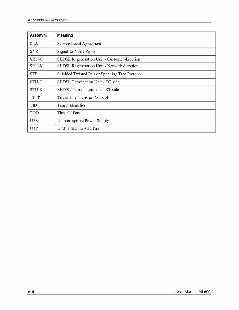
Appendix A - Acronyms
A-4 User Manual ML600
Acronym Meaning
SLA Service Level Agreement
SNR Signal-to-Noise Ratio
SRU-C SHDSL Regeneration Unit - Customer direction SRU-N SHDSL Regeneration Unit - Network direction
STP Shielded Twisted Pair or Spanning Tree Protocol
STU-C SHDSL Termination Unit - CO side
STU-R SHDSL Termination Unit - RT side
TFTP Trivial File Transfer Protocol
TID Target Identifier
TOD Time Of Day
UPS Uninterruptible Power Supply
UTP Unshielded Twisted Pair

Appendix B - Parts List
ML600 User Manual B-1
This appendix summarizes the items which can be ordered from Actelis, including: • SFP Modules
• SW and Documentation
• Cables
• Accessories
, B 16 Appendix B - Parts List

Appendix B - Parts List SFP Modules
B-2 User Manual ML600
SFP Modules
Note: ML638 RoHS6 compliant support multi-rate SFP (100 Mbps / 1000 Mbps)
Table 97: SFP Modules
Item Description Part Number
CLEI Code
1000Base-LX SMF SFP module
1.25Gbps, Single Mode, 1310nm, 10 km, LC connector, Bail de-latch
506R00002 M3C1HH0BAA
1000Base-SX MMF SFP module
1.25Gbps, Multi Mode, 850nm, 500m, LC connector, Bail de-latch
506R00012 M3C1HG0BAA
100Base-FX MMF SFP module
125 Mbps, Multi Mode, 1310 nm, 2km, LC connector, Bail de-latch option
506R00022 COUIABEGAA
100Base-FX SMF SFP module
125 Mbps, Single Mode, 1310 nm, 15km, LC connector, Bail de-latch
506R00032 COUIABDGAA
1000Base-T SFP module Rate 1.25Gbps, 100m, RJ-45 connector 506R00042 COUIABCGAA MIRIC-T3 Ethernet over T3 (Unframed, HDLC) SFP module
44.736 Mbps, 75Ohm, unbalanced, 68m, mini-SMB connector. Shipped with two SMB-to-BNC cables.
506R00052 COUIACMGAA
MIRIC-E3 Ethernet over E3 (Unframed, HDLC) SFP module
34.368 Mbps, 75Ohm, unbalanced, 275m, mini-SMB connector. Shipped with two SMB-to-BNC cables.
506R00062 N/A
Ethernet over T3 SFP module, 1000Base-TX version 2.0
GFP (G.7041) encapsulation, 44.736 Mbps, Gigabit Ethernet port based MSA compliant SFP, 75Ohm, unbalanced, 275m (900ft), DIN 1.0/2.3 connector. Shipped with two 30 cm (11.8 in) DIN 1.0/2.3-to-BNC cable adaptors
506R00072 N/A
Ethernet over T3 SFP module, 100Base-FX - version 2.0
GFP (G.7041) encapsulation, 44.736 Mbps, Fast Ethernet port based MSA compliant SFP, 75Ohm, unbalanced, 275m (900ft), DIN 1.0/2.3 connector. Shipped with two 30 cm (11.8 in) DIN 1.0/2.3-to-BNC cable adaptors
506R00082 N/A
SFP 1310nm Single mode Transceiver GbE IR 40Km
Broadband Long Reach Optical Transceiver, up to 2.125Gbps bi-directional data link, Single Mode, 1310 nm, 40 km
506R51750 N/A
Table 98: CWDM Products
Item Description P/N CLEI Code Add Drop Module 1310nm/1550nm (LADM-1310-1550)
2-wavelength (1310 nm and 1550 nm) CWDM Add and Drop MUX plug-in module, compatible with SP40 chassis
506R51510 N/A

Appendix B - Parts List
ML600 User Manual B-3
BSFP Transceiver, 1550nm, GbE, 80km
Broadband Long Reach Optical Transceiver, up to 2.125Gbps bi-directional data link, Single Mode, 1550 nm, 80 km
506R51714 N/A
CADM Coarse Add Drop Module, 1550nm (CADM-1550)
1550 nm wavelength CWDM Add and Drop MUX plug-in module, compatible with SP40 chassis
506R51514 N/A
CADM Coarse Add Drop Module, 1610nm (CADM-1610)
1610 nm wavelength CWDM Add and Drop MUX plug-in module, compatible with SP40 chassis
506R51511 N/A
CSFP Transceiver 1610nm, GbE, 80km
CWDM Pluggable SFP Transceiver, 1610nm, up to 1.25 Gb/s bi-directional data links, 80km
506R51711 N/A
CSFP Transceiver, 1510nm GbE, 80km
CWDM Pluggable SFP Transceiver, 1510nm, up to 1.25 Gb/s bi-directional data links, 80km
506R51716 N/A
CSFP Transceiver, 1550nm GbE, 80km
CWDM Pluggable SFP Transceiver, 1550nm, up to 1.25 Gb/s bi-directional data links, 80km
506R51712 N/A
CSFP Transceiver, 1570nm GbE, 80km
CWDM Pluggable SFP Transceiver, 1570nm, up to 1.25 Gb/s bi-directional data links, 80km
506R51713 N/A
CSFP Transceiver, 1610nm GbE, 120Km
CWDM Pluggable SFP Transceiver, 1610nm, up to 1.25 Gb/s bi-directional data links, 120km
506R61120 N/A
CWDM Mux/Demux - Band2 Coarse Mux/Demux Four Channel Wavelengths Band 2, 1570-1550-1530-1510nm
506R51612 N/A
Stackable Chassis, 4 slot, 1RU 19 or 23 (SP40)
4-slot chassis for CWDM MUX plug-in modules
502R60510 N/A

Appendix B - Parts List ML600 SW and Documentation
B-4 User Manual ML600
ML600 SW and Documentation
Table 99: SW and Documentation
Item Description Part Number CLEI Code
MetaASSIST EMS Server CD
CD includes: MetaASSIST EMS Server with HSQL database, available for PC and UNIX.
515R00061 N/A
MetaASSIST EMS Client CD
CD includes: MetaASSIST EMS Client application, available for PC and UNIX.
515R00060 N/A
ML600 Quick Installation Guide Hardcopy
ML600 Quick Installation Guide Hardcopy 520R50160E N/A
ML130/1300/2300 R6.1 CD
ML130/1300/2300 CD containing R6.1 Software, and Documentation
522R66018E N/A
ML600 R6.1 CD ML600 CD containing R6.1 Software, and Documentation
522R66017E N/A
ML130/1300/2300 R6.0 CD
ML130/1300/2300 CD containing R6.0 Software, and Documentation
522R61302E N/A
ML600 R6.0 CD ML600 CD containing R6.0 Software, and Documentation
522R66011E N/A
ML-Secure ML130/1300/2300 R5.20 CD
ML130/1300/2300 CD containing R5.2 Secure Software, and Documentation
522R51395E N/A
ML-Secure ML1300/130 R5.0 CD
ML130/1300/2300 CD containing R5.0 Secure Software, and Documentation
522R51350E N/A
ML-Secure ML600 R5.2 CD ML600 CD containing R5.2 Secure Software, and Documentation
522R56185E N/A
ML-Standard ML130/1300/2300 R5.20 CD
ML130/1300/2300 CD containing R5.2 Standard Software, and Documentation
522R51390E N/A
ML-Standard ML1300/130 R5.10 CD
ML130/1300/2300 CD containing R5.1 Standard Software, and Documentation
522R51376E N/A
ML-Standard ML600 R5.10 CD
ML600 CD containing R5.1 Standard Software, and Documentation
522R56175E N/A
ML-Standard ML600 R5.2 CD
ML600 CD containing R5.2 Standard Software, and Documentation
522R56180E N/A

Appendix B - Parts List
ML600 User Manual B-5
Cables
Table 100: DSL Cables
Item Description Part Number CLEI Code
12ft/3.6m straight, solid wires, RJ-45 both ends
DSL connections; Solid wires enable connection to terminal block. Use as External Clock cable for ML 1500/150.
504R20020 N/A
10ft/3m, 4xRJ-45 to open end, solid wires
For connecting ML600 DSL lines to a terminal block
504R20110 N/A
50ft/15m, 4xRJ-45 to open end, solid wires
For connecting ML600 DSL lines to a terminal block
504R20130 N/A
100ft/30m, 4xRJ-45 to open end, solid wires
For connecting ML600 DSL lines to a terminal block
504R20140 N/A
150ft/50m, 4xRJ-45 to open end, solid wires
For connecting ML600 DSL lines to a terminal block
504R20170 N/A
10ft/3m, 8xRJ-45 to open end, solid wires
For connecting ML600 DSL lines to a terminal block
504R20120 N/A
50ft/15m, 8xRJ-45 to open end, solid wires
For connecting ML600 DSL lines to a terminal block
504R20150 N/A
100ft/30m, 8xRJ-45 to open end, solid wires
For connecting ML600 DSL lines to a terminal block
504R20160 N/A
150ft/50m, 8xRJ-45 to open end, solid wires
For connecting ML600 DSL lines to a terminal block
504R20180 N/A
PFU MLP cable (8xRJ45->DB25) 0.3m
External PFU-8 cable DB25 male - 8xRJ45 0.3m/1ft
504R06012 N/A
PFU MLP cable (8xRJ45->DB25) 0.6m
External PFU-8 cable DB25 male - 8xRJ45 0.6m/2ft
504R06015 N/A
PFU MLP cable (8xRJ45->DB25) 3m
External PFU-8 cable DB25 male - 8xRJ45 3m/10ft
504R06017 N/A
1ft/30cm, 4xRJ-45/P to 1xRJ-45/J, stranded wires
For connecting ML600 DSL lines to a Cat-5 reel
504R20090 N/A
Table 101: Service, Alarm, Clock cables
Item Description Part Number CLEI Code
Alarm Cable ML to PFU 0.3m/1ft PFU alarm cable, ML to PFU-8/PFU-8E, Length 0.3m/1ft
504R06065 N/A
Craft i/f cable, DB-9 con. both ends
Craft management cable, DB-9 connectors on both sides, 3m/10ft
504R20010 N/A

Appendix B - Parts List Cables
B-6 User Manual ML600
E1/T1 crossed stranded cable, 3m, RJ-45 both ends
For ML650 E1/T1 service connection, RJ-45 both ends, 3m/10ft
504R20036 N/A
Eth (crossed), stranded STP 12ft/3.6m, RJ-45 both ends
Eth crossed cable, strand. 12ft/3.6m, RJ-45 both ends
504R20025 N/A
Eth straight, strand. 12ft/3.6m, RJ-45 both ends
Shielded Eth straight cable. 12ft/3.6m, RJ-45 both ends. Can be used for DSL connections as well.
504R20030 N/A
MGT Cable ML to PFU 0.3m/1ft PFU AUX monitoring cable, ML to PFU-8/PFU-8E, Length 0.3m/1ft, RJ-45 on both sides
504R06060 N/A
Table 102: Power and Grounding Cables
Item Description Part Number CLEI Code
20ft/6m open ended, 48VDC 18AWG, Gnd 14AWG
Power harness for DC power 504R20043 N/A
AC Power cord, Australian type Australia power cord -3X 1mm 1.8MR LENGTH BLACK
199A10040 N/A
AC Power cord, Itallian type Italy power cord 3X1mm 1.8MR LENGTH BLACK
199A10050 N/A
AC Power cord, Swiss type Swiss power cord 3X1mm 1.8MR 199A10060 N/A AC Power cord, UK type UK power cord 3X 1mm 1.8MR
BLACK 199A10070 N/A

Appendix B - Parts List
ML600 User Manual B-7
Accessories Table 103: Kits
Item Description P/NNumber CLEI Code Accessories Kit Accessories Kit for ML600 510K00060 N/A AC-DC Adapter EU AC-DC Adapter with European inlet
for ML50/ML600 506R00005E N/A
AC-DC Adapter AC-DC Adapter with North American inlet for ML50/ML600
506R00005 N/A
Installation Kit Installation Kit for a ML50/ML600 Link
510K05001 N/A
Sleeve Extension Slide Kit Installation
Sleeve Extension Slide Kit for ML50/ML600
502R05080 N/A
Rack Mount Kit Rack Mount Kit for ML50/ML600 510R21070 COMNH00DRA Wall Mount Kit Wall Mount Kit for ML50/ML600 510R21080 N/A Wall Mount Kit, Flat faced Wall Mount Kit, flat faced, for
ML50/ML600 510R50955 N/A
Table 104: Repeaters Related Items
Item Description P/N CLEI Code EFM Loop Analyzer for ML58 Rev. B
Single portable complete case for field testing and troubleshooting of Actelis EFM based links. Includes ML58N Rev B, PFU-8 and XR239 repeater, copper and test connectors.
501R00012 N/A
EFM Loop Analyzer for ML628 ingle portable complete case for field testing and troubleshooting of Actelis EFM based links. Includes ML628, PFU-8 and XR239 repeater, copper and test connectors
501R00011 N/A
Table 105: Power Supply
Item Description P/N CLEI Code Newmar -48VDC Unity Fuse Panel
Newmar -48VDC Unity Fuse Panel 506R04820 N/A
Newmar -48VDC Unity rectifier
Newmar -48VDC Unity rectifier 506R04815 N/A
Newmar -48VDC Unity rectifier shelf
Newmar -48VDC Unity rectifier shelf
502R04810 N/A
Newmar Battery Module Newmar Battery Module 506R04830 N/A Newmar Battery module shelf Newmar Battery module shelf 502R04825 N/A Newmar Rear support bracket Newmar Rear support bracket 508R04835 N/A


Accessories Appendix C - Technical Specifications
ML600 User Manual C-1
This appendix contains the following ML600 specifications:
• General Specifications (on page 2)
• Supported SNMP MIBs (on page 5)
• Customer Logs (on page 6)
• Available Spectral Modes (on page 8)
, C 17 Appendix C - Technical Specifications

Appendix C - Technical Specifications ML600 Specifications
C-2 User Manual ML600
ML600 Specifications Table 106: ML600 Specifications
Interfaces Ethernet Service • 10/100Base-TX IEEE 802.3 4 ports Connector: RJ45, Auto-MDIX • 100/1000Base-Fx (option) 1 port Connector: SFP based, MSA compliant T1/E1 (ML650 only) •
Interface 4 ports RJ45 (RJ-48c) T1: Balanced 100Ω; E1 Balanced 120Ω
•
Framing T1: Unframed, SF and ESF, both clear channel and fractional E1: Unframed, E1 (PCM31) and E1-CRC (PCM31 CRC), both clear channel and fractional
•
Line Code T1: B8ZS or AMI E1: HDB3 or AMI.
•
Sensitivity Long haul: T1 -36 dB (@772kHz); E1 -43 dB (@1,024kHz). Short haul: T1 -10 dB (@772kHz); E1 -10 dB (@1,024kHz).
•
LBO (Line Build Out) Configurable (for T1): 0 ÷ 133, 134 ÷ 266, 267 ÷ 399, 400 ÷ 533 and 534 ÷ 655 feet.
•
TX PBO (Power Back Off) Configurable (for Long haul): 0 dB, -7.5 dB, -15 dB and -22.5dB
•
Standard Compliance T1: ANSI T1.403, ITU-T G.704, G.706, G.734 and G.824 E1: ITU-T G.703, G.706, G.732 and G.823
•
Latency Configurable (few milliseconds)
•
Clock Synchronization Resilient, highly accurate clock transfer, better than stratum 3. Hold over support
High Speed Link (Bonded copper Pairs) • Protocol IEEE 802.3ah 2Base-TL; ITU-T G.998.3 (G.Bond/Ethernet) • Line code ITU-T G.991.2 rev. 2 • Bandwidth Up to ~100 Mbps (symmetrical) for RoHS compliant products (PN
501R0xxxx) Up to 1-~45 Mbps (symmetrical) for non RoHS compliant products (PN 501R0xxxx)
• Number of Copper Pairs 1- 8 Connector: RJ45 (per modem/pair) • End-to-end Delay 2-4ms (typical) • Sealing Current 48VDC/1.5mA nominal • BER 10E-10 (typical);10E-6 (guaranteed) • Spectral Controls Selectable from comprehensive list of ITU-T, ETSI, ANSI country-specific or
customized Spectral Modes • Copper Pairs Test Tools TDR – Time Domain Reflectomtry
Audible Tone Injection Loopback

ML600 Specifications Appendix C - Technical Specifications
ML600 User Manual C-3
Management (Out-of-Band) • 10/100Base-TX 1 port (dedicated) - port may be used as service port as well Connector: RJ45, Auto-MDIX • Craft EIA RS-232 (DCE) port Connector: DB9
Ethernet Bridge Features • Speed/duplex mode Auto-negotiation or manually 10/100/1000(option) HALF/FULL
• Flow control IEEE 802.3x (pause frames for FULL/back pressure for HALF DUPLEX modes)
• Link Aggregation IEEE 802.3ad
• EFM OAM IEEE 802.3ah clause 57, including Dying GASP
• Bridging IEEE 802.1d/p/q
• Min tagged frame size 64 bytes
• Maximum Frame Size All models except for ML640/ML650 - 1632 bytes ML640/ML650 - 1630 bytes
• Forwarding Database size 8K
• Double Tagging Q-in-Q , Ethernet Type 0x8100 (configurable)
• VLANs 255 user defined Traffic VLANs + 1 user defined MGMT VLAN, for VIDs in range from 1 to 4094
• Maximum Burst Size ~250 frames for 64-byte length frames; ~60 frames for 1532-byte length frames;
• RSTP, STP IEEE 802.1d compliant
• Provider Bridge IEEE 802.1ad compliant
• CFM / MEF OAM IEEE 802.1ag compliant
• LLDP IEEE 802.1ab compliant
Quality of Service Features • Class of Service (Queues) 4 (ML640/ML650 – 8)
• Scheduler WFQ or SP (ML640/ML650 –WFQ, SP or Hybrid) • Classification By L2 COS bits (802.1p) , by L3 ToS/DiffServ or by Port • Marking Into L2 COS bits (802.1p) of outer VLAN tag
MEF Services (ML640/ML650 models) • MEF Compliancy MEF9 & MEF14 certified, MEF10 compliant
MEF8 & MEF18 certified (ML650) • EVCs 8 • Classification Rules 32 ingress rules (Port/VLAN/L2/L3/L4 Flexible) • BW control 32 profiles, each one with CIR, CBS, EIR, EBS configurable • Ingress policing Two rates/3 color ingress traffic metering (green (CIR+CBS), Yellow
(EIR+EBS), red (exceeds BW profile) • Scheduler SP, WFQ or Hybrid, Weights 1:15 configurable • Egress limiting and shaping Shaping per service Flow and Egress limiting per HSL port
Management Management Applications • EMS MetaASSIST EMS

Appendix C - Technical Specifications ML600 Specifications
C-4 User Manual ML600
• Craft GUI MetaASSIST View Protocols • SNMP SNMP v1 and v2c • Command Line Interface TL1 • Remote Access Telnet • Secure Access (option) SSH v2 • Time Synchronization SNTP v3 • Web Access HTTP • File Transfer FTP, TFTP
Front Panel Indicators (LEDs) • Power• Status• Alarm • MLP per modem/pair • ACT (Activity) and LNK (Link) per Ethernet/HSL port • ERR (Error) and LNK (Link) per E1/T1 port (ML650 only)
Alarm Contacts • Terminal Block : 2 Input, 1 Output Max voltage/current 72VDC/120mA max
Physical • Dimensions Height: 1.6” / 40mm (1U) Depth: 11.0” / 280mm Width: 8.4” / 213mm • Weight: 3.75 lbs / 1.7 Kg • Mounting Rack: 2 units in 19”, 23” or ETSI racks Desktop and Wall Mount
Power • DC: -48/-60 VDC nominal
13.5 to 22 Watt (model dependent) ML622 8W, ML624/644 9W, ML628/ML648 15W, ML654 20W, ML658 22W
• AC: External adapter 90 to 264 VAC, 47-63 Hz 17 to 28 Watt (per model)
Environmental • Operating Temp. -40° to +65°C • Storage Temp. -40° to +70°C • Relative humidity Up to 95%, non-cond.
Certification and Compliancy • Safety UL 60950-1, EN 60950-1, CSA C22.2 60950-1, IEC 60950-1 • EMC FCC Part 15 Class B, ICES-003 Class B
ETSI EN 300 386 Class B ETSI ETS 300 132-2
• CE certified EMC and Safety • Environmental GR-63-CORE
ETSI ETS 300 019

Supported SNMP MIBs Appendix C - Technical Specifications
ML600 User Manual C-5
Supported SNMP MIBs The following SNMP MIBs are supported:
• System group [RFC-1213]
• Interface ifTable [RFC-1213/RFC-2863]
• IfInvertedStack MIB [RFC-2864]
• Bridge MIB [RFC-1493] and [RFC-4188]
• Extended Bridge MIB [RFC-4363]
• RSTP MIB [RFC-4318]
• Entity MIB [version 2, RFC-2737] and [RFC-4133]
• Entity State MIB [RFC-4268]
• EFM-CU-MIB [RFC 5066]
• DOT3-OAM-MIB [RFC 4878]
• RMON MIB [RFC-2021]
• SHDSL MIB [RFC-4319]
• IEEE8021-CFM-MIB(IEEE draft 8)
• Radius Client Authentication MIB [RRFC2618 and RFC4668]
• DS1-MIB [RFC 3895] - ML650 Only

Appendix C - Technical Specifications Customer Logs
C-6 User Manual ML600
Customer Logs • Customer Logs - 2x1Mbyte:
• COMMAND (Collect all TL1 commands) - 1 Mbyte
• AUDIT (Collect all attempts to connect to ML device: HTTP, TL1/telnet, TL1/SSH, SNMP, SNTP, etc.) - 1Mbyte.
• Support Logs (for internal use) - 3x1Mbyte:
• INSTALL
• INFO
• BLACKBOX

Spectral Compatibility Standards Appendix C - Technical Specifications
ML600 User Manual C-7
Spectral Compatibility Standards
World Wide Spectral Compatibility Actelis systems comply with established worldwide spectral mode standards, such as:
• ANSI T1.417;
• ITU-T G.991.2 Annex A, Annex B, Annex F, Annex G;
• ETSI TS 101 524 Annex E.
In addition, Actelis systems comply with country specific spectral mode standards. See Available Spectral Modes (on page 8).
A specific spectral mode can be set, limiting spectral characteristics of modems to comply with a particular standard.

Appendix C - Technical Specifications Available Spectral Modes
C-8 User Manual ML600
Available Spectral Modes The following table lists the available Spectral Modes.
Table 107: Supported Spectral Modes
Spectral Mode
Description
NA1 Compliant with ITU-T G.991.2 Annex F. Enables modem rates up to 5.7 Mbps (with an option for up to 8.5 Mbps)
NA2 Compliant with ITU-T G.991.2 Annex F and ANSI T1.417. Enables modem rates up to 5.7 Mbps (with an option for up to 8.5 Mbps). Rates are subject to limiting (per reach).
NA3 Compliant with ANSI T1.417. Allows PAM16, PAM32, PAM64 and PAM128 constellation as well as higher baud rate. Enables modem rates up to 15.2 Mbps. Rates are subject to limiting (per reach).
EU1 Compliant with ITU-T G.991.2 Annex G, allows PAM32 constellation and Extended PSD mask. Enables modem rates up to 5.7 Mbps.
EU2 Compliant with ITU-T G.991.2 Annex B and ETSI TS 101 524. Enables modem rates up to 2.3 Mbps.
EU3 Compliant with ITU-T G.991.2 Annex B, but additionally allows PAM32 constellation. Enables modem rates up to 3.1 Mbps (with an option for up to 4.6 Mbps).
EU4 Compliant with ETSI TS 101 524 Annex E and ITU-T G.991.2 Annex G. Enables modem rates up to 5.7 Mbps (with an option for up to 8.5 Mbps)
EU5 Compliant with UK ANFP (Access Network Frequency Plan) for British Telecom, according to NICC ND1602:2005/08. Enables modem rates up to 3.1 Mbps (with an option for up to 4.6 Mbps). Rates are subject to limiting (per reach). Power Back-Off as specified in ETSI 101 524, Annex E.
EU6 Compliant with Belgian Institute for Postal services and Telecommunications (BIPT) Spectral Management regulation for the Belgian access network as specified in BIPT BRUO 2005 "Belgacom Row Copper and Shared Pair Products - Technical Specifications", Annex C. Enables modem rates up to 5.7 Mbps , limited per reach (with an option for up to 8.5 Mbps). Power Back-Off as specified in ETSI 101 524, Annex E.
EU7 Compliant with SOO, Netherlands SDSL Spectral Management regulation and xDSL deployment rules for the Dutch access network. Enables modem rates up to 5.7 Mbps, limited per reach (with an option for up to 8.5 Mbps). Power Back-Off as specified in ETSI 101 524, Annex E.
EU8 Compliant with German, DT, Spectral management regulations. Enables modem rates up to 5.7 Mbps, limited per reach (option for up to 8.5). Power Back-Off as specified in ETSI 101 524, Annex E.
EU9 Compliant with Denmark, TDC, Spectral Management regulation. Enables modem rates up to 5.7 Mbps (with an option for up to 8.5 Mbps), limited per reach. Power Back-Off as specified in ETSI 101 524, Annex E.
EU10 Compliant with UK ANFP (Access Network Frequency Plan) for British Telecom, according to NICC ND1602:2007/03. Enables modem rates up to 5.7 Mbps (with an option for up to 8.5 Mbps), limited per reach. Power Back-Off as specified in ETSI 101 524, Annex E.
EU11 Compliant with Spain - "High Quality" pairs. Enables modem rates up to 5,696 Kbps, limited per reach (with an option for up to 8.5). Power Back-Off as specified in ETSI 101 524, Annex E.

Available Spectral Modes Appendix C - Technical Specifications
ML600 User Manual C-9
EU12 Compliant with Spain - "Low Quality" pairs. Enables modem rates up to 4,224 Kbps, limited per reach (with an option for up to 6.3 Mbps). Power Back-Off as specified in ETSI 101 524, Annex E.
EU13 NOT IN USE
EU14 Compliant with Switzerland Spectral Management regulation. Enables modem rates up to 5.7 Mbps, limited per reach (with an option for up to 8.5 Mbps). Power Back-Off as specified in ETSI 101 524, Annex E.
EU15 Compliant with Telekom Austria Spectral Management regulation. Enables modem rates up to 5.7 Mbps, limited per reach (with an option for up to 8.5 Mbps). Power Back-Off as specified in ETSI 101 524,Annex E.
EU16 Compliant with Sweden Spectral Management regulation. Enables modem rates up to 5.7 Mbps, limited per reach (with an option for up to 8.5 Mbps). Power Back-Off as specified in ETSI 101 524, Annex E.
EU17 Compliant with Ireland Spectral Management regulations. Enables modem rates up to 5.7 Mbps (with an option for up to 8.5 Mbps). Power Back-Off as specified in ETSI 101 524, Annex E.
EU18 Compliant with Finland's Spectral Management regulations. Enables modem rates up to 5.7 Mbps (with an option for up to 8.5 Mbps). Power Back-Off as specified in ETSI 101 524, Annex E.
EU19 Compliant with ARCEP France regulations. Enables modem rates up to 5.7 Mbps (with an option for up to 8.5 Mbps). Power Back-Off as specified in ETSI 101 524, Annex E.
AP1 Compliant with Japan Telecommunication Technology Committee Spectrum Management for Metallic Transmission Systems, according to TTC JJ-100.01. Enables modem rates up to 4.6 Mbps. Rates are subject to limiting (per reach). Power Back-Off as specified in ITU-T G.991.2
AP2 Compliant with the PSD limits of Japan Telecommunication Technology Committee Spectrum Management for Metallic Transmission Systems, TTC JJ-100.01 standard. Enables modem rates up to 6.9 Mbps. Power Back-Off as specified in ITU-T G.991.2.
NOLMT No Limit, Compliant with PAM16, PAM32, PAM64 and PAM128 constellation and Extended PSD mask up to 2.5 Mbaud. Enables modem rates up to 15.2 Mbps.
For Repeater installations: 1. Minimal rate with repeaters is 960 Kbps (Rate 15) using TC-PAM 16 and 1,280 Kbps
(Rate 20) using TC-PAM 3 2. Rate limit in all spectral modes is set by the EWL of the longest segment. 3. NA2 is not supported with repeaters. 4. PBO in all spectral modes is set to 0dB regardless of requested spectral mode (unless
min. PBO is configured).


Appendix D - Factory Setup Content
ML600 User Manual D-1
This appendix describes the factory setup for the ML600 models, where the factory setup for each model is described in the appropriate sub-section.
, D 18 Appendix D - Factory Setup Content

Appendix D - Factory Setup Content ML6xx Factory Setup
D-2 User Manual ML600
ML6xx Factory Setup
Table 108: ML6xx Units Factory Setup Content
Management TL1 access Default User (Admin/Admin, Write/Write, Read/Read) accounts, Local DB of user
accounts is in use (not Radius). Access From Peer (via HSL) Enabled - relevant to non-IP (Fast OAM) access. Management control via EOC
from STU-R to STU-C modem is permanently disabled. Management control via EOC from STU-C to STU-R modem is permanently enabled.
Craft Enabled, with 9,600-baud rate IP access IP address = 0.0.0.0, Subnet mask = 255.255.0.0, Gateway = 0.0.0.0. Radius Client Disabled , no Radius Server is Configured LLDP (Link Layer Discovery Protocol)
Disabled system-wide. When enabled, applicable on ETH-x/COLAN ports only.
System identification Unique TL1 TID and SNMP System ID, initialized by serial number of ML600 system
SNMP access Default read access string is set to “public”. Default write access string is set to “private”. SNMP Traps are on, but Destination Addresses are empty. Trap Source OID is set to MIB-II.
Security All security features are OFF (ACL, Radius Client, SSH, PWD complexity, failed login control, etc.). Local User Accounts in use (Radius Server is not used).
Log files All are enabled, Command log Level =2 PM counters Enabled, PM day start time is 0 (00-00); Thresholds on PM counters are disabled. Time of Day No time is set. TOD = Local, Time Zone=0, DST is Off, SNTP Client is Off. Alarm led Fully enabled
2Base-TL bonding HSL Enabled, without Calibration target setting ML688: HSL-1 –O (Office) mode; HSL-2 -R (Customer) mode;
Other ML600 models: HSL-1 –R (Customer) mode HSL LOWBW alarm threshold Disabled MLP All are entered and assigned to HSL-1, silently waiting for CO to start
synchronization. Sealing current Disabled
Ethernet Port Physical ETH-x ETH-{1-4} - enabled. Mode=Auto, Pinout =MDI, Flow control=OFF. ETH-{5-6}
(option on some models) is enabled (Mode=Auto, Flow control=OFF) only if SFP is plugged in.
COLAN Disabled. When enabled, Mode=Auto, Pinout =MDIX, Flow control=OFF HSL-1 Enabled LAG-x Not entered Ethernet Ports EFM OAM EFM OAM is OFF. When enabled (per port) is set to ACTIVE mode

Appendix D - Factory Setup Content
ML600 User Manual D-3
Ethernet Bridge
VLAN awareness Enabled (by 802.1Q mode) VLAN Tag type 0x8100 PPPoE tunnel forwarding Disabled. PPPoE feature is available on ML624, ML628 and RoSH compliant
ML622. FRWDB learning Enabled FRWDB aging Enabled, 300 sec
VLANs VLANs Simultaneous support up to 256 VLANs, in range {1-4095}.
Note: VID=4093 is permanently reserved (for PPPoE feature) on all ML600 models. VID=4092 is permanently reserved on ML640/650 models.
MGMT VLAN VID= 100 is set for CPU, COLAN (untagged), and all HSL (tagged), even not entered
Service VLAN For ML62x and ML63x:
VID=101: ETH-1/S + HSL-1/T VID=102: ETH-2/S + HSL-1/T VID=103: ETH-3/S + HSL-1/T VID=104: ETH-4/S + HSL-1/T VID=105: ETH-5/S + HSL-1/T Where S - Stacked, T- Tagged
For ML688: VID=101: ETH-1/U +HSL-{1-2}/T VID=102: ETH-2/U+ HSL-{1-2}/T VID=103: ETH-3/U+ HSL-{1-2}/T VID=104: ETH-4/U+ HSL-{1-2}/T VID=105: ETH-5/U+ HSL-{1-2}/T Where U - Untagged, T- Tagged
Ethernet Bridge CoS Scheduler type ML600: WFQ (Weighted Fair Queue), 4 queues with weights (non-configurable):
Highest (HH) -8, High (MH)-4, Medium (L)-2, Low (LLL)-1 ML640/650: 2 SP (Strict Priority) – 6 WFQ (Weighted Fair Queue), 6 queues with weights (configurable): H-8, MH-4, ML-2, L-2, LL-1, LLL-1
WFQ CLASS weights un-configurable Highest (HH) -8, High (MH)-4, Medium (L)-2, Low (LLL)-1
L2Prio-to-CLASS classification COS bits {0,1} – Low (LLL), COS bits {2,3} – Medium (L), COS bits {4,5} – High (MH), COS bits {6,7} – Highest (HH).
L3Prio-to-CLASS classification TOS bits {0-15} – Low, TOS bits {16-31} – Medium, TOS bits {32-47} – High, COS bits {48-63} - Highest.
L2Prio Translation (HSL ingress applicable) transparent (L2Prio is unchanged)
CLASS-to-L2Prio mapping (HSL egress applicable) HHH - 7, HH - 6, H - 5, MH - 4, ML - 3, L - 2, LL - 1, LLL - 0
Ethernet Port QoS
Classification on ETH-x – “by L2PRIO”, on COLAN – HH (Enforced) Ingress rate limiting OFF on all allowed ports (allowed on ETH-x, HSL-x, COLAN) Egress rate limiting OFF on all allowed ports (allowed only on HSL-x) Ingress Limit burst Not allowed (per bridge configured)

Appendix D - Factory Setup Content ML6xx Factory Setup
D-4 User Manual ML600
Ethernet Services (BW limiting) EVCs not entered
STP STP system-wide Disabled. When enabled, protocol type is set to RSTP by default. Port setting ON in all ETH ports (ETH-x, COLAN and HSL-x). STP path costs defaults set for RSTP
20,000,000 on COLAN/MGMT port 2,000,000 on HSL-x port
STP path for configured ETH If AUTO ETH-1-4: 2,000,000, ETH-5/6 - 200,000 If 10Mbps 2,000,000 If 100Mbps 200,000 If 1000Mbps 20,000
L2CP
Cisco Reserved MACs: 01-00-0C-00-00-00 (Cisco ISL),
01-00-0C-CC-CC-CC (Cisco CDP), 01-00-0C-CC-CC-CD (Cisco PVST+)
L2CP disabled -bypass L2CP control
MAC 01-80-C2-00-00-00 (STP) PEER on all Ports MAC 01-80-C2-00-00-01 (Pause Frames) PEER on all Ports MAC 01-80-C2-00-00-02, subtype=2 (OAM) PEER on all Ports MAC 01-80-C2-00-00-02, subtype=3 –10 (UNKNOWN)
DISCARD on all Ports
MAC 01-80-C2-00-00-02, subtype=0 or >11 permanently dropped as illegal MAC 01-80-C2-00-00-0E (LLDP) PEER on ETH-x and COLAN Ports, DISCARD on HSL-x Ports MAC 01-80-C2-00-00-{03-0F}, 10, {20-21} DISCARD on all Ports

Appendix D - Factory Setup Content
ML600 User Manual D-5
ML62x, ML63x and ML68x Specific Setup
ML62x, ML63x and ML68x Dip Switch Configuration
Table 109: ML62x, ML63x and ML68x Dip Switch Configuration
DS#1 DS#2 DS#3 DS#4 Description On Off Off Off ML600 performs as CPE device (not re-configurable), in
802.1D bridge mode (not re-configurable). STP per system and port is enabled (can be disabled by per port configuration). Alarm led performs partially (reports PROGFLT alarm only). NOSETUP alarm is not raised. ETH-{1-5} are as in factory setup: all enabled with Mode=Auto, Pinout=MDI, Flow control=OFF.
On On Off Off ML600 performs as CO device (not re-configurable).HSL is Auto-Calibrated, i.e. starts calibration on each restart with Best Effort, EU1 Spectral Mode and 3dB SNR margins as target (Calibration BW Target, SNR Margin and Spectral Mode can be reconfigured). 802.1D bridge mode (not re-configurable) is available. STP per system and port is enabled (can be disabled by per port configuration). Alarm led performs partially (reports PROGFLT alarm only). NOSETUP alarm is not raised. ETH-{1-5} are as in factory setup: all enabled with Mode=Auto, Pinout=MDI, Flow control=OFF.
Off Off On Off ML600 performs as CPE device (not re-configurable), in 802.1D bridge mode (is configurable). If Q-bridge mode is configured Factory MGMT VID is set on HSL only = 4020 (Tagged). Alarm led performs partially (reports PROGFLT alarm only). NOSETUP alarm is raised. ETH-{1-5} are configured as: • ETH-1: Mode=Auto, Pinout=MDIX, Flow control=OFF • ETH-2: Mode=10M HD, Pinout=MDIX, Flow control=OFF • ETH-3: Mode=10M FD, Pinout=MDIX, Flow control=OFF • ETH-4: Mode=100M FD, Pinout=MDIX, Flow control=OFF • ETH-5: Mode=Auto, Pinout=MDI, Flow control=OFF
All other configurations are invalid, see ML600 Quick Installation Guide to troubleshoot Dip Switch setup.

Appendix D - Factory Setup Content ML640 Specific Factory Setup
D-6 User Manual ML600
ML640 Specific Factory Setup
ML640 Rules and Services
Table 110: ML640 Services and Rules Factory Setup
Ethernet Services (BW limiting and CLASS of Service)
EVCs not entered
EVC Services SERV-1: EVC AID= “”, DESCR = “INTERNAL HIGH”, BWPROFILEID = 0, QUEUE=HHH SERV-2: EVC AID= “”, DESCR = “INTERNAL LOW”, BWPROFILEID = 0, QUEUE=LLL SERV-3: EVC AID= “”, DESCR = “DEFAULT MGMT”, BWPROFILEID = 0, QUEUE=HHH SERV-4: EVC AID= “”, DESCR = “HIGHEST SERVICE UNLIMITED QUEUE”, BWPROFILEID
= 0, QUEUE=H //scheduled as WFQ with weight=8 SERV-5: EVC AID= “”, DESCR = “HIGH SERVICE UNLIMITED QUEUE”, BWPROFILEID = 0,
QUEUE=MH //scheduled as WFQ with weight=4 SERV-6: EVC AID= “”, DESCR = “MEDIUM SERVICE UNLIMITED QUEUE”, BWPROFILEID =
0, QUEUE=L//scheduled as WFQ with weight=2 SERV-7: EVC AID= “”, DESCR = “LOW SERVICE UNLIMITED QUEUE”, BWPROFILEID = 0,
QUEUE=LLL//scheduled as WFQ with weight=1
Identification Rules
RULE-1: not editable Default Template, All Values, except MACDST, =ANY, MACDST = 01-80-C2-00-00-00, MASKMACDST=FF-FF-FF-FF-FF-F0, PASSTOMETER=Y, SERV-1, MARKING=NONE, DESCR = L2CP MAC=0x0180C200000*
RULE-2: not editable Default Template, All Values, except MACDST, =ANY, MACDST = 01-80-C2-00-00-10, PASSTOMETER=Y, SERV-1, ORDERNUM=-1, MARKING=NONE, DESCR= " L2CP MAC=0x0180C2000010".
RULE-3: not editable Default Template, All Values, except MACDST, =ANY, MACDST = 01-80-C2-00-20,MASKMACDST=FF-FF-FF-FF-FF-FE, PASSTOMETER=Y, SERV-1, MARKING=NONE, DESCR= "L2CP MAC=0x0180C20020/1".
RULE-4: not editable Default Template, All Values, except MACDST, =ANY, MACDST =01-00-0c-00-00-00, MASKMACDST=FF-FF-FF-FF-FF-FF, PASSTOMETER=Y, SERV-1, MARKING=NONE, DESCR="ISL MAC=0x01000C000000”.
RULE-5: not editable Default Template, All Values, except MACDST, =ANY, MACDST =01-00-0c-cc-cc-cc/D, MASKMACDST=FF-FF-FF-FF-FF-FE, PASSTOMETER=Y, SERV-1, MARKING=NONE, DESCR= "CDP/PVST+ MAC=0x01000 CC-CC-CC-C/Dl”.
RULE-6: not editable Default Template, All Values, except MACDST, =ANY, MACDST = 01-80-C2-00-00-30, MASKMACDST=FF-FF-FF-FF-FF-F0, PASSTOMETER=Y, SERV-1, MARKING=NONE, DESCR= "CFM MAC=0x0180C200003*".
RULE-7: Default Template, All Values, except VID, =ANY, EXTTAGVID = 100 (MGMTVID), PASSTOMETER=Y,SERV-3, MARKING=NONE, DESCR= "MGMT VLAN".

Appendix D - Factory Setup Content
ML600 User Manual D-7
RULE-8: Default Template, All Values except EXTTAGTYPE and EXTTAGCOS, =ANY, EXTTAGTYPE =8100,EXTTAGCOS = 0, EXTTAGCOSMASK = 110, PASSTOMETER=Y, SERV-7, MARKING=CLASS-TO-COS,DESCR= "L2PRIO COS ={0-1}".
RULE-9: Default Template, All Values except EXTTAGTYPE and EXTTAGCOS, =ANY, EXTTAGTYPE =8100,EXTTAGCOS = 2, EXTTAGCOSMASK = 110, PASSTOMETER=Y, SERV-6, MARKING= CLASS-TO-COS,DESCR= " L2PRIO COS={2-3}".
RULE-10: Default Template, All Values except EXTTAGTYPE and EXTTAGCOS, =ANY, EXTTAGTYPE =8100,EXTTAGCOS = 4, EXTTAGCOSMASK = 110, PASSTOMETER=Y, SERV-5, MARKING= CLASS-TO-COS,DESCR= " L2PRIO COS={4-5}".
RULE-11: Default Template, All Values except EXTTAGTYPE and EXTTAGCOS, =ANY, EXTTAGTYPE =8100,EXTTAGCOS = 6, EXTTAGCOSMASK = 110, PASSTOMETER=Y, SERV-4, MARKING= CLASS-TO-COS,DESCR= " L2PRIO COS={6-7}".
RULE-32: not editable Default Template, All Values =ANY, PASSTOMETER=Y, SERV-2, MARKING=NONE, DESCR= " ALL THE REST traffic tunnel".
BW Profiles not entered, except to NULL profile – UNLIMITED

Appendix D - Factory Setup Content ML640 Specific Factory Setup
D-8 User Manual ML600
ML640 Dip Switch Configuration
Table 111: ML640 Dip Switch Configuration
DS#1
DS#2
DS#3
DS#4
Description
On Off Off Off ML640 performs as CPE device (not re-configurable), in 802.1Q bridge mode (not re-configurable). STP per system and port is enabled (can be disabled by per port configuration). Alarm led performs partially (reports PROGFLT alarm only). NOSETUP alarm is not raised. ETH-{1-5} are as in factory setup: all enabled with Mode=Auto, Pinout=MDI, Flow control=OFF.
On On Off Off ML640 performs as CO device (not re-configurable). HSL is Auto-Calibrated, i.e. starts calibration on each restart with Best Effort, EU1 Spectral Mode and 3dB SNR margins as target (Calibration BW Target, SNR Margin and Spectral Mode can be reconfigured). 802.1Q bridge mode (not re-configurable) is available. STP per system and port is enabled (can be disabled by per port configuration). Alarm led performs partially (reports PROGFLT alarm only). NOSETUP alarm is not raised. ETH-{1-5} are as in factory setup: all enabled with Mode=Auto, Pinout=MDI, Flow control=OFF.
Off Off On Off ML640 performs as CPE device (not re-configurable), in 802.1Q bridge mode (not configurable). If Q-bridge mode is configured Factory MGMT VID is set on HSL only = 4020 (Tagged). Alarm led performs partially (reports PROGFLT alarm only). NOSETUP alarm is raised. ETH-{1-5} are configured as: • ETH-1: Mode=Auto, Pinout=MDIX, Flow control=OFF • ETH-2: Mode=10M HD, Pinout=MDIX, Flow control=OFF • ETH-3: Mode=10M FD, Pinout=MDIX, Flow control=OFF • ETH-4: Mode=100M FD, Pinout=MDIX, Flow control=OFF • ETH-5: Mode=Auto, Pinout=MDI, Flow control=OFF
All other configurations are invalid, see ML640 Quick Installation Guide to troubleshoot Dip Switch setup.

Appendix D - Factory Setup Content
ML600 User Manual D-9
ML650 Specific Factory Setup
ML650 Rules and Services
Table 112: ML650 Services and Rules Factory Setup
Ethernet Services EVCs not entered EVC Services SERV-1: EVC AID= "", DESCR = "INTERNAL HIGH", BWPROFILEID = 0, QUEUE=HHH SERV-2: EVC AID= "", DESCR = "INTERNAL LOW", BWPROFILEID = 0, QUEUE=LLL SERV-3: EVC AID= "", DESCR = "DEFAULT MGMT", BWPROFILEID = 0, QUEUE=HHH SERV-4: EVC AID= "", DESCR = "HIGHEST SERVICE UNLIMITED QUEUE", BWPROFILEID
= 0, QUEUE=H //scheduled as WFQ with weight=8 SERV-5: EVC AID= "", DESCR = "HIGH SERVICE UNLIMITED QUEUE", BWPROFILEID = 0,
QUEUE=MH //scheduled as WFQ with weight=4 SERV-6: EVC AID= "", DESCR = "MEDIUM SERVICE UNLIMITED QUEUE", BWPROFILEID
= 0, QUEUE=L//scheduled as WFQ with weight=2 SERV-7: EVC AID= "", DESCR = "LOW SERVICE UNLIMITED QUEUE", BWPROFILEID = 0,
QUEUE=LLL//scheduled as WFQ with weight=1 SERV-8 EVC AID= “”, DESCR = “CES over ETH”, BWPROFILEID = 0, QUEUE=HH
Identification Rules
RULE-1: editable L2TEMPLATE = CESOETH, ECID = 1, PASSTOMETER=Y, SERV-8, MARKING=NONE, DESCR = ”DSx1-1-1 CES”.
RULE-2: editable L2TEMPLATE = CESOETH, ECID = 2, PASSTOMETER=Y, SERV-8, MARKING=NONE, DESCR = ”DSx1-1-2 CESl”.
RULE-3: editable L2TEMPLATE = CESOETH, ECID = 3, PASSTOMETER=Y, SERV-8, MARKING=NONE, DESCR = ”DSx1-1-3 CESl”.
RULE-4: editable L2TEMPLATE = CESOETH, ECID = 4, PASSTOMETER=Y, SERV-8, MARKING=NONE, DESCR = ”DSx1-1-4l”.
RULE-5: not editable Default Template, All Values, except MACDST, =ANY, MACDST = 01-80-C2-00-00-00, MASKMACDST=FF-FF-FF-FF-FF-F0, PASSTOMETER=Y, SERV-1, MARKING=NONE, DESCR = "L2CP MAC=0x018-0C-20-00-00*l"
RULE-6: not editable Default Template, All Values, except MACDST, =ANY, MACDST = 01-80-C2-00-00-10, PASSTOMETER=Y, SERV-1, ORDERNUM=-1, MARKING=NONE, DESCR= "L2CP MAC=0x0180C2000010l".
RULE-7: not editable Default Template, All Values, except MACDST, =ANY, MACDST = 01-80-C2-00-00-20/1, MASKMACDST=FF-FF-FF-FF-FF-FE, PASSTOMETER=Y, SERV-1, MARKING=NONE, DESCR= "L2CP MAC=0x0180C20020/1".
RULE-8: not editable Default Template, All Values, except MACDST, =ANY, MACDST =01-00-0c-00-00-00, MASKMACDST=FF-FF-FF-FF-FF-FF, PASSTOMETER=Y, SERV-1, MARKING=NONE, DESCR= "ISL MAC=0x01000C-00-00-00".

Appendix D - Factory Setup Content ML650 Specific Factory Setup
D-10 User Manual ML600
RULE-9: not editable Default Template, All Values, except MACDST, =ANY, MACDST =01-00-0c-cc-cc-cc/D, MASKMACDST=FF-FF-FF-FF-FF-FE, PASSTOMETER=Y, SERV-1, MARKING=NONE, DESCR= "CDP/PVST+ MAC=0x01000CCCCCCC/D".
RULE-10: not editable Default Template, All Values, except MACDST, =ANY, MACDST = 01-80-C2-00-00-30, MASKMACDST=FF-FF-FF-FF-FF-F0, PASSTOMETER=Y, SERV-1, MARKING=NONE, DESCR= "CFM MAC=0x0180C200003".
RULE-11: editable Default Template, All Values, except VID, =ANY, EXTTAGVID = 100 (MGMTVID), PASSTOMETER=Y, SERV-3, MARKING=NONE, DESCR= "MGMT VLAN".
RULE-12: editable Default Template, All Values except EXTTAGTYPE and EXTTAGCOS, =ANY, EXTTAGTYPE =8100, EXTTAGCOS = 0, EXTTAGCOSMASK = 110, PASSTOMETER=Y, SERV-7, MARKING=CLASS-TO-COS, DESCR= " L2PRIO COS {0-1}".
RULE-13: editable Default Template, All Values except EXTTAGTYPE and EXTTAGCOS, =ANY, EXTTAGTYPE =8100, EXTTAGCOS = 2, EXTTAGCOSMASK = 110, PASSTOMETER=Y, SERV-6, MARKING= CLASS-TO-COS,DESCR= "L2PRIO COS={2-3}".
RULE-14: editable Default Template, All Values except EXTTAGTYPE and EXTTAGCOS, =ANY, EXTTAGTYPE =8100, EXTTAGCOS = 4, EXTTAGCOSMASK = 110, PASSTOMETER=Y, SERV-5, MARKING= CLASS-TO-COS, DESCR= " L2PRIO COS={4-5}".
RULE-15: editable Default Template, All Values except EXTTAGTYPE and EXTTAGCOS, =ANY, EXTTAGTYPE =8100, EXTTAGCOS = 6, EXTTAGCOSMASK = 110, PASSTOMETER=Y, SERV-4, MARKING= CLASS-TO-COS, DESCR= " L2PRIO COS={6-7}".
RULE-32: not editable Default Template, All Values =ANY, PASSTOMETER=Y, SERV-2, MARKING=NONE, DESCR= "ALL THE REST traffic tunnel".
BW Profiles not entered, except to “0” profile – UNLIMITED

Appendix D - Factory Setup Content
ML600 User Manual D-11
ML650 Dip Switch Configuration
Table 113: ML650 Dip Switch Configuration
DS#1
DS#2
DS#3
DS#4
Description
On Off Off Off ML650 performs as CPE device (not re-configurable), in 802.1Q bridge mode (not re-configurable). STP per system and port is enabled (can be disabled by per port configuration). Alarm led performs partially (reports PROGFLT alarm only). NOSETUP alarm is not raised. ETH-{1-5} are as in factory setup: all enabled with Mode=Auto, Pinout=MDI, Flow control=OFF.
On On Off Off ML650 performs as CO device (not re-configurable). HSL is Auto-Calibrated, i.e. starts calibration on each restart with Best Effort, EU1 Spectral Mode and 3dB SNR margins as target (Calibration BW Target, SNR Margin and Spectral Mode can be reconfigured). 802.1Q bridge mode (not re-configurable) is available. STP per system and port is enabled (can be disabled by per port configuration). Alarm led performs partially (reports PROGFLT alarm only). NOSETUP alarm is not raised. ETH-{1-5} are as in factory setup: all enabled with Mode=Auto, Pinout=MDI, Flow control=OFF.
Off Off On Off ML650 performs as CPE device (not re-configurable), in 802.1Q bridge mode (not configurable). If Q-bridge mode is configured Factory MGMT VID is set on HSL only = 4020 (Tagged). Alarm led performs partially (reports PROGFLT alarm only). NOSETUP alarm is raised. ETH-{1-5} are configured as: • ETH-1: Mode=Auto, Pinout=MDIX, Flow control=OFF • ETH-2: Mode=10M HD, Pinout=MDIX, Flow control=OFF • ETH-3: Mode=10M FD, Pinout=MDIX, Flow control=OFF • ETH-4: Mode=100M FD, Pinout=MDIX, Flow control=OFF • ETH-5: Mode=Auto, Pinout=MDI, Flow control=OFF
All other configurations are invalid, see ML650 Quick Installation Guide to troubleshoot Dip Switch setup.