mm-a20 bms interface for mitsubishi electric split air ... · bms interface for mitsubishi electric...
TRANSCRIPT

MM-A20 BMS Interface for
Mitsubishi Electric Split
Air-Conditioning
Installation and User Guide
www.microtrol.co.uk

1
Contents 1. Supplied Parts........................................................................................................................2
2. Important Information............................................................................................................3
3. Product Overview ..................................................................................................................4
4. Connection Details.................................................................................................................5 4.1 Power Supply .................................................................................................................................5 4.2 HVAC Communications Network ( M-Net ) .....................................................................................5 4.3 Serial Communications Ports..........................................................................................................6 4.4 USB................................................................................................................................................7
5. Air-Conditioning Group Configuration ( Mitsubishi )..........................................................8
6. Modbus Interface .................................................................................................................10 6.1 Port Configurations .......................................................................................................................10 6.2 HVAC Status and Control Registers .............................................................................................11 6.3 Additional Register Usage ............................................................................................................12 6.4 Parameter Settings.......................................................................................................................13 6.5 Modbus Table Overview ...............................................................................................................14
Appendix A : Physical Dimensions ........................................................................................15
Appendix B : Reset Button and Factory Defaults .................................................................16 B.1 Function 1 : Restore Factory Defaults ..........................................................................................16 B.2 Function 2 : Enable ‘Bootloader’ Mode .........................................................................................17
Appendix C : Supplying 24v on M-Net ...................................................................................18
Appendix D : ‘Global Registers’ .............................................................................................19
Appendix E : Document Revision History .............................................................................20

2
1. Supplied Parts
Black Pear MM-A20
DIN-rail clips

3
2. Important Information
� All electrical work should be carried out by a competent person and wiring must be in accordance with the national electrical installation regulations.
� Ensure that installation work is done correctly using the information contained in this manual.
� Make all connections securely so that any outside forces acting on the cables are not applied to the terminals.
� Never modify or repair the Black Pear by yourself. Any attempt to do so will void the warranty.
� To dispose of this product, consult your dealer.
This unit will require setting up, using the free configuration software available on our website.
Please go to www.microtrol.co.uk and click on the ‘Support’ link.
3. Product Overview
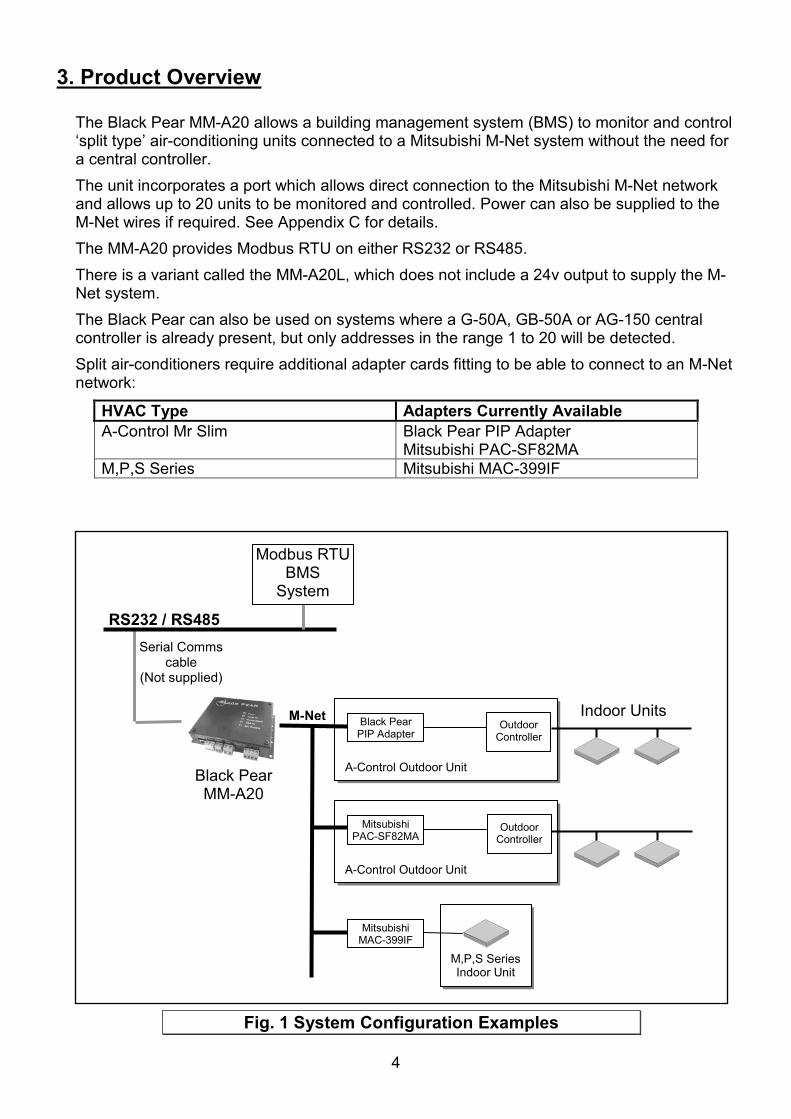
The Black Pear MM-A20 allows a building management system (BMS) to monitor and control ‘split type’ air-conditioning units connected to a Mitsubishi M-Net system without the need for a central controller. The unit incorporates a port which allows direct connection to the Mitsubishi M-Net network and allows up to 20 units to be monitored and controlled. Power can also be supplied to the M-Net wires if required. See Appendix C for details. The MM-A20 provides Modbus RTU on either RS232 or RS485. There is a variant called the MM-A20L, which does not include a 24v output to supply the M-Net system. The Black Pear can also be used on systems where a G-50A, GB-50A or AG-150 central controller is already present, but only addresses in the range 1 to 20 will be detected. Split air-conditioners require additional adapter cards fitting to be able to connect to an M-Net network:
HVAC Type Adapters Currently Available A-Control Mr Slim Black Pear PIP Adapter
Mitsubishi PAC-SF82MA M,P,S Series Mitsubishi MAC-399IF
M,P,S SeriesIndoor Unit
Mitsubishi MAC-399IF
A-Control Outdoor Unit
Mitsubishi PAC-SF82MA
Outdoor Controller
A-Control Outdoor Unit
Black Pear PIP Adapter
Outdoor Controller
RS232 / RS485
Black PearMM-A20
Indoor Units
Modbus RTUBMS
System
Serial Comms cable
(Not supplied)
M-Net
Fig. 1 System Configuration Examples
4
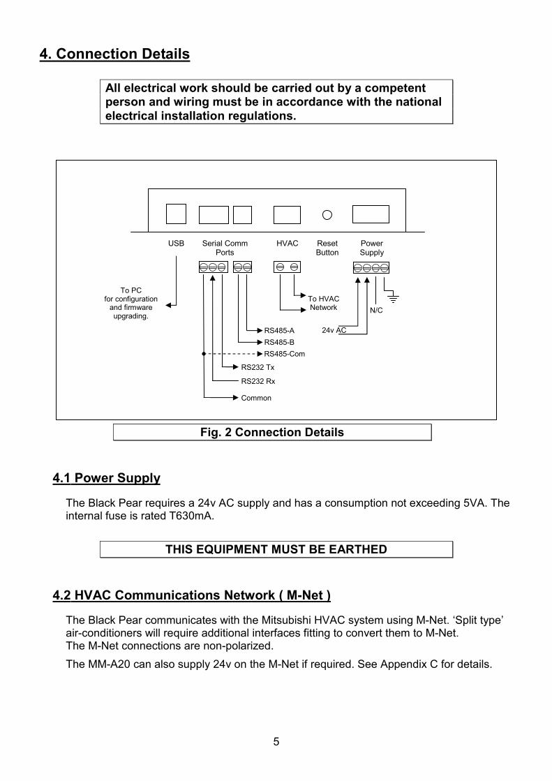
4. Connection Details
All electrical work should be carried out by a competent person and wiring must be in accordance with the national electrical installation regulations.
4.1 Power Supply
The Black Pear requires a 24v AC supply and has a consumption not exceeding 5VA. The internal fuse is rated T630mA.
THIS EQUIPMENT MUST BE EARTHED
4.2 HVAC Communications Network ( M-Net )
The Black Pear communicates with the Mitsubishi HVAC system using M-Net. ‘Split type’ air-conditioners will require additional interfaces fitting to convert them to M-Net. The M-Net connections are non-polarized. The MM-A20 can also supply 24v on the M-Net if required. See Appendix C for details.
ResetButton
PowerSupply
HVACSerial Comm Ports
24v AC
N/C
USB
RS485-B RS485-A
RS232 Tx
RS232 Rx
Common
To HVACNetwork
To PC for configuration
and firmware upgrading.
RS485-Com
Fig. 2 Connection Details
5
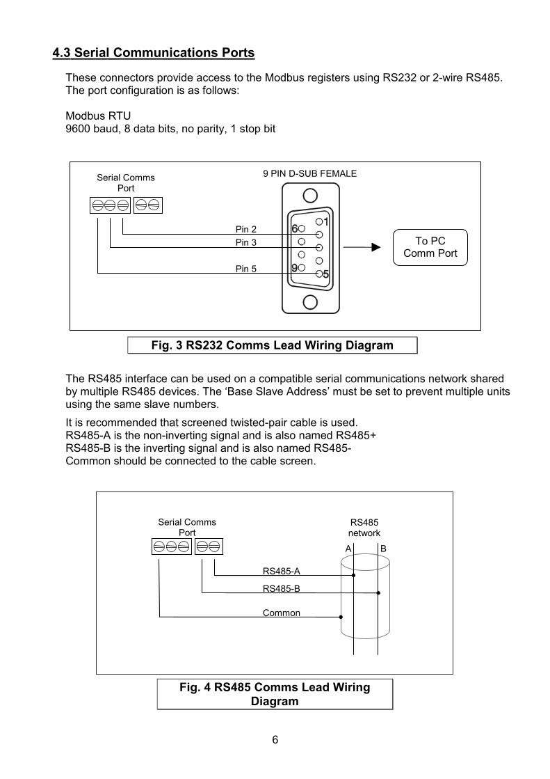
4.3 Serial Communications Ports
These connectors provide access to the Modbus registers using RS232 or 2-wire RS485. The port configuration is as follows: Modbus RTU 9600 baud, 8 data bits, no parity, 1 stop bit
TbuIRRC
Serial Comms Port
Pin 5
Pin 3 Pin 2
To PC Comm Port
9 PIN D-SUB FEMALE
Fig. 3 RS232 Comms Lead Wiring Diagram
he RS485 interface can be used on a compatible serial communications network shared y multiple RS485 devices. The ‘Base Slave Address’ must be set to prevent multiple units sing the same slave numbers.
t is recommended that screened twisted-pair cable is used. S485-A is the non-inverting signal and is also named RS485+ S485-B is the inverting signal and is also named RS485- ommon should be connected to the cable screen.
Serial Comms Port
RS485-B
RS485-A
RS485 network
Common
A B
Fig. 4 RS485 Comms Lead Wiring Diagram
6

7
4.4 USB
The USB interface is used for configuration via a PC and for upgrading the firmware. Requires a standard USB-A to USB-B cable (not supplied).
Ensure that the correct USB driver has been installed prior to connecting the Black Pear to a PC.

8
5.Air-Conditioning Group Configuration ( Mitsubishi )
IndoorUnit
Black Pear
M-Net
PIP Adapter01 TB1
A-Series Outdoor IndoorUnit
RemoteController
IndoorUnit
PIP Adapter02 TB1
A-Series Outdoor IndoorUnit
RemoteController
IndoorUnit
PIP Adapter03 TB1
A-Series Outdoor
RemoteController
IndoorUnit
PIP Adapter04 TB1
A-Series Outdoor IndoorUnit
RemoteController
Fig. 5 HVAC Example

9
The groupings determine which unit addresses can accept commands from the BMS system. The group number is defined as ‘the lowest indoor unit address within the group’. This then becomes the ‘master’ address for the group, and is the only address within that group that can accept commands. The other units within a group can be classed as ‘slave’ units and contain the same status parameter values as the ‘master’, apart from Return Air Temp and Error Code, which are unique to each unit.
Attempting to write a command to a ‘slave’ unit will have no effect.
In the example shown in Fig. 5, addresses 01, 02, 03 and 04 are available. Even though there are multiple indoor units attached to some of the outdoors, the Black Pear will treat each address as a single unit. It is possible to group these addresses within the Black Pear using the PC configuration software.
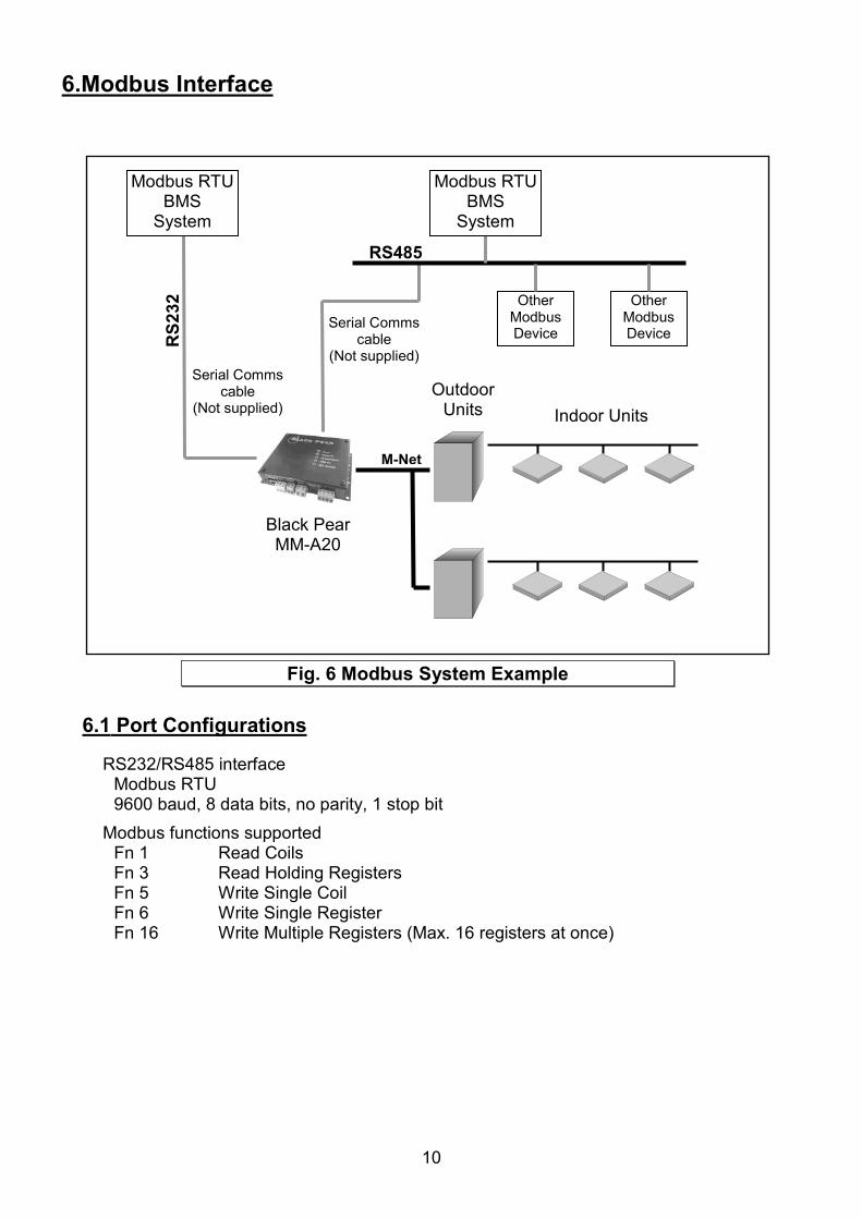
6.Modbus Interface
6
RS2
32
Black PearMM-A20
Outdoor Units Indoor Units
Modbus RTUBMS
System
Serial Comms cable
(Not supplied)
RS485
Modbus RTUBMS
System
Serial Comms cable
(Not supplied)
M-Net
Other Modbus Device
Other Modbus Device
Fig. 6 Modbus System Example
10
.1 Port Configurations
RS232/RS485 interface Modbus RTU 9600 baud, 8 data bits, no parity, 1 stop bit Modbus functions supported Fn 1 Read Coils Fn 3 Read Holding Registers Fn 5 Write Single Coil Fn 6 Write Single Register Fn 16 Write Multiple Registers (Max. 16 registers at once)

11
6.2 HVAC Status and Control Registers
The Black Pear MM-A20 behaves as 24 modbus slaves. Slaves 1 to 22 each have 90 registers (Offset = 0 to 89). Slaves 23 and 24 are used for configuration. Slaves 8 to 22 are not used by this version of the Black Pear. They are required for systems which have a maximum of 64 units. The default ‘Base Slave Address’ is 1, meaning the Black Pear will respond to msgs for slaves 1 to 24. The Base Slave Address can be adjusted from 1 up to 200. A setting of 200 means the Black Pear will respond to msgs for slaves 200 to 223. This is useful to prevent address clashing when the Black Pear unit is attached to a serial communications network containing multiple Modbus devices. Some BMS systems have limited slave address resources, so the ‘Single Slave Access’ feature means the Black Pear can be configured to respond to just 1 slave address (i.e. the ‘Base Slave Address’ setting). The Black Pear maps the data from the air conditioner units into Modbus registers accessed by two Modbus parameters ‘Slave No.’ and ‘Offset’. All slave numbers referred to in this document assume the default Base Address. Slaves 1 to 6 each represent 3 units, and slave 7 represents 2 units. Each slave is organised as follows:
General Information Extended Information Extra Information Unit A Unit B Unit C Unit A Unit B Unit C Unit A Unit B Unit C Offset 0 Offset 10 Offset 20 Offset 30 Offset 40 Offset 50 Offset 60 Offset 70 Offset 80
General information for a single unit
Extended information for a single unit
Extra information for a single unit
Register Offset Stored Value Register
Offset Stored Value Register Offset Stored Value
0 Return Air Temp 0 Air Direction (R) 0 Unused 1 Error Code 1 Air Direction (W) 1 Unused 2 Setpoint (R) 2 Inhibit (R) 2 Unused 3 Mode (R) 3 Inhibit (W) 3 Unused 4 Fan Speed (R) 4 Ventilation (R) � 4 Unused 5 Setpoint (W) 5 Ventilation (W) � 5 Unused 6 Mode (W) 6 Error Code (DispA) 6 Unused 7 Fan Speed (W) 7 Error Code (DispB) 7 Unused 8 On/Off (R) 8 CN32 state 8 Unused 9 On/Off (W) 9 Unused 9 Unused
See Section 6.5 for an overview of Modbus slave and offset usage..
Examples: 1) To read the current fan speed of unit 8
Single Slave Access = Off Single Slave Access = On Slave Function Offset Slave Function Offset
3 3 14 1 3 194
2) To read the current mode of unit 18
Single Slave Access = Off Single Slave Access = On Slave Function Offset Slave Function Offset
6 3 23 1 3 473
� Not currently supported

12
On/Off and Inhibit can also be accessed via ‘Coils’. Each slave contains 12 coils, organised as follows:
Coil Offset Definition 0 Unit A On/Off (R) 1 Unit A On/Off (W) 2 Unit B On/Off (R) 3 Unit B On/Off (W) 4 Unit C On/Off (R) 5 Unit C On/Off (W) 6 Unit A Inhibit (R) 7 Unit A Inhibit (W) 8 Unit B Inhibit (R) 9 Unit B Inhibit (W) 10 Unit C Inhibit (R) 11 Unit C Inhibit (W)
NoteCoil access is not available when ‘Single Slave Access’ is enabled.
6.3 Additional Register Usage
Slave Offset Single Slave Offset
Description Valid Settings
22 150 2040 HVAC Network Status 00: Waiting 01: Searching 02: Ready 03: Unknown
22 151 2041 System Force Off � 00: Not active 01: Active
See Appendix D for a description of the various settings.
� Not currently supported
13
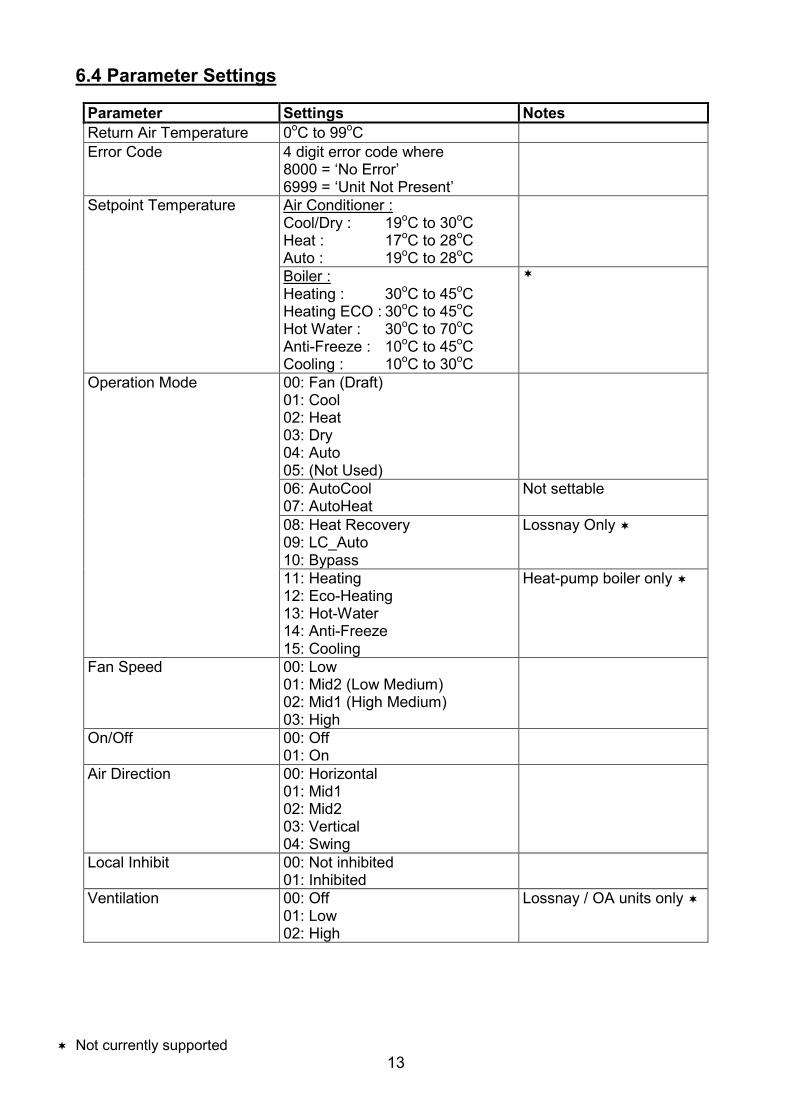
6.4 Parameter Settings
Parameter Settings Notes Return Air Temperature 0oC to 99oCError Code 4 digit error code where
8000 = ‘No Error’ 6999 = ‘Unit Not Present’
Setpoint Temperature Air Conditioner :Cool/Dry : 19oC to 30oCHeat : 17oC to 28oCAuto : 19oC to 28oCBoiler :Heating : 30oC to 45oCHeating ECO : 30oC to 45oCHot Water : 30oC to 70oCAnti-Freeze : 10oC to 45oCCooling : 10oC to 30oC
�
Operation Mode 00: Fan (Draft) 01: Cool 02: Heat 03: Dry 04: Auto 05: (Not Used)
06: AutoCool 07: AutoHeat
Not settable
08: Heat Recovery 09: LC_Auto 10: Bypass
Lossnay Only �
11: Heating 12: Eco-Heating 13: Hot-Water 14: Anti-Freeze 15: Cooling
Heat-pump boiler only �
Fan Speed 00: Low 01: Mid2 (Low Medium) 02: Mid1 (High Medium) 03: High
On/Off 00: Off 01: On
Air Direction 00: Horizontal 01: Mid1 02: Mid2 03: Vertical 04: Swing
Local Inhibit 00: Not inhibited 01: Inhibited
Ventilation 00: Off 01: Low 02: High
Lossnay / OA units only �
� Not currently supported

14
6.5 Modbus Table Overview
Single Slave Access Coil Base Offsets Unit
Address Slave General
Info Base Offset
Extended Info Base
Offset
Extra Info Base Offset
General Info Base
Offset
Extended Info Base
Offset On/Off Inhibit
1 1 0 30 60 0 30 0 62 1 10 40 70 10 40 2 83 1 20 50 80 20 50 4 10 4 2 0 30 60 90 120 0 65 2 10 40 70 100 130 2 86 2 20 50 80 110 140 4 10 7 3 0 30 60 180 210 0 68 3 10 40 70 190 220 2 89 3 20 50 80 200 230 4 10 10 4 0 30 60 270 300 0 611 4 10 40 70 280 310 2 812 4 20 50 80 290 320 4 10 13 5 0 30 60 360 390 0 614 5 10 40 70 370 400 2 815 5 20 50 80 380 410 4 10 16 6 0 30 60 450 480 0 617 6 10 40 70 460 490 2 818 6 20 50 80 470 500 4 10 19 7 0 30 60 540 570 0 620 7 10 40 70 550 580 2 8

15
Appendix A : Physical Dimensions
The holes marked ‘A’ should be used when mounting the enclosure on a back panel. The holes marked ‘B’ can be used to attach the supplied din-rail clips.
34mm
ResetButton
PowerSupply
HVACSerial Comm Ports
USB
144mm
117mm
A
A
A
A
B
B
B
B
135mm
Fig. 7 Dimensions
16
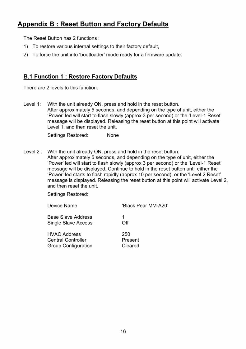
Appendix B : Reset Button and Factory Defaults
The Reset Button has 2 functions : 1) To restore various internal settings to their factory default, 2) To force the unit into ‘bootloader’ mode ready for a firmware update.
B.1 Function 1 : Restore Factory Defaults
There are 2 levels to this function. Level 1: With the unit already ON, press and hold in the reset button.
After approximately 5 seconds, and depending on the type of unit, either the ‘Power’ led will start to flash slowly (approx 3 per second) or the ‘Level-1 Reset’ message will be displayed. Releasing the reset button at this point will activate Level 1, and then reset the unit.
Settings Restored: None Level 2 : With the unit already ON, press and hold in the reset button.
After approximately 5 seconds, and depending on the type of unit, either the ‘Power’ led will start to flash slowly (approx 3 per second) or the ‘Level-1 Reset’ message will be displayed. Continue to hold in the reset button until either the ‘Power’ led starts to flash rapidly (approx 10 per second), or the ‘Level-2 Reset’ message is displayed. Releasing the reset button at this point will activate Level 2, and then reset the unit.
Settings Restored:
Device Name ‘Black Pear MM-A20’
Base Slave Address 1 Single Slave Access Off
HVAC Address 250 Central Controller Present Group Config uration Cleared

17
B.2 Function 2 : Enable ‘Bootloader’ Mode
Bootloader mode allows the firmware to be updated from a PC. Press and hold in the reset button while powering up the unit. Continue to hold in the reset button for approx. 5 seconds. The unit is now in bootloader mode.
Note:Enabling the bootloader in this way is only necessary if the firmware update software fails to automatically put the unit into bootloader mode.

Appendix C : Supplying 24v on M-Net
The MM-A20 can be configured to supply power to the M-Net wires if required.
Before enabling this feature, ensure that 24v isn’t already present on the M-Net cable. The Black Pear 24v output could be damaged if 24v
is already being supplied by another device.
Disconnect the supply before removing the top cover
The output should be disabled if the M-Net power is being supplied by an external device. The output should be enabled in all other cases.
Note: This also applies to the Black Pear MM-A20L. Even though the 24v output is not fitted, enabling the output also enables the filtering circuit.
*
v1 & v2 pcb : Shorting links (LK2)
v3 pcb : Bit Switches (S1)
Disabled *Enabled
Enabled Disabled *
ON
1 2OFF 1 2
M-Net Power Selection
NoteEnabling the power output also enables a filtering circuit.
Fig. 8 M-Net Power Output Configuration
18 Factory Default
19
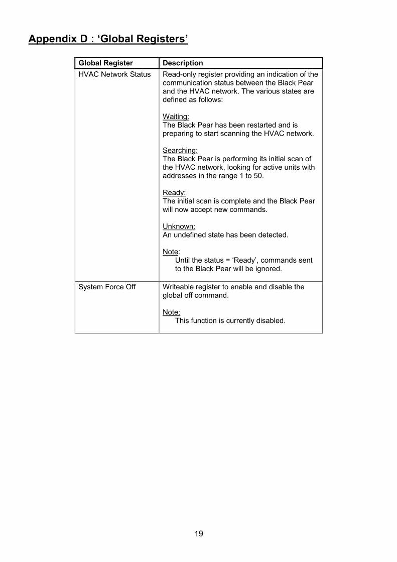
Appendix D : ‘Global Registers’
Global Register Description HVAC Network Status Read-only register providing an indication of the
communication status between the Black Pear and the HVAC network. The various states are defined as follows: Waiting:The Black Pear has been restarted and is preparing to start scanning the HVAC network. Searching:The Black Pear is performing its initial scan of the HVAC network, looking for active units with addresses in the range 1 to 50. Ready:The initial scan is complete and the Black Pear will now accept new commands. Unknown:An undefined state has been detected. Note:
Until the status = ‘Ready’, commands sent to the Black Pear will be ignored.
System Force Off Writeable register to enable and disable the
global off command. Note:
This function is currently disabled.

20
Appendix E : Document Revision History
Date Document Ver Firmware Ver By Comments 23/08/2013 v1.00 v2.04 mcb First complete version.
22/05/2014 v1.01 v2.18 mcb Important Information now includes comment about configuration software.

Notes

Microtrol Ltd 16 Elgar Business Centre Moseley Road Hallow Worcester WR2 6NJ UK Tel: +44 (0)1905 641910 Email: [email protected]