mmoo ppaarr - freakride.com ppaarr e-body 1970-74 4-link ... your rear suspension system arrives...
TRANSCRIPT

MMMOOOPPPAAARRR E-BODY 1970-74 4-LINK
PARALLEL SYSTEM W/TRACK BAR
INSTRUCTIONS
4-Link Parallel With Track Bar
Rear Suspension Systems
FOR MOPAR MUSCLE CARS: 1970-1974 E-BODY (RS-5490)
Revised: 7-1-2012

Page 2

Page 3

Page 4
Installation Instructions Triangulated 4-Link Rear Suspension System – Part # RS-5490
Mopar E-Body Vehicles
System Contents
Forward Trailing Link Brackets (1 Left and 1 Right)
Forward Through-Frame Brackets (2)
Lower Rear Trailing Link Brackets (2)
Upper Rear Trailing Arm Differential Mount (2)
Lower Trailing Arm Set w/Adjustable Rod Ends
Lower Trailing Arm Mounting Hardware Kit
Upper Trailing Arm Set w/Adjustable Rod Ends
Upper Trailing Arm Mounting Hardware Kit
Upper Coil Over Mount Brackets (1 Left and 1 Right)
Lower Coil Over Mount Brackets With Hardware (2)
Coil Over Shocks w/ Springs (2 Each)
Coil Over Mounting Hardware Kit
Track Bar with Brackets & Adjustable Rod Ends (2)
Thank you for purchasing this Parallel 4-Link Rear Suspension System for
Mopar E-Body Vehicles. This system is manufactured by Control Freak Suspensions™
in
Winter Springs, Florida. We believe this system is the best available at any price. As
with most aftermarket performance suspension products, the end user is solely
responsible for determining the suitability of any and all such products, regardless of
manufacturer.
Because this system, and others like it, are typically subjected to uses that could exceed
its mechanical limits, there is no warranty, expressed or implied. Blue Moon Services
LLC d/b/a Control Freak Suspensions™
cannot control how this product is installed or
used. By purchasing this product you are assuming all risks associated with its
installation and use and agree to having appropriate skills for its installation and use.
Blue Moon Services LLC d/b/a Control Freak Suspensions™
, our vendors and suppliers
will not be held responsible, liable or accountable for any injury, damage, loss, penalties
or fines that occur, directly or indirectly, from the installation and use of this product.
Please note that this system includes components that must be welded accurately into
place. While installation is relatively easy for those with appropriate skills and
experience, novices, or those who question their abilities, should employ a professional
for installation. Fit is guaranteed on vehicles that are unmolested…that is cars that have
not suffered any chassis or unitized body damage. Such damage can bend or alter the
unitized chassis, making installation more difficult and may require chassis adjustment
and/or straightening by professionals before installation.

Page 5
Read all of the instructions before starting installation.
IMPORTANT NOTES:
1. All brackets in this kit must be welded into place.
2. Be certain to remove carpeting, insulation or other flammables from the area
being welded or subjected to welding heat.
3. Installation of this rear suspension system is straightforward, but ease of
installation is based upon your level of experience and ability.
4. By following these instructions and measuring accurately, we strongly
recommend that all welded parts get tack welded into place prior to final
welding. This allows you to fit the entire system before final welding is done.
5. Some parts of this system may have been accurately threaded by our CNC
machine shop to receive the supplied adjustable rod and/or bushing ends. Be
careful not to cross thread the rod ends into these machined parts. Use anti-seize
compound on all threaded parts. We are not responsible for any cross threaded
parts.
6. All rod ends that are threaded into tubes must use the supplied jam nuts for safety.
7. Use extra caution in jacking and stabilizing the vehicle for this installation. The
differential will need to be removed and reinstalled, so we strongly recommend
the use of a professional lift to make the job easier and safer.
8. An assistant is recommended during parts of this installation.
What Else Do I Need?
Everything you need is included in the purchase price. Installation requires welding.
Disconnect your battery BEFORE welding. If you don’t, you run the risk of ruining
electronic ignition and entertainment components in the car.
. IMPORTANT NOTES:
Unpacking the System
Your rear suspension system arrives boxed but only partially assembled. Since this
system requires all brackets to be welded into place we are unable to pre-assemble much
of the product. While some parts may arrive assembled, please note that the assembled
parts may not be appropriately installed or tightened for actual use. You are responsible
for making certain all fasteners are installed correctly and appropriately tightened. If you
ordered brakes with your system, the brake kit is boxed separately and has its own set of
instructions provided by brake manufacturer.

Page 6
Carefully open all boxes and remove all components. Lay out all of the components and
familiarize yourself with them using the CAD drawings on page 2 as your guide. This
will make installation quicker and easier. Read through the entire instruction book and
familiarize yourself with the steps before beginning installation.
Once you have read through the instructions and identified all of the parts, prepare your
tools for installation. You are now ready to begin installation.
Preparing for Installation
1. Measure the ride height of the vehicle by taking measurements from the rocker
panel to the ground. Take a front and rear measurement on each side and note it in
a notebook. We recommend using masking tape at all four measuring points and
writing the measurement so it can always be seen. This is your baseline stock ride
height.
2. Support the differential with jacks. If you are using a lift, support with tall jacks.
With the differential safely supported, remove the sway bar and the end brackets
holding it in place against the frame.
3. Remove any exhaust components that may interfere with removing the rear
differential.
4. Disconnect the driveshaft from the differential.
5. Remove the shocks from both sides of the differential.
6. Making certain the differential is supported by jacks, with a helper remove the
front and rear leaf spring bolts, keeping the differential from turning while doing
so. You will remove the entire differential assembly.
7. Once the differential has been removed, take this opportunity to clean it up. After
the upper and lower trailing arm brackets have been welded into place, and the
original spring perches removed (if you choose to do so), you can paint the rear
before reinstalling with the new suspension system.
8. Examine the rails on the car. Over the years, the
vehicle may have been incorrectly jacked up in some
areas which can slightly “mushroom” or otherwise
move the rails slightly out of line. This is an
opportunity to straighten or adjust the rails prior to
putting the rear suspension brackets in place.
9. Prior to installing the brackets, the area around each
bracket must be sanded to raw metal and cleaned. We
use an air die grinder with a 3” RoLok sanding disc. 80 grit works fine. Clean at
least 1/2” beyond the bracket, leaving ample clean metal for a good weld.

Page 7
The picture to the left shows the forward
frame bracket on the outside of the rail,
firmly against the sheet metal lip of the
forward leaf spring mount. Do this on
both sides then measure each brackets
distance from a fixed point on each side of
the chassis. Make fine adjustments to
ensure they are positioned at equal
distances and square.
Installation of the Rear Suspension Brackets
1. Place the forward frame brackets into place. There is a right and left bracket.
Correct placement is shown from the outside of the rail in the photos above.
Make certain the area around the perimeter is cleaned to bare metal allowing a
good welding surface. The forward edge of the brackets should be perpendicular
to the chassis.
2. On the inside of the rail locate the upper trailing arm mount on the forward frame
bracket you just tack welded into position. Drill a 3/16” hole through the center
of the trailing arm mounting holes and through the chassis rail. From the outside
of the chassis enlarge the hole to 1-1/8” with either a drill bit or a die grinder.
Once done, insert the standoff into the hole and run the upper tailing arm
mounting bolt through the holes and all the way through the standoff. Tack weld
the plate into position on the outside of the rail.
3. Get both upper and lower trailing arms and screw the rod ends in until about three
threads are showing between the jam nut and the body of the rod end. Only hand
tighten the jam nut. The length of both upper trailing arms should match each
other as should the lower trailing arms.
4. Attach the upper and lower trailing arms to the forward frame brackets. Hand
tighten the bolts.
5. Attach the rear lower trailing arm brackets to the lower trailing arms. Only hand
tighten the bolts. Attach the upper trailing arm to the smaller upper trailing arm
brackets. Hand tighten the bolts. This provides ease for the initial tack weld
position for the upper and lower trailing arm brackets on the differential.

Page 8
6. Move the differential into position making certain that it is centered between the
rails and at the ride height you have chosen. Now adjust the height of the rear axle
to your desired ride height, which is typically 12-13” between the upper and lower
shock mounts. Ride height is entirely up to you and the look / stance you want the
car to have. You also must consider tire size. At this time, you should set a rough
pinion angle before locating the upper & lower mounts. If you can get to it, hold an
angle finder on the crank pulley and note the angle. If you cant get into the crank
pulley area with an angle finder, use the angle of the transmission tailshaft. Now
place the angle finder on the front of the rear axle pinion and rotate the axle to
duplicate the same angle. Placing the differential on two (2) jack stands and using a
floor jack to adjust the angle is the simplest way to make even fine adjustments. Set
the pinion angle from zero degrees to minus one-half degree.
7. Place the brackets that are attached to the lower trailing arms onto the differential.
When you are satisfied that the brackets are in the appropriate location and
perpendicular to the differential axle tubes, place a tack weld in the corners of the
brackets just to hold them into position. If you need to make an adjustment later
you will only have to cut through a few tack welds.
8. Place the upper trailing arm differential brackets into position on the top of the
differential tubes. You can see the position by viewing the CAD drawing on page
2. Just like on the lower brackets, tack the upper brackets into position ensuring
they are parallel with the lower trailing arms and perpendicular to the differential
axle tubes. Place a few tack welds into the corners of the brackets.
9. Attach the lower coil over mount brackets to the lower trailing arm brackets on
the differential tubes. Snug the nuts but do not torque them.
10. Prepare the vehicle for installation of the upper coil over mounts. This step will
require a little fabrication and some minor cutting
of the edge of a sheet metal bracket. The first
picture shows where to mark the sheet metal to
trip it. You can use the bracket as a template to
get a nice, even cut. The second picture shows the
sheet metal after trimming. We use an air die
grinder with a 3” cutting wheel. Regardless of
what you use, make sure you have the right lines
before cutting. Measure twice. Be certain to wear
safety equipment such as face shield, eye
protection and leather welding gloves.

Page 9
11. Place the left and right upper coil over brackets into position as shown in the
pictures above. Carefully tack weld the parts into place by placing tack welds
where you can get to them should you need to shift bracket position. Again,
double check before placing the tack welds. It is better to get it right the first
time, even if it takes longer to do.
12. After checking all of the tack welds, and being sure that everything is evenly
installed, you can remove the trailing arms.
13. Carefully, and with the aid of a
helper, remove the differential
from under the vehicle and
prepare it for final welding of
the brackets.
14. Before welding brackets to the
differential, loosen the axles so
heat does not build up and melt
the axle seals. Weld a little at a
time and alternate from side to
side. We prefer to turn the differwential upside dow, making it easier to get a
good, clean weld.
15. Weld all of the tack welded brackets and parts under the vehicle into place.
NOTE: Before final welding of the under-vehicle parts, remove carpeting
and anything flammable from the interior of the vehicle.
16. Once welded and cooled, take the opportunity to
prime and paint the welded brackets and the areas
around the welds.
17. The differential snubbers that are located on either
side of the vehicle on the upper part of the chassis rail
can now be trimmed. You will leave about 1” of the
snubber in place. The cut is easily made with a hack
saw as shown in the picture.
Page 10
18. You can now reinstall the trailing arms and differential, making certain to tighten
all bolts.
19. Prepare the coil over shocks for assembly. Paint some silver anti-seize compound
onto the bottom half of the threads on the coil over body. This will ensure than
when the coil over is assembled and under load that the nut will still turn without
galling. Thread the lower nut onto the body, install the spring and attach the hat
to hold the spring.
20. Install the coil over shocks. We recommend adjusting the coil over shocks with
about ½” to ¾” of threads showing under the nut on the coil over body as a
starting point. Coil overs will settle about ¾” after ten or fifteen miles of driving.
So set the height of your vehicle about ¾” higher than you want it. It will settle.
21. The last piece to install is the track bar with its two brackets. The brackets attach
to the inside of the right rear lower trailing arm mount, and to the left front lower
trailing arm mount, forming a diagonal under the differential.
22. You can now put the vehicle on the ground.
23. That’s it. You are done. Drive carefully.
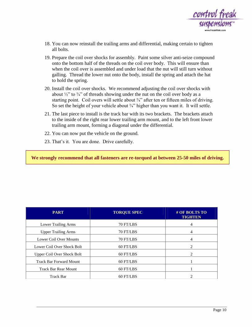
PART TORQUE SPEC # OF BOLTS TO
TIGHTEN
Lower Trailing Arms 70 FT/LBS 4
Upper Trailing Arms 70 FT/LBS 4
Lower Coil Over Mounts 70 FT/LBS 4
Lower Coil Over Shock Bolt 60 FT/LBS 2
Upper Coil Over Shock Bolt 60 FT/LBS 2
Track Bar Forward Mount 60 FT/LBS 1
Track Bar Rear Mount 60 FT/LBS 1
Track Bar 60 FT/LBS 2
We strongly recommend that all fasteners are re-torqued at between 25-50 miles of driving.

Page 11
Disclaimer of Warranty
THE PURCHASER IS RESPONSIBLE FOR DETERMINING THE SUITABILITY OF ANY AND ALL PRODUCTS
MANUFACTURED BY CONTROL FREAK SUSPENSIONS
Purchaser understands and recognizes that racing parts equipment and services provided
by, manufactured and/or sold by Blue Moon Services LLC d/b/a Control Freak
Suspensions under the Control Freak Suspensions label, are subject to varied conditions
due to the manner in which they are installed and used. Purchaser further recognizes and
agrees that suitability of any part sold or manufactured by Blue Moon Services LLC d/b/a
Control Freak Suspensions under the Control Freak Suspensions label for a particular
application is the purchasers decision and that the purchaser is not relying on the skill or
judgment of Blue Moon Services LLC d/b/a Control Freak Suspensions under the Control
Freak Suspensions label regarding suitability of any product or service. Blue Moon
Services LLC d/b/a Control Freak Suspensions under the Control Freak Suspensions
label, makes no warranties whatsoever, expressed or implied, oral or written to
purchasers. There is no warranty of merchantability made to purchasers with regard to off
road, racing and racing equipment.
Liability is limited to repair or replacement of defective parts to original purchaser. Blue
Moon Services LLC d/b/a Control Freak Suspensions is not liable for any consequential
damages, expenses or injury arising from the use, misuse, or improper installation of any
product manufactured or sold by Blue Moon Services LLC d/b/a Control Freak
Suspensions under the Control Freak Suspensions label. Blue Moon Services LLC d/b/a
Control Freak Suspensions reserves the right to make changes in design or add to or
improve its product without incurring any obligation to install the same on any products
previously manufactured. This warranty shall not apply to any product which has been
repaired or altered in any way so as in our judgment to affect its performance; nor which
has been subject to misuse, abuse, negligence or any other occurrence beyond the control
of Blue Moon Services LLC d/b/a Control Freak Suspensions.

Page 12
Control Freak Suspensions™
1101 Oak Lane, Suite 1031
Winter Springs, Florida 32708
Toll Free: (888) 325-6462
Direct: (407) 696-2772
Fax: (407) 696-6216
www.FreakRide.com
MMMOOOPPPAAARRR E-BODY 1970-74 4-LINK
PARALLEL SYSTEM W/TRACK BAR