mns - abb group · – starters and distribution units of withdrawable design ... roof plate:...
TRANSCRIPT

ABB Installation
Low-voltage switchgear MNS Installation, handlingand operation
MNS

2
Low-voltage switchgear MNS is available with rated currents up to5000 A (IP 31) and can be equipped with:– starters and distribution units of withdrawable design (W units)– distribution units and group boards of removable design (R units)
List of contentsHandling and unpacking page 3
Setting up switchgear cubicles 4
Laying of external cables 6
Connection of circuit-breaker cubicle and disconnector cubicle 7Disconnector cubicle, cable connection from below 7Disconnector cubicle, busbar connection from above 7Circuit-breaker cubicle, cable connection from below 8Circuit-breaker cubicle, cable connection from above 10Circuit-breaker cubicle, busbar connection from above 12
Connection of apparatus unitsWithdrawable units, main circuits 14Removable units, main circuits 16Screw-in fuse boards 17MCB boards 20Auxiliary circuits 21Protective earthing 21
Withdrawable apparatus units, handlingDescription 22Operation 23Withdrawing 25Inserting 26Extension 27
Withdrawable apparatus units, handlingDescription 28Operation 28Replaceability, MNS – Center 5000/1600 28Removing a unit 29Mounting a unit 29Extension 30
Measures to be adopted before applying voltageConcluding work 31Check list upon commissioning 31
3
Handling and unpacking
The switchgear cubicles are delivered in the form of readyassembled complete units with horizontal busbars. Eachcubicle is protected with plastic wrapping and securelyattached to a loading pallet.
Check the delivery against the accompanying advice note.
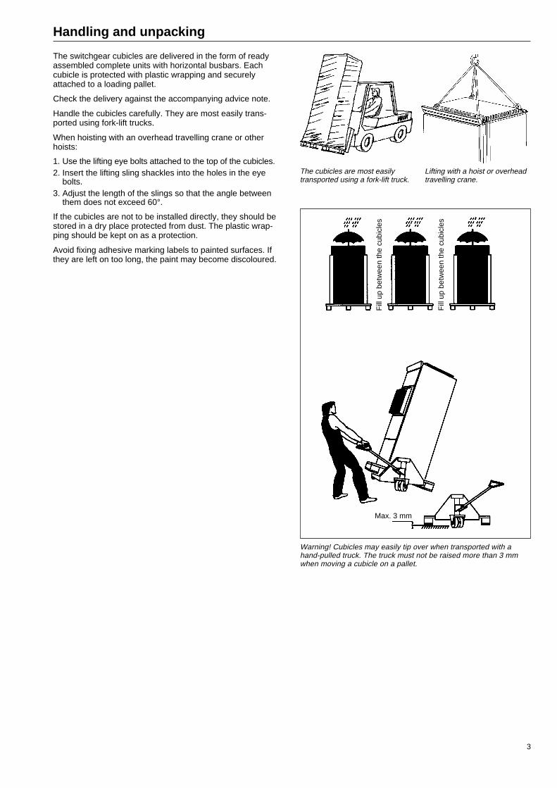
Handle the cubicles carefully. They are most easily trans-ported using fork-lift trucks.
When hoisting with an overhead travelling crane or otherhoists:
1. Use the lifting eye bolts attached to the top of the cubicles.2. Insert the lifting sling shackles into the holes in the eye
bolts.3. Adjust the length of the slings so that the angle between
them does not exceed 60°.
If the cubicles are not to be installed directly, they should bestored in a dry place protected from dust. The plastic wrap-ping should be kept on as a protection.
Avoid fixing adhesive marking labels to painted surfaces. Ifthey are left on too long, the paint may become discoloured.
The cubicles are most easilytransported using a fork-lift truck.
Lifting with a hoist or overheadtravelling crane.
Fill
up
betw
een
the
cubi
cles
Fill
up
betw
een
the
cubi
cles
Max. 3 mm
Warning! Cubicles may easily tip over when transported with ahand-pulled truck. The truck must not be raised more than 3 mmwhen moving a cubicle on a pallet.

4
Setting up switchgear cubicles
Cubicle types, overviewCircuit-breaker cubicle for ACBCubicle widths up to 1200 mm.
Disconnector cubicleCubicle width 800 mm.
Apparatus cubicle W/RCubicle width 600 + 400 or 600 + 600 mm.
Apparatus cubicle for free equippingCubicle width 400, 600 or 800 mm.
The following dimensions are the same for all types of MNS cubicles:Height 2263 mmHeight module 50 mmDepth 650 mm
Clear space around cubiclesThe area around the cubicles to be left clear should be at least 150 mm.
The distance between the cubicle´s rear panel and the wall, and between endpanels and the wall, should be at least 40 mm.
Apparatus cubicles with operating handles in the doors should be placed with aclearance distance of at least 150 mm from the left end panel to the adjacent wallso that the doors can be opened more than 90°.
Drilling of holesThe drawings show the holes that can be drilled for external cables under thecubicles, in the base plate and in the roof plate.
min 150
Free space above cubicle.
min 40
min 40 – 150
Distance to wall.
Drilling of holes in floor and base plate:Circuit-breaker cubicle, b = 600, 800, 1000, 1200Disconnector cubicle, b = 600, 800Apparatus cubicle, b = 400, 600, 800
*) Not to be used when a cubicle is fixed toa wall.
Drilling of holes inroof plate:Apparatus cubicle, b = 400
Drilling of holes in roof plate:Apparatus cubicle W, b = 600 + 600
200
75
600
b
50
50*)
D=16
270
117
50
b – 100 50
Front
*)
50
Drilling of holes in floor and base plate:Apparatus cubicle W, b = 600 + 400, 600 + 800*) Not to be used when a cubicle is fixed to
a wall.
100
FL 21
100
150
216 130Front
Drilling of holes inroof plate:Apparatus cubicle, b = 600
Drilling of holes in roof plate:Apparatus cubicle W, b = 600 + 400
100
FL 21
100
150
200Front
100
FL 21
100
150
216 192Front
216
100
FL 21
100
150
216 184Front
216
100
FL 21
100
150
216 130Front
Drilling of holes inroof plate:Apparatus cubicle, b = 800
200
75
600
1000/1200
270
117
300/500 50
Front
50
50*)
50*)
50

5
Setting up switchgear cubicles (cont.)
Alignment of cubiclesThe flooring should be flat and even and carefully chosen for cubicle erectionso that several cubicles can be bolted together without necessitating further meas-ures.
If the floor is not sufficiently flat, this may result in panels and doors jamming.The height of the cubicles can be adjusted by inserting sheet metal shims betweenbase plate and floor.
Bolting together of cubiclesAny height adjustment of cubicles necessary must be carried out before boltingthem together.
At the front, the frames are to be bolted together at four places: There are fourclearance holes for M6 hexagonal headed bolts in the front right-hand frame postof cubicles, and corresponding threaded holes (ready-mounted threaded bushings)in the left hand post. The threaded holes are located 112.5 mm, 762.5 mm, 1437.5 mmand 2087.5 mm above the floor plane.
At the rear, the frames are bolted together at three places: 112.5, 2087.5 anddepending on whether the cubicles are fitted with an upper or lower busbar system,the frames are bolted together 762.5 mm (upper busbar system) or 1437.5 mm(lower busbar system) above the floor plane.
The maximum tightening torque is 5 Nm.
Five distance bolts (article no. 1TSA2 21671-90) for bolting cubicles together areprovided in a plastic bag to be found attached in the cable compartment of eachcubicle.
AttachmentPlacing against a wallThe cubicle furthest to the left in a row of cubicles is to be fixed to the wall with thehelp of two wall attachment brackets and to the floor with a bolt through the front ofits base plate, positioned 200 mm from the right-hand side of the cubicle. Othercubicles in the row are to be fixed to the wall with one wall attachment bracket andto the floor with a bolt through the front of their base plates.
Free-standing arrangementThe cubicle furthest to the left in a row of cubicles is to be fixed to the floor usingtwo bolts through the rear of its base plate (after removing the rear panel), 50 mmfrom the sides of the cubicle, and with a bolt through the front of its base plate,200 mm from the right-hand side of the cubicle. Other cubicles in the row are to befixed with one bolt through the rear of their base plates (after removing the rearpanel), 50 mm from the right-hand side of the cubicle, and with a bolt through thefront of their base plates, 200 mm from the right-hand side of the cubicle.
Recommended screw diameter: 10 mm.
Interconnection ot horizontal busbarsConnection of the horizontal busbars between the cubicle units should take placefrom the front of the cubicles.
1. Remove the polycarbonate shields in front of the bars to allow access to thepoint of interconnection.
2. Unscrew the bolts in the joint pieces.3. Move over the joint pieces to the bars in the cubicle alongside.4. Tighten the bolts with a torque wrench, 20 Nm.5. Fit the polycarbonate shields back on.
In the case of several parallel phase bars, the joint pieces should be placed asshown in the diagram.
Bolting cubicles together.
Coupling of phase bars. Coupling of N and PE bars.
Removal of polycarbonate shields.
D=1625
2315
31.5*)
Placing against a wall.
*) Only for the cubicle furthest to the left.

6
Laying of external cables
Apparatus cubicleAll external cables to apparatus cubicles are to be laid in the area intended forcables.
Main cablesIn the 400 mm cable compartment there are five rails on the right-hand cubiclewall, for fixing of main cables using cable hangers. Slimmer cables are best fixedto the rails by crossing two smaller bunching straps.
In the 600 mm cable compartment there are in addition five rails on the rear wall,for fixing of main cables.
Auxiliary cablesInternal wiring and operating voltage supply cables should be attached usingbunching straps in special attachment holes to the left at the rear of the cablecompartment. Control cables should be attached using strap attachments andbunching straps on the rear wall. (Bunching straps are delivered with the cubicles.)
For withdrawable units, there is a strap attachment on the right hand side of thecassette plate for supporting the weight of the operating cables.
Under the top door there is a cable duct intended for connections betweencubicles. The cable duct also serves as an attachment rail for cubicle terminalboards.
Cable compartment.
*) Only with 600 mm cable compartment.
Cable clamping straps.
Strap attachment.
Circuit breaker cubicles, disconnector cubicles, cubicles for extra equipmentMain cablesThe main cables are supported with fixing clamps in anchoring rails whichcan be attached in depth at different levels and matched to terminal bars andcables.
Auxiliary cablesOperating cables are supported with bunching straps in the cable bracketsfixed to the ends of the cubicle. Operating cables can be placed on eitherside, depending on where the terminal board is placed.
Cable duct for operating cables between cubicles. Attachment rail for cubicle terminal boards.
Maincables *)
Main cables
Control cables
Internal wiring
7
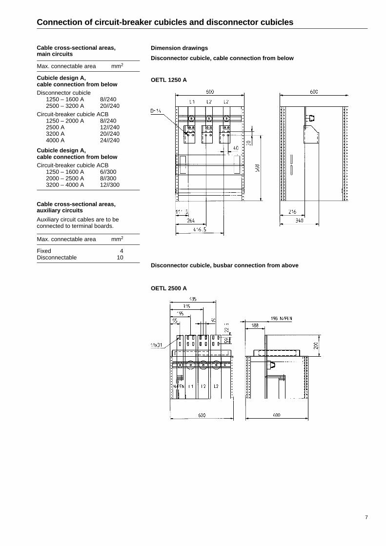
Connection of circuit-breaker cubicles and disconnector cubicles
Cable cross-sectional areas,main circuits
Max. connectable area mm2
Cubicle design A,cable connection from belowDisconnector cubicle
1250 – 1600 A 8//2402500 – 3200 A 20//240
Circuit-breaker cubicle ACB1250 – 2000 A 8//2402500 A 12//2403200 A 20//2404000 A 24//240
Cubicle design A,cable connection from belowCircuit-breaker cubicle ACB
1250 – 1600 A 6//3002000 – 2500 A 8//3003200 – 4000 A 12//300
Dimension drawings
Disconnector cubicle, cable connection from below
OETL 1250 A
Cable cross-sectional areas,auxiliary circuits
Auxiliary circuit cables are to beconnected to terminal boards.
Max. connectable area mm2
Fixed 4Disconnectable 10
OETL 2500 A
Disconnector cubicle, busbar connection from above

8
Connection of circuit-breaker cubicles and disconnector cubicles (cont.)
Dimension drawings
Circuit-breaker cubicle, cable connection from below
MEGAMAX 1250 A 3-P MEGAMAX 1250 A 4-P
MEGAMAX 1600 A 3-P MEGAMAX 1600 A 4-P
MEGAMAX 2000 A 3-P MEGAMAX 2000 A 4-P

9
MEGAMAX 2500 A 3-P MEGAMAX 2500 A 4-P
MEGAMAX 3200 A 3-P MEGAMAX 3200 A 4-P
MEGAMAX 4000 A 3-P MEGAMAX 4000 4-P
Connection of circuit-breaker cubicles and disconnector cubicles (cont.)
Dimension drawings
Circuit-breaker cubicle, cable connection from below

10
MEGAMAX 1250 A 3-P MEGAMAX 1250 A 4-P
MEGAMAX 1600 A 3-P MEGAMAX 1600 A 4-P
MEGAMAX 2000 A 3-P MEGAMAX 2000 A 4-P
*) Only when connection is made with a 5-conductor system.
*)
*)
*)
Connection of circuit-breaker cubicles and disconnector cubicles (cont.)
Dimension drawings
Circuit-breaker cubicle, cable connection from above

11
MEGAMAX 2500 A 3-P MEGAMAX 2500 A 4-P
MEGAMAX 3200 A 4-P
MEGAMAX 4000 A 3-P MEGAMAX 4000 A 4-P
*) Only when connection is made with a 5-conductor system.
*)
MEGAMAX 3200 A 3-P
*)
*)
Connection of circuit-breaker cubicles and disconnector cubicles (cont.)
Dimension drawings
Circuit-breaker cubicle, cable connection from above

12
Connection of circuit-breaker cubicles and disconnector cubicles (cont.)
Dimension drawings
Circuit-breaker cubicle, busbar connection from above
MEGAMAX 1250 A 3-P MEGAMAX 1250 A 4-P
MEGAMAX 1600 A 3-P MEGAMAX 1600 A 4-P
MEGAMAX 2000 A 3-P MEGAMAX 2000 A 4-P
*) Only when connection is made with a 5-conductor system.
*)
*)
*)

13
MEGAMAX 2500 A 3-P MEGAMAX 2500 A 4-P
MEGAMAX 3200 A 3-P MEGAMAX 3200 A 4-P
MEGAMAX 4000 A 3-P MEGAMAX 4000 A 4-P
Connection of circuit-breaker cubicles and disconnector cubicles (cont.)
Dimension drawings
Circuit-breaker cubicle, busbar connection from above
*)
*)
*)
*) Only when connection is made with a 5-conductor system.

14
Connection of apparatus units
Max connectable area 1 x 25 mm2
Connection unit for main circuits.Phase interval = 18 mm.
Withdrawable apparatus units 4 M/4, main circuits
Max connectable area 1 x 10 mm2
Withdrawable apparatus units 2 M, main circuits
Requisite screwdriver size for connection unit's clamp
Dimension A max. 235 mmB min 80 mmC 1.0 mmD 5.5 mm
D
B
C
A
Main circuitterminal boards

15
Connection of apparatus units (cont.)
Connection unit Max. connectable Max. bolt Max. tightening Cable shieldssize area dimension torque per phase
3 x 160 A (25 mm) 1 x 120 mm2 M10 x 30 45 Nm 1 x 120 mm2
6 x 160 A (25 mm) 1 x 120 mm2 M10 x 30 45 Nm 1 x 120 mm2
3 x 400 A (40 mm) 2 x 240 mm2 M12 x 35 80 Nm 2 x 240 mm2
Withdrawable apparatus units 8 M - 12 M > 400 A, main circuits
Connection unit Max. connectable Max. bolt Max. tighteningsize area dimension torque
3 x 800 A 4 x 240 mm2 M 12 x 35 80 Nm
Withdrawable apparatus units 4 M - 12 M ≤ 400 A, main circuits
Connection unit for main circuits.The cable shield protecting against inadvertent touchingshould be cut to fit the cable area. The shield should besecured with a clamping strap.
Connection unit for main circuits.The cable shield protecting against inadvertent touchingshould be cut to fit the cable area. The shield should besecured with a clamping strap.

16
Connection of apparatus units (cont.)
Apparatus unit Connectable area, copper cable Connectable area, aluminium cable
Type Size Min. area Max. area Max. area Min. area Max. area Max. areacable lug cable clamp cable lug cable clamp
mm2 mm2 mm2 mm2 mm2 mm2
MCCB ISOMAX N, fixedS3N 160 19 – 100 A 16 – 25 2//95 120 16 – 35 70 70S3N 160 88 – 160 A 35 – 50 2//95 120 50 – 70 2//150 120S3N 250 140 – 250 A 50 – 95 2//95 120 120 – 150 2//150 -S4N 250 40 – 250 A 25 – 95 2//95 120 120 – 150 2//150 -S5N 400 130 – 400 A 35 – 240 2//150 300 240 – 300 2//240 300S6N 630 250 – 630 A 1x95 – 2//150 3//300 2//300 2//240 3//240 2//300S6N 800 320 – 800 A 1x150 – 2//240 3//300 2//300 2//300 3//240 2//300
MCCB ISOMAX N, plug-inS3N 160 19 – 100 A 16 – 25 50 - 16 – 35 70 -S3N 160 88 – 160 A 35 – 50 2//95 - 50 – 70 2//150 -S3N 250 140 – 250 A 50 – 95 2//95 - 120 – 150 2//150 -S4N 250 40 – 250 A 25 – 95 2//95 - 120 – 150 2//150 -S5N 400 130 – 400 A 35 – 240 2//150 - 240 – 300 2//240 -S6N 630 250 – 630 A 1x95 – 2//150 3//300 2//300 2//240 3//240 2//300S6N 800 320 – 800 A 1x150 – 2//240 3//300 2//300 2//300 3//240 2//300
MCCB ISOMAX H, fixedS3H 160 19 – 100 A 25 2//95 120 25 – 35 2//150 120S3H 160 88 – 160 A 35 – 50 2//95 120 70 2//150 120S3H 250 140 – 250 A 50 – 95 2//95 120 120 – 150 2//150 -S4H 250 40 – 250 A 25 – 95 2//95 120 120 – 150 2//150 -S5H 400 130 – 400 A 35 – 240 2//185 300 240 – 300 2//240 300S6H 630 250 – 630 A 1x95 – 2//150 3//300 2//300 2//240 3//240 2//300S6H 800 320 – 800 A 1x150 – 2//240 3//300 2//300 2//300 3//240 2//300
MCCB ISOMAX H, plug-inS3H 160 19 – 100 A 25 70 - 25 – 35 70 -S3H 160 88 – 160 A 35 – 50 2//95 - 70 2//150 -S3H 250 140 – 250 A 50 – 95 2//95 - 120 – 150 2//150 -S4H 250 40 – 250 A 25 – 95 2//95 - 120 – 150 2//150 -S5H 400 130 – 400 A 35 – 240 2//185 - 240 – 300 2//240 -S6H 630 250 – 630 A 1x95 – 2//150 3//300 2//300 2//240 3//240 2//300S6H 800 320 – 800 A 1x150 – 2//240 3//300 2//300 2//300 3//240 2//300
Continued on page 15
Removable apparatus units, main circuits
The main circuits are to be connected directto the apparatus terminals using a cable lugor cable clip. Cable shield protecting againstinadvertent touching.

17
Connection of apparatus units (cont.)
Apparatus unit Connectable area, copper cable Connectable area, aluminium cable
Type Size Min. area Max. area Max. area Min. area Max. area Max. areacable lug cable clamp cable lug cable clamp
mm2 mm2 mm2 mm2 mm2 mm2
MCCB LN, fixedLN 125 16 – 125 A 6 – 35 70 70 10 – 50 70 70LN 200 125 – 200 A 50 – 70 70 70 70 – 120 70 70LN 320 200 – 320 A 95 – 150 2//185 - 150 – 240 2//240 -LN 500 320 – 500 A 240 – 300 2//300 - 300 – 2//150 2//240 -LN 630 500 – 630 A 2//150 3//300 - 2//240 3//240 -
MCCB LN, plug-inLN 125 16 – 125 A 6 – 35 70 70 10 – 50 70 70LN 200 125 – 200 A 50 – 70 2//95 120 70 – 120 2//150 120LN 320 200 – 320 A 95 – 150 2//185 300 150 – 240 2//240 300LN 500 320 – 500 A 240 – 300 2//300 2//300 300 – 2//150 2//240 2//300
Fuse/switch OESA160 A 50 120 120 70 120 120250 A 95 300 300 150 240 300400 A 240 2//300 2//240 300 240 300630 A 2//150 3//300 2//300 2//240 3//240 2//300800 A 2//240 3//300 2//300 2//300 3//240 2//300
Continued from page 14
Removable apparatus units, main circuits
Screw-in fuse boards
Continued on page 16

18
Connection of apparatus units (cont.)
N PE Number of groups Height, modules1-pole 3-pole
18 6 8 9 3 6
The neutral and protective earth busbars areprovided with joint neutral disconnection andthe requisite single-screw clamps for single-pole connection of all outgoing groups
Connectable area:max. 10 mm2, min. 1.5 mm2
Thread II, 25AWith row of terminal boards.
The groups are connected to a row of terminalboards which also contain disconnectable neu-tral boards for joint and individual disconnectionof the groups. Protective earth bar with single-screw clamp and connection to the main neu-tral board are included.
Connectable area:max. 6 mm2, min. 1.5 mm2 for 3-polemax. 4 mm2, min. 1.5 mm2 for 1-pole
Number of groups Height, modules1-pole 3-pole
18 6 8 9 3 6
Each group is provided with a three-pole groupcircuit-breaker. The neutral and protective earthbusbars have joint neutral disconnection andrequisite single-screw clamps for connection ofoutgoing groups.
Connectable area:max. 10 mm2, min. 1.5 mm2
Number of groups Height, modules1-pole 3-pole
- 6 8
Thread II, 25 AWith group circuit-breaker 40 A
Thread II, 25 AWith extra row of fuses.
6 fuse sockets 25 A mounted on a phase baralongside the normal three rows.
Connectable area:max. 10 mm2, min. 1.5 mm2
Number of groups Height, modules1-pole 3-pole
24 - 8 6 6 8
Continued on page 17
Thread II, 25 AWith neutral and protective earth busbars.
Screw-in fuse boards, continued from page 15
19
Number of groups Height, modules1-pole 3-pole
- 5 8
Connection of apparatus units (cont.)
N PE
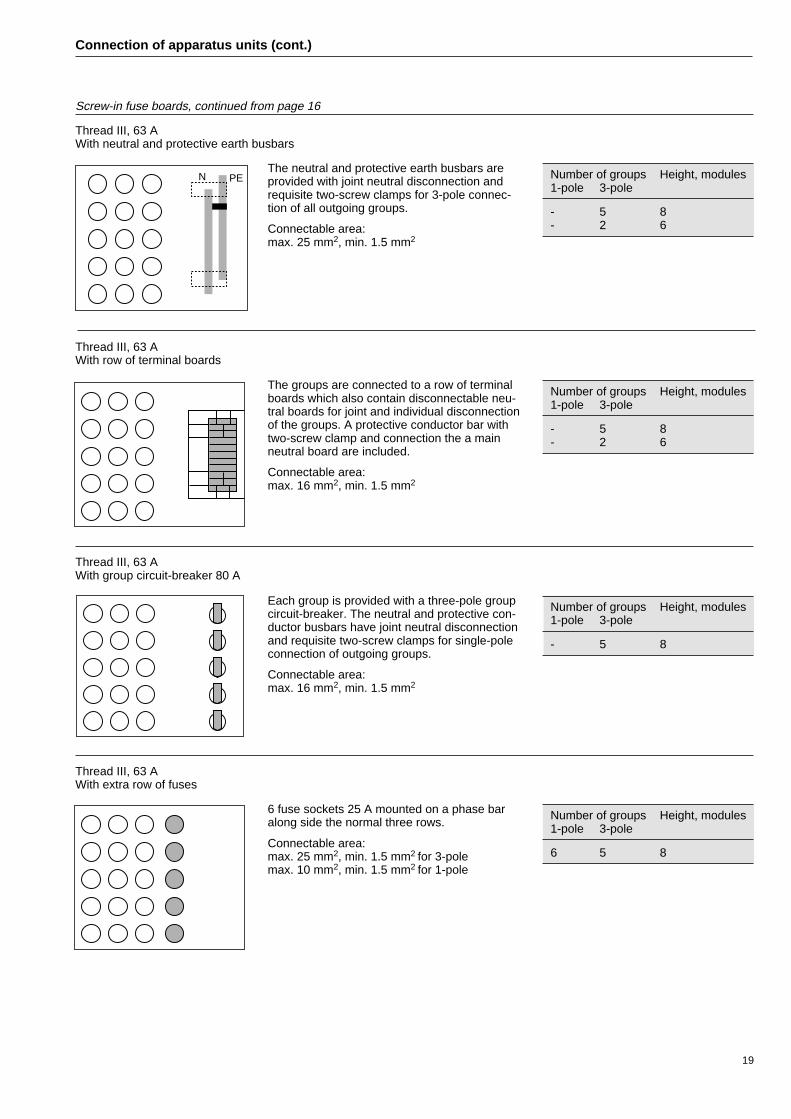
Thread III, 63 AWith neutral and protective earth busbars
Number of groups Height, modules1-pole 3-pole
- 5 8- 2 6
The neutral and protective earth busbars areprovided with joint neutral disconnection andrequisite two-screw clamps for 3-pole connec-tion of all outgoing groups.
Connectable area:max. 25 mm2, min. 1.5 mm2
Thread III, 63 AWith row of terminal boards
The groups are connected to a row of terminalboards which also contain disconnectable neu-tral boards for joint and individual disconnectionof the groups. A protective conductor bar withtwo-screw clamp and connection the a mainneutral board are included.
Connectable area:max. 16 mm2, min. 1.5 mm2
Number of groups Height, modules1-pole 3-pole
- 5 8- 2 6
Thread III, 63 AWith group circuit-breaker 80 A
Each group is provided with a three-pole groupcircuit-breaker. The neutral and protective con-ductor busbars have joint neutral disconnectionand requisite two-screw clamps for single-poleconnection of outgoing groups.
Connectable area:max. 16 mm2, min. 1.5 mm2
Thread III, 63 AWith extra row of fuses
6 fuse sockets 25 A mounted on a phase baralong side the normal three rows.
Connectable area:max. 25 mm2, min. 1.5 mm2 for 3-polemax. 10 mm2, min. 1.5 mm2 for 1-pole
Number of groups Height, modules1-pole 3-pole
6 5 8
Screw-in fuse boards, continued from page 16

20
MCB terminals
PE + N placed in 5-conductor system PEN/PE +N placed in 4-conductor system (neutral bar optional)
Internal cables from back-up circuit-breakeror from main busbarCable duct for external cable
Neutral bar
PE bar
Connection of external cables direct to terminalsof MCB apparatuses
Internal distribution busbar forMCB apparatus
Disconnector board N-PE
Connection of apparatus units (cont.)
Basic set (PEN)

21
Connection of apparatus units (cont.)
Connection unit for auxiliary circuits forwithdrawable units 2M – 20M.
For withdrawable units, operating and signal cables are connected to terminal units(sliding contact units).
Max. connectable area: 1 x 2.5 mm2 screw clamp + 2 x flat pin terminal 2.8 x 0.8.
Max. rated current/voltage: 10 A/500 V.
Connection of screened conductors is best done to an earthing bar located on theleft front post in the cable area (option).
Auxiliary circuits, removable units
For removable units, signal cables are to be connected to plug-in ten-poleconnection blocks.
Max. connectable area: 1 x 4 mm2 screw clamp.
Max. rated current/voltage: 10 A/500 V.
Protective earthingThe vertical protective earth busbar (PE) has holes 50 mm apart for cable lugconnection down to 4 mm2 conductor area. Conductors with areas of 1 – 10 mm2
are to be connected to a smaller bar mounted on the large bar.
The PE busbar is located right at the back of the cable area to the left.
Vertical protective earth busbar (PE).
Plug-in connection block for auxiliarycircuits for removable units.

22
Withdrawable apparatus units, handling
DescriptionThe withdrawable apparatus units have plug-in connection both for the incomingsupply from the vertical busbar system and for outgoing cables. The units can bepulled out without having to unscrew any bolts. Interlocking takes place via thegroup´s operating handle. The auxiliary circuits are connected via multi-pole plug-incontact units. Unoccupied apparatus seats are screened off to minimise the risk ofunintentional touching of live parts.
Withdrawable starter.
Withdrawable unit in disconnected position.
Unoccupied apparatus seat for withdrawable unit.
Compact unit with two units in operating position, one unit indisconnected position and one unoccupied apparatus seat.

23
Withdrawable apparatus units, handling (cont.)
Operation, normally wide unitThe unit has two fixed positions: connected position and disconnected position.The operating knob is used both for operating the power switch and for interlockingthe apparatus unit. The knob has four different positions.
TESTT
TEST
TEST
TEST
Knob position
On
Unit function when inconnected position
All electrical circuits connected.Cover interlocked.
Off All electrical circuits disconnected.
Test Main circuits disconnected,auxiliary circuits connected.
Move All electrical circuits disconnected.The unit can be moved.When withdrawing from the connectedposition, the unit is automatically lockedwhen it reaches the disconnected posi-tion *).For further movement outwards, theknob must be moved back to the moveposition.
*) Where the unit is in the disconnectedposition (see the figure on page 20) theposition of the knob is of no importancesince both the main and theauxiliary circuits are disconnected.
The knob can be locked using up tothree padlocks in the positions Off andTest.

24
Withdrawable apparatus units, handling (cont.)
Unit function when inthe connected position
All electrical circuits connected.The unit interlocked in the connectedposition.
All electrical circuits disconnected.The unit interlocked in the connectedposition.
Main circuits disconnected, auxiliarycircuits connected.The unit interlocked in the connectedposition.
All electrical circuits disconnected.The unit can be moved.
Operation, compact unitThe unit has three fixed positions: connected position, test position and disconnect-ed position. The operating knob is used both for operating the power switch and formechanical interlocking of the unit. A microswitch with two making and two break-ing contacts is included for electrical interlocking. The knob has five different posi-tions.
Knob position
On
OffTo turn from ”0” to ”1”,the knob must bepressed in.
Test
Move
Disconnected –
Unit function when indisconnected position
–
–
–
All electrical circuits disconnected.The unit can be moved.
All electrical circuits disconnected.The unit can be moved.When withdrawing from the connectedposition, the unit is automaticallyblocked when it reaches the discon-nected position (pulled out 30 mm fromthe run position). For further movementoutwards, the knob must be turnedback to the move position.
The knob can be locked with up tothree padlocks in the positions Offand Test.

25
Withdrawing, normally wide unitThe unit is in the run position (pushed right in).
1. Turn the knob to the Move position.
Pull (jerk) the unit out so far that it is automatically locked by the interlockingmechanism. Use the two handles. The operating knob must not be used as ahandle when moving the unit.
When moving the unit, the knob immediately moves back to the 0 positionwhen the unit starts moving. This is perfectly normal; continue moving withouttouching the knob.
2. The unit is now in the disconnected position.
3. For further movement, turn the knob to the Move position.
4. The unit is now free to be pulled out to the safety stop.
Since the weight of the unit can prove to be too heavy if the hands remain onthe handles, shift your grip when the unit is half-way out. For 2M and 4M units,grasp under the sides about half way along and pull the unit outagainst the safety stop. For 6M units and bigger, there should betwo persons pulling the unit out of the cubicle. When the unit iswithdrawn half-way, one person on each side should grasp theside of 6M units, or the handle on the sides of larger units, andpull the unit out against the safety stop. Since the unit now has itscentre of gravity outside the cubicle the unit cannot be left in thisposition. Be careful when large, heavy units are handled so as toavoid injuries to persons nearby and damage to mechanical parts.To make handling of large units easier, and also from the ventila-tion point of view, they should be placed as far down in the cubicleas possible.
5. Before removing the unit from the cubicle, release the safety stop bypressing down the catch at the bottom of the left-hand side of the ofthe unit.
The catch is so placed that the correct balance is obtained whenpulling out 2M and 4M units alone. For larger units, it is locatedso that it is easily accessible for the person standing on the left.For 2M and 4M units located at a level below chest height graspunder the sides about half way along and release the catch withyour left thumb. If they are at a higher level, grasp under the uniton the guide plate with your right hand and release the catchwith your left hand.
6. The unit is now ready to be pulled completely out of thecubicle
When using the special apparatus hoist available for ABB’s apparatus units,this instruction should be followed up to point 3, after which the instructionssupplied with the apparatus hoist should be complied with (1TSC 232-SE).
If a hoisting trolley is used for depositing the unit on, the unit can be placed onits guide plate, inserting wooden slats or similar underneath so as not to dam-age the front door and mechanism. When temporarily storing the unit on thefloor, it should be placed with its left side (seen from the front) on the floor soas not to damage the unit´s withdrawal mechanism. The floor surface shouldbe flat and smooth so as not to scratch the paintwork on the unit. For perma-nent storage on the module bottom plate, the unit should be blocked up so asnot to damage the unit´s withdrawal mechanism and the underneath of thepanel.
Withdrawable apparatus units, handling (cont.)
Withdrawing, compact unitThe unit is in the run position (pushed right in).
Turn the knob to the Move position.
The unit is now ready to be pulled out of the cubicle completely. Use the handle(the operating knob must not be used as a handle when pulling out the unit).
When moving to the disconnected position, turn the knob by hand to the discon-nected position while pulling (jerking) the unit out of the Run position. Pull outwardsuntil the unit is blocked in the disconnected position. To pull the unit out completelyfrom the disconnected position, return the knob to the Move position, whereuponthe unit is free to be pulled out.
26
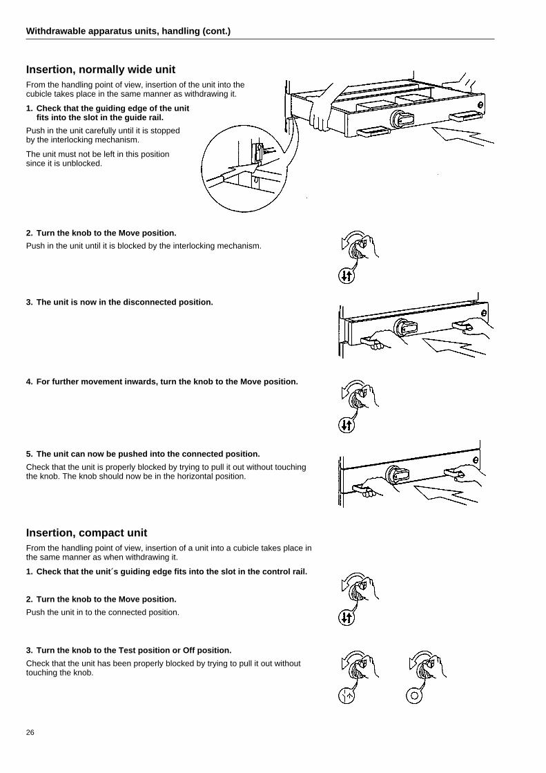
Insertion, normally wide unitFrom the handling point of view, insertion of the unit into thecubicle takes place in the same manner as withdrawing it.
1. Check that the guiding edge of the unitfits into the slot in the guide rail.
Push in the unit carefully until it is stoppedby the interlocking mechanism.
The unit must not be left in this positionsince it is unblocked.
2. Turn the knob to the Move position.
Push in the unit until it is blocked by the interlocking mechanism.
3. The unit is now in the disconnected position.
4. For further movement inwards, turn the knob to the Move position.
5. The unit can now be pushed into the connected position.
Check that the unit is properly blocked by trying to pull it out without touchingthe knob. The knob should now be in the horizontal position.
Withdrawable apparatus units, handling (cont.)
Insertion, compact unitFrom the handling point of view, insertion of a unit into a cubicle takes place inthe same manner as when withdrawing it.
1. Check that the unit´s guiding edge fits into the slot in the control rail.
2. Turn the knob to the Move position.
Push the unit in to the connected position.
3. Turn the knob to the Test position or Off position.
Check that the unit has been properly blocked by trying to pull it out withouttouching the knob.

27
Withdrawable apparatus units, handling (cont.)
ExtensionExtension of the equipment can take place with the switchgear live, but it isnaturally preferable to work with the voltage switched off.
1. Remove the panel in question as well as the panel immediately below it.
Remove the panel bar as well (only at higher degree of protection).
2. Insert and mount a new cassetteplate and guide rail.
4. Mount connection units for main andauxiliary circuits.
5. Connect up cables for mainand auxiliary circuits.
Follow instructions for connecting upapparatus units.
6. Fit the panel below the new unitback in and push the unit into place.
Follow instructions for inserting units.
Since the units are protected against adjacent units via cassette plates, and the ter-minals are provided with cable shields, no further measures need be adopted whencarrying out extensions with the equipment live.
Before energising the equipment, see the instructions under ”Concluding work” and”Check-list upon commissioning”.
In general, it is important when extending equipment that the relevant regulationsregarding measures that are to be adopted, such as marking with sign-plates, etc.,are complied with.

28
Removable apparatus units, handling
DescriptionThe removable apparatus units have plug-in connection for the incoming supplyfrom the vertical busbar system, whereas the outgoing cables are connected per-manently direct to the apparatus terminals. The units can be taken out after theoutgoing cables have been disconnected and four fixing bolts removed. The auxil-iary circuits are connected via multi-pole plug-in contact units.
Removable unit in connected position.
OperationThe operating knob has two positions.
Removable R unit.
T
Knob position
On
Unit function
All electrical circuits connected.Panel interlocked.
Off All electrical circuits disconnected.The unit can be removed afterdisconnecting cables and removingfixing bolts.
Marking label for a replaceable R unit.
Replaceability, MNS – Center 5000/1600Removable apparatus units (R units) supplied before Week 40, 1995 donot fit and should not be used in MNS cubicles. Their apparatus plates havethe wrong dimensions for MNS, leading to plug-in contacts not fitting properly.The mark of a non-replaceable R unit is that the plug-in holder consists of 3 or 4single-pole holders.
R units supplied after Week 40, 1995 can be used in both MNS andCenter 5000/1600 if proper spacing using spacer set 1TSA2 21518-A is appliedin Center 5000/1600. (Standard design for Center 5000/1600 after Week 40, 1995.)No spacing is allowed in MNS cubicles.The mark of a replaceable R unit (with the aid of spacers) is that the plug-in holderconsists of a 4-pole holder and that the apparatus plates are marked with a label.

29
Removable apparatus units, handling (cont.)
Removing a unit1. Set the knob in the 0 position (breaker off).
2. Open the panel and remove any fuses.
3. Check that there is no voltage at the apparatusterminals (that the equipment is not live).
4. Detach the main cables.
Pull out the cables through the hole in the group’s end panel.(Remove any screens and cable shields.)
Protect the cable ends against any live parts in the cablearea.
5. Disconnect any connection units for operating cables.
6. Remove the four fixing bolts.
7. The unit is now free and can be taken out.
8. Close the panel.
Mounting a unit1. Open the panel.
2. Set the handle in the 0 position (breaker off) andremove any fuses.
3. Insert the unit and bolt it fast (four fixing bolts).
3. Test that there is no voltage at the apparatus terminals(that they are not live).
4. Connect up the connection units for the operatingcables.
5. Connect the main cables, fit screens and cableshields.
6. Fit fuses, where applicable.
8. Close the panel.
30
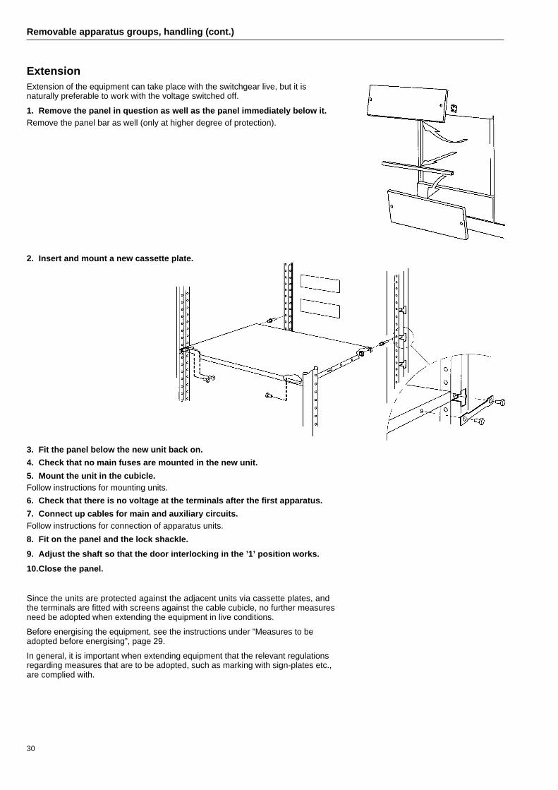
Removable apparatus groups, handling (cont.)
ExtensionExtension of the equipment can take place with the switchgear live, but it isnaturally preferable to work with the voltage switched off.
1. Remove the panel in question as well as the panel immediately below it.Remove the panel bar as well (only at higher degree of protection).
2. Insert and mount a new cassette plate.
3. Fit the panel below the new unit back on.
4. Check that no main fuses are mounted in the new unit.
5. Mount the unit in the cubicle.Follow instructions for mounting units.
6. Check that there is no voltage at the terminals after the first apparatus.
7. Connect up cables for main and auxiliary circuits.Follow instructions for connection of apparatus units.
8. Fit on the panel and the lock shackle.
9. Adjust the shaft so that the door interlocking in the ’1’ position works.
10.Close the panel.
Since the units are protected against the adjacent units via cassette plates, andthe terminals are fitted with screens against the cable cubicle, no further measuresneed be adopted when extending the equipment in live conditions.
Before energising the equipment, see the instructions under ”Measures to beadopted before energising”, page 29.
In general, it is important when extending equipment that the relevant regulationsregarding measures that are to be adopted, such as marking with sign-plates etc.,are complied with.

31
Measures to be adopted before energising
Remove wire ends and debris from cable stripping, etc.Wipe off any grease and dirt.Check that tools and assembly material have not been left in the cubicles.Vacuum-clean the cubicles.
Concluding work
Check-list uponcommissioningThere follows a list of points to beobserved when inspecting and testinga directly earthed system.In the case of indirectly earthedsystems, a check must always be madethat all metallic parts are correctlyearthed. Check the earth fault protec-tion signal as well.Apart from this check-list, local andcurrent national regulations andinstructions must be complied with.
1. ❐ Insertion of fusesInsert all necessary fuses in the mainand auxiliary circuits.
2. ❐ Checking of fusesCheck that all fuses agree with theapparatus list and the circuit diagram.
3. ❐ Setting of MCCBsSet instantaneous and thermal trippingof MCCB units, based on load andselectivity.The instantaneous protection for incom-ing circuit-breakers and large distribu-tion breakers can be temporarily set atthe lowest value to ensure the fastestpossible tripping in the event of a shortcircuit during commissioning.
4. ❐ Checking of currenttransformers
Check that the secondary winding in allcurrent transformers is connected(under load). Otherwise the secondarywindings must be short-circuited.
5. ❐ Setting of startersSet the thermal overload protection atthe rated current of the motor.
N.B. Setting above or below the scalerange is not permitted.
6. ❐ Check the main busbarsMake a visual inspection to see thatthe bolts in busbar joints between thecubicles are tight.
7. ❐ Check the PE and N barsCarry out a visual inspection to ensurethat the bolts in busbar joints betweenthe cubicles are tight.
8. ❐ Check phase sequence andmarking
9. ❐ Check internal connectionsCheck all internal connections betweenthe cubicles.
10. ❐ Carry out insulation tests10.1 Check that incoming supply is
switched off.
10.2 Check that all operatingvoltages are switched off.
10.3 Check that all relays areswitched off.
10.4 Check that all large MCCBs(incoming circuit-breakers) aredisconnected.
10.5 Check the insulation on themain busbars using a meggerwith 1 or 0.5 kV. The insulationresistance should be ≥ 1 Mohm.
Phase Insulation resistanceMohm
L1 – N
L2 – N
L3 – N
L1 – L2
L2 – L3
L3 – L1
10.6 Reconnect all relays , operatingvoltages and circuits that weredisconnected during theinsulation tests.
11. ❐ Energising the equipment11.1 Check that incoming and
outgoing circuit-breakers anddisconnectors are off.
11.2 Check that all doors and coversin the switchgear are closed.
11.3 Switch on the supply andconnect in the switchgear, ifpossible one cubicle or sectionat a time.
11.4 Check the phase sequence of aunit. It is enough to check oneunit since the phase sequencehas already been checked(point 8).
11.5 Check the units one at a timeby:
- switching on the circuit-breaker
- checking the main circuit tothe connected load
- checking that all importantinterlocking measures agreewith the circuit diagram.
12. ❐ Final inspection12.1 Check that all voltmeters,
ammeters and wattmeters arein working order.
12.2 Check that all instantaneousprotections that have beenturned down duringcommissioning work are resetto their operating positions.
12.3 Check that no vibrations ornoises occur in the busbarsystems.
Warning - high currentsA short-circuit current in low-voltage switchgear is normally very high. Depending on the set tripping time, selectivity,etc., high short-circuit currents with relatively long duration can occur.A short circuit can cause serious injuries to personnel and damage to material. It is therefore essential to use properlyinsulated tools and secured instruments in commissioning work.

ABB Installation ABLow Voltage Systems DivisionS-721 62 Västerås, SwedenTelefon: +46 21 34 60 00Telefax: +46 21 34 61 10
1TS
C 2
34-E
N
974
14 R
ekla
mC
ente
r V
äste
rås
1997
11/
Doc
uTec
h 40
0ex