mobile vision screener - plusoptix · pdf file · 2018-02-16mobile vision screener...
TRANSCRIPT

Page 1/61
Mobile Vision Screener
“plusoptiX S12C” “plusoptiX S12R”
User Manual
Edition: 02/06/2018 - CAD
Plusoptix GmbH Neumeyerstrasse 48
90411 Nuremberg Germany
www.plusoptix.com
Englisch

Page 2/61
Please read this user manual before using the “plusoptiX S12” for the first time! It explains how the device functions. When the “plusoptiX S12” is switched on, additional training videos can be accessed by touching the blue “?”.
Table of Contents
1 Intended use and responsibility of the operator ......................................................... 4 2 Commissioning the “plusoptiX S12” .......................................................................... 7 2.1 Checking the scope of delivery .................................................................................7 2.2 Learning about the “plusoptiX S12” ..........................................................................8 2.3 Inserting and charging the rechargeable batteries .................................................. 10 2.4 Switching the “plusoptiX S12” on and off ................................................................ 11 2.5 Screen displays and training videos ....................................................................... 12 3 Performing measurements ...................................................................................... 13 3.1 Taking the surroundings into consideration ............................................................ 13 3.2 Preparing for a measurement ................................................................................. 14 3.3 Starting the measurement and adjusting the “plusoptiX S12” ................................. 15 3.4 Viewing the measurement results ........................................................................... 18 3.5 Performing the next measurement ......................................................................... 22 4 Documenting measurement results ........................................................................ 23 4.1 Printing self-adhesive label with “plusoptiX P12” (optional accessory) ................... 23 4.2 Saving screening reports to a SD card ................................................................... 24 4.3 Entering or retrieving patient data on the “plusoptiX S12” (nur plusoptiX S12C) ..... 26 4.3.1 Entering or retrieving patient data before the measurement ....................................26 4.3.2 Entering or retrieving patient data after the measurement .......................................29 4.3.3 Importing patients from the EMR software before the measurement (CSV) ............32 4.3.4 Importing patient data via the USB interface ...........................................................32 4.4 Exporting data (only plusoptiX S12C) ..................................................................... 34 4.5 Deleting entries from the database (only plusoptiX S12C) ...................................... 35 5 Practical Tips .......................................................................................................... 36 5.1 Adjust the settings .................................................................................................. 36 5.2 Adjust the basic settings ......................................................................................... 37 5.3 Selecting the referral criteria ................................................................................... 38 5.4 Setting up the screen lock (only plusoptiX S12C) ................................................... 38 5.5 Setting up the network access WLAN (only plusoptiX S12C) ................................. 39 5.6 Mini-USB interface ................................................................................................. 42 5.7 Downloading software updates .............................................................................. 42 5.8 Connecting the USB keyboard and mouse (optional) ............................................. 46 6 Troubleshooting guide ............................................................................................ 47 6.1 Trouble-shooting when switching device on ........................................................... 47 6.2 Malfunctions when using touch screen ................................................................... 48 6.3 Troubleshooting measuring interruptions ................................................................ 49 7 Maintenance, calibration, service and guarantee .................................................... 56 8 Technical details about the “plusoptiX S12” ............................................................ 57

Page 3/61
List of figures
Figure 1: Device in cardboard box (plusoptiX S12C) ............................................................. 7 Figure 2: Front view of the device (plusoptiX S12C) .............................................................. 8 Figure 3: Rear view of the device (plusoptiX S12C) .............................................................. 9 Figure 4: Battery compartment view of the device (plusoptiX S12C).....................................10 Figure 5: Switching between the screen and training videos ................................................12 Figure 6: Measuring environment .........................................................................................13 Figure 7: Aligning the device ................................................................................................15 Figure 8: Detecting the correct measuring distance ..............................................................16 Figure 9: Self-adhesive label (74 mm x 49 mm) ...................................................................23 Figure 10: Example of a screening report (DinA4) ................................................................24 Figure 11: Sample of a CSV table ........................................................................................32 Figure 12: Downloading the software update via WLAN .......................................................44 Figure 13 : Software Update via Mini-USB-cable ..................................................................45 Figure 14: Type plate with serial number ..............................................................................56
List of screenshots
Screenshot 1: Setting the date and time ...............................................................................11 Screenshot 2: Home page ....................................................................................................14 Screenshot 3: Selection of the age group .............................................................................14 Screenshot 4: Overview of the results pages ........................................................................18 Screenshot 5: “Camera image” results page ........................................................................19 Screenshot 6: Viewing the measurement values ..................................................................20 Screenshot 7: “Database” results page ................................................................................21 Screenshot 8: Entering patient data......................................................................................26 Screenshot 9: Allocating entered patient data ......................................................................27 Screenshot 10: Missing patient data .....................................................................................27 Screenshot 11: Shortlist with entries with identical character strings ....................................28 Screenshot 12: Patient data overview ..................................................................................28 Screenshot 13: Entering patient data ....................................................................................29 Screenshot 14: Allocating entered patient data ....................................................................29 Screenshot 15: Missing patient data .....................................................................................30 Screenshot 16: Shortlist with entries with identical character strings ....................................30 Screenshot 17: New entry on the “database” results page ...................................................31 Screenshot 18: Data export ..................................................................................................34 Screenshot 19: Deleting entries from the database ..............................................................35 Screenshot 20: Deleting patients from the database ............................................................35 Screenshot 21: Settings .......................................................................................................36 Screenshot 22: Adjust the basic settings ..............................................................................37 Screenshot 23: Selecting the referral criteria ........................................................................38 Screenshot 24: Setting up the screen lock............................................................................38 Screenshot 25: Activating WLAN ..........................................................................................39 Screenshot 26: List of active WLAN connections..................................................................40 Screenshot 27: Entering a password for a WLAN connection ...............................................40 Screenshot 28: Viewing active network connection ..............................................................41 Screenshot 29: Downloading software updates ....................................................................43 Screenshot 30: “Measurement values” results page after an inconclusive measurement .....49

Page 4/61
1 Intended use and responsibility of the operator
Please follow the instructions in this user manual. This will help you to avoid risks and to obtain accurate measurement results. The symbols in this user manual have the following meanings:
Please read this user manual before using the “plusoptiX S12” for the first time! It explains the device’s functions. When the “plusoptiX S12” is switched on, additional training videos can be accessed by touching the blue “?”.
Warnings and tips are labelled with the Attention! symbol.
The “plusoptiX S12” fulfils the requirements of Medical Devices Directive 2007/47/EEC.
The “plusoptiX S12” fulfils the requirements for a Type B applied part of EN 60601-1.
Only connect the “plusoptiX S12” to the enclosed GSM36P12-P1J medical power supply.
The “plusoptiX S12” can be stored and transported at a temperature between 0°C and +50°C (i.e. 32°F to 122°F). A temperature between +10°C and +50°C (i.e. 50°F to 122°F) with a non-condensing air humidity of 20% to 80% is required to operate the device.
Disposal
Do not dispose of the “plusoptiX S12” as domestic waste. Please send the “plusoptiX S12” to Plusoptix (Plusoptix GmbH, Neumeyerstrasse 46, 90411 Nuremberg, Deutschland) for environmentally friendly recycling. Plusoptix will reimburse you for the cost of the return.
0°C
+50°C
12V

Page 5/61
Intended use
The “plusoptiX S12” is used for the early detection of visual disorders (preventative eye care). These visual disorders can cause permanent loss of vision in an eye (amblyopia) if they are not discovered and treated in the early years. To detect visual disorders, the “plusoptiX S12” measures the sphere, cylinder, axis, line of vision and pupil size of both eyes at the same time. Using these measurement values, the spherical equivalent, gaze symmetry and interpupillary distance are calculated. All measurement values are compared with age-dependent referral criteria. “Refer” is automatically displayed as a precautionary result for every patient requiring an ophthalmologist appointment.
Note: Preventative eye care with the “plusoptiX S12” does not replace the eye examination carried out by an ophthalmologist. An ophthalmologist remains the only one who can interpret the measurement values and establish a diagnosis. The measurement values must not be used directly to prescribe glasses or contact lenses.
All children who are not already being treated by an ophthalmologist should undergo a preventative eye care examination. The first preventative eye care examination should be carried out at the age of one. They should then be repeated regularly, as the eyes can change during growth and new visual disorders can appear at any time. All children with a “Refer” result from the preventative eye care examination should be referred for an eye examination with an ophthalmologist.
Note: False-positive and false-negative results can occur in any type of preventative examination.

Page 6/61
Responsibility of the operator - The operator is responsible for ensuring that only trained users handle the
“plusoptiX S12”.
- Training must at least include reading the user manual and a briefing about the operation of the “plusoptiX S12”. The briefing about the operation of the “plusoptiX S12” can be carried out by a previously trained user. In addition to this, briefings are also provided by Plusoptix and by Plusoptix dealers authorised by Plusoptix.
- The operator is responsible for ensuring that external devices that are connected to the “plusoptiX S12” meet the standards of EN 60601-1 and EN 60601-1-1 when attached to the “plusoptiX S12”.
- The operator is informed that opening the “plusoptiX S12” runs the risk of receiving an (invisible) electric shock. The “plusoptiX S12” loses its approval as a medical product when it is opened. The operator is responsible for ensuring that the “plusoptiX S12” is only opened by Plusoptix or a dealer authorised by Plusoptix for service or warranty cases.
Warning: Use of accessories, transducers and cables other than those specified or provided by the manufacturer of this equipment could result in increased electromagnetic emissions or decreased electromagnetic immunity of this equipment and result in improper operation.
Warning: Use of this equipment adjacent to or stacked with other equipment should be avoided because it could result in improper operation. If such use is necessary, this equipment and the other equipment should be observed to verify that they are operating normally

Page 7/61
2 Commissioning the “plusoptiX S12”
Thank you for choosing to purchase the “plusoptiX S12”! Plusoptix is the global leader in the development, production and distribution of medical devices for pediatric ophthalmic examination. If you have any further questions after reading this user manual, please do not hesitate to contact us.
2.1 Checking the scope of delivery The device is supplied in a cardboard box with foam padding that protects the device from damage. If the device packaging shows signs of damage at the time of delivery, please inform the seller of the device immediately.
Figure 1: Device in cardboard box (plusoptiX S12C) Please check that the contents of the packaging are complete at time of delivery. The scope of delivery includes: - User Manual for plusoptiX S12 - Mobile Binocular Autorefractor "plusoptiX S12C" or "plusoptiX S12R" - Medical power adapter GSM36P12-P1J - 110V/230V power cord (in compartment under the "plusoptiX S12C" or "plusoptiX S12R") - 6 x rechargeable AA batteries - SD card (inserted into device) Optional accessories: - +3,00dpt. lenses for accommodation test - Carrying case for plusoptiX S12 - Wireless label printer “plusoptiX P12” for plusoptiX S12
If the delivery is incomplete, please inform the seller of the device immediately.
6 x rechargeable AA batteries
110V/230V power cord
Medical power adapter
plusoptiX S12C or
plusoptiX S12R
SD card

Page 8/61
2.2 Learning about the “plusoptiX S12”
The “plusoptiX S12” is made up of the device with a child-friendly smiley face.
During a measurement, the “plusoptiX S12” records a series of images. To ensure children look into the camera during the measurement, the “plusoptiX S12” plays a warble sound.
The speaker, the camera lens and the LEDS needed to light the images are located behind the black protective screen with the smiley. This smiley helps to keep the child’s attention.
Attention: If a child is not looking at the camera lens in the middle behind the hexagon during the measurement, this can lead to a cancellation of the measurement or incorrect measured values of the visual symmetry. Therefore do not use any other external fixation aids! Attention: If you need to put the device on its rear side, e.g. to insert or replace the rechargeable batteries, please place a soft cloth under the device. Note: To prevent the protective shield from becoming dirty, we recommend that you do not touch it. If the protective shield does become dirty, read chapter 7 "Maintenance, calibration, service and guarantee" for cleaning instructions.
Speaker
Protective shield with face
mmmmmm
Camera lens behind hexagonal
nose
Figure 2: Front view of the device (plusoptiX S12C)

Page 9/61
plusoptiX S12C has a 5.7 inch screen with capacitive touch sensor located on the rear side of the device. To activate one of the functions displayed on the screen, all you need to do is gently touch the screen. The screen and touch sensor are protected from damage behind a thin glass shield. plusoptiX S12R has a 4.3 inch screen with resistive touch sensor located on the rear side of the device. To call up a function displayed on the monitor screen, it is sufficient to tap the screen with the tip of your finger or with your finger nail. Screen and touch sensor are protected behind a thin transparent plastic cover. Two orange buttons are visible – the On/Off button, and the Shutter. Chapters 2.4 "Switching the “plusoptiX S12” on and off" and 3.3 "Starting the measurement and adjusting the “plusoptiX S12”" deal with the functions of these buttons. Integrated interfaces
The cradle has 4 connections:
- 12V connection for the medical power supply - SD card - USB - Mini-USB to download a software Update (see chapter 5.6)
The USB interface can be used as follows:
- To import an infographic (see Chapter 4.2) - To import patient data (see Chapter 4.3.4 – only plusoptiX S12C) - To export data (see Chapter 4.4 – only plusoptiX S12C) - Optional connection of a USB keyboard and USB mouse (see Chapter 5.8)
Note: All interfaces are mounted upside down. This means that all media (i.e. USB flash drives, Mini-USB plugs and SD cards) must be connected with the upper side facing down.
Screen
Shutter
On/Off button
Mini USB
SD card
12V input
USB
Figure 3: Rear view of the device (plusoptiX S12C)

Page 10/61
2.3 Inserting and charging the rechargeable batteries
Figure 4: Battery compartment view of the device (plusoptiX S12C)
Attention: If you need to put the device on its rear side, e.g. to insert or replace the rechargeable batteries, please place a soft cloth under the device.
To insert the batteries, please put the device on a level working surface on its rear side.
Attention: If you insert batteries other than those supplied, you should exclusively use rechargeable Nickel Metal Hydride NiMH/AA HR6 batteries with a capacity of at least 1900 mAh and a quick-charge rate of min. 1 A.
Now remove the battery compartment cover using a 1-cent coin, and insert the supplied rechargeable batteries.
Note: When inserting rechargeable batteries, please ensure that the contacts are located on the correct side.
Note: The type plate with the serial number (S/N 120xS-xxx-xxxx xxxx) is located under the battery compartment. If you contact us regarding extended service or warranty questions, please remember to always quote the serial number of your device. The S/N number helps us to answer your question quickly.
Type plate
Battery compartment

Page 11/61
After inserting the rechargeable batteries, close the battery compartment cover and place the device in front of you. Now connect the medical power adapter with its power cable to the wall socket and check whether voltage is present (green light diode at the top of the medical power adapter lights up). Then connect the 12V charging cable of the medical power adapter to the device. The inserted rechargeable batteries will now be charged automatically. The charging time of the batteries depends on the charge level of the batteries. The maximum battery charging time is 3 hours for the supplied rechargeable batteries.
2.4 Switching the “plusoptiX S12” on and off
Press the On / Off button briefly to turn the device on. The screen will come on immediately and the “plusoptiX S12” will start up. After approx. 25 seconds, the “plusoptiX S12” is ready to operate. After inserting the batteries, the date and time settings page is displayed on the screen.
The selected time and date format is highlighted (1). Using the orange arrows (2), set the right date and current time. Confirm your entries with the green checkmark (3). The date, time and display format can be changed at a later date in the settings (4) (see Chapter 0 “Adjust the settings”). Press the On / Off button briefly to turn the device off. The “plusoptiX S12” will turn off.
1) 2) 3) 4)
Screenshot 1: Setting the date and time
Time format buttons
Date format buttons
Setting the date button
Setting the time button

Page 12/61
2.5 Screen displays and training videos
All the screen displays of the “plusoptiX S12” are the same. The header is above, the information part in the middle and the navigation bar below. You can see the overview of available training videos by touching the blue “?” (1) button. The red “X” (2) will bring you back to the previous page.
Note: Watching training videos does not replace the need to read the user manual. They serve only to aid visualisation of what is written in the user manual.
The header shows the status. This includes, among other things:
- Date and time on the left side - Battery status at the right
The navigation bar operates the device. Among other things, you can select:
- the gear wheel (3) to access the settings - the magnifier (4) to call up the database (only plusoptiX S12C) - the “GO” button (5) to start a measurement
(If the “GO” button is flashing, a measurement can be started by touching it) - the blue “?” (1) to access the available training videos - the red “X” (2) which interrupts without saving and returns you to the previous page.
1) 2) 3) 4) 5)
Information part
Navigation bar
Training videos (
Header
Figure 5: Switching between the screen and training videos

Page 13/61
3 Performing measurements
The “plusoptiX S12” measures both eyes at the same time (binocular) in 0.5 seconds from a distance of one meter. This means that even infants with a short attention span can be measured from the age of 6 months. The simultaneous measurement of both eyes also facilitates a reliable comparison of both eyes’ measurement values.
3.1 Taking the surroundings into consideration
The measurement is carried out using infrared light, which is also contained in sunlight and in the light of bulbs and halogen spotlights, for example. This infrared light is invisible to the human eye and completely safe.
To obtain correct measurement values, it is important to avoid disruptive sources of infrared light in the examination room. Close curtains, roller blinds and shutters to block out the sun’s rays.
Turn off all light sources that produce heat. This does not mean that the examination room should be dark. Cold light sources, such as energy saving bulbs and neon lights, do not affect the measurement values.
The child must look at the “plusoptiX S12” in order for a measurement to be taken. Make sure that the child is sitting straight and their head is not turned over their shoulder. The child’s knees and nose should be facing the camera.
The attention of infants is steered towards the “plusoptiX S12” by playing a special warble sound. However, this only works if the child is not distracted by other people or objects in the examination room. Close the door of the examination room and avoid any attention-grabbing activities, such as walking around and clicking your fingers. Do not use any additional fixation aids!
1 meter measuring distance
At eye level See chapter 4.2
No direct sunlight See chapter 3.5
Pupil diameter Minimum 4 mm Maximum 8 mm
Figure 6: Measuring environment

Page 14/61
3.2 Preparing for a measurement
After you have set the time and date, the home page will be displayed every time you turn the “plusoptiX S12” on again.
Screenshot 2: Home page
Select an age group by touching the appropriate age range (see Screenshot 3). You must select the age group (1) in order to ensure the measurement values of the patient are compared with the correct age-specific referral criteria (see Chapter 5.3 “Selecting the referral criteria“).
Screenshot 3: Selection of the age group
A measurement can be performed anonymously or by indicating patient data. If no patient data is entered or no saved patient data is selected, the measurement is performed under an anonymous consecutive patient ID. The patient ID has the following structure: <last 4 digits of the serial number>-<consecutive number>-<date>-<time>
The attention span of infants is very short. You can use the fact that the examination room is unfamiliar to the infant to your advantage. An attention-grabbing warble sound in this unfamiliar environment will always arouse interest. Avoid any lengthy conversations with the parents before the measurement.
- Note:
The “plusoptiX S12R” has no internal patient database. After the measurement a single line to enter patient data will be portrayed, where you can fill in individual patient data. These data will also be portrayed in the screening report and on the self-adhesive label.
1) 2)
Page 15/61
You have the following options for entering the patient data: - Entering or retrieving patient data before the measurement (Chapter 4.3.1)
- Entering or retrieving patient data after the measurement (Chapter 4.3.2)
- Importing patients from the EMR software before the measurement (Chapter 4.3.3)
3.3 Starting the measurement and adjusting the “plusoptiX S12”
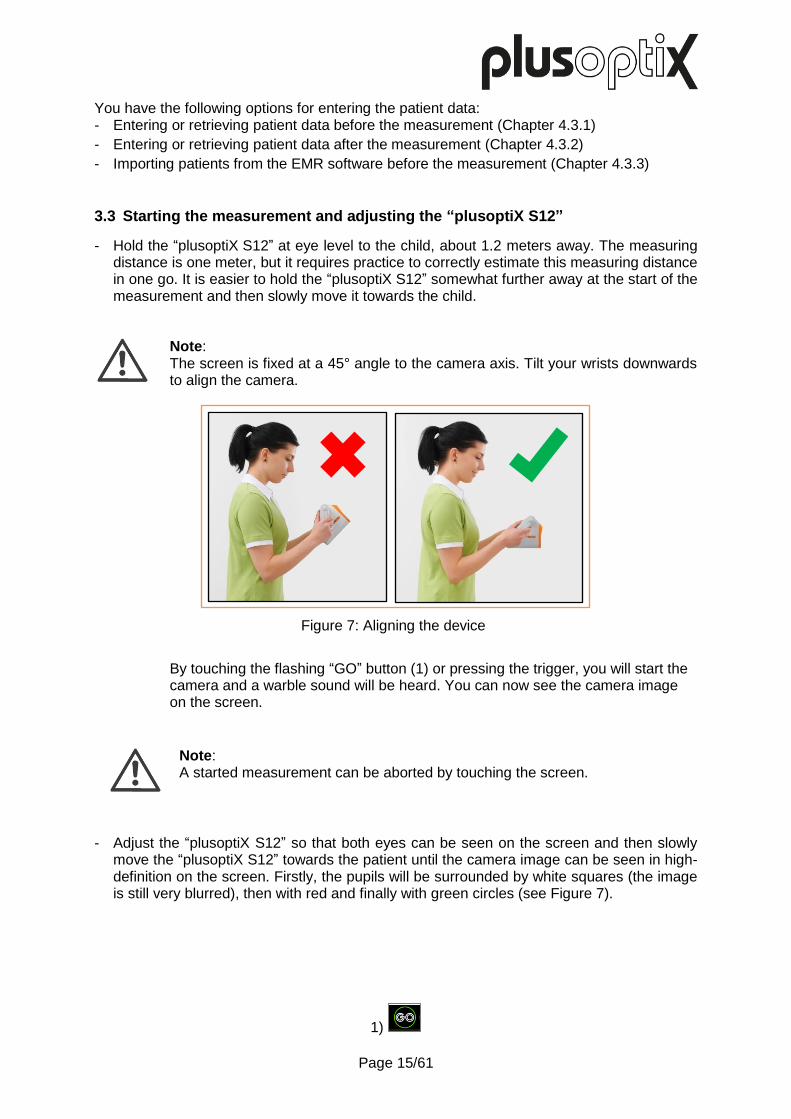
- Hold the “plusoptiX S12” at eye level to the child, about 1.2 meters away. The measuring distance is one meter, but it requires practice to correctly estimate this measuring distance in one go. It is easier to hold the “plusoptiX S12” somewhat further away at the start of the measurement and then slowly move it towards the child.
Note: The screen is fixed at a 45° angle to the camera axis. Tilt your wrists downwards to align the camera.
By touching the flashing “GO” button (1) or pressing the trigger, you will start the camera and a warble sound will be heard. You can now see the camera image on the screen.
Note: A started measurement can be aborted by touching the screen.
- Adjust the “plusoptiX S12” so that both eyes can be seen on the screen and then slowly move the “plusoptiX S12” towards the patient until the camera image can be seen in high-definition on the screen. Firstly, the pupils will be surrounded by white squares (the image is still very blurred), then with red and finally with green circles (see Figure 7).
1)
Figure 7: Aligning the device

Page 16/61
The image is blurry and two red bars will be displayed next to the camera image. As the measuring distance is too great, you can see the head of the patient virtually in its entirety. Move the “plusoptiX S12” towards the patient until the camera image can be seen in high-definition on the screen and both pupils are encircled in green.
The image is blurry and two red bars will be displayed next to the camera image. As the measuring distance is too small, the eyes can be seen on the screen. Move the “plusoptiX S12” away from the patient until the camera image can be seen in high-definition on the screen and both pupils are encircled in green.
The image can be seen in high-definition on the screen, the bars are green and both pupils are encircled in green. As soon as both pupils are surrounded by a green circle, the line between the pupils turns green and another warble sound can be heard. The “plusoptiX S12” is now a metre away from the child and the measurement begins automatically. A “ping” sound signalises the end of the measurement.
If you do not obtain any measurement values, check whether the following measuring criteria have been fulfilled:
a) The measuring distance is correct: The measuring distance must be between 95 cm and 105 cm. Check whether the camera image on the screen is in focus. You must be able to see the individual hairs on the eyelids or the eyelashes clearly on the camera image.
Note: If the screen flickers, please read Chapter 6.2 c) Screen flickers during a measurement.
Figure 8: Detecting the correct measuring distance

Page 17/61
b) The patient is looking at the camera lens: The “plusoptiX S12” and the eyes of the patient must be aligned with one another. The patient must look at the nose of the smiley face. For this reason, avoid using any additional fixation aids. Check whether the “gaze maps” on the left and right edges of the screen of the “Measurement values” results page show green dots (see Chapter 3.4).
c) Both of the patient’s pupils should be completely visible: The pupils must not be covered by eyelids, eyelashes or hair, for example. Check whether both pupils can be seen completely on the screen and whether they are encircled in green.
d) The pupil sizes are between 4 and 8 mm: Both pupil diameters must be between 4 and 8 mm.
Note: If a child is not looking at the nose of the smiley face during the measurements, this can cause a termination of the measurement or inaccurate measurement values of the gaze symmetry. For this reason, do not use any other external fixation aids!
Note: If a red error message is displayed, please read Chapter 6.3 “Troubleshooting measuring interruptions“.

Page 18/61
3.4 Viewing the measurement results As space on the screen is limited, the measurement results are spread across a total of two (plusoptiX S12R), or three screens (plusoptiX S12C) respectively. After the measurement, you will first see the “measurement values” results page. By touching the appropriate button in the middle of the navigation bar, you can access each of the three results pages.
If an anonymous measurement has been taken, a consecutive number will be displayed in
the header. Touch the button with the printer (1) to document the measurement results (see
Chapter 4 “Documenting measurement results”).
If the patient data was entered, retrieved or imported from the EMR software before the measurement, the measurement values are saved automatically. If you see the status message “Try again”, the screening report must be saved manually. After viewing the measurement results, you can return to the home page by touching the red
“X” (2) and continue with the operation. You can find more information about this in Chapter
3.5 “Performing the next measurement“.
Attention: Following an anonymous measurement, a screening report is not saved automatically. As soon as you return to the home page without previously saving, the screening report can no longer be saved and printed. The measurement values, on the other hand, are saved under a consecutive number when you take an anonymous measurement. This is shown in the header. If you take a note of this consecutive number, you can access the measurement values in the database at a later point in time and print the label.
1) 2)
Results page “camera image” Results page
“measurement values” Results page “database” (only plusoptiX S12C)
Screenshot 4: Overview of the results pages

Page 19/61
“Camera image” results page
Checking the last camera image means you can detect media opacities, which do not lead to a measurement interruption.
In addition to the measurement values, a screening result is displayed:
The measurement has been successfully completed and the “Refer”
or “Pass” screening result is displayed.
The measurement has been interrupted inconclusively and a “Try
again” or “Refer or Try again” status is displayed.
Attention: If you receive the “Refer or Try again” screening result three times in a row and the surrounding conditions for the measurement are correct, the child must be referred for a further examination by an ophthalmologist.
If applicable, a red error message is also displayed:
If a red error message is displayed above the screening result, please read Chapter 6.3 “Troubleshooting measuring interruptions“.
Note: After every measurement, check on the “Camera image” results page whether both pupils are the same lightness and whether structures can be seen within the pupils. If differences in lightness or structures can be seen, the eye must undergo a more in-depth examination.
Screenshot 5: “Camera image” results page
Screening result
Page 20/61
“Measurement values” results page
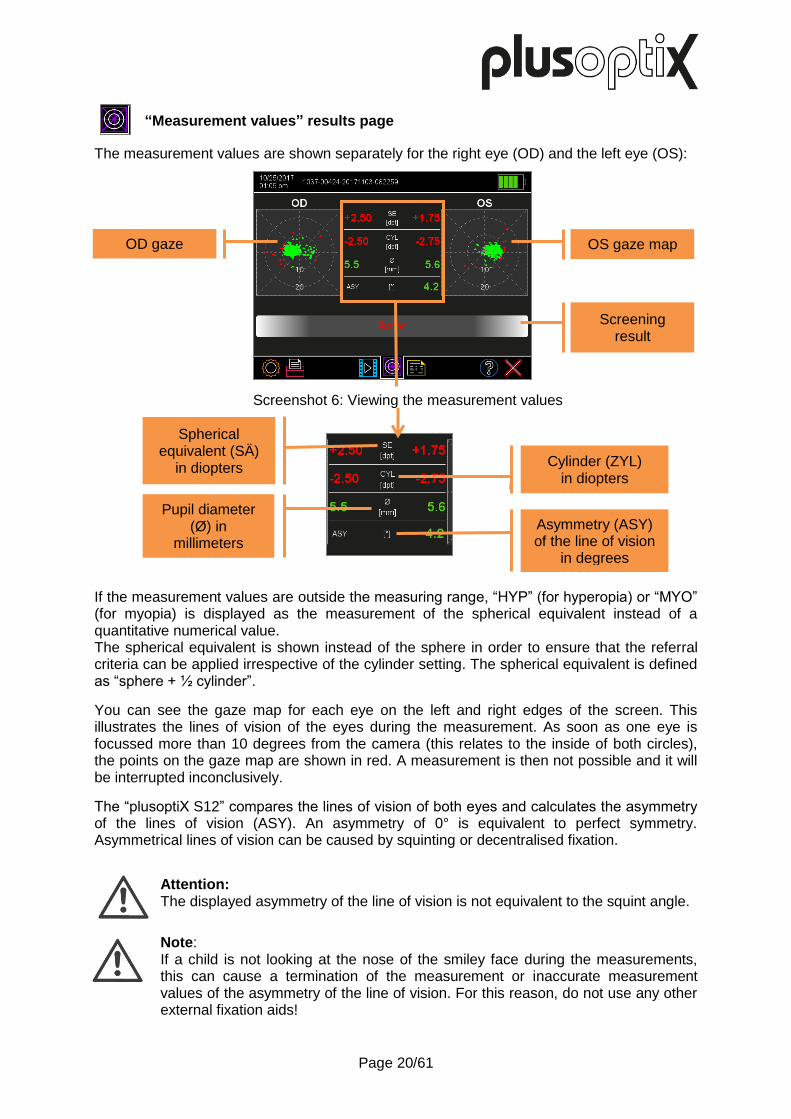
The measurement values are shown separately for the right eye (OD) and the left eye (OS):
If the measurement values are outside the measuring range, “HYP” (for hyperopia) or “MYO” (for myopia) is displayed as the measurement of the spherical equivalent instead of a quantitative numerical value. The spherical equivalent is shown instead of the sphere in order to ensure that the referral criteria can be applied irrespective of the cylinder setting. The spherical equivalent is defined as “sphere + ½ cylinder”.
You can see the gaze map for each eye on the left and right edges of the screen. This illustrates the lines of vision of the eyes during the measurement. As soon as one eye is focussed more than 10 degrees from the camera (this relates to the inside of both circles), the points on the gaze map are shown in red. A measurement is then not possible and it will be interrupted inconclusively.
The “plusoptiX S12” compares the lines of vision of both eyes and calculates the asymmetry of the lines of vision (ASY). An asymmetry of 0° is equivalent to perfect symmetry. Asymmetrical lines of vision can be caused by squinting or decentralised fixation.
Attention: The displayed asymmetry of the line of vision is not equivalent to the squint angle.
Note: If a child is not looking at the nose of the smiley face during the measurements, this can cause a termination of the measurement or inaccurate measurement values of the asymmetry of the line of vision. For this reason, do not use any other external fixation aids!
Screenshot 6: Viewing the measurement values
OS gaze map
Screening result
OD gaze plusoptiX S12
Spherical equivalent (SÄ)
in diopters
Asymmetry (ASY) of the line of vision
in degrees
Cylinder (ZYL) in diopters
Pupil diameter (Ø) in
millimeters

Page 21/61
“Database” results page (only plusoptiX S12C)
Every successful measurement is automatically documented in the database in chronological
order. Green entries indicate successful measurement results. Inconclusive measurements
are not saved.
After a measurement, the measurement values can be saved as a screening report and
printed as a label. Touch the printer (1) button in the navigation bar of a results page to send
the print job via the infrared interface and save a screening report on the SD card. For more
information about the documentation of measurement results, please see Chapter 4
“Documenting measurement results“.
Attention: All print jobs in print spooler are deleted once device is switched off or switches off for power saving automatically. Screening reports saved to a SD-card are not deleted when device is switched off or switches off for power saving.
1)
Screenshot 7: “Database” results page
Documenting the measurement results

Page 22/61
3.5 Performing the next measurement
Attention: Following an anonymous measurement, a screening report is not saved automatically. As soon as you return to the home page without previously saving, the screening report can no longer be saved and / or printed. The measurement values, on the other hand, are saved under a consecutive number when you take an anonymous measurement. This is shown in the header. If you take a note of this consecutive number, you can access the measurement values in the database at a later point in time and print the label.
After a successful measurement (“Refer” / “Pass”), you can:
Return to the home page by pressing the trigger. Previously entered or selected patient data is discarded.
Return to the home page by touching the red “X” button”. Previously entered or selected patient data is discarded.
After an inconclusive measurement (“Refer or Try again” / “Try again”), you can:
Measure the same patient again in the pre-selected age group by pressing the GO button or the trigger.
Return to the home page by touching the red “X” button”. Previously entered or selected patient data is discarded.
Attention: If you receive the “Refer or Try again” screening result three times in a row and the surrounding conditions for the measurement are correct, the child must be referred for a further examination by an ophthalmologist.
Attention: If the patient data was entered, retrieved or imported from the EMR software before the measurement, the measurement values are saved automatically. If you see the status message “Try again”, the screening report must be saved manually.

Page 23/61
First name Last name *12/31/2013 OD Refer OS -1,50 dpt Sphere -3,25 dpt -1,50 dpt Cylinder -2,25 dpt 176° Axis 4° 6,6 mm Ø Pupil 6,8 mm Pupil distance 56 mm Gaze asymmetry 1,5 ° ROC 1, Ver. 7.0.4.0 02/06/2018
www.plusoptix.com
4 Documenting measurement results
To document the measurement results, a self-adhesive label can be printed and / or a screening report can be saved to a SD card.
Touch the printer (1) button in the navigation bar of a results page to do this. In the “plusoptiX S12C” model, the patient data input screen is then displayed. Enter the patient data (see Chapter 4.3 “Entering or retrieving patient data on the “plusoptiX S12””), which should be displayed on the label or screening report and then touch the green checkmark (2) to confirm.
Note: The “plusoptiX S12R” model does not have an internal patient database. Touching the printer button after the measurement will display a single line to enter individual patient data. This data will be portrayed on the screening report and on the self-adhesive label.
If the measurement results are to be documented anonymously, touch the checkmark (2) in the navigation bar as well. This will allow you to skip the patient data entry screen. The “plusoptiX S12” saves the measurement under a consecutive patient ID. This is composed as follows:
<last 4 digits of the serial number-<consecutive number>-<date>-<time> In both cases, a print job is sent via the infrared interface after confirming the entry and the screening report is saved to an inserted SD card at the same time.
Attention: All print jobs in print spooler are deleted once device is switched off or switches off for power saving automatically. Screening reports saved to a SD-card are not deleted when device is switched off or switches off for power saving.
4.1 Printing self-adhesive label with “plusoptiX P12” (optional accessory)
The “plusoptiX P12” prints self-adhesive labels on heat-sensitive paper (i.e. no printer cartridges are required). It is battery-operated and has an infrared interface.
Note: You can find information about operating the “plusoptiX P12” in its user manual. This can be downloaded from our homepage (www.plusoptix.com).
1) 2)
Figure 9: Self-adhesive label (74 mm x 49 mm)
OD measurements
Name or ID
Date of measurement
OS measurements
Date of birth
Referral criteria and software
version

Page 24/61
4.2 Saving screening reports to a SD card The screening report is used to document the measurement values and the last camera image. For an anonymous measurement, the screening report is only saved to the SD card after confirming the patient data. If the patient data has already been entered or retrieved before the measurement in the “plusoptiX S12C” model, the screening report is automatically saved to a SD card as a PDF file at the end of every successful measurement. If you see the status message “Try again”, the screening report must be saved manually. To be able to allocate these screening reports to individual patients, the entered patient information can be found in the file names. If a patient ID has been entered in the “plusoptiX S12” instead of or as well as the patient name, this patient ID will be visible in the file name instead of the patient name. In addition to the entered data, a date and time stamp and the measurement result are added: PDF file name: Last name_FirstName-YYYYMMDD-HHMMSS.pdf
Patient information
info.png 2200 x 570 pixels
Figure 10: Example of a screening report (DinA4)

Page 25/61
An infographics is found on the lower edge of the screening report. You can design this as you wish. Create your graphic in png format with a size of 2200 x 570 pixels (w x h) and call your graphic “info.png”. Copy your graphic into the main directory of a SD card. As soon as you connect the SD card to the operational “plusoptiX S12”, your graphic will be uploaded automatically. You can find a sample graphic with the correct measurements for the information column in the download area on our homepage (www.plusoptix.com).
To print the screening report on your network or workplace printer, you must open the PDF file of the screening report from your workplace computer. There are three different access options available to do this:
Attention: The screening report is not stored in the internal patient database, but on the connected SD card. It will not be possible to retrieve screening reports in the internal patient database at a later stage. If the device has been connected to your EMR software via the device’s CSV interface, it will be sent automatically to your EMR software if this selection has been enabled in the settings. In this case, it is not necessary to insert a SD card for transferring the PDF file.
Saving the screening report takes a few seconds and depends on the SD card. If the SD card is removed too soon or the URL is accessed too soon, the PDF file will not be saved. If the SD card is removed too soon, it must be plugged back into the “plusoptiX S12” to save the screening report to the SD card. The URL must be called up again if it is accessed too soon the first time.
Connecting the SD card directly to the workplace computer. Start Windows Explorer or Apple Finder and open the screening report you want to print. You can print the screening report to any printer that is connected to your network or workplace computer.
Manual network access (WLAN) - see Chapter 5.5 (only S12C) File access at URL: \\px12-xxxx\pdf (Windows Explorer) smb://px12-xxxx/pdf (Apple Finder)
The “xxx” place marker stands for the last four numbers of the serial number. If the workplace computer displays the error message “Access denied”, restart Windows Explorer or Apple Finder.
Automatic network access with plusoptiXconnect (only S12C) plusoptiXconnect is a freeware programme for automated printing of screening reports. This can be downloaded from our homepage (www.plusoptix.com). Integration of the “plusoptiX S12C” in your EMR software (only S12C) - see Chapter 4.3.3 As an alternative to manual entry of the patient data, the “plusoptiX S12C” can also be connected to your EMR software. The measurement results are automatically transferred back to your EMR software after the measurement. You can print the screening report on any printer that is connected with your network or workstation computer.

Page 26/61
4.3 Entering or retrieving patient data on the “plusoptiX S12” (nur plusoptiX S12C) Patient data can be entered or retrieved before a measurement to prepare for an examination (see Chapter 4.3.1) or after a measurement to document the measurement results (see Chapter 4.3.2)
As an alternative to manual entry of the patient data, the “plusoptiX S12” can also be integrated into your EMR software (see Chapter 4.3.3) or the patient data can be imported into the database through the USB interface in the form of a CSV table (see Chapter 4.3.4).
Note: The “plusoptiX S12R” model does not have an internal patient database. Touching the printer button after the measurement will display a single line to enter individual patient data. This data will be portrayed on the screening report and on the self-adhesive label.
4.3.1 Entering or retrieving patient data before the measurement
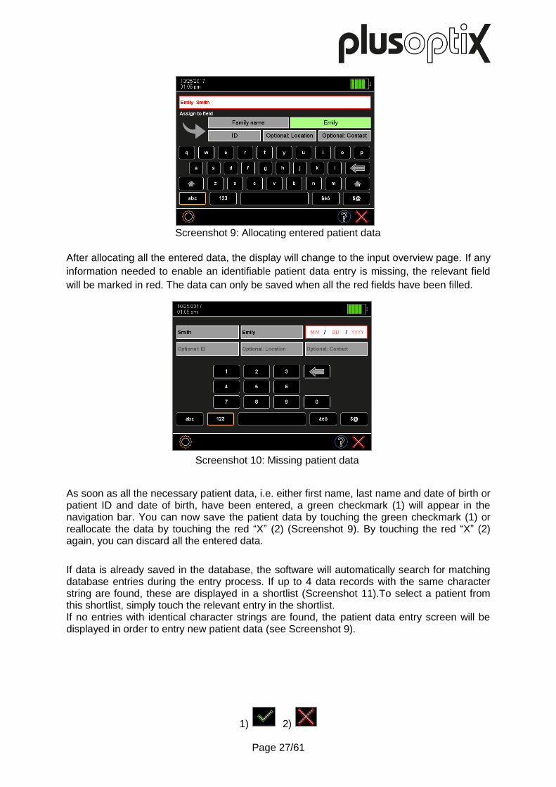
To prepare for a measurement, the patient data can also be entered or retrieve from the database before the measurement. The subsequently started measurement will then be performed under the previously entered or selected patient data. You do not have to switch between individual fields on the intuitive patient data entry screen. Simply enter the personal details of the patient into the entry field, separated by a space, e.g. Emily Smith.
To be able to clearly identify a patient in the database, the first name, last name and date of birth or a patient ID and date of birth must be entered. Information about the examination location and contact information are optional.
Now allocate the entered data by tapping the relevant field in order of the information:
“Emily” is the first name Tap the “First name” field
“Smith” is the last name Tap the “Last name” field
Screenshot 8: Entering patient data
Page 27/61
After allocating all the entered data, the display will change to the input overview page. If any
information needed to enable an identifiable patient data entry is missing, the relevant field
will be marked in red. The data can only be saved when all the red fields have been filled.
As soon as all the necessary patient data, i.e. either first name, last name and date of birth or patient ID and date of birth, have been entered, a green checkmark (1) will appear in the navigation bar. You can now save the patient data by touching the green checkmark (1) or reallocate the data by touching the red “X” (2) (Screenshot 9). By touching the red “X” (2) again, you can discard all the entered data.
If data is already saved in the database, the software will automatically search for matching database entries during the entry process. If up to 4 data records with the same character string are found, these are displayed in a shortlist (Screenshot 11).To select a patient from this shortlist, simply touch the relevant entry in the shortlist. If no entries with identical character strings are found, the patient data entry screen will be displayed in order to entry new patient data (see Screenshot 9).
1) 2)
Screenshot 10: Missing patient data
Screenshot 9: Allocating entered patient data

Page 28/61
After selecting an entry, you will see the patient data overview. If the patient has been retrieved from the database, all this patient’s saved measurement values are shown.
From the patient data overview, you can:
Measure the entered or retrieved patient in the appropriate age group by pressing the GO button or the trigger.
Touch the red “X” to return to the home page and enter a new patient or begin an anonymous measurement.
Screenshot 12: Patient data overview
Screenshot 11: Shortlist with entries with identical character strings
Deleting displayed patients including all measurements
(see Chapter 4.5)
New measurement
Deleting displayed measurements
(see Chapter 4.5)
Saved measurements

Page 29/61
4.3.2 Entering or retrieving patient data after the measurement
Patient data can be entered after a measurement to document the measurement results or existing or imported patient data can be retrieved from the database. An already performed measurement can thus be assigned to a specific patient in the database.
Note: A USB keyboard must be connected for entering the patient data.
You do not have to switch between individual fields on the intuitive patient data entry screen. Simply enter the personal details of the patient into the entry field, separated by a space, e.g. Emily Smith.
To be able to clearly identify a patient in the database, the first name, last name and date of birth or a patient ID and date of birth must be entered. Information about the examination location and contact information are optional.
Now allocate the entered data by tapping the relevant field in order of the information:
“Emily” is the first name Tap the “First name” field
“Smith” is the last name Tap the “Last name” field
Screenshot 13: Entering patient data
Screenshot 14: Allocating entered patient data

Page 30/61
After allocating all the entered data, the display will change to an overview page. If any
information needed to enable an identifiable patient data entry is missing, the relevant field
will be marked in red. The data can only be saved when all the red fields have been filled.
As soon as all the necessary patient data, i.e. either first name, last name and date of birth or patient ID and date of birth, have been entered, a green checkmark (1) will appear in the navigation bar. You can now save the patient data by touching the green checkmark (1) or reallocate the data by touching the red “X” (2) (Screenshot 13). By touching the red “X” (2) again, you can discard all the entered data.
If data is already saved in the database, the software will automatically search for matching database entries during the entry process. If up to 4 data records with the same character string are found, these are displayed in a shortlist (see Screenshot 16). To select a patient from this shortlist, simply touch the relevant entry in the shortlist. If no entries with identical character strings are found, the patient data entry screen will be displayed in order to entry new patient data (see Screenshot 13).
1) 2)
Screenshot 15: Missing patient data
Screenshot 16: Shortlist with entries with identical character strings
Page 31/61
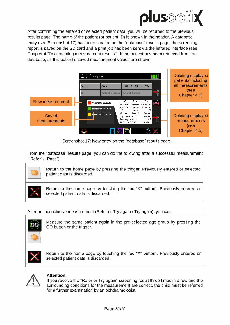
After confirming the entered or selected patient data, you will be returned to the previous
results page. The name of the patient (or patient ID) is shown in the header. A database
entry (see Screenshot 17) has been created on the “database” results page, the screening
report is saved on the SD card and a print job has been sent via the infrared interface (see
Chapter 4 “Documenting measurement results“). If the patient has been retrieved from the
database, all this patient’s saved measurement values are shown.
From the “database” results page, you can do the following after a successful measurement
(“Refer” / “Pass”):
Return to the home page by pressing the trigger. Previously entered or selected patient data is discarded.
Return to the home page by touching the red “X” button”. Previously entered or selected patient data is discarded.
After an inconclusive measurement (Refer or Try again / Try again), you can:
Measure the same patient again in the pre-selected age group by pressing the GO button or the trigger.
Return to the home page by touching the red “X” button”. Previously entered or selected patient data is discarded.
Attention: If you receive the “Refer or Try again” screening result three times in a row and the surrounding conditions for the measurement are correct, the child must be referred for a further examination by an ophthalmologist.
Screenshot 17: New entry on the “database” results page
Deleting displayed patients including all measurements
(see Chapter 4.5)
New measurement
Deleting displayed measurements
(see Chapter 4.5)
Saved measurements

Page 32/61
4.3.3 Importing patients from the EMR software before the measurement (CSV)
As an alternative to manual entry of the patient data, the “plusoptiX S12C” can also be integrated into your EMR software. The patient data is automatically transferred from your EMR software to the “plusoptiX S12C” before the measurement and the measurement results are automatically transferred back to your EMR software after the measurement.
You can download instructions about incorporating the “plusoptiX S12C” into your EMR software from our homepage (www.plusoptix.com).
Note: Your EMR software must support this interface to enable data transfer to work with your EMR software. Find out from the supplier of your EMR software whether this is compatible with the Plusoptix device.
4.3.4 Importing patient data via the USB interface
The patient data can be imported into the database through the USB interface in the form of a CSV table.
Note: Imported patient data is always added to existing entries in the database. No pre-existing data records are deleted.
The data fields of any CSV table being imported must:
- be separated with the separator selected in the settings – either “,” (comma) or “;” (semi-colon)
- contain 5 separators (a concluding separator at the end after “contact” can also be added) - follow this order: LastName,FirstName,DateOfBirth,ID,Location,Contact - contain either the last name, first name and data of birth or ID and date of birth in every
line; entry of the examination location and contact is optional - use the same data format as the date format selected in the settings (e.g. 31.01.2013 or
01/31/2013). Years have four digits.
A B C D E F
1 Last name First name Date of birth ID Location Contact
2 Chair Amber 03/02/2012
3 05/06/2011 0123456789
4 Smith Emily 06/24/2014 AB12CD24 Atlanta [email protected]
5 06/18/2009 A-12-B-34-C 030-123456
Figure 11: Sample of a CSV table
Note: The column headings in the first line are not imported.

Page 33/61
Save your CSV table under the name “input.csv” on a SD card in the directory “/db” and then connect this to the “plusoptiX S12C”. Then touch the data import (2) button in the settings (1). A list of all CSV tables in the “/db” directory will be shown. Select the CSV table to be imported and confirm your choice by touching the green checkmark (3) in the navigation bar.
Before the patient data is now imported, the “plusoptiX S12C” will automatically check whether the data records are correct (e.g. no figures in the “Name” field). However, muddled data entries (e.g. first names instead of last names) cannot be automatically recognised. You are prompted to check whether the patient data shown on the screen is in the correct order. If yes, now confirm the data import by touching the green checkmark (3) in the navigation bar.
1) 2) 3)

Page 34/61
4.4 Exporting data (only plusoptiX S12C)
All patient data and measurement values are archived in a database on the internal memory of the “plusoptiX S12C”. Back-up copies of this database can be saved.
Note: To avoid a loss of data, we recommend regularly making a back-up copy.
Press the button (1) in the settings. Select the file format you want for the data export:
CSV tables can be edited with all conventional spreadsheet programmes.
DB files are intended as back-up copies and can be used to restore the database. To restore the database, connect the USB storage with the exported db file in its directory “db” to the “plusoptiX S12C”. You will be asked whether the saved database should be restored. If there are several database in the main directory of the SD card, the most up-to-date (by save date) will be restored.
Note: When you restore a database, a back-up copy of the “plusoptiX S12C” database will first be saved to the SD card. Then, the “plusoptiX S12” database will be overwritten by the restoring database. The two databases will not be merged.
If an SD card is connected, a back-up copy will be saved to the SD card in the selected format. If no SD card is connected, a back-up copy will be saved in the selected format to a transfer directory (URL:\\px12-xxxx\transfer\). The “xxx” place marker stands for the last four numbers of the serial number. You will have access through the released transfer directory.
1)
Screenshot 18: Data export
Location: USB storage,
directory “db”
Location: Transfer directory
X

Page 35/61
4.5 Deleting entries from the database (only plusoptiX S12C)
Saved measurement values can be deleted from the database.
Touch the measurement that you want to delete and then touch the Delete button (1) at the right next to the label. Confirm the confirmation prompt with the green checkmark (2).
If you want to delete the patient along with all saved measurement values, touch the symbol (1) next to the entry fields and then confirm the confirmation prompt by touching the green checkmark (2).
If you do not want to delete the measurement values or patient, reject the selection by touching the red “X” (3) in the navigation bar. By touching the red “X” (3) or trigger again, you will return to the home page.
1) 2) 3)
Deleting displayed patients
including all measurements
Screenshot 19: Deleting entries from the database
Screenshot 20: Deleting patients from the database
Deleting displayed
measurements
Selecting the measurement
Deleting displayed
measurements

Page 36/61
5 Practical Tips
5.1 Adjust the settings
You can use the settings to adjust the “plusoptiX S12” to your requirements. You get to the settings by touching the gear wheel (1) in the navigation bar. By touching the red “X” (2), you can return to the screen, from which you originally called up the settings.
Adjust the basic settings See Chapter 0
Setting the date and time See Chapter 0
Selecting the language
Configuring the software and downloading the software update
See Chapter 5.7
Setting up the network access WLAN (only plusoptiX S12C)
See Chapter 5.5
Connection to your EMR software (only plusoptiX S12C)
See Chapter 4.3.3
Selecting the referral criteria See Chapter 5.3
Exporting data (only plusoptiX S12C)
See Chapter 4.4
Importing patient data (only plusoptiX S12C)
See Chapter 4.3.4
Deleting the database (only plusoptiX S12C)
See Chapter 4.5
Setting up the screen lock (only plusoptiX S12C)
See Chapter 5.3
1) 2)
Screenshot 21: Settings

Page 37/61
5.2 Adjust the basic settings
Touch the button (1) in the settings to access the basic settings.
Selection of the astigmatism display The astigmatism can be displayed as a plus cylinder or minus cylinder.
Setting the volume With a 0% setting, the warble sound is turned off.
Setting the screen brightness
Using commas or semi-colons as separators in the CSV files.
The set separator is used for all CSV files that are saved by the
“plusoptiX S12C”. Only CSV files that use the set separator can be imported.
Confirm your choice by touching the green checkmark (2) or reject the changes with the red “X” (3) in the navigation bar.
1) 2) 3)
Screenshot 22: Adjust the basic settings

Page 38/61
5.3 Selecting the referral criteria
Touch the button to choose the referral criteria (1) in the settings. There are five validated groups of referral criteria to choose from (see Screenshot 23).
These five groups are called ROC 1, ROC 2, ROC 3, ROC 4 and ROC 5. Each of these groups defines different, age-dependent thresholds, which lead to a “Refer” preventive test result. These five groups are shown along a schematic ROC (Receiver Operating Characteristic) curve. Select a group by touching the relevant button (2) and confirm by touching the green checkmark (3).
5.4 Setting up the screen lock (only plusoptiX S12C)
To protect the patient data stored in the “plusoptiX S12C” from unauthorised access, the screen can be locked. Touch the lock (4) in the settings.
Activating the screen lock:
- Touch the deactivated button with the lock (5). - Enter a six-digit PIN using the on-screen keyboard. - Then touch the green checkmark (3) to activate the screen lock or the red “X” (4) to
discard the entry. As soon as the screen lock is activated, the lock (1) will be seen in the navigation bar.
1) 2) 3) 4) 5) 6)
Screenshot 24: Setting up the screen lock
Screenshot 23: Selecting the referral criteria

Page 39/61
Locking the screen:
- Touch the lock (1) in the navigation bar to lock the screen. Once the screen is locked, it can only be unlocked by entering the six-digit PIN.
Note: The lock (1) can only be seen in the navigation bar if you have activated the screen lock in the settings.
Deactivating the screen lock:
- Touch the activated button with the lock (2) and - Enter your PIN - Then confirm by touching the green checkmark (3) or the red “X” (4) to discard the entry.
5.5 Setting up the network access WLAN (only plusoptiX S12C)
The “plusoptiX S12C” is equipped with a WLAN interface. This interface can be used to connect to a network. The activated WLAN connection is shown in the header (5).
Note: WLAN connection with the network can either be set up by entry of a static IP address, or automatic allocation of the IP address by a DHCP server.
The WLAN interface is deactivated in the factory settings. If the WLAN interface is activated, the LAN interface is automatically deactivated.
- Touch the button (1) in the settings to get to this screen.
- Touch the button (6) to activate the WLAN interface. The “plusoptiX S12C” then automatically searches for all available networks within its range and displays these. By touching the down arrow (7), you can view the list.
1) 2) 3) 4) 5) 6) 7)
Screenshot 25: Activating WLAN
Page 40/61
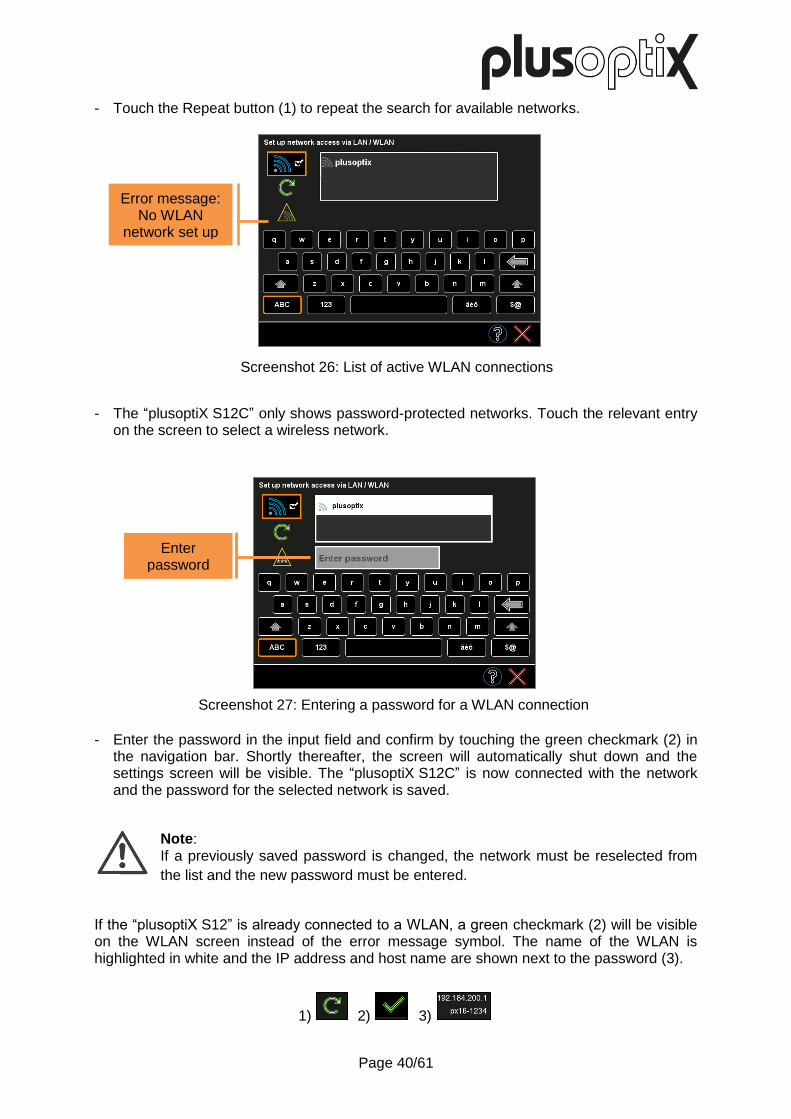
- Touch the Repeat button (1) to repeat the search for available networks.
- The “plusoptiX S12C” only shows password-protected networks. Touch the relevant entry on the screen to select a wireless network.
- Enter the password in the input field and confirm by touching the green checkmark (2) in
the navigation bar. Shortly thereafter, the screen will automatically shut down and the settings screen will be visible. The “plusoptiX S12C” is now connected with the network and the password for the selected network is saved.
Note: If a previously saved password is changed, the network must be reselected from
the list and the new password must be entered.
If the “plusoptiX S12” is already connected to a WLAN, a green checkmark (2) will be visible on the WLAN screen instead of the error message symbol. The name of the WLAN is highlighted in white and the IP address and host name are shown next to the password (3).
1) 2) 3)
Screenshot 26: List of active WLAN connections
Enter password
Screenshot 27: Entering a password for a WLAN connection
Error message: No WLAN
network set up

Page 41/61
Note: If you turn off the “plusoptiX S12C” when a WLAN is connected, it will automatically connect with the selected WLAN every time it is turned back on.
To deactivate the WLAN interface, touch the button (1). You will automatically return to the settings. If the WLAN connection is disconnected, a yellow warning triangle with an error message will be shown instead of the green checkmark (2).
This error message shows whether an incorrect password or no password at all has been entered.
This error message shows that the DHCP server has not allocated the “plusoptiX S12C” an IP address.
This error message shows that the WLAN router is outside the range of the “plusoptiX S12C”, that there is no WLAN network set up or that the password for the network has changed. In this case, enter the new password.
1) 2)
Screenshot 28: Viewing active network connection
WLAN active
WLAN network set-up
IP address and host name

Page 42/61
5.6 Mini-USB interface Attention: To avoid damage to the device, do not connect any external devices other than an IEC 60601-1-approved computer to the mini-USB interface.
The device features a 5-pole-Mini-B-USB port. This is used by Plusoptix as part of the production process and in the case of a service and warranty issue. The connection over a Mini-USB cable is available for all S12 devices from the supplement “01F” in the serial number (Example: S/N 120xS-01F-xxxx xxxx). Because of the technical design, devices with older serial numbers are not compatible. It can be used to connect the device to your workplace computer. The device is portrayed as removable medium in your Windows-Explorer or Apple Finder.
Note:
All interfaces are installed upside down. Therefore all connectors must also be
turned around before being inserted (i.e. USB symbol faces downwards).
The connection with Mini-USB is used for:
- Printing a screening report (PDF file) – see chapter 4.2 URL: removable medium:\pdf
- Download Software Updates – see chapter 5.7
Note: To use the Mini-USB interface the WLAN interface must be deactivated. If there is an active WLAN connection, the Mini-USB interface is deactivated.
5.7 Downloading software updates
We recommended checking regularly to see if there is a new software version to download. The latest software version can either be downloaded via your workplace computer or via the LAN/WLAN interface directly to your “plusoptiX S12”. If your “plusoptiX S12” is already up-to-date, the message “The software version is up-to-date” will be shown. To download a software update, you will need an empty SD card.

Page 43/61
Attention: During the update process, all the data saved on the SD card will be deleted. For this reason, make sure you only use an empty SD card.
Note: After the software update has been installed, you will see a message about formatting the SD card. Confirm this message if you want to use the SD card to save screening reports after the update. Do not format it if you want to use it to update further “plusoptiX S12” devices.
Downloading software updates on the workplace computer
If you cannot establish an internet connection to the “plusoptiX S12”, the software update can also be downloaded to the workplace computer.
The latest software update and instructions on downloading the file can be found on our homepage www.plusoptix.com.
Downloading the software update directly onto the “plusoptiX S12” (WLAN or Mini-USB)
If you want to download the software update using WLAN or Mini-USB, take the following precautions for updating the software:
- Insert an empty SD card - Connect the plusoptiX device to the power network - Establish internet access (either over a WLAN-connection or over a Mini-USB cable to
your workplace computer)
- Touch the button to configure the software (1) in the settings. - Then touch the button (2) to download the latest software - Confirm with the green checkmark (3). You will be guided through the download (see
figure 12).
When downloading, the software update will be saved on the SD card and a confirmation will be displayed. As soon as you touch OK, the “plusoptiX S12” will automatically restart and install the software update saved on the SD card.
1) 2) 3)
Screenshot 29: Downloading software updates

Page 44/61
Downloading Software Update via WLAN (only plusoptiX S12C)
With active WLAN-connection you will be guided through the update with the help of the following status messages (see Figure 16).
Note: Depending on the signal strength of the WLAN- and the Internet connection, a software update over WLAN can take about 30-40 min.
Downloading Software Update via Mini-USB-cable
If there is no WLAN-connection available, the software update can be downloaded via Mini-USB cable (see Figure 17).
Note: Depending on the internet connection, a software update via Mini-USB cable can take about 15-25 min.
Figure 12: Downloading the software update via WLAN

Page 45/61
Please open Windows Explorer or Apple Finder and choose the corresponding file folder. File access with URL: Removable medium\pdf
Start Plusoptix Image Downloader to download the Software Update.
Figure 13 : Software Update via Mini-USB-cable
Action recommendations on the device Action recommendations on your workplace computer
Parallel processes

Page 46/61
5.8 Connecting the USB keyboard and mouse (optional) To ease patient data entry on the “plusoptiX S12”, it is necessary to connect a conventional USB keyboard. Connect your input device with the USB interface of the “plusoptiX S12”. You can also connect wireless input devices instead of cabled ones.
Note: All device ports are located upside down, that is, the plugs must also be turned around before being inserted (i.e. the USB symbol faces downwards).
If a connected mouse or keyboard is not working, please check whether the USB keyboard or mouse is switched on, connected with the “plusoptiX S12” and whether the batteries are inserted. If your input device still doesn’t work, this means it is not supported by the drivers installed in the “plusoptiX S12”. Use input devices from another manufacturer instead in this case.
Note: Non-functioning external input devices do not constitute a service or warranty case!

Page 47/61
6 Troubleshooting guide
Over 80% of all service inquiries relate to errors when switching on the “plusoptiX S12”, errors when operating the screen or measuring interruptions, which have been caused by errors in using the “plusoptiX S12”. These errors can only be attributed to the “plusoptiX S12” in very rare cases. In the following chapters, you will find step-by-step instructions about diagnostics and troubleshooting.
6.1 Trouble-shooting when switching device on a) The device cannot be switched on
If the device cannot be switched on, connect the power adapter to a plug and check whether the green LED lights up on the upper side of the power adapter. Now connect the 12V charging cable to the device. If the device now switches on, check whether rechargeable batteries are inserted correctly (see chapter 2.3 “Inserting and charging the rechargeable batteries”).
b) The device switches off again immediately
If the device switches off again immediately, the rechargeable batteries are likely to be discharged. Connect the 12V charging cable to charge the batteries. Check whether the power supply unit is receiving current (green LED on top of the power adapter lights up). You can use the device while it is being charged. To do so, simply switch the device on while the 12V charging cable is connected.

Page 48/61
6.2 Malfunctions when using touch screen a) Screen switches off suddenly
To save power, the device automatically switches the screen off after some time. Touch the screen to activate it again. If the screen is not activated by touching it, the device has switched off automatically. Simply switch it back on again by pressing the On/Off button.
Note: Define in Basic settings after how many seconds the device should automatically switch off the screen and after how many minutes it should automatically switch off itself.
b) Buttons on screen do not function
plusoptiX S12C: Place the fingertip of your index finger flat on the screen to select a button. Do not tap on the screen with the fingertip or finger nail. plusoptiX S12R: Tap on the screen with the fingertip or finger nail.
Every time you touch the screen a small mouse pointer indicates the place in which the screen has been "hit". If you are unable to select a button by touching the screen, check the position of the mouse pointer on the screen. Ensure that the mouse pointer hovers above the button. Please read chapter 5.8 „Connecting the USB keyboard and mouse (optional)" if you prefer this option.
c) Screen flickers during a measurement
If the camera lens of the device is too close to a person or an object, the integrated infrared LEDs automatically switch off. The camera image on the screen is then not exposed and shows up black. After a second, the devices switches on the infrared LEDs again and if the person or object is still too close to the camera, only a short white flicker appears on the screen before the infrared LEDs are switched off again.
Simply increase the distance between the camera lens and the person or object, and the exposure of the camera image will automatically adjust again.
Page 49/61
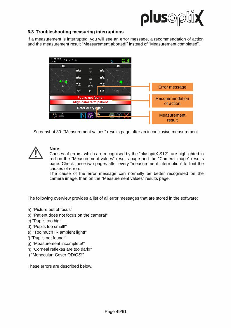
6.3 Troubleshooting measuring interruptions
If a measurement is interrupted, you will see an error message, a recommendation of action and the measurement result “Measurement aborted!” instead of “Measurement completed”.
Screenshot 30: “Measurement values” results page after an inconclusive measurement
Note: Causes of errors, which are recognised by the “plusoptiX S12”, are highlighted in red on the “Measurement values” results page and the “Camera image” results page. Check these two pages after every “measurement interruption” to limit the causes of errors. The cause of the error message can normally be better recognised on the camera image, than on the “Measurement values” results page.
The following overview provides a list of all error messages that are stored in the software:
a) "Picture out of focus"
b) "Patient does not focus on the camera!"
c) "Pupils too big!"
d) "Pupils too small!"
e) "Too much IR ambient light!"
f) "Pupils not found!"
g) "Measurement incomplete!"
h) "Corneal reflexes are too dark!"
i) “Monocular: Cover OD/OS!”
These errors are described below.
Error message
Recommendation of action
Measurement result

Page 50/61
In this example, the patient is too far away. Other than the eyes, half of the patient’s
face can be see in the camera image.
In this example, the patient is too close to the “plusoptiX S12”. Both eyes are close to
the left and right edges of the camera image.
a) Picture out of focus
Cause: This error message is shown if the measuring distance is not right. Reason: The camera is well focussed on the measuring distance of 1 meters and
measures from a distance of between 95 and 105 cm. Tip: You can detect the correct measuring distance when the camera image is shown
in high definition on the screen and you can see each individual hair of the eyebrows and eyelashes.

Page 51/61
In this example, the patient is looking to the left of the camera (when seen from the
patient). The red points in the gaze map highlight this line of vision.
In this example, the pupils are greater than 8.0 mm.
b) Patient does not focus on hte camera!
Cause: This error message is shown if the patient is not looking at the hexagon on the
camera face. Reason: To avoid incorrect refraction measurement values in the periphery of the eyes,
both eyes must be facing the middle of the camera. Tip: Position the child so that their knees and nose are facing the camera. Do not use
any external fixation aids and stay calm! Both corneal reflexes must be seen in the centre of the pupil middle on the camera image. Only green points should be seen in the two gaze maps on the “Measurement values” results page.
c) Pupils too big!
Cause: This error message is shown if one or both pupil diameters are greater than 8.0
mm. Reason: The pupil reflexes will be overexposed if the pupils are too large. In this case, the
measurement will be interrupted inconclusively. If measurement values are still shown, these have a greater tolerance.
Tip: Brighten the examination room so that the pupils become smaller.

Page 52/61
In this example, the pupils are smaller than 4.0 mm.
In this example, the sun is shining in the patient’s face from the left. This can be seen
from the shadows over the nose.
d) Pupils too small!
Cause: This error message is shown if one or both pupil diameters are smaller than 4.0
mm. Reason: The pupil reflexes will be underexposed if the pupils are too small. In this case,
the measurement will be interrupted inconclusively. If measurement values are still shown, these have a greater tolerance.
Tip: Make the examination room darker so that the pupils get bigger. Avoid an excessively dark examination room, as children will feel unhappy and try and look around. The examination room should be at least so bright that you could read a newspaper.
e) Too much IR ambient light!
Cause: This error message is shown if there is too much infrared light in the examination
room. Reason: The measurement is carried out using infrared light and other sources of infrared
light (e.g. sun, halogen spotlights, lightbulbs etc.) cause disturbances. Tip: Close the curtains to block out the sunlight, turn off or dim heat-radiating light
sources or point them in a different direction.

Page 53/61
In this example, neither pupil can be seen completely on the camera image.
In this example, the right pupil (OD) is partially covered by a media opacities (cataract).
f) Pupils not found!
Note: The error message “Pupils not found!” can have many other causes (e.g. scars on the cornea, media opacities, cataracts, keratoconus, retinal detachments, etc.). For this reason, the camera image must be checked in case of this error message.
Cause: This error message is displayed if the software cannot recognise pupils in the camera image, the pupil reflex looks unusual or the pupils are partially covered by reflections, hair, eyelashes or eyelids.
Reason: To be able to take a measurement, both pupils must be fully visible and the infrared light of the camera must be reflected by the retina.
Tip: Brush long hair out of the face before taking the measurement. Ask the child to open their eyes wide or lift their chin if they are looking shyly to the ground.
g) Measurement incomplete!

Page 54/61
In this example, the right pupil is covered by the upper eyelashes and the left pupil by hair.
In this example, the patient is sitting at an angle to the camera and looking over his right shoulder a little. You can see this from the fact that his nose can be seen from the side.
In this example, the patient has tilted their head downwards and is looking up into the
camera. The pupils are partially covered by the upper eyelids.
Note: The error message “Measurement incomplete!” can have many other causes (e.g. scars on the cornea, media opacities, cataracts, keratoconus, retinal detachments, etc.). For this reason, the camera image must be checked in case of this error message.
Cause: This error message is displayed when the measurement has started, but could
not be completed. Reason: After a measurement has begun, this must be completed within 20 seconds. Tip: Start the measurement again immediately by pressing the trigger twice.
Position the child so that their knees and nose are facing the camera. Ask the child to lift their head or hold the “plusoptiX S12” lower down.

Page 55/61
In this example, too little infrared light is reflected from the retina.
h) Corneal reflexes are too dark!
Cause: This error message is displayed if the corneal reflexes are too dark. Reason: The measurement is carried out with infrared light which is reflected from the
retina. If too little light comes back from the retina, no measurement can be taken.
Tip: Darken the examination room so that the pupils become larger and more infrared light can return to the camera.
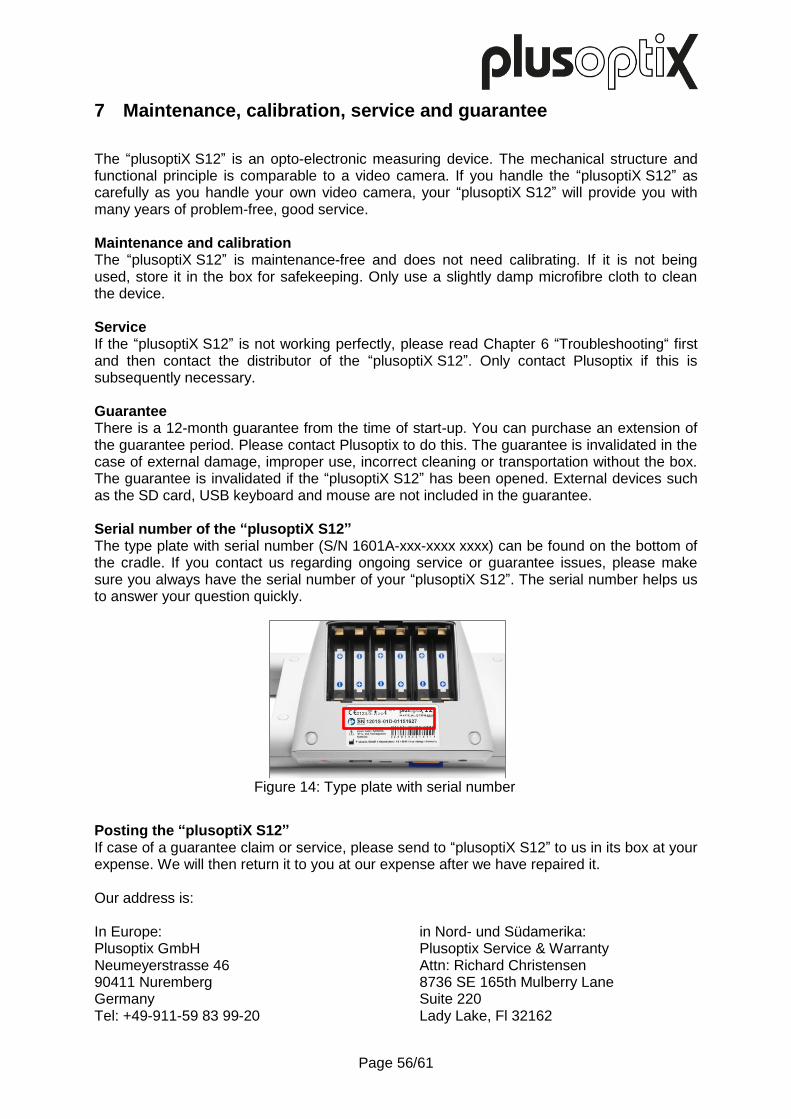
Page 56/61
7 Maintenance, calibration, service and guarantee
The “plusoptiX S12” is an opto-electronic measuring device. The mechanical structure and functional principle is comparable to a video camera. If you handle the “plusoptiX S12” as carefully as you handle your own video camera, your “plusoptiX S12” will provide you with many years of problem-free, good service. Maintenance and calibration The “plusoptiX S12” is maintenance-free and does not need calibrating. If it is not being used, store it in the box for safekeeping. Only use a slightly damp microfibre cloth to clean the device. Service If the “plusoptiX S12” is not working perfectly, please read Chapter 6 “Troubleshooting“ first and then contact the distributor of the “plusoptiX S12”. Only contact Plusoptix if this is subsequently necessary. Guarantee There is a 12-month guarantee from the time of start-up. You can purchase an extension of the guarantee period. Please contact Plusoptix to do this. The guarantee is invalidated in the case of external damage, improper use, incorrect cleaning or transportation without the box. The guarantee is invalidated if the “plusoptiX S12” has been opened. External devices such as the SD card, USB keyboard and mouse are not included in the guarantee. Serial number of the “plusoptiX S12” The type plate with serial number (S/N 1601A-xxx-xxxx xxxx) can be found on the bottom of the cradle. If you contact us regarding ongoing service or guarantee issues, please make sure you always have the serial number of your “plusoptiX S12”. The serial number helps us to answer your question quickly.
Posting the “plusoptiX S12” If case of a guarantee claim or service, please send to “plusoptiX S12” to us in its box at your expense. We will then return it to you at our expense after we have repaired it. Our address is: In Europe: Plusoptix GmbH Neumeyerstrasse 46 90411 Nuremberg Germany Tel: +49-911-59 83 99-20
in Nord- und Südamerika: Plusoptix Service & Warranty Attn: Richard Christensen 8736 SE 165th Mulberry Lane Suite 220 Lady Lake, Fl 32162
Figure 14: Type plate with serial number

Page 57/61
8 Technical details about the “plusoptiX S12”
Measurement values
Metered value Measurement range and tolerance
Sphere -7 to +5 dpt in 0.25 dpt steps ± 0.25 dpt
Cylinder -7 to +5 dpt in 0.25 dpt steps ± 0.25 dpt
Axis 1 to 180° in 1° steps ± 15°
Spherical equivalent -7 to +5 dpt in 0,25 dpt increments ± 0,25 dpt
Pupil diameter 4 to 8 mm in 0.1 mm steps ± 5%
Gaze asymmetry 0 to 25° in 0.1° steps ± 5°
Interpupillary distance 25 to 85 mm in 0.1 mm steps ± 5%
Interfaces and standards
Interfaces USB, IR
WLAN (only plusoptiX S12C)
“plusoptiX S12C” screen Diagonal 5.7‘‘, aspect ratio 4:3 (640 x 480 pixels) Capacitive contact sensor
“plusoptiX S12R” screen Diagonal 4.3‘‘, aspect ratio 5:3 (800 x 480 pixels) Resistive contact sensor
Standards EN 60601-1
IR Plusoptix devices use infrared light with a wavelength of 870nm and a maximum intensity of 135mW/sr.
WLAN interface standards:
Physical layer Supports 802.11 b and g standards
Network architecture types Communication with cabled networks via access points
Security WPA and WPA2
Transmit power 802.11b/g: 50 mW (+17 dBm) typically
Frequency range 2,400 - 2,4897 GHz
Operating channels 1-11 for North America and other, 1-13 for Europe and other
Channels Supports all channels of 802.11d-APs.
RX sensitivity -86 dBm typically @ 11 Mbps, -82 dBm @ 6 Mbps, -69 dBm @ 54 Mbps
Data rates 802.11g: 6, 9, 12, 18, 24, 36, 48, 54 Mbps 802.11b: 1, 2, 5.5, 11 Mbps
Power supply
Only use the GSM36P12-P1J power supply provided.
Medical power adapter (GSM36P12-P1J power supply)
Input 100 - 240 VAC, 50/0 Hz, 0,9 - 0,45 A
Output 12 VDC, 3A, 36 W max.
Rechargeable batteries (Panasonic BK – 3MCCE 1,2V)
Type / Size Nickel metal hydride NiMH / AA HR6
Wattage / Number
1900 mAh / 6 pieces

Page 58/61
Environmental conditions for operation and storage The plusoptiX 12 has been designed for the environment category “environment in areas of domestic health care”. The “plusoptiX S12” can be stored in its box. Do not put the box near heat sources (radiators, fan heaters, etc.). When you remove the “plusoptiX S12” from its box for use, do not place it in the sunlight.
Storage Temperature 0 to +50°C
Humidity 10 to 80% non-condensing
Operation Temperature +10 to +50°C
Humidity 20 to 80% non-condensing
Max. Height Max. storage height <2000m (78,740’’)
Max. operational height
<2000m (78,740’’)
Dimensions and weight with and without the box
plusoptiX S12C without cardboard box
Size 5½ x 10¼ x 5½ in (140 x 260 x 140 mm)
Weight 35,27 oz (1,0 kg)
plusoptiX S12C in cardboard box
Size 9¾ x 17 x 10¾ in (240 x 430 x 270 mm)
Weight 88,18 oz (2,5 kg)
plusoptiX S12R without cardboard box
Size 6 x 7¾ x 5¼ in150 (x 200 x 135 mm)
Weight 28 oz (0,8 kg)
plusoptiX S12R in cardboard box
Size 10½ x 17 x 9¾ in (270 x 430 x 250 mm)
Weight 74 oz (2,3 kg)
Manufacturer’s declaration about electromagnetic compatibility (EMC) The “plusoptiX 12” is intended for use in the electromagnetic environments listed below. Owners and holders of the “plusoptiX 12” are responsible for guaranteeing this environment.
This product conforms to the EMC standard (IEC 60601 -1 -2).
Note: This equipment has been tested and found to comply with the limits for a Class B digital device, pursuant to part 15 of the FCC Rules. These limits are designed to provide reasonable protection against harmful interference in a residential installation. This equipment generates, uses and can radiate radio frequency energy and, if not installed and used in accordance with the instructions, may cause harmful interference to radio communications. However, there is no guarantee that interference will not occur in a particular installation. If this equipment does cause harmful interference to radio or television reception, which can be determined by turning the equipment off and on, the user is encouraged to try to correct the interference by one or more of the following measures:
Reorient or relocate the receiving antenna
Increase the separation between the equipment and receiver
Connect the equipment into an outlet on a circuit different from that to which the receiver is connected
Consult the dealer or an experienced radio/TV technician for help

Page 59/61
Emissions Test Conformity Electromagnetic environment - Instructions
RF Emission CISPR 11 Group 1 The radiation is low and causes no interferences with electronic devices found nearby.
RF Emission CISPR 11 Category B
The “plusoptiX 12” can be used in all areas which are connected to the public mains supply.
Harmonic Emissions IEC 61000-3-2
Category A
Voltage fluctuations / Flicker IEC 61000-3-3
Complies
Immunity Test IEC 60601 test values Conformity values Electromagnetic environment - Instructions
ESD IEC 61000-4-2 ± 8 kV contact ± 2, 4, 8, 15 kV air
± 8 kV contact ± 2, 4, 8, 15 kV air
The floor should be made of wood, ceramic or stone. If the floor is covered with a synthetic material, the relative air humidity should not be less than 30%.
Electrical fast transient / burst IEC 61000-4-4
± 2 kV ± 2 kV
Only plugs that are usually available in domestic or clinical areas should be used.
Surge IEC 61000-4-5
± 0.5 kV ± 1 kV ± 2 kV
± 0.5 kV ± 1 kV ± 2 kV
Only plugs that are usually available in domestic or clinical areas should be used.
Voltage dips, short interruptions on power supply input lines IEC 61000-4-11
0% 0.5 cycles @ 0°, 45°, 90°, 135°, 180°, 225°, 270°, 315° 0% 1 cycle 70% 25 cycles
0% 250 cycles
0% 0.5 cycles @ 0°, 45°, 90°, 135°, 180°, 225°, 270°, 315° 0% 1 cycle 70% 25 cycles 0% 250 cycles
Only plugs that are usually available in domestic or clinical areas should be used.
Power frequencies and magnetic fields IEC 61000-4-8
30 A/m, 50/60Hz 30 A/m, 50/60Hz Magnetic fields should not exceed the usual areas.

Page 60/61
Immunity test Testing level acc. to IEC 60601
Conformity results Electromagnetic environment – Instructions
Conducted RF disturbances IEC 61000-4-6
3 V 0.15 MHz – 80 MHz 6 V in ISM and amateur radio bands between 0.15 MHz and 80 MHz 80 % AM at 1 kHz 3 V 0.15 MHz – 80 MHz 6 V in ISM and amateur radio bands between 0.15 MHz and 80 MHz 80 % AM at 1 kHz 120V / 60 Hz 230V / 50 Hz
3 V 0.15 MHz – 80 MHz 6 V in ISM and amateur radio bands between 0.15 MHz and 80 MHz 80 % AM at 1 kHz 3 V 0.15 MHz – 80 MHz 6 V in ISM and amateur radio bands between 0.15 MHz and 80 MHz 80 % AM at 1 kHz 120V / 60 Hz 230V / 50 Hz
Portable and mobile radio equipment must not be operated in a distance to „plusoptiX 12“ (including the electrical lines) less than the recommenced safe distance calculated using the appropriate equation for the transmission frequency. Recommended safe distance: d=(3.5/10) x √ P d=(3.5/10) x √ P 80MHz - 800MHz d=(7/10) x √ P 800MHz – 2.7GHz where P is the maximum output power rating of the transmitter in watts (W) as indicated by the transmitter manufacturer and “d” is the recommended safe distance in metres (m). The field strength of fixed RF transmitters as determined by a site survey should be less than the compliance level in each frequency range. Interference may occur in the vicinity of equipment marked by the symbol shown.
Radio-frequency electromagn. fields IEC 61000-4-3
10 V/m 80 MHz - 2.7GHz 80% AM, 1KHz 27 V/m 385 MHz PM 50%, 18 Hz 28 V/m 450 MHz PM 50%, 18 Hz 9 V/m 710,745,780 MHz PM 50%, 217 Hz 28 V/m 810, 870, 930 MHz PM 50%, 18 Hz 28 V/m 1720, 1845, 1970 MHz PM 50%, 217 Hz 28 V/m 2450 MHz PM 50%, 217 Hz 9 V/m 5240, 5500, 5785 MHz PM 50%, 217 Hz
10 V/m 80 MHz - 2.7GHz 80% AM, 1KHz 27 V/m 385 MHz PM 50%, 18 Hz 28 V/m 450 MHz PM 50%, 18 Hz 9 V/m 710,745,780 MHz PM 50%, 217 Hz 28 V/m 810, 870, 930 MHz PM 50%, 18 Hz 28 V/m 1720, 1845, 1970 MHz PM 50%, 217 Hz 28 V/m 2450 MHz PM 50%, 217 Hz 9 V/m 5240, 5500, 5785 MHz PM 50%, 217 Hz
COMMENT 1 At 80 MHz and 800 MHz, the higher frequency range applies. COMMENT 2 These guidelines may not apply in all situations. Electromagnetic propagation is affected by absorption and reflection from structures, objects and people.

Page 61/61
Attention:
Portable RF communications equipment (including peripherals such as antenna
cables and external antennas) should be used no closer than 30 cm (12 inches)
to any part of the plusoptiX 12, including cablesspecified by the manufacturer.
Otherwise, degradation of the performance of this equipment could result. The
plusoptiX 12 is not compatible to HF SURGICAL EQUIPMENT.
Recommended safety distances between portable and mobile HF telecommunication devices and the “plusoptix 12”
The “plusoptiX 12” is intended for use in an electromagnetic environment with controlled HF disturbance variables. The customer
or user of the “plusoptiX 12” can contribute to avoiding electromagnetic disturbances, by complying with the minimum distance
between portable and mobile HF telecommunication devices (transmitters) and the “plusoptiX 12” – depending on the output
power of the communication device, as stated below.
Maximum output power of the
transmitter in W
Safety distance depending on the transmission frequency (in meters)
150 kHz - 80MHz d = 0.35 √ P
80 MHz - 800MHz d = 0.35 √ P
800 MHz - 2,7GHz d = 0.7 √ P
0.01 0.035 0.035 0.07
0.1 0.11 0.11 0.22
1 0.35 0.35 0.7
10 1.11 1.11 2.21
100 3.5 3.5 7
For transmitters, whose maximum nominal output is not stated in the above table, the recommended safety distance in meters
(m) can be calculated using the equation from the relevant column, wherein P equals the maximum nominal output of the
transmitter in watts (W) as per information by the transmitter’s manufacturer.
COMMENT 1 At 80 MHz and 800 MHz, the higher frequency range applies.
COMMENT 2 These guidelines may not be applicable in all cases. The distribution of electromagnetic quantities is influenced by
absorption and reflections from buildings, objects and people.