mobile vision screener plusoptix s12 - good-lite · mobile vision screener plusoptix s12 user...
TRANSCRIPT
Page 1/40
Mobile Vision Screener plusoptiX S12
User Manual
Release: August 1, 2013
Plusoptix GmbH Neumeyerstrasse 48
90411 Nuremberg Germany
www.plusoptix.com
Read this user manual prior to initial operation! This user manual explains the basic functions of the device. Once the device is switched on, supplementary information can be accessed by touching the blue “i” button on screen. This supplementary information describes on-screen displays in more detail.

Page 2/40
Content
1. Intended use and responsibility of the owner ................................................................... 4 2. Putting the device into operation ..................................................................................... 6
2.1. Checking scope of delivery .......................................................................................6 2.2. Getting to know the device .......................................................................................7 2.3. Inserting and charging batteries ...............................................................................9 2.4. Switching device on and off .................................................................................... 10 2.5. Screen display and help screen ............................................................................. 11
3. Performing a measurement ........................................................................................... 12 3.1. Consider the environment ...................................................................................... 12 3.2. Start a measurement .............................................................................................. 13 3.3. Enter patient data ................................................................................................... 14 3.4. Start and align camera ........................................................................................... 16 3.5. Check and document measurement results ........................................................... 17 3.6. Perform next measurement .................................................................................... 22
4. Handling clues ............................................................................................................... 23 4.1. Holding camera and using neck strap .................................................................... 23 4.2. Retrieving, editing and deleting a patient from the database .................................. 24 4.3. Performing a „Two-Click-Measurement“ ................................................................. 25 4.4. Adjusting settings ................................................................................................... 26 4.5. Activating screen lock ............................................................................................. 27 4.6. Saving database backup, restoring database and generating reports .................... 28 4.7. Activating WLAN to connect wireless printer .......................................................... 29 4.8. Importing patient data ............................................................................................. 31 4.9. Touch screen is off (i.e. black) ................................................................................ 32 4.10. Touch screen is inactive (i.e. buttons don’t work) ................................................... 32 4.11. A date of birth can’t be entered .............................................................................. 32 4.12. SD-Card and USB-Memory Interfaces.................................................................... 33 4.13. Micro-USB Interface ............................................................................................... 33 4.14. Screening report and information column ............................................................... 34 4.15. Compatible printers ................................................................................................ 35 4.16. Using a stylus, mouse or keyboard ......................................................................... 36 4.17. EMR integration ..................................................................................................... 36 4.18. Aborted measurements – What is the meaning of error messages? ....................... 37
5. Maintenance, calibration, service and warranty ............................................................. 38 6. Technical specifications................................................................................................. 39
6.1. Measurements ....................................................................................................... 39 6.2. Interfaces and standards ........................................................................................ 39 6.3. Power supply and rechargeable batteries ............................................................... 39 6.4. Ambient conditions for operation and storage......................................................... 39 6.5. Size and weight with and without carrying case ...................................................... 39 6.6. Guidance and manufacturer´s declaration – electromagnetic emissions/ immunity 40

Page 3/40
Index of Pictures Picture 1: Device in carrying case ......................................................................................... 6 Picture 2: Direct viewing of device ......................................................................................... 7 Picture 3: Device in rear view ................................................................................................ 8 Picture 4: Device battery compartment view .......................................................................... 9 Picture 5: Toggle in between screen display and help screen...............................................11 Picture 6: Illustration of a measurement ...............................................................................12 Picture 7: Aligning the camera ..............................................................................................16 Picture 8: Overview of measurement result screens .............................................................17 Picture 9: Holding the camera and pressing the shutter ........................................................23 Picture 10: Screening report .................................................................................................34
Index of screenshots Screenshot 1: Home page ....................................................................................................10 Screenshot 2: Home page ....................................................................................................13 Screenshot 3: Enter patient date of birth ..............................................................................14 Screenshot 4: Enter patient first name ..................................................................................15 Screenshot 5: Check screening result screen .......................................................................18 Screenshot 6: Review video screen......................................................................................19 Screenshot 7: Save screening result screen .........................................................................20 Screenshot 8: Review database entries screen ....................................................................21 Screenshot 9: Home screen with last patient pre-selected ...................................................22 Screenshot 10: Select patient from short list .........................................................................24 Screenshot 11: Select age group 19-30 month for a "2-click-measurement" ........................25 Screenshot 12: Settings menu ..............................................................................................26 Screenshot 13: Set-up screen lock .......................................................................................27 Screenshot 14: Generate a report ........................................................................................28 Screenshot 15: Activate WLAN screen .................................................................................29 Screenshot 16: Listing of available WLAN ............................................................................29 Screenshot 17: Choosing Zebra printer ................................................................................30 Screenshot 18: Reviewing network connection ....................................................................30
Page 4/40
0123
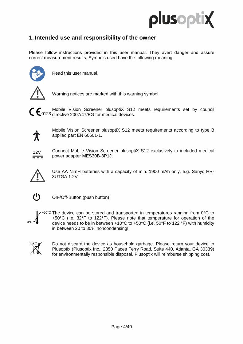
1. Intended use and responsibility of the owner
Please follow instructions provided in this user manual. They avert danger and assure correct measurement results. Symbols used have the following meaning:
Read this user manual.
Warning notices are marked with this warning symbol.
Mobile Vision Screener plusoptiX S12 meets requirements set by council directive 2007/47/EG for medical devices.
Mobile Vision Screener plusoptiX S12 meets requirements according to type B applied part EN 60601-1.
Connect Mobile Vision Screener plusoptiX S12 exclusively to included medical power adapter MES30B-3P1J.
Use AA NimH batteries with a capacity of min. 1900 mAh only, e.g. Sanyo HR-3UTGA 1.2V
On-/Off-Button (push button)
The device can be stored and transported in temperatures ranging from 0°C to +50°C (i.e. 32°F to 122°F). Please note that temperature for operation of the device needs to be in between +10°C to +50°C (i.e. 50°F to 122 °F) with humidity in between 20 to 80% noncondensing!
Do not discard the device as household garbage. Please return your device to Plusoptix (Plusoptix Inc., 2850 Paces Ferry Road, Suite 440, Atlanta, GA 30339) for environmentally responsible disposal. Plusoptix will reimburse shipping cost.
12V
0°C
+50°C

Page 5/40
Intended use The purpose of Mobile Vision Screener plusoptiX S12 is to detect vision disorders early (vision screening). Vision disorders can cause permanent loss of vision in one eye (amblyopia) if they are not detected and treated within the first years of life. To detect vision disorders, Mobile Vision Screener plusoptiX S12 measures sphere, cylinder, axis, gaze and pupil size of both eyes simultaneously. Based on these readings spherical equivalent, gaze symmetry and inter pupillary distance are calculated. Patients who should see an eye care professional are identified by comparing these measurement values to age dependent referral criteria. These patients show „refer“ as vision screening result automatically.
Measurement results don’t replace a comprehensive eye exam by an eye care professional. They can’t be used to prescribe glasses or contact lenses!
All children who are not treated by an eye care professional should be subject to vision screening. The first vision screening should be performed at one year of age. After that it should be repeated regularly because the eyes keep changing with growth of the child and new vision disorders can occur anytime. All children with a “refer” screening result should be presented to an eye care professional for a comprehensive eye exam.
False-positive and false-negative screening results may occur in any type of heath care screening.
Responsibility of the owner The owner has to assure that Mobile Vision Screener plusoptiX S12 is operated by trained users, only. Minimum user training requirements are to read this user manual and to participate in a hands-on training in manipulating the device. Hands-on training can be provided by a previously trained user. Hands-on training is offered by Plusoptix and authorized distributors, alternatively.
The owner is responsible for external devices connected to Mobile Vision Screener plusoptiX S12 comply with standards EN 60601-1 and EN 60601-1-1.
The owner is responsible for assuring that Mobile Vision Screener plusoptiX S12 is not opened in case of service or warranty. The device must not be opened by anyone other than Plusoptix or an authorized distributor. Opening the device exposes you to the risk of an electric shock. In addition the device loses its medical device certification and warranty coverage.
Page 6/40
2. Putting the device into operation
Thank you for purchasing Mobile Vision Screener plusoptiX S12! Plusoptix is world market leader in developing, manufacturing and distributing medical devices for vision screening in infants. We are happy to assist you if you have any further questions after reading this user manual.
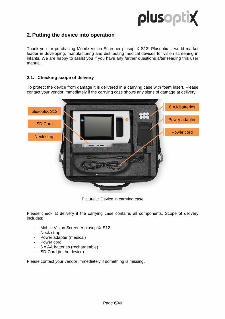
2.1. Checking scope of delivery To protect the device from damage it is delivered in a carrying case with foam insert. Please contact your vendor immediately if the carrying case shows any signs of damage at delivery.
Picture 1: Device in carrying case
Please check at delivery if the carrying case contains all components. Scope of delivery includes:
- Mobile Vision Screener plusoptiX S12 - Neck strap - Power adapter (medical) - Power cord - 6 x AA batteries (rechargeable) - SD-Card (in the device)
Please contact your vendor immediately if something is missing.
6 AA batteries
Power adapter
Power cord
plusoptiX S12
SD-Card
Neck strap
Page 7/40
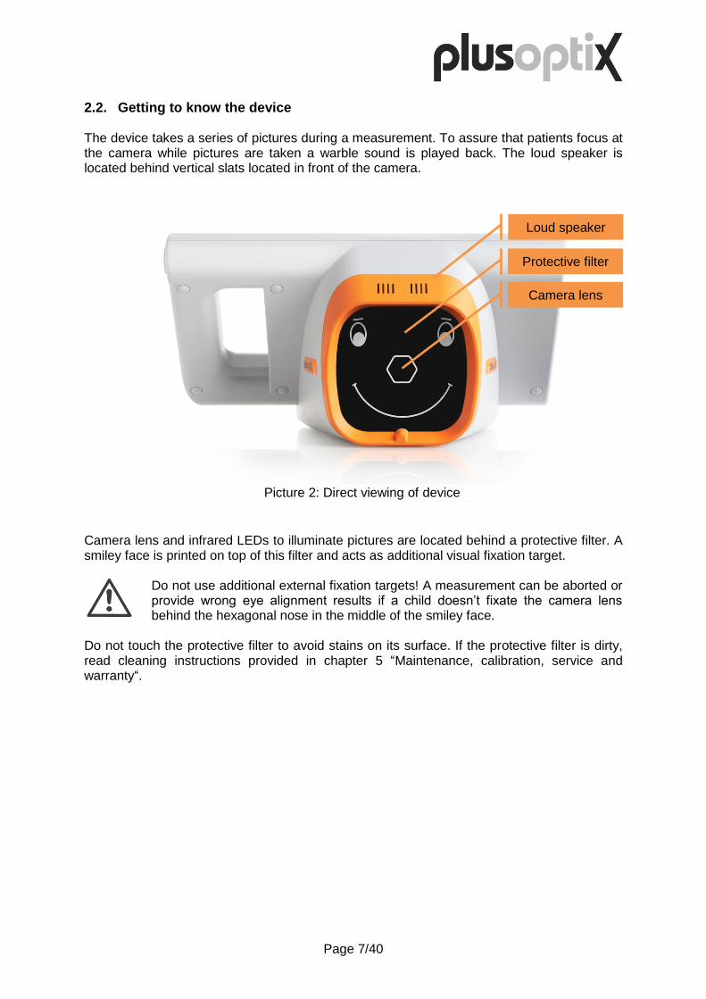
2.2. Getting to know the device The device takes a series of pictures during a measurement. To assure that patients focus at the camera while pictures are taken a warble sound is played back. The loud speaker is located behind vertical slats located in front of the camera.
Camera lens and infrared LEDs to illuminate pictures are located behind a protective filter. A smiley face is printed on top of this filter and acts as additional visual fixation target.
Do not use additional external fixation targets! A measurement can be aborted or provide wrong eye alignment results if a child doesn’t fixate the camera lens behind the hexagonal nose in the middle of the smiley face.
Do not touch the protective filter to avoid stains on its surface. If the protective filter is dirty, read cleaning instructions provided in chapter 5 “Maintenance, calibration, service and warranty“.
Loud speaker
Protective filter
Camera lens
Picture 2: Direct viewing of device

Page 8/40
A 5.7” capacitive touch screen is located at the rear of the camera. Simply touch the screen with one finger to activate a function that is displayed. Screen and touch sensor are protected by a thin glass panel. This glass panel can scratch in case of improper use or break in case the device falls down.
Place a soft cloth underneath the glass panel if you have to turn the device on its rear side, e.g. to insert or exchange batteries. Use neck strap to protect the device from falling down.
There are two orange color buttons, the On/Off button (on the right hand side underneath the touch screen) and the Shutter (on the handle to the right of the touch screen). The functioning of these buttons is explained in chapter 2.4 “Switching device on and off” and 3.4 “Start and align camera”. The device has 3 interfaces: USB, micro USB and SD card. All are located in the center underneath the touch screen. How to use these interfaces is explained in chapters 4.12 “SD-Card and USB-Memory Interfaces” and chapter 4.13 “Micro-USB Interface“.
All interfaces are positioned upside down. Therefore all media to be connected need to be turned upside down prior to connecting them to the device.
A 12 V female power input connector is located at the left hand side underneath the touch screen.
Touch screen
Shutter
On/Off button
Micro USB
SD-Card
12 V Input
USB
Picture 3: Device in rear view
Page 9/40
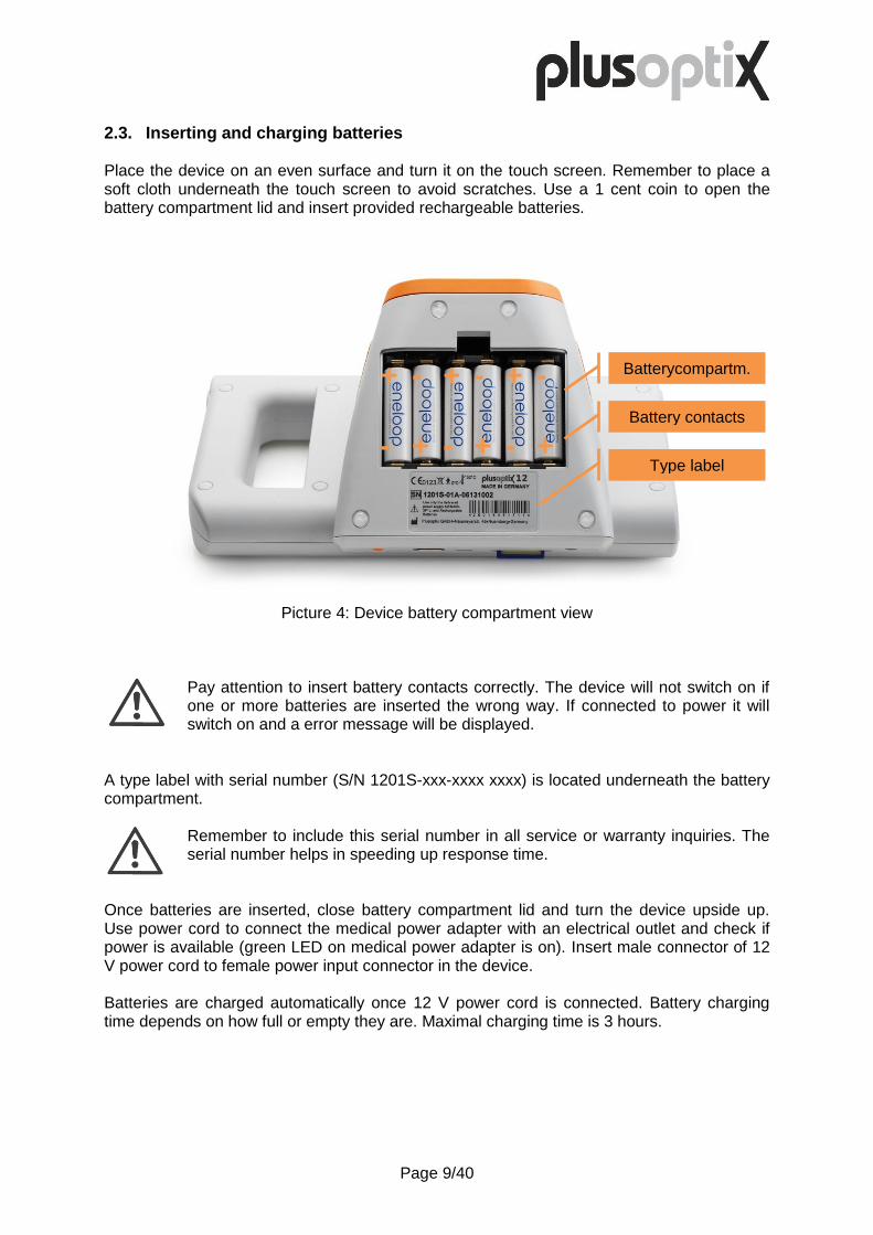
2.3. Inserting and charging batteries Place the device on an even surface and turn it on the touch screen. Remember to place a soft cloth underneath the touch screen to avoid scratches. Use a 1 cent coin to open the battery compartment lid and insert provided rechargeable batteries.
Picture 4: Device battery compartment view
Pay attention to insert battery contacts correctly. The device will not switch on if one or more batteries are inserted the wrong way. If connected to power it will switch on and a error message will be displayed.
A type label with serial number (S/N 1201S-xxx-xxxx xxxx) is located underneath the battery compartment.
Remember to include this serial number in all service or warranty inquiries. The serial number helps in speeding up response time.
Once batteries are inserted, close battery compartment lid and turn the device upside up. Use power cord to connect the medical power adapter with an electrical outlet and check if power is available (green LED on medical power adapter is on). Insert male connector of 12 V power cord to female power input connector in the device. Batteries are charged automatically once 12 V power cord is connected. Battery charging time depends on how full or empty they are. Maximal charging time is 3 hours.
+ - + - + -
- + - + - +
Batterycompartm.
Battery contacts
Type label

Page 10/40
2.4. Switching device on and off Press On/Off button shortly to switch device on. Touch screen will illuminate immediately and device is booting. Device will be operational after approximately 25 seconds, once the following home page is displayed.
If touch screen does not illuminate after switching device on, check if battery contacts are inserted correctly and switch the device on again. If touch screen still does not illuminate after pressing On/Off button although battery contacts are inserted correctly, connect 12 V power cord and switch it on again. The device can be operated while batteries are charging. Press On/Off button shortly to switch device off. The touch screen illumination turns off immediately and device shuts down. If touch screen illumination doesn’t turn off immediately, keep On/Off button pressed for 10 seconds until touch screen illumination turns off.
Device switches off automatically if not used. Timespan for automated power off can be defined in settings.
Device switches off automatically if batteries are empty, regardless of settings. In this case it can only be switched on with 12 V power cord connected.
Screenshot 1: Home page

Page 11/40
2.5. Screen display and help screen All screen displays are structured identically. A title bar is located on the top, an information area in the center and a navigation menu on the bottom.
Title bar provides date and time on the left hand side as well as WLAN (1) and battery status (2) on the right hand side. WLAN information (1) is displayed only if WLAN is activated in settings. A warning symbol (3) shows up as soon as WLAN reception is down or batteries need to be charged. A battery charging symbol (4) shows up once 12 V power cord is connected and batteries are charging. In the navigation menu active touch buttons are displayed in color and inactive touch buttons are shown grayed out. Touch the tools button (5) to access settings. Lock screen button (6) is only displayed if screen lock is activated in settings. Touch it to lock screen and prevent unauthorized access to patient data. Green checkmark button (7) confirms and saves whereas cancel button (8) aborts without saving. Touching blue information button (9) opens a help screen. Touch cancel button (8) to close help screen. Help screen explains touch buttons that are used in screen display. To save space these touch buttons are replaced by a consecutive number within the text (same as here). Numbers and touch buttons that are replaced are illustrated on the bottom of the help screen. All touch buttons that are illustrated on help screens are inactive. They are shown in color for better visualization, only.
1) 2) 3) 4) 5) 6) 7) 8) 9)
Picture 5: Toggle in between screen display and help screen
Title bar
Navigation menu
Information area
Buttons that are described in help
text
Help text

Page 12/40
3. Performing a measurement
Mobile Vision Screener plusoptiX S12 measures both eyes simultaneously in less than 1 second from 3.3 feet away. Patients with a very limited attention span such as infants 6 months and older can be measured this way. In addition simultaneous binocular readings provide reliable values for a left and right eye comparison.
3.1. Consider the environment The device uses infrared light to perform measurements. The same infrared light is part of sunlight and emitted by all incandescent light sources such as light bulbs and halogen spots. Infrared light is invisible to the human eye and nonhazardous. To obtain accurate measurements it is important to avoid disturbing infrared ambiance light in the examination room. Close curtains or shutters to keep sunlight out and switch off all incandescent light sources. However, examination room does not need to be dark. Cold light sources such as energy saving lamps or neon tubes do not disturb measurement results.
Picture 6: Illustration of a measurement A child needs to focus the device in order to take a measurement. Make sure that the child sits straight and does not turn its head over the shoulder. Knees and nose of the child should point at the device. An especially developed „warble“ sound attracts attention of infants to the device. This works well as long as infant’s attention is not diverted to other objects or persons in the exam room. Close the door and avoid all distracting activities such as clicking one’s fingers for example. Do not use additional fixation targets! Attention span of infants is very limited. Take advantage of the fact that the exam room is all new to the infant. An exotic “warble” sound in an unknown environment is always attractive to look at. Therefore enter patient data prior to inviting the infant to enter the exam room or enter patient data after the measurement. Avoid long explanations to the parents prior to taking a reading.

Page 13/40
3.2. Start a measurement After switching the device on you will see this home page on screen.
Screenshot 2: Home page In order to enter patient data, touch button (1). If patient data was entered previously it can be retrieved comfortably (see chapter 4.2 “Retrieving, editing and deleting a patient from the database“). A measurement can be performed anonymously if patient data is not needed because of privacy protection or to save time. Simply assign the patient to an age group on the left hand side of the screen (see chapter 4.3 “Performing a „Two-Click-Measurement“”) and press the shutter to start the measurement.
1)

Page 14/40
3.3. Enter patient data A patient’s date of birth needs to be entered prior to a measurement. This information is needed in order to compare measurement values with appropriate referral criteria.
Screenshot 3: Enter patient date of birth Use up- (1) and down (2) arrows to enter a date of birth. Date format can be adjusted in settings. Touching the up arrow once day count is 31 will start day count over at 1 and vice versa. This way it takes a maximum of 16 touches to set day correctly. Once a date of birth is entered, first and family name or a patient ID number need to be entered, additionally. This additional information is used as unique identifier of this patient within the database. Location and contact information can be entered, optionally. This information is not necessary to perform a measurement. Touch right (3) and left (4) buttons to navigate to these tabs.
1) 2) 3) 4)

Page 15/40
Touch the tab of the next data to be entered to move on.
Screenshot 4: Enter patient first name Use on screen keyboard to enter patient information. Touch shift button (1) to change from lower to upper case and vice versa and backspace button (2) to delete a letter. Please read chapter 4.16 “Using a stylus, mouse or keyboard” in case manipulation of on screen keyboard is cumbersome. Once data is entered, a green checkmark is displayed on the left hand side of the tab (3). After all data is entered, press orange shutter to start a measurement.
Orange shutter will only start a measurement once all data is entered. Data needed is either: date of birth + first name + family name or: date of birth + ID number. Location and contact information is optional.
1) 2) 3)
Page 16/40
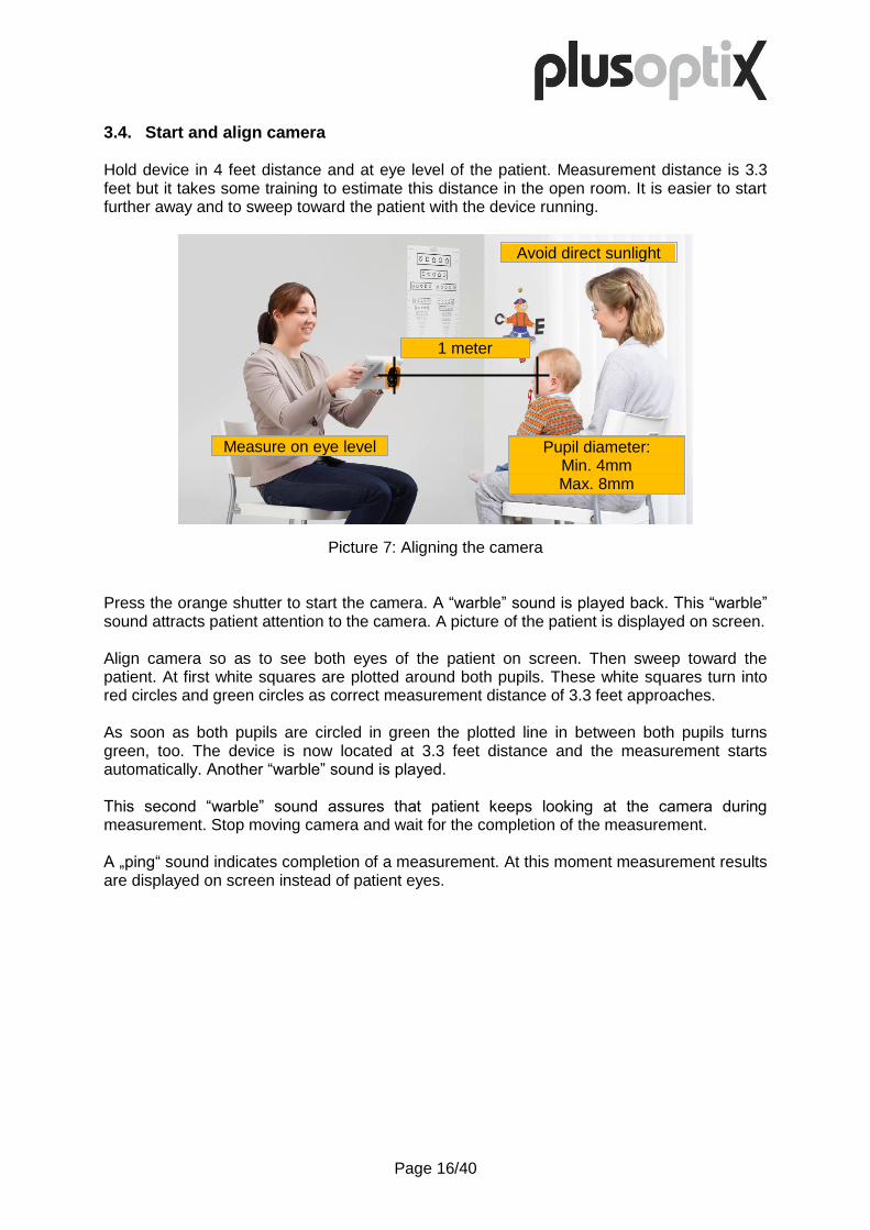
3.4. Start and align camera Hold device in 4 feet distance and at eye level of the patient. Measurement distance is 3.3 feet but it takes some training to estimate this distance in the open room. It is easier to start further away and to sweep toward the patient with the device running.
Picture 7: Aligning the camera Press the orange shutter to start the camera. A “warble” sound is played back. This “warble” sound attracts patient attention to the camera. A picture of the patient is displayed on screen. Align camera so as to see both eyes of the patient on screen. Then sweep toward the patient. At first white squares are plotted around both pupils. These white squares turn into red circles and green circles as correct measurement distance of 3.3 feet approaches. As soon as both pupils are circled in green the plotted line in between both pupils turns green, too. The device is now located at 3.3 feet distance and the measurement starts automatically. Another “warble” sound is played. This second “warble” sound assures that patient keeps looking at the camera during measurement. Stop moving camera and wait for the completion of the measurement. A „ping“ sound indicates completion of a measurement. At this moment measurement results are displayed on screen instead of patient eyes.
1 meter
Avoid direct sunlight
Measure on eye level Pupil diameter: Min. 4mm Max. 8mm

Page 17/40
3.5. Check and document measurement results Screen size is limited and therefore measurement results are presented on 4 screens for better readability. These 4 measurement result screens are:
Check screening result screen
Review video screen
Save screening result screen
Review database entries screen Touch orange arrows (1) and (2) located in navigation menu to toggle in between measurement result screens. An orange color dot in between these arrows indicates which of the 4 measurement result screens is displayed at present.
The only way to exit measurement result screens and to return to home screen (i.e. to start a new measurement) is to press the orange shutter.
1) 2)
Picture 8: Overview of measurement result screens
Page 18/40
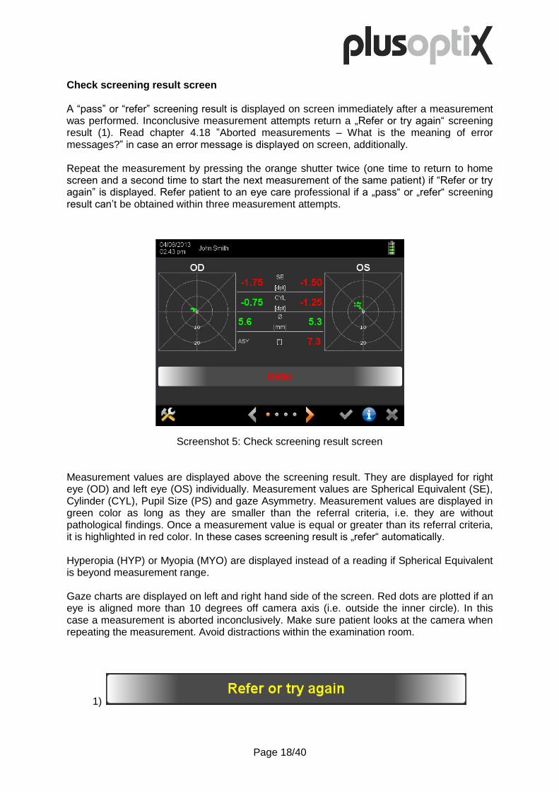
Check screening result screen A “pass” or “refer” screening result is displayed on screen immediately after a measurement was performed. Inconclusive measurement attempts return a „Refer or try again“ screening result (1). Read chapter 4.18 ”Aborted measurements – What is the meaning of error messages?” in case an error message is displayed on screen, additionally. Repeat the measurement by pressing the orange shutter twice (one time to return to home screen and a second time to start the next measurement of the same patient) if “Refer or try again” is displayed. Refer patient to an eye care professional if a „pass“ or „refer“ screening result can’t be obtained within three measurement attempts.
Measurement values are displayed above the screening result. They are displayed for right eye (OD) and left eye (OS) individually. Measurement values are Spherical Equivalent (SE), Cylinder (CYL), Pupil Size (PS) and gaze Asymmetry. Measurement values are displayed in green color as long as they are smaller than the referral criteria, i.e. they are without pathological findings. Once a measurement value is equal or greater than its referral criteria, it is highlighted in red color. In these cases screening result is „refer“ automatically. Hyperopia (HYP) or Myopia (MYO) are displayed instead of a reading if Spherical Equivalent is beyond measurement range. Gaze charts are displayed on left and right hand side of the screen. Red dots are plotted if an eye is aligned more than 10 degrees off camera axis (i.e. outside the inner circle). In this case a measurement is aborted inconclusively. Make sure patient looks at the camera when repeating the measurement. Avoid distractions within the examination room.
1)
Screenshot 5: Check screening result screen
Page 19/40
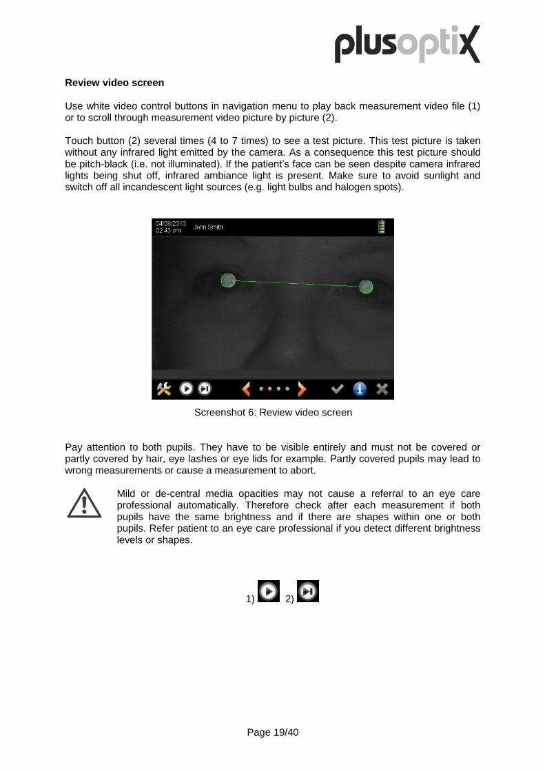
Review video screen Use white video control buttons in navigation menu to play back measurement video file (1) or to scroll through measurement video picture by picture (2). Touch button (2) several times (4 to 7 times) to see a test picture. This test picture is taken without any infrared light emitted by the camera. As a consequence this test picture should be pitch-black (i.e. not illuminated). If the patient’s face can be seen despite camera infrared lights being shut off, infrared ambiance light is present. Make sure to avoid sunlight and switch off all incandescent light sources (e.g. light bulbs and halogen spots).
Pay attention to both pupils. They have to be visible entirely and must not be covered or partly covered by hair, eye lashes or eye lids for example. Partly covered pupils may lead to wrong measurements or cause a measurement to abort.
Mild or de-central media opacities may not cause a referral to an eye care professional automatically. Therefore check after each measurement if both pupils have the same brightness and if there are shapes within one or both pupils. Refer patient to an eye care professional if you detect different brightness levels or shapes.
1) 2)
Screenshot 6: Review video screen
Page 20/40
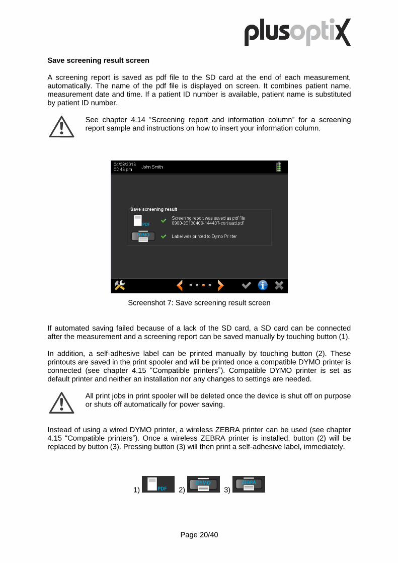
Save screening result screen A screening report is saved as pdf file to the SD card at the end of each measurement, automatically. The name of the pdf file is displayed on screen. It combines patient name, measurement date and time. If a patient ID number is available, patient name is substituted by patient ID number.
See chapter 4.14 “Screening report and information column” for a screening report sample and instructions on how to insert your information column.
If automated saving failed because of a lack of the SD card, a SD card can be connected after the measurement and a screening report can be saved manually by touching button (1). In addition, a self-adhesive label can be printed manually by touching button (2). These printouts are saved in the print spooler and will be printed once a compatible DYMO printer is connected (see chapter 4.15 “Compatible printers”). Compatible DYMO printer is set as default printer and neither an installation nor any changes to settings are needed.
All print jobs in print spooler will be deleted once the device is shut off on purpose or shuts off automatically for power saving.
Instead of using a wired DYMO printer, a wireless ZEBRA printer can be used (see chapter 4.15 “Compatible printers”). Once a wireless ZEBRA printer is installed, button (2) will be replaced by button (3). Pressing button (3) will then print a self-adhesive label, immediately.
1) 2) 3)
Screenshot 7: Save screening result screen

Page 21/40
Review database entries screen Each measurement of a patient is added to his record in the database, automatically. All previous measurements are displayed in chronological order. This listing of previous measurements shows at a glance if and how measurements and screening results changed over time.
Yellow entries indicate inconclusive measurements, green entries indicate „pass“ and red entries „refer“ screening results.
Single or multiple measurements can be deleted from the database. First, select a measurement to be deleted, by touching it on screen. The entry is highlighted with orange color and a delete symbol is displayed (1). Confirm selection by touching the delete symbol and a trash can (2) will be displayed instead. Then move on to the next measurements that need to be deleted. All measurements showing a trash can will be deleted once checkmark button (3) is touched. Press cancel button (4) to abort.
1) 2) 3) 4)
Screenshot 8: Review database entries screen

Page 22/40
3.6. Perform next measurement After reviewing measurement results orange shutter needs to be pressed in order to return to home screen. Returning to home screen previous patient is pre-selected (see button 1). This very same patient can be measured again by pressing the shutter a second time.
To measure the same patient over and over, touch screen doesn’t need to be touched. Hold on to the camera and keep pressing orange shutter. Every second push will start a new measurement.
To measure another patient, camera needs to be released and “next patient” button (2) on screen needs to be touched. This will open the enter patient data screen (see chapter 3.3 “Enter patient data”).
1) 2)
Screenshot 9: Home screen with last patient pre-selected

Page 23/40
4. Handling clues
Handling clues are sorted by keywords. Paragraphs can be read entirely or be consulted if relevant, only.
4.1. Holding camera and using neck strap Hold camera the same way as a tablet PC. Press orange shutter with the thumb of your right hand.
Adjust length of neck strap to put the weight of the camera onto your neck. In this case one hand can be used to hold camera off the body and the other hand to operate the touch screen.
Touch screen is mounted in a 45 degrees angle to camera axis. Tilt hand wrist down for proper alignment.
Picture 9: Holding the camera and pressing the shutter

Page 24/40
4.2. Retrieving, editing and deleting a patient from the database When entering patient data, a short list of matching entries is offered, automatically. Short lists are generated in any data field as soon as there are less than 5 matching entries left to choose from.
To select a patient right away, simply touch the matching patient data in the short list (1). The name (respectively ID number) of this patient will then be displayed in the title bar and a measurement can be started by pressing the orange shutter right away. Use backspace button (2) if there is a misspelling and add button (3) if the patient is new and needs to be added to the short list. If patient information within the database is wrong, it can be edited by touching the edit button (4). A patient can be deleted from the database (including all measurement results) by pressing the trash can button (5).
1) 2) 3) 4) 5)
Screenshot 10: Select patient from short list
Page 25/40
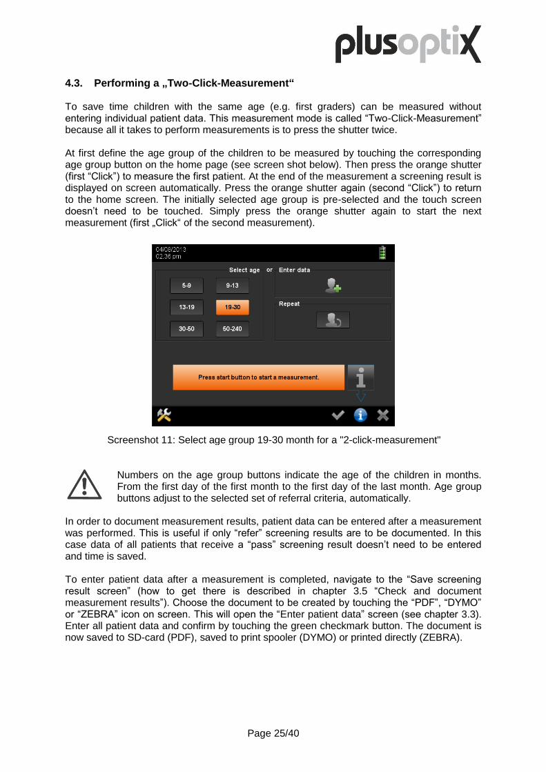
4.3. Performing a „Two-Click-Measurement“ To save time children with the same age (e.g. first graders) can be measured without entering individual patient data. This measurement mode is called “Two-Click-Measurement” because all it takes to perform measurements is to press the shutter twice. At first define the age group of the children to be measured by touching the corresponding age group button on the home page (see screen shot below). Then press the orange shutter (first “Click”) to measure the first patient. At the end of the measurement a screening result is displayed on screen automatically. Press the orange shutter again (second “Click”) to return to the home screen. The initially selected age group is pre-selected and the touch screen doesn’t need to be touched. Simply press the orange shutter again to start the next measurement (first „Click“ of the second measurement).
Numbers on the age group buttons indicate the age of the children in months. From the first day of the first month to the first day of the last month. Age group buttons adjust to the selected set of referral criteria, automatically.
In order to document measurement results, patient data can be entered after a measurement was performed. This is useful if only “refer” screening results are to be documented. In this case data of all patients that receive a “pass” screening result doesn’t need to be entered and time is saved. To enter patient data after a measurement is completed, navigate to the “Save screening result screen” (how to get there is described in chapter 3.5 “Check and document measurement results”). Choose the document to be created by touching the “PDF”, “DYMO” or “ZEBRA” icon on screen. This will open the “Enter patient data” screen (see chapter 3.3). Enter all patient data and confirm by touching the green checkmark button. The document is now saved to SD-card (PDF), saved to print spooler (DYMO) or printed directly (ZEBRA).
Screenshot 11: Select age group 19-30 month for a "2-click-measurement"

Page 26/40
4.4. Adjusting settings Settings can be used to customize the device. Touch the tool button (1) in the navigation bar to access the settings menu and touch the abort button in the navigation bar to exit settings menu (2).
Available settings are: - Customize basic settings (3) - Set date & time (4) - Choose language (5) - Set-up screen lock (6) - Configure software (7) - Choose referral criteria (8) - Activate WLAN (9) - Set-up EMR (10) - Export data (11) - Import data (12)
1) 2) 3) 4) 5) 6)
7) 8) 9) 10) 11) 12)
Screenshot 12: Settings menu

Page 27/40
4.5. Activating screen lock A screen lock can be activated to protect patient data that is saved within the device from unauthorized access. To activate screen lock it needs to be enabled and a PIN needs to be defined in settings, first. Touch screen lock icon in settings (1) to open screen lock set-up screen.
Once screen lock is enabled and a PIN is defined, it can be activated by touching the lock symbol button (1) in the navigation menu. Once screen is locked a 6 digit hexadecimal code has to be entered to unlock.
The lock symbol button in the navigation menu is displayed only if screen lock is activated in settings.
Screen lock is activated automatically only if device is switched off or switches off for power saving. The screen turning black for power saving will not activate screen lock.
Screen locks permanently if wrong PIN is entered three times! In this case a Master PIN is needed to unlock screen. You need to contact Plusoptix and provide your Master PIN number in order to obtain a matching Master PIN.
1)
Screenshot 13: Set-up screen lock

Page 28/40
4.6. Saving database backup, restoring database and generating reports All patient data is saved in the internal memory of the device. This patient database is used to retrieve previously entered patient data comfortably without the need to re-type all data. It can also be used to generate reports for analysis. To avoid a loss of patient data it’s recommended to save backup copies of patient database, regularly. Touch export data button (1) in settings to open the export data screen and connect an USB-Stick.
Please note that checkmark button will be inactive as long as no USB-Stick is connected (2).
To save a backup copy of the patient database don’t select any filters and touch the green checkmark button in the navigation menu (3). The entire database will be saved as db file to the USB-Stick. A backup copy of the patient database can be used to restore it. To restore a patient database connect an USB-Stick with the db file in its main directory. The patient database will be restored automatically.
When restoring a database, a backup copy of the existing database is automatically saved to the USB-Stick.
Select filters to generate a report and then touch green checkmark button (3) so save report as csv file. Csv files can be manipulated with all current spreadsheet software tools.
Selecting these filters will save a csv file including all patients who obtained a „refer“ screening result (5) at the screening location Berlin (10) and who were born (7) in between (9) March 1, 2008 and May 1, 2012. Touching button (4) will add all “pass” screening results and button (6) all inconclusive screening results. Touching button (8) will replace date of birth selection by date of screening and de-selecting button (9) will only include those screenings that took place March 1, 2008 precisely.
1) 2) 3) 4) 5) 6) 7) 8) 9) 10)
Screenshot 14: Generate a report
Page 29/40
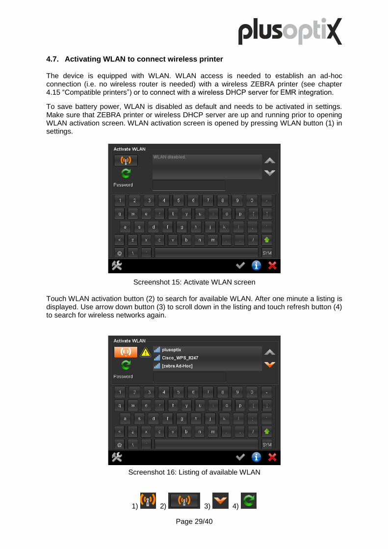
4.7. Activating WLAN to connect wireless printer The device is equipped with WLAN. WLAN access is needed to establish an ad-hoc connection (i.e. no wireless router is needed) with a wireless ZEBRA printer (see chapter 4.15 “Compatible printers”) or to connect with a wireless DHCP server for EMR integration.
To save battery power, WLAN is disabled as default and needs to be activated in settings. Make sure that ZEBRA printer or wireless DHCP server are up and running prior to opening WLAN activation screen. WLAN activation screen is opened by pressing WLAN button (1) in settings.
Touch WLAN activation button (2) to search for available WLAN. After one minute a listing is displayed. Use arrow down button (3) to scroll down in the listing and touch refresh button (4) to search for wireless networks again.
1) 2) 3) 4)
Screenshot 15: Activate WLAN screen
Screenshot 16: Listing of available WLAN

Page 30/40
A warning sign (1) indicates that no wireless network is selected. Choose the “zebra Ad-Hoc” network (2) by touching the listing. Entering a “password” is not necessary to set-up an ad-hoc connection to a Zebra printer.
Confirm “zebra Ad-Hoc” network selection with green checkmark button (3). This will close WLAN activation screen and settings main page will be displayed. Opening activate WLAN screen with WLAN already active will look as follows. A checkmark icon (3) instead of the warning sign (1) indicates an established connection. The network name is highlighted in orange color. Network IP address is displayed next to password (4).
1) 2) 3) 4)
Screenshot 17: Choosing Zebra printer
Screenshot 18: Reviewing network connection
Page 31/40
4.8. Importing patient data If a patient roster is available, patient data can be imported, but the existing patient roster needs to be adjusted. Necessary adjustments include conversion of patient roster in a csv file with semicolons as list separators and presenting patient data in the right sequence. Proceed as follows in order to use semicolons as list separators on your computer:
Open “Control Panel” on your computer (Windows operating system) Select “Clock, Language, and Region” followed by “Region and Laguage”. Choose “Formats” tab and click on “Additional setting”. Choose “Numbers” tab and go down to “List separator” Enter a semicolon (“;”) in the field for “List separator” Click on “Apply” followed by “OK”.
Your computer is now set up to write csv files in the right format. Now sort patient data in the right sequence:
Generate a report (see chapter 4.6 “Saving database backup, restoring database and generating reports”) and save it to your USB-Stick.
Connect this USB-Stick to your computer and open the report with your spreadsheet software (e.g. Microsoft Excel, Open Office Calc etc.).
Copy and paste your patient data into the corresponding data columns within this report file.
Delete all data rows that were exported initially (patient data that is already saved within the database can’t be imported a second time).
After adding all your patient data to the report file, save it to your USB-Stick. Make sure file format is csv and list separators are semicolons.
Connect your USB-Stick to Mobile Vision Screener plusoptiX S12 and choose „Import data“ in the settings menu (1).
A listing of all csv files that are available on your USB stick will be shown on screen. Choose the csv file to be imported and confirm by touching the green checkmark button in the navigation menu.
Prior to importing patient data the device checks if datasets are unique and if data entries are correct (e.g. no dates in name fields), automatically. However, interchanged data (e.g. first names instead of last names) can’t be detected automatically. Therefore check if patient data is presented in the right sequence and acknowledge patient data import by touching the green checkmark button in the navigation menu.
Imported patient data is always added to the existing patient database. Existing database entries are not deleted by importing patient data.
1)

Page 32/40
4.9. Touch screen is off (i.e. black) Touch screen illumination is switched off automatically to save power. Simply touch the screen to re-activate illumination. If the screen doesn’t illuminate after touching it, the device has switched off automatically. Press On/Off button to switch it on again.
In settings a time span until automatic power shut-off can be defined.
If the device doesn’t switch on after pressing the On/Off button, batteries are empty. Connect the medical power adapter and check if power is available (green LED on top of the medical power adapter is on). The device can be operated while batteries are charging. Simply switch it on by pressing the On/Off button with the medical power adapter connected.
4.10. Touch screen is inactive (i.e. buttons don’t work) Every time the touch screen is touched a little mouse pointer indicates where the touch was located. Check positioning of this mouse pointer if a touch button can’t be activated. Make sure the mouse pointer is superposing the touch button to be activated. Remember that touch buttons that are shown grayed out are in-active. A stylus can be used instead of a finger for greater precision in operating the touch screen.
4.11. A date of birth can’t be entered There are two reasons why a date of birth can’t be entered. First, date and time are not set correctly in settings. And second, the age of the child is younger than 5 Months or older than 300 Months.

Page 33/40
4.12. SD-Card and USB-Memory Interfaces Two storage media can be connected, a SD-Card and a USB-Stick. Pay attention to enter these storage media with connectors facing up (i.e. upside down)!
Some storage media may not be identified by the device. In this case use storage media from another manufacturer, instead. Not working storage media are neither a service nor a warranty claim!
All storage media have to be formatted in FAT 32 format. If a storage media with another format is entered the device will offer to format it in FAT 32.
If storage media is formatted, all data will be lost. No backup copy will be saved!
The advantage of a SD-Card is that it doesn’t stick out of the device body. Therefore it can remain within the device during measurements. All screening reports (see chapter 4.14 “Screening report and information column”) are saved onto a SD-Card exclusively. Database backup copies and reports are saved onto USB-Sticks exclusively (see chapter 4.6 Saving database backup, restoring database and generating reports). A USB-Stick is used to import an info column (see chapter 4.14 Screening report and information column), too. Info columns can be imported from USB-sticks, only.
All USB-Sticks poke out of the device body and should be connected temporarily, only. Remove USB-Sticks prior to performing measurements.
Instead of an USB-Stick, an USB keyboard or an USB mouse can be connected to the USB interface, alternatively (see chapter 4.16 “Using a stylus, mouse or keyboard”).
4.13. Micro-USB Interface The device has a micro USB interface. This interface is used in production and for service and warranty inspections. During operation this micro USB interface is not in use.
Don’t connect any external devices to the micro USB interface to avoid damaging the device!

Page 34/40
4.14. Screening report and information column A screening report can be used to inform parents and an eye care professional in case of a referral. A screening report is saved as pdf file to the SD card at the end of each measurement, automatically.
Picture 10: Screening report
The column to the left is called info column. This info column can be designed freely and adjusted anytime. Generate your graphic file with 583 x 3,300 (width x hight) pixels in png format. Name your graphic file “info.png” and save it to the main directory of your USB-Stick. Connect your USB-Stick to the running device and your graphic file will be uploaded automatically.

Page 35/40
4.15. Compatible printers A self-adhesive label can be printed if a paper record of the measurement is needed on site. Information provided on a self-adhesive label is:
Default printer is a DYMO LabelWriter 450 (see: www.dymo.com). In order to generate a printout, this printer needs to be connected to the Plusoptix device with an USB cable and the printer needs to be connected to the mains for power supply. To use a DYMO printer, the following genuine Dymo printing labels are needed:
LabelWriter Labels White 3.5” Disk 2-1/8” x 2-3/4”; 320 labels per roll These labels can be ordered online from DYMO (search at www.dymo.com for SKU # 30324 or at www.dymo.de for SKU # S0722440). Optional printer is a ZEBRA QLn 220 (see: zebra.com). This printer has a WLAN interface and is battery powered. A wireless “ad-hoc” connection to the Plusoptix device can be established (i.e. a wireless router is not needed). To use a Zebra printer, the following genuine Zebra printing labels are needed:
Label, Paper, 50.8 x 38.1 mm, Direct Thermal, Z-Select 2000D, 250 labels per roll These labels can be ordered from ZEBRA (search at www.zebra.com for part # 3003060). Please refer to chapter 4.7 “Activating WLAN to connect wireless printer” for instructions on how to replace default DYMO printer with optional ZEBRA printer.
Other printers are not compatible and it’s impossible to install aftermarket printer driver software. Attempting to install printer driver software will end medical device registration as well as warranty coverage.
John Smith, *10/07/2010 OD Refer OS +0,75 dpt Sphere +0,25 dpt -0,75 dpt Cylinder -2,25 dpt 176° Axis 87° 5,8 mm Ø pupil 4,5 mm Interpupillary distance 56 mm Gaze asymmetry 7,6 ° ROC 3, Version 6.0.1.0 05/01/2013
www.plusoptix.com Referral criteria used
Readings right eye
Patient name or ID
Measurement date
Readings left eye
Date of birth
Screening result

Page 36/40
4.16. Using a stylus, mouse or keyboard A stylus, USB-mouse or USB-keyboard can be used to operate the touch screen more comfortably. Mouse or keyboard can be wired or wireless. Simply connect the USB connector or USB receiver to the in-built USB port of the device.
USB port within the device is positioned upside down, i.e. USB connector or USB receiver of mouse/keyboard need to be turned upside down prior to connecting them to the device.
If an USB-mouse or USB-keyboard is not working, check if batteries are inserted, first. Make sure mouse or keyboard are switched on. Try an USB-mouse or USB-keyboard of another manufacturer (Logitech, Microsoft) in case mouse or keyboard still don’t work.
Not working USB-mice or USB-keyboards are neither a service nor a warranty claim!
4.17. EMR integration The device is equipped with a WLAN interface and can be connected to an Electronic Medical Record (EMR) system. This integration allows to import patient data and to export readings wirelessly. There is a separate EMR integration manual available. Please contact Plusoptix or your distributor in case you want to connect your device to your EMR system.
Please note that EMR integration can’t be used to connect the device to network printers! EMR integration exchanges data electronically, only.

Page 37/40
4.18. Aborted measurements – What is the meaning of error messages? A measurement is aborted if there is too much infrared ambiance light. The corresponding error message reads:
This error is typically caused by sunlight in the examination room. But infrared ambiance light can be emitted by incandescent light sources (e.g. light bulbs and halogen spots), too. To avoid this error, shade examination room and switch all heat emitting light sources off. A measurement is aborted if no pupils are detected within 20 seconds after pressing the orange color shutter. The corresponding error message reads:
There are three causes for this error: pupils themselves, measurement distance and eye/device alignment. Both pupil diameters need to be in between 4 and 8 mm and pupils must not be covered by eye lids, eye lashes or long hair. Check if both pupils are displayed with a round shape on screen. Measurement distance needs to be in between 95 and 105 cm (i.e. 3.1 and 3.5 feet). Check if camera picture is displayed pin sharp on screen (i.e. each single hair of eye lashes is displayed). Both, eyes and camera need to be aligned with each other. A patient needs to focus the nose of the smiley face and the camera needs to capture a picture of both eyes. Check if green dots are plotted in both gaze charts.

Page 38/40
5. Maintenance, calibration, service and warranty
Mobile Vision Screener plusoptiX S12 is an opto electronic measurement device. Mechanical construction and mode of operation can be compared to a video camera. If you treat your Mobile Vision Screener plusoptiX S12 as thoughtful as your personal video camera, it will be operational for many years. Maintenance and calibration The device is maintenance and calibration free. Put it in its carrying case if not in use. This will protect it from dirt and damage. Only use a moist microfiber cloth to clean the device. Service If the device is not working flawlessly, read chapter 4 “Handling clues“, first and then contact your authorized Plusoptix dealer for support. Warranty The device comes with a 12 Month warranty from the date of purchase. A warranty extension is available. Please contact Plusoptix or your authorized Plusoptix dealer if you want to purchase a warranty extension. Warranty expires in case of external damage, improper use, wrong cleaning or transportation without carrying case. Warranty expires if device was opened, too. Please note that warranty does not cover rechargeable batteries, SD card and auxiliaries such as printers, keyboard, mice etc. Sending a device in For service or warranty repair we kindly ask you to put your device in its carrying case into a covering box and to ship it at your expenses to our nearest service center. We will return it to you at our expenses. Shipping addresses of our service centers are in Europe: Plusoptix GmbH Neumeyerstrasse 46 90411 Nuremberg Germany Tel: +49-911-59 83 99-10
in North and South America: Plusoptix, Inc. 2850 Paces Ferry Road Suite 440 Atlanta, GA 30339 USA Tel: +1-800-488-6436

Page 39/40
6. Technical specifications
6.1. Measurements
Metered value Measurement range and tolerance
Sphere -7 to +5 dpt in 0,25 dpt increments ± 0,25 dpt
Cylinder -7 to +5 dpt in 0,25 dpt increments ± 0,25 dpt
Axis 1 to 180° in 1° increments ± 15°
Spherical equivalent -7 to +5 dpt in 0,25 dpt increments ± 0,25 dpt
Pupil diameter 4 to 8 mm in 0,1 mm increments ± 10%
Gaze asymmetry in 0,1° increments ± 5°
Inter pupillary distance in 0,1 mm increments ± 10%
6.2. Interfaces and standards
Interfaces USB and Micro USB
SD-Card
WLAN and Bluetooth
Monitor Screen size 5,7“ (640 x 480 Pixel); Ratio 4:3
Touch sensor capacitive
Standard EN 60601-1
6.3. Power supply and rechargeable batteries Only use medical power adapter type MES30B-3P1J which is included in the delivery.
Medical power adapter (Type MES30B-3P1J)
Input 110 to 240 VAC (50 to 60 Hz), 0,8 A
Output 12 VDC, 2,5A
Rechargeable batteries (Sanyo HR-3UTGA 1,2V)
Type / Size Nickel metal hydride NiMH / AA HR6
Wattage / Number 1900 mAh / 6 pieces
6.4. Ambient conditions for operation and storage The device can be stored in its carrying case. Don’t store carrying case close to heat sources (radiators, heater blowers, etc.). If device is taken out of carrying case, don’t place it in direct sunlight.
Storage Temperature 0 to +50°C
Humidity 10 to 80% noncondensing
Operation Temperature +10 to +50°C
Humidity 20 to 80% noncondensing
6.5. Size and weight with and without carrying case
Device without case Size 250 x 150 x 140 mm (10 x 6 x 5½”)
Weight 1,1 Kg (38.8 oz)
Device with case Size 430 x 185 x 370 mm (17 x 7¼ x 14½”)
Weight 3,4 Kg (119.9 oz)

Page 40/40
6.6. Guidance and manufacturer´s declaration – electromagnetic emissions/ immunity
The device is intended for use in electromagnetic environments as specified below. Owner and user of the device are responsible that these assure that it is in such an environment. Emissions Test Compliance Electromagnetic environment - Guidance
RF Emission CISPR 11 Group 1 RF emissions are very low and are not likely to cause any interference in nearby electronic equipment.
RF Emission CISPR 11 Class B The device is suitable for use in all establishments, including domestic establishments and those directly connected to the public low voltage power supply network that supplies buildings used for domestic purposes.
Harmonic Emissions IEC 61000-3-2
Class B
Voltage fluctuations / flicker emissions IEC 61000-3-3
Class B
Immunity test IEC 60601 test level Compliance level Electromagnetic environment - Guidance
ESD IEC 61000-4-2 ± 6 kV contact ± 8 kV air
± 6 kV contact ± 8 kV air
Floors should be wood, concrete or ceramic tile. If floors are covered with synthetic material the relative humidity should be at least 30 %.
Electric fast transient/burst IEC 61000-4-4
± 2 kV for power supply lines
± 2 kV for power supply lines
Mains power supply should be that of a typical commercial or hospital environment.
Surge IEC 61000-4-5
± 1 kV differential mode ± 2 kV common mode
± 1 kV differential mode ± 2 kV common mode
Mains power supply should be that of a typical commercial or hospital environment.
Voltage Dips, short interruptions and voltage variations on power supply input lines IEC 61000-4-11
0% 0.5 periods 0° 40% 5 periods 0° 70% 25 periods 0° 0% 250 periods 0°
0% 0.5 periods 0° 40% 5 periods 0° 70% 25 periods 0° 0% 250 periods 0°
Mains power supply should be that of a typical commercial or hospital environment.
Power Frequency (50/60 Hz) magnetic field IEC 61000-4-8
3 A/m 3 A/m
Power frequency magnetic fields should be at levels characteristic of a typical location in a typical commercial or hospital environment.