modal analysis of fixed-fixed beam siti...
TRANSCRIPT

MODAL ANALYSIS OF FIXED-FIXED BEAM
SITI SARAH BINTI AHMAD
Report submitted in partial fulfilment of the requirementsfor the award of the degree of
Bachelor of Mechanical Engineering
Faculty of Mechanical EngineeringUNIVERSITI MALAYSIA PAHANG
NOVEMBER 2010
iii
SUPERVISOR’S DECLARATION
I hereby declare that I have checked this project report and in my opinion, this project is
adequate in terms of scope and quality for the award of the degree of Bachelor of
Mechanical Engineering
Signature :………………………
Name of Supervisor : Mr. Mohd Firdaus Hassan
Position : Supervisor
Date : 6 Disember 2010

iii
STUDENT’S DECLARATION
I hereby declare that the work in this project is my own except for quotations and
summaries which have been duly acknowledged. The project has not been accepted for
any degree and is not concurrently submitted in candidature of any other degree.
Signature : .....................................
Name : Siti Sarah Binti Ahmad
ID Number : MA08020
Date : 6 Disember 2010

v
DEDICATION
This report is dedicated Allah whose guidance, help and grace was instrumental in making this humble work a reality. To my beloved parents, Mr. Ahmad Bin Omarand Mrs. Che Siah Binti Othman, family and friends, without whom and his or her lifetime efforts, my pursuit of higher education would not have been possible and I would not have had the chance to study for a mechanical course.
Also to my supervisor, Mr. Firdaus Hassan and to the entire lecturers without whose wise suggestions, helpful guidance and direct assistance, it could have neither got off the ground nor ever been completed.

vi
ACKNOWLEDGEMENTS
AssalamualaikumWarahmatullahWabarakatuh….
First of all, thanks to Allah The Mighty because giving me blessing health and ideas to finish my project successfully. Hopefully, Allah always bless me in the future.
This project was conducted under the supervision of En. Firdaus Hassan in the University Malaysia Pahang (UMP). I am very grateful to him for his patience and hisconstructive comments that enriched this project. His time and efforts have been a great contribution during the preparation of this thesis that cannot be forgotten forever.
I would like to thanks to the lecturers and technicians at the Faculty of Mechanical for their valuable comments and sharing their time and knowledge on this project during my last trip to submit the project. I also gratefully acknowledge the assistance of everybody who helped in the execution of this project in UMP.
I also thank to Mechanical students for their friendship and help when thinking through problems and for sharing their knowledge. Finally, I thank my family for their continuous support and confidence in my efforts.

vii
ABSTRACT
This project work describes in detail, includes a brief description of the Modal Analysis of Fixed-Fixed Beam, supplemented by a good number of necessary and descriptive drawings which makes this project report very easy to understand. The objective of this project is to determine the dynamic behaviour or modal characteristics of fixed-fixed beam using modal analysis. There are two methods used in this project which are simulation by using Algor software and experimental by using Hammer Excitation. In addition to these, the report also contains the details regarding the different type of natural frequencies and mode shapes. In simulation, the natural frequency based on the mesh size starting from 100%,90%,80% and 70%. The result obtained from the minimum value of natural frequency lies between range 113.1345Hz and 160.0712Hz which refer to the Mode 1. Mode 5 of the maximum value of natural frequency is in the range of 640.0954Hz until 713.1101Hz. By comparing with the experimental results, the average of first point is 163Hz and the fifth point is 740.5Hz. Both results show that there are no much different as the errors are between 0.13% until 2.45%. The result from both method can be accepted regarding to the objective achieved.

viii
ABSTRAK
Projek ini menjelaskan secara terperinci, termasuk penerangan singkat mengenai Modal Analisa Pada Rasuk Terikat Dikedua-dua Hujungnya, telah dilengkapkan dengangambar yang diperlukan dan butiran yang membuat laporan projek ini mudah difahami. Tujuan projek ini adalah untuk menentukan perilaku dinamik atau ciri-ciri modal padarasuk terikat dikedua-dua hujung menggunakan analisa modal. Terdapat dua kaedahyang digunakan dalam projek ini iaitu simulasi dengan menggunakan perisian Algordan uji kaji makmal dengan menggunakan Tukul Pengukuran. Selain itu, laporan inijuga mengandungi butiran mengenai pelbagai jenis frekuensi semulajadi dan bentukmod struktur. Dalam simulasi, frekuensi semulajadi berdasarkan saiz mesh bermuladaripada 100%, 90%, 80% dan 70%. Keputusan yang diperolehi daripada nilai minimum frekuensi semulajadi terletak di antara 113.1345Hz dan 160.0712Hz yang merujuk pada Bentuk Mod 1. Bentuk Mod 5 dari nilai maksimum frekuensi semulajadiadalah pada julat 640.0954Hz sehingga 713.1101Hz. Dibandingkan dengan hasil ujikaji, julat purata titik pertama adalah 163Hz dan titik kelima 740.5Hz. Kedua-dua keputusanmenunjukkan bahawa tiada perbezaan ketara diantara kerana ralat adalah di antara 0.13% hingga 2.45%. Hasil dari kedua-dua kaedah boleh digunapakai sehubungandengan objektif yang telah dicapai.

ix
TABLE OF CONTENTS
Page
SUPERVISOR’S DECLARATION ii
STUDENT’S DECLARATION iii
DEDICATION iv
ACKNOWLEDGEMENTS vi
ABSTRACT vii
ABSTRAK viii
TABLE OF CONTENTS ix
LIST OF TABLES xii
LIST OF FIGURES xiii
LIST OF ABBREVIATIONS xv
CHAPTER 1 INTRODUCTION
1.1 Introduction and Project Background 1
1.2 Problem Statements 3
1.3 Project Objectives 3
1.4 Project Scopes 4
CHAPTER 2 LITERATURE REVIEW
2.1 Introduction 5
2.2 Modal Analysis 6
2.3 Historical On Modal Analysis 7
2.4 Example of Modal Analysis
2.4.1 Modal Analysis of a Complete 18m-C Sailplane 8 2.4.2 Modal Analysis of Two Wheeled Vehicle 11 2.4.3 Modal Analysis of a Crack Beam 14
2.5 Experimental Modal Analysis 16
2.5.1 History of Experimental Modal Analysis 16 2.5.2 Frequency Response Function Measurement 17
x
2.6 The Important of Modal Analysis 18
2.7 Mode Shape 18
2.8 Natural Frequency 19
CHAPTER 3 METHODOLOGY
3.1 Introduction 22
3.2 Flow Chart 23
3.3 Materials Selection 24
3.3.1 Mild Steel (AISI 1080) 25 3.3.2 Brass 29
3.4 Modelling
3.4.1 Solidwork Software 29
3.5 Finite Element Method
3.5.1 Algor Software 30 3.5.2 Simulation in Algor 31
3.6 Experimental Modal Analysis
3.6.1 Impact Testing 32 3.6.2 PULSE Labsop Software 33 3.6.3 Performing Experimental Modal Analysis 34
CHAPTER 4 RESULT AND DISCUSSION
4.1 Introduction 36
4.2 Algor Simulation Results 37
4.2.1 Mode Shape 38
4.3 Experimental Results 41
4.4 Discussions 44
xi
CHAPTER 5 RECOMMENDATIONS AND CONCLUSION
5.1 Conclusion 46
5.2 Recommendations 47
REFERENCES 48
APPENDICES
A Technical Drawing 50
B 3D Solid Drawing 51
C FFT and Coherence Graph 53
xii
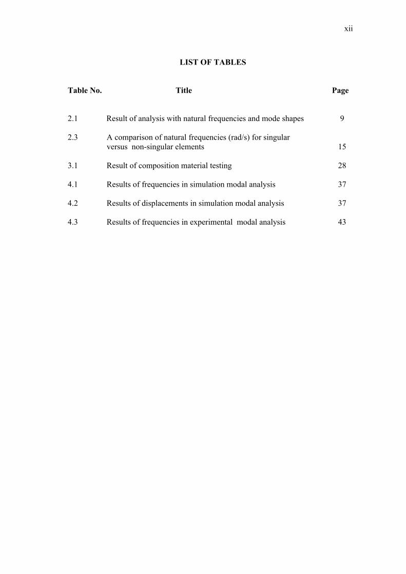
LIST OF TABLES
Table No. Title Page
2.1 Result of analysis with natural frequencies and mode shapes 9
2.3 A comparison of natural frequencies (rad/s) for singular versus non-singular elements 15
3.1 Result of composition material testing 28
4.1 Results of frequencies in simulation modal analysis 37
4.2 Results of displacements in simulation modal analysis 37
4.3 Results of frequencies in experimental modal analysis 43
xiii
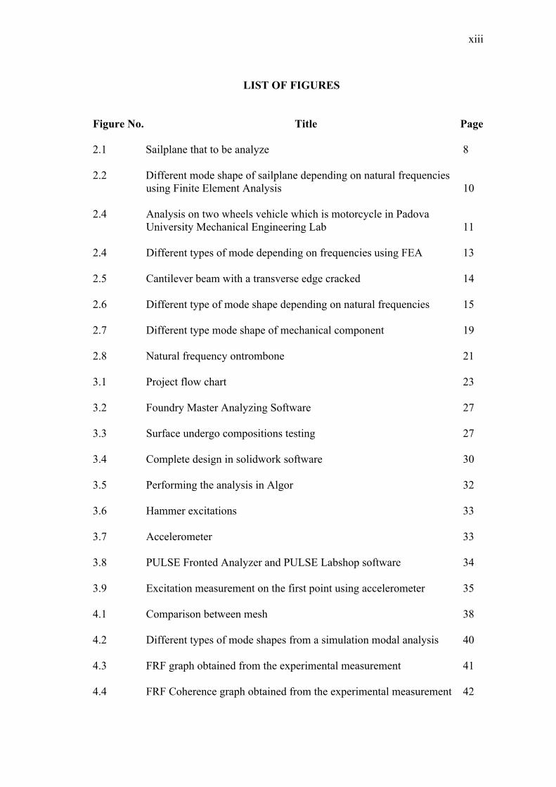
LIST OF FIGURES
Figure No. Title Page
2.1 Sailplane that to be analyze 8
2.2 Different mode shape of sailplane depending on natural frequencies using Finite Element Analysis 10
2.4 Analysis on two wheels vehicle which is motorcycle in Padova University Mechanical Engineering Lab 11
2.4 Different types of mode depending on frequencies using FEA 13
2.5 Cantilever beam with a transverse edge cracked 14
2.6 Different type of mode shape depending on natural frequencies 15
2.7 Different type mode shape of mechanical component 19
2.8 Natural frequency ontrombone 21
3.1 Project flow chart 23
3.2 Foundry Master Analyzing Software 27
3.3 Surface undergo compositions testing 27
3.4 Complete design in solidwork software 30
3.5 Performing the analysis in Algor 32
3.6 Hammer excitations 33
3.7 Accelerometer 33
3.8 PULSE Fronted Analyzer and PULSE Labshop software 34
3.9 Excitation measurement on the first point using accelerometer 35
4.1 Comparison between mesh 38
4.2 Different types of mode shapes from a simulation modal analysis 40
4.3 FRF graph obtained from the experimental measurement 41
4.4 FRF Coherence graph obtained from the experimental measurement 42

xiv
4.5 Results of five point of frequencies from the experimental 43
4.6 Comparison of two result method 45
4.7 Four types of view in one complete drawing 50
4.8 Different types of View 52
4.9 Different types of FFT and Coherence graph depend on the points 54
LIST OF SYMBOLS
xv
/ Radiant per second
°C Degree Celcius
Heat capacity
Melting temperature
kg/ Kilogram per meter cubic
Thermal conductivity
Millimetres squared
Metre square
N Newton
≤ Less than
≥ More than
CHAPTER 1
INTRODUCTION
1.1 INTRODUCTION AND PROJECT BACKGROUND
Beams are used all around us in many mechanical and structural engineering
applications. They are commonly used to create a foundation or internal support for a
larger structure, such as a building or a bridge. Beam analysis requires a combination
of mechanical engineering, design principles, and material properties. The process
typically involves factors including the beam shape, the material, and the design of
the joints to allow one beam to be mechanically connected to other structural
members.
The construction of a beam will influence its bending and deflection while
under load. The deflection of a beam depends on its length, how it is supported, its
cross-sectional shape, the material, and where the deflecting force is applied. Beam
are classified according to the way in which they are supported. Several types of
beams frequently used in the construction field today are simply supported,
overhanging, cantilever, continuous, fixed and hinged-hinged beam (Ferdinand et
al.,2006). In this case, fixed-fixed beam is selected to be design in the CAD software
which is Solidwork and to be analyze in the concept of modal analysis using Finite
Element Analysis (FEA) software.
2
Computer aided design which known as CAD is the use of computer
technology for the design of objects, real or virtual. CAD often involves more than
just shapes. As in the manual drafting of technical and engineering drawings, the
output of CAD often must convey symbolic information such as materials, processes,
dimensions, and tolerances according to application-specific conventions. CAD may
be used to design curves and figures in two-dimensional 2D space or curves,
surfaces, and solids in three-dimensional 3D objects. CAD is an important industrial
art extensively used in many applications including automotive, shipbuilding and
aerospace industries, industrial and architectural design, prosthetics and many more.
FEA is stand for finite element analysis is an engineering software that is
designed to accept input data and determine a beam design to meet the performance
criteria. The FEA is also to be known as the finite element method which is FEM
analysis is a numerical technique for finding approximate solutions of partial
differential equations as well as of integral equations. The solution approach is based
either on eliminating the differential equation completely for steady state problems,
or rendering the equation into an approximating system of ordinary differential
equations, which are then numerically integrated using standard techniques such as
Euler's method and Runge-Kutta.
These programs completed with a mathematical analysis of the structure such
as beam stresses and deflection, and also create diagrams showing stress distributions
within the beam under various loading conditions. By using this software, we can
analyze the beam to get the frequency and mode shape. For the design engineers,
mode shapes are useful because they represent the shape that will vibrate in free motion.
This two things is important to helps the engineer design the beam that safe to be
used. This analysis also is to determine the dynamic behavior of the structure. The
dynamic behavior is the behavior of a system or component under actual operating
conditions such as vibrations.
3
The analysis including the beam shape and the design of the points to allow
one beam to be mechanically connected to other structural members such as hinges.
For this project, the title is Modal Analysis of Fixed-Fixed Beam, it required to know
and do an analysis using Finite Element Analysis (FEM) by using Algor software
and also Solidwork to make a design. It is also need the welding skill to fabricate a
simple model of the beam.
Overall, this project involved the designing and fabricating of the beam
model and the test required to be conducted and to verify the design project. After
finishing and completing the whole project, student can get more skills in designing,
fabricating and simulating using Algor and Solidwork software. To complete this
project, first student need to improve the skill when using the related software and
also in operating and handling the welding machine so that it can help the student
better.
1.1 PROBLEM STATEMENTS
In this new era, the world now had become unstable because of many factors.
There are a lot of cases that we heard recently which happened because of mother
nature that caused many structures cracked, failed or collapsed such as building and
bridge, for example Tacoma Bridge in London. From this problems comes an idea to
make an analysis to one of the structure like beam to understand it behavior so that it
hard to be fail. The application of simulation software such as Algor can help us
understand better by determining the mode shape and frequency.
1.2 PROJECT OBJECTIVE
The main objective for this research is to determine the dynamic behavior or
modal characteristics of fixed-fixed beam using modal analysis.

4
1.3 PROJECT SCOPES
The scopes for this project are stated as per below :
1. Selection of an available beam and type of joint will be used in this
project.
2. Determination of mechanical properties of the beam such as Young`s
Modulus, density and poison ratio.
3. Fabrication of test rig for modal analysis testing.
4. Modeling a fixed-fixed beam in CAD software.
5. Performing a dynamic analysis in Finite Element Analysis(FEA)
software in order to obtain its modal parameter such as natural
frequency and mode shape.
6. Continuing modal analysis testing using impact hammer test
equipment.
7. Comparison between simulation and experimental.

CHAPTER 2
LITERATURE REVIEW
2.1 INTRODUCTION
Every structure that had been invented by the engineer had their own
specifications that has to be followed. Beam also does not exceptional. There are a
lot of types of beams that we can found in some of the structure depending on the use
of the structure itself such as cantilever beam, fixed beam, continuous beam, simply
supported beam and there are some more types that can be recognized. For this case,
the beam that to be analyze is fixed-fixed beam using modal analysis. Fixed-fixed is
a beam that is supported at both free ends and is restrained against rotation and
vertical movement.
For example, the beam that fixed at the ends so that it cannot tilt up when the
force is loaded. It is well known that structures can resonate where the small forces
can result in important deformation and possibly can damage the structure. This
beam also known as built-in beam. In this case, used the hinge of a door to make an
illustration to a real situation. The hinged will be fixed welding to the both ends of
the beam.
6
The Tacoma Narrows bridge disaster is a typical example of these phenomena. On
November 7, 1940, the Tacoma Narrows suspension bridge collapsed due to wind-
induced vibration. It is basically about wind load that acting on the structure
(Kijewski and Kareem, 1998). The bridge had only been open for traffic a few
months. To overcome this problem so that it will never happen again, today to better
understand any structural vibration problem, the resonant frequencies of a structure
need to be identified and quantified. One of the solution by using modal analysis.
2.2 MODAL ANALYSIS
The majority of structures can be made to resonate likes the structures will
vibrate in the excessive oscillatory motion. Resonant vibration is mainly caused by
an interaction between the inertial and elastic properties of the materials within a
structure. The contributing factor to many of the vibration and noise related problems
that occur in structures and operating machinery is called resonance. Resonant
frequencies of a structure need to be identified and quantified if we want to
understand better of the vibrations. Today, modal analysis is one of the procedures of
finding the modes of vibration of a machine or structure. In the general meaning,
modal analysis is a process of determining the existent dynamic characteristic of a
system in form of natural frequency, damping factors and mode shapes and from this
we can generate a mathematical model for its dynamic behavior (Jimin, 1998).
In the simple words, it is the study of the natural characteristics of structures.
We can design the structural noise and vibration applications if we understand better
on natural frequency and mode shape. A mode shape is a specific pattern of vibration
executed by a mechanical system at a specific frequency. Different mode shapes will
be associated with different frequencies. To determine the vibration of a system, the
mode shape is multiplied by a function that varies with time, thus the mode shape
always describes the curvature of vibration at all points in time but the magnitude of
the curvature will change. The mode shape is dependent on the shape of the surface
as well as the boundary conditions of that surface (Blevins and Robert, 1995).
7
Modal analysis also related to the response. The response of the structure is
different at each of the different natural frequencies. These deformation patterns are
called mode shapes. Now we can better understand what modal analysis is all about
which is it is the study of the natural characteristics of structures. The existent of
modal analysis is to help design all types of structures including automotive
structures, aircraft structures, spacecraft, computers, tennis rackets, golf clubs and
more.
2.3 HISTORICAL ON MODAL ANALYSIS
The history of experimental modal analysis during the 1970s is mostly found
in papers presented like Sound and Vibration. Examples are the original paper
presenting the Least Squares Complex Exponential algorithm in the SAE
Transactions and the complete discussion of impact testing in Sound and Vibration.
During one point in the late 1970s, an animated mode shape that presented part of a
car commercial on television.
Nevertheless, there was a need for a conference that would focus on this
important experimental aspect of structural dynamics. In 1979, two engineers from
General Electric, Peter Juhl and Dick DeMichele, who tried to convince all of the
boards that United College should start such an international conference. Pete and
Dick ultimately received the same response from a number of vendors and
organizations and proceeded, with the assistance of Union College, of organizing the
first International Modal analysis Conference called IMAC in 1982. From there, the
rest is history and the documentation of the next 25 years is a matter of public record.
The Conference took on a professional society affiliation with the Society of
Experimental Mechanics in 1988. Since 1982, the history of experimental modal
analysis is well documented from the year-to-year contributions to the IMAC
Proceedings. In recent years, the tradition of cooperating with industry and
promoting education, have also staffed a Technology Center Booth at a number of
international and professional society conferences, beginning with the IMAC
Conference.
8
2.4 EXAMPLES OF MODAL ANALYSIS
2.4.1 Modal Analysis of a Complete 18m-class Sailplane
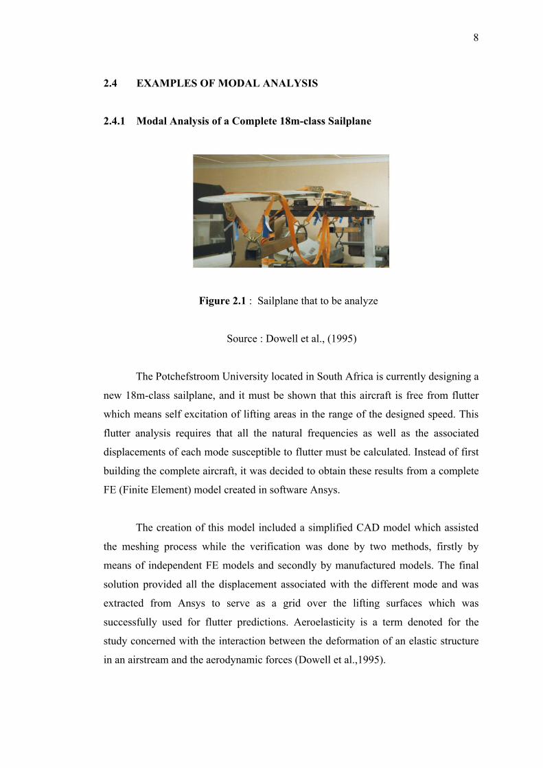
Figure 2.1 : Sailplane that to be analyze
Source : Dowell et al., (1995)
The Potchefstroom University located in South Africa is currently designing a
new 18m-class sailplane, and it must be shown that this aircraft is free from flutter
which means self excitation of lifting areas in the range of the designed speed. This
flutter analysis requires that all the natural frequencies as well as the associated
displacements of each mode susceptible to flutter must be calculated. Instead of first
building the complete aircraft, it was decided to obtain these results from a complete
FE (Finite Element) model created in software Ansys.
The creation of this model included a simplified CAD model which assisted
the meshing process while the verification was done by two methods, firstly by
means of independent FE models and secondly by manufactured models. The final
solution provided all the displacement associated with the different mode and was
extracted from Ansys to serve as a grid over the lifting surfaces which was
successfully used for flutter predictions. Aeroelasticity is a term denoted for the
study concerned with the interaction between the deformation of an elastic structure
in an airstream and the aerodynamic forces (Dowell et al.,1995).
9
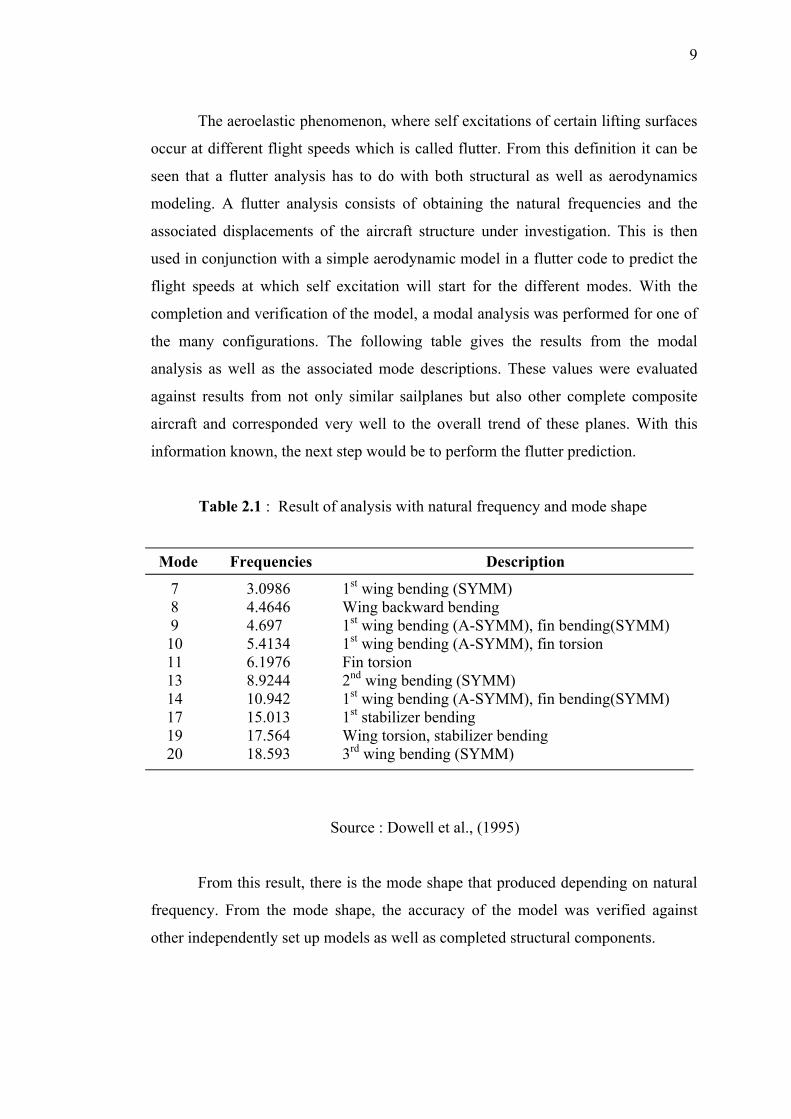
The aeroelastic phenomenon, where self excitations of certain lifting surfaces
occur at different flight speeds which is called flutter. From this definition it can be
seen that a flutter analysis has to do with both structural as well as aerodynamics
modeling. A flutter analysis consists of obtaining the natural frequencies and the
associated displacements of the aircraft structure under investigation. This is then
used in conjunction with a simple aerodynamic model in a flutter code to predict the
flight speeds at which self excitation will start for the different modes. With the
completion and verification of the model, a modal analysis was performed for one of
the many configurations. The following table gives the results from the modal
analysis as well as the associated mode descriptions. These values were evaluated
against results from not only similar sailplanes but also other complete composite
aircraft and corresponded very well to the overall trend of these planes. With this
information known, the next step would be to perform the flutter prediction.
Table 2.1 : Result of analysis with natural frequency and mode shape
Mode Frequencies Description
7 3.0986 1st wing bending (SYMM) 8 4.4646 Wing backward bending 9 4.697 1st wing bending (A-SYMM), fin bending(SYMM) 10 5.4134 1st wing bending (A-SYMM), fin torsion 11 6.1976 Fin torsion 13 8.9244 2nd wing bending (SYMM) 14 10.942 1st wing bending (A-SYMM), fin bending(SYMM) 17 15.013 1st stabilizer bending 19 17.564 Wing torsion, stabilizer bending 20 18.593 3rd wing bending (SYMM)
Source : Dowell et al., (1995)
From this result, there is the mode shape that produced depending on natural
frequency. From the mode shape, the accuracy of the model was verified against
other independently set up models as well as completed structural components.
10
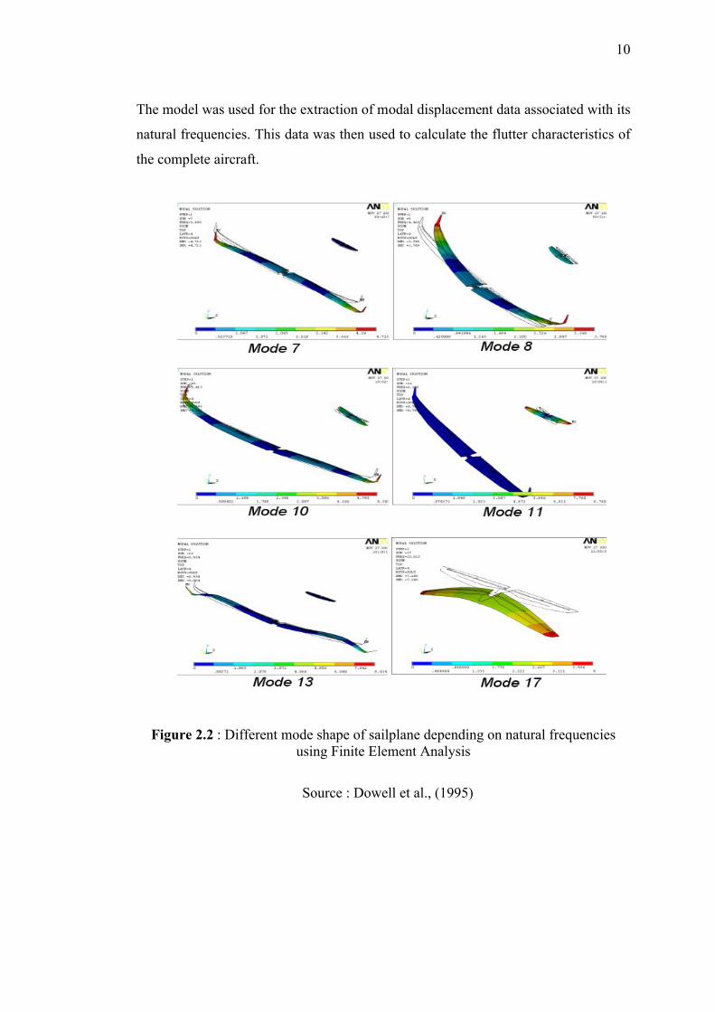
The model was used for the extraction of modal displacement data associated with its
natural frequencies. This data was then used to calculate the flutter characteristics of
the complete aircraft.
Figure 2.2 : Different mode shape of sailplane depending on natural frequenciesusing Finite Element Analysis
Source : Dowell et al., (1995)