modbus driver for idaq · modbus for idaq is a component for idaq that reads and writes data with...
TRANSCRIPT

ModBus Driver for
iDaq
User guide
March 2020
Rev 2.0

ModBus iDaq Component – User Guide
2

TOOLS for SMART MINDS
3
Worldwide technical support and product information:
www.toolsforsmartminds.com
TOOLS for SMART MINDS Corporate headquarter
Via Padania, 16 Castel Mella 25030 Brescia (Italy)
Copyright © 2020 TOOLS for SMART MINDS. All rights reserved.
ModBus iDaq Component – User Guide
4
SUMMARY Overview ............................................................................................................................................................................. 5
Introduction ........................................................................................................................................................................ 5
Requirements ..................................................................................................................................................................... 6
Minimum hardware requirements ............................................................................................................................. 6
Minimum software requirements .............................................................................................................................. 6
Installation .......................................................................................................................................................................... 7
Getting started with ModBus devices ................................................................................................................................ 9
Adding a ModBus device to the list of active devices ..................................................................................................... 9
TCP(Ethernet) communication ................................................................................................................................. 11
Serial communication ............................................................................................................................................... 11
ModBus capabilities ...................................................................................................................................................... 13
General Capability Settings ....................................................................................................................................... 14
Handshake Settings .................................................................................................................................................. 15
Text Acquisition/Generation Configuration .............................................................................................................. 20
Reboot Settings ............................................................................................................................................................. 22
Advanced Settings ........................................................................................................................................................ 23
Start-Up Channel Configuration ............................................................................................................................... 24
ModBus channel management ..................................................................................................................................... 26
Channel creation ....................................................................................................................................................... 27
Further details .................................................................................................................................................................. 41

TOOLS for SMART MINDS
5
OVERVIEW iDaq supports installation of additional components to extend capabilities and features of
iDaq itself. With additional components, new types of acquisition devices, new signals
processing features, and other kinds of functionalities can be added to iDaq.
ModBus Driver is a component for iDaq that provide ModBus communication from any
standard Ethernet or serial port.
INTRODUCTION The ModBus protocol follows a master and slave architecture where a master transmits a
request to a slave and waits for the response. This architecture gives the master full control
over the flow of information, which has benefits on older multidrop serial networks.
ModBus manages the access of data simply and flexibly. Natively, ModBus supports two
data types: Boolean value and unsigned 16-bit integer; they correspond to coil and register
ModBus memory block, respectively.
ModBus for iDaq is a component for iDaq that reads and writes data with ModBus slave
devices connected through either an Ethernet or a serial connection.
ModBus component has the following features:
• Signals acquired from ModBus devices are managed by iDaq in the same way as
DAQ-mx devices.
• Read and write access.
• Driver supports both coil and register memory blocks.
• Ethernet and serial communication are supported.
• No special skills are required to acquire data from ModBus devices.
• Quick setup.

ModBus iDaq Component – User Guide
6
REQUIREMENTS This section contains the list of requirements that users should know before using ModBus
component for iDaq.
M INIMUM HAR DW AR E R EQ UIR EMENT S
Ensure that your computer fulfills the following hardware requirements:
• Dual core CPU or higher.
• 2 GB RAM (4 GB is strongly recommended).
• Display resolution 1900x1080 or higher.
• Mouse or another pointing device.
• A ModBus slave device.
M INIMUM SO FTW ARE R EQ U IR EMENT S
Ensure that your computer fulfills the following software requirements:
• OS: Windows 7 or higher.
• National Instruments Drivers rel. 14.5 or higher. You can download a free copy of
DAQ-mx drivers at the following URL:
http://www.ni.com/nisearch/app/main/p/bot/no/ap/tech/lang/it/pg/1/sn/catnav:
du,n8:3478.41.181.5495,ssnav:ndr/
• iDaq 2016 Edition or higher. You can download an evaluation copy of iDaq at the
following URL:
http://www.idaq-datalogger.com

TOOLS for SMART MINDS
7
INSTALLATION To install ModBus Driver for iDaq, run iDaq, open Configuration Settings Palette and
click on Install a new Device Driver or iDaq Component button as indicated in figure
below.
FIGURE 1 - INSTALLING A NEW COMPONENT FOR IDAQ
Browse your files in File Explorer and select the component file (ModBus_x.x.x.zip). Once
file is selected, iDaq will automatically install it and it will show a successful installation
message. You can check if ModBus Driver for iDaq component for iDaq is installed on your
computer by opening List of Installed Drivers and Extensions in the Configuration
Settings Palette as indicated in figure below.
FIGURE 2 - CHECKING INSTALLED DRIVERS AND EXTENSIONS
As shown in the following figures, if the installation process has been successfully
completed, ModBus, ModBusAnalogAcquisition, ModBusDigitalAcquisition,
ModBusAnalogGeneration, ModBusDigitalGeneration, ModBusAnalogChannels,

ModBus iDaq Component – User Guide
8
ModBusChannel, and ModBusDigitalChannel are listed among the installed components. If
the installation process has not been successfully completed, an error will appear.
FIGURE 3 - INSTALLING MODBUS DRIVER FOR IDAQ
Once installation is completed, you can start to use your ModBus devices with iDaq.

TOOLS for SMART MINDS
9
GETTING STARTED WITH MODBUS DEVICES This section explains how to add, configure and use a ModBus device with iDaq.
ADDING A MODBUS DEVICE TO THE LIST OF ACTIVE DEVICES To add a new ModBus Device to the list of active devices, open the iDaq main window and
select Add a new device button, as shown in the figure below.
FIGURE 4 - ADDING A NEW MODBUS IN IDAQ
A new dialog window shows the icons of available devices you can use in iDaq to acquire
data. Please note that the list of device icons may be different from the image below,
according to the number of components are installed.
FIGURE 5 – DEVICE TYPE SELECTION WINDOW

ModBus iDaq Component – User Guide
10
From this window, click on ModBus Device icon and press OK button. The following
window appears.
FIGURE 6 - MODBUS DEVICE EDITOR
ModBus Device Editor shows the list of all created devices[1]. For each device, the following
details are shown:
• Device name. This name must be unique because iDaq cannot manage two devices with the same name.
• Type. It specifies the communication type: Ethernet(TCP) or Serial
• Resource. If current ModBus device uses an Ethernet connection, this field corresponds to the IP address of the ModBus slave. Otherwise, if current ModBus device uses a serial connection, this field corresponds to the COM name of the ModBus slave (i.e. COM1, COM2, COM3).
• File Path of device file, typically stored into c:\iDaq\DeviceCFG\ModBus folder.
To add an existing device, highlight its row in device table and press OK button. It will be
added to the list of active devices and the last-used settings are loaded.
To add a new ModBus device, press Add Button [3]. The following dialog appears:
FIGURE 7 - CREATING A NEW MODBUS DEVICE
As reported by the previous figure, you should type the following information:
1. New device name. Please note that the device name is used as file name and a
subset of chars only is allowed (A..Z,a..z,0..9, space and '_')
2. Communication type. It can be TCP (Ethernet connection) or serial.
After this first selection, you will be prompted to edit communication details (view sections
TCP(Ethernet) communication and Serial communication).
For help, click on Shows Getting Started PDF [2] to view a guide to start using Modbus
driver.
TOOLS for SMART MINDS
11
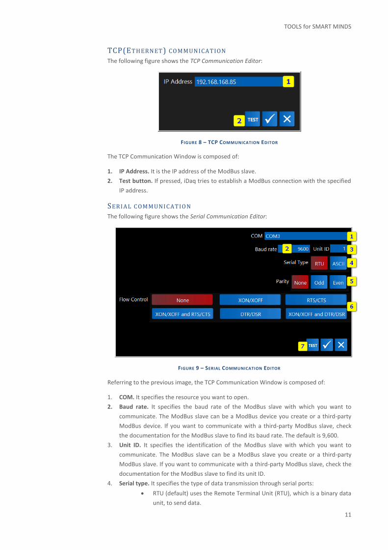
TCP(ET HERN ET) CO MMUNI CATION
The following figure shows the TCP Communication Editor:
FIGURE 8 – TCP COMMUNICATION EDITOR
The TCP Communication Window is composed of:
1. IP Address. It is the IP address of the ModBus slave.
2. Test button. If pressed, iDaq tries to establish a ModBus connection with the specified
IP address.
SERI AL COMMUNI CATIO N
The following figure shows the Serial Communication Editor:
FIGURE 9 – SERIAL COMMUNICATION EDITOR
Referring to the previous image, the TCP Communication Window is composed of:
1. COM. It specifies the resource you want to open.
2. Baud rate. It specifies the baud rate of the ModBus slave with which you want to
communicate. The ModBus slave can be a ModBus device you create or a third-party
ModBus device. If you want to communicate with a third-party ModBus slave, check
the documentation for the ModBus slave to find its baud rate. The default is 9,600.
3. Unit ID. It specifies the identification of the ModBus slave with which you want to
communicate. The ModBus slave can be a ModBus slave you create or a third-party
ModBus slave. If you want to communicate with a third-party ModBus slave, check the
documentation for the ModBus slave to find its unit ID.
4. Serial type. It specifies the type of data transmission through serial ports:
• RTU (default) uses the Remote Terminal Unit (RTU), which is a binary data
unit, to send data.

ModBus iDaq Component – User Guide
12
• ASCII uses human-readable characters to send data.
5. Parity. It specifies the parity of the ModBus slave with which you want to
communicate. The ModBus slave can be a ModBus slave you create or a third-party
ModBus slave. If you want to communicate with a third-party ModBus slave, check the
documentation for the ModBus slave to find its parity.
• None specifies to use no parity bit. If you specify None for parity, the number
of stop bits indicating the end of a frame is 2.
• Odd specifies to use odd parity. If you specify Odd for parity, the number of
stop bits indicating the end of a frame is 1.5.
• Even specifies to use even parity. If you specify Even for parity, the number of
stop bits indicating the end of a frame is 1.5.
6. Flow control. It specifies the flow control of the ModBus slave with which you want to
communicate. The ModBus slave can be a ModBus slave you create or a third-party
ModBus slave. If you want to communicate with a third-party ModBus slave, check the
documentation for the ModBus slave to find its flow control.
• None does not use flow control. The transfer mechanism assumes buffers on
both sides of the connection to be large enough to hold all data transferred.
• XON/XOFF uses the XON and XOFF characters to perform flow control. When
the receiving buffer is almost full, the transfer mechanism controls the input
flow by sending XOFF. When the buffer receives XOFF, the transfer
mechanism controls the output flow by suspending transmission.
• RTS/CTS uses the RTS output signal and the CTS input signal to perform flow
control. When the receiving buffer is almost full, the transfer mechanism
controls the input flow by unasserting the RTS signal. When the buffer
unasserts the CTS signal, the transfer mechanism controls the output flow by
suspending the transmission.
• XON/XOFF and RTS/CTS uses the XON and XOFF characters, the RTS output
signal, and the CTS input signal to perform flow control. When the receiving
buffer is almost full, the transfer mechanism controls the input flow by
sending XOFF and unasserting the RTS signal. When the buffer receives XOFF,
the transfer mechanism controls the output flow by suspending transmission.
• DTR/DSR uses the DTR output signal and the DSR input signal to perform flow
control. When the receiving buffer is almost full, the transfer mechanism
controls the input flow by unasserting the DTR signal. When the buffer
unasserts the DSR signal, the transfer mechanism controls the output flow by
suspending the transmission.
XON/XOFF and DTR/DSR uses the XON and XOFF characters, the DTR output
signal, and the DSR input signal to perform flow control. When the receiving
buffer is almost full, the transfer mechanism controls the input flow by
sending XOFF and unasserting the DTR signal. When the buffer receives XOFF
and unasserts the DSR signal, the transfer mechanism controls the output flow
by suspending transmission.
3. Test button. If pressed, iDaq tries to establish a ModBus connection with the specified
connection setup.

TOOLS for SMART MINDS
13
MODBUS CAPABILITIES As shown in the following figure, to edit settings of a ModBus device, open Device &
Sensors tab and click on the device icon, ModBus device editor will be displayed as
indicated in following figure.
FIGURE 10 – MODBUS DEVICE EDITOR
ModBus devices has several capabilities:
• Analog acquisition. It is used to create analog input channels starting from ModBus
register memory block.
• Digital acquisition. It is used to create digital input channels starting from either
register or coil ModBus memory block.
• VCC. It allows the definition of virtual channels calculated from analog real
channels.
• Analog generation. It is used to write ModBus register starting from analog output
channels.
• Digital acquisition. It is used to write ModBus register starting from digital output
channels.
Referring to the previous figure, ModBus device editor is composed of the following
elements:

ModBus iDaq Component – User Guide
14
1. Analog acquisition. It allows the management of common properties. For more
details view section General Capability Settings.
2. Channel editor (Analog input). It allows the management of analog input
channels.
3. Digital acquisition. It allows the management of common properties. For more
details view section General Capability Settings.
4. Channel editor (Digital input). It allows the management of digital input channels.
5. Virtual Channel editor. It allows the management of virtual channels.
6. Analog generation. It allows the management of common properties. For more
details view section General Capability Settings.
7. Channel Editor (Analog Output). It allows the management of analog output
channels.
8. Digital generation. It allows the management of common properties. For more
details view section General Capability Settings.
9. Channel Editor (Digital Output). It allows the management of digital output
channels.
10. Actual Status. It shows the state of the driver, for example initialization or running.
11. Product page.
12. Device Custom Description. It shows the custom description, if any. Click on it to
add a description or to edit.
13. Reboot settings. For more details view section Reboot Settings.
14. Advanced settings. For more details view section Advanced Settings.
15. Add optional capability. It allows to add capabilities inside the device. It is
required to be used by an expert user.
16. Device reboot.
17. User guide.
Please note that channel configuration is independent from the communication type in use
(TCP or Serial).
GENERAL CAPABILITY SETTINGS General Capability Settings are available from the device editor, for the following
functionalities:
• Analog acquisition;
• Digital acquisition;
• Analog generation;
• Digital generation.
Each of the capabilities listed above has its own editor to configure the related handshakes
and texts.

TOOLS for SMART MINDS
15
FIGURE 11 GENERAL CAPABILITY SETTINGS EDITOR
Referring to the previous figure, General Capability Settings editor is composed of the
following elements:
1. Handshake Settings. It allows the management of Handshake Settings. Enable “Use
handshake during reading operations” for analog and digital acquisition or “Use
handshake during writing operations” for analog and digital generation. For more
details view section Handshake Settings.
2. Text Acquisition Configuration. It allows management of text acquisition/generation
settings.
HAN DS HAK E SET TIN GS
Handshake settings are available in the General Capability Settings.
The handshake functionality changes depending on whether it is an acquisition or
generation capability.
HA N D S H A K E F U N C T I O N A L I T Y F O R AN A L O G A N D D I G I T A L A C Q U I S I T I O N
In the acquisition capability (analog and digital acquisition), the handshake channel is
written periodically. It is used to send periodic commands to the ModBus device to
which it is connected to force the ModBus registers to be updated, for example.
HA N D S H A K E F U N C T I O N A L I T Y F O R AN A L O G A N D D I G I T A L G E N E R A T I O N
In generation capabilities (analog and digital generation), the handshake channel is
used to notify the connected ModBus device that a write operation has been
performed. The handshake channel is written every time a write operation is
performed.
Handshake settings are shown below.

ModBus iDaq Component – User Guide
16
FIGURE 12 HANDSHAKE SETTINGS IN GENERAL CAPABILITY SETTINGS EDITOR
Referring to the previous figure, handshake settings are composed of the following
elements:
1. Use handshake during reading/writing operations. If enabled, it uses handshake
during reading or writing operations, according to the functionality in which the
property management is located: acquisition or generation.
2. Value to write. It specifies the value to write in the ModBus registers used as
handshake.
3. Handshake Period. It is only supported by acquisition capabilities. It represents the
writing rate of the handshake channel.
4. Waiting time before writing. It is only supported by generation capabilities. It specifies
the delay time between writing any channel and writing the handshake channel. It is
expressed in seconds.
5. Reset handshake after writing. If enabled, it resets to 0 the handshake channel
previously written.
6. Waiting time before reset the handshake. If the previous element is enabled, it
specifies the waiting time between writing the handshake channel and its reset. It is
expressed in seconds.
7. Handshake Channels Configuration. It allows definition and configuration of
handshake channels, which is described below.

TOOLS for SMART MINDS
17
HA N D S H A K E C H A N N E L S C O N F I G U R A T I O N
Handshake Channels list is available from the handshake settings in General Capability
Settings editor (Handshake Channels Configuration button).
FIGURE 13 HANDSHAKE CHANNELS LIST
Referring to the previous figure, the list of handshake channels is composed of the
following elements:
1. List of handshake channels. It shows the list of the available handshake channels,
the registers and the address set.
2. Add. Use this button to add a new element to read/write.
3. Edit. Use this button to edit selected text element.
4. Remove. Use this button to remove selected text elements.
5. Remove All. Use this button to remove all text elements in the list.
From this window, by clicking Add or Edit buttons, it is possible to configure a handshake
channel, as shown in the following figure.

ModBus iDaq Component – User Guide
18
FIGURE 14 CONFIGURE HANDSHAKE CHANNEL
Referring to the previous figure, the editor to configure handshake channel is composed of
the following elements:
1. Name.
2. Min value. It is the minimum expected value for current channel.
3. Max value. It is the maximum expected value for current channel.
4. Units. It is the unit expected for current channel.
5. Res. Prefix. It is the prefix used to build the channel resource name. It is an advanced
option for advanced users only.
6. IP Address. It specifies the IP Address of the physical device.
7. Register Address. It indicates the register address.
8. Number of Registers. It indicates the number of registers associated to current
channel. It allows the acquisition of signals that are codified on more than one register.
9. Memory Block. It indicates the type of memory to access: Input Register or Holding
Register.
10. Read Mode:
• 2 Bytes. Both register bytes may be written. If 2 Bytes is selected, Bit number may
refer to any bit from 0 to 15.
• 1 Byte High. The highest byte only may be written. If 1 Byte High is selected, Bit
number may refer to any bit from 0 to 7

TOOLS for SMART MINDS
19
• 1 Byte Low. The lowest byte only may be written. If 1 Byte Low is selected, Bit
number may refer to any bit from 0 to 7.
11. LSB/MSB (Most significant byte/Less significant byte). ModBus register data are
unsigned 16 bit values. If LSB is used, bytes are swapped before writing them in the
register; vice versa, if MSB is used, byte order remains unchanged.
12. Conversion. It represents how data is encoded. Supported conversions are:
• None. It does not do any conversion of data.
• Use sign bit. It uses the first bit as sign. 1 = negative; 0 = positive.
• Float. It converts the 32-bit data in float according to the standard IEEE 754.
• To signed integer. It uses 2-complement conversion.
13. Rescale data. If enabled, data is processed as follow: Data x Multiplier / Divider +
Offset. This can be useful to direct convert read data into a physical quantity.
14. Multiplier. It is used only if Rescale data is enabled.
15. Divider. It is used only if Rescale data is enabled.
16. Offset. It is used only if Rescale data is enabled.
17. Use Single Bit. If enabled, a specific bit is used to define value of current channel.
18. Bit number. It specifies the bit to use. It is 0-based.
19. Test Value. It is the value used for channel test. It is available only for analog and digital
generation funcions.
20. Test button. Use this button to test the channel.
21. Group. Use this to assign a group for the channel.
22. Waveform Processing Unit (WPU). WPUs are tools designed for signal processing:
further details are included in the Waveform Processing Unit user guide.

ModBus iDaq Component – User Guide
20
TEXT ACQUI SITION /GENERATION CON FI GUR ATION
Text Acquisition/Generation Configuration is available from the General Capability
Settings, as reported below.
FIGURE 15 TEXT ACQUISITION/GENERATION CONFIGURATION IN THE GENERAL CAPABILITY SETTINGS
EDITOR
FIGURE 16 TEXT ACQUISITION/GENERATION CONFIGURATION EDITOR
As reported by the figure above, Text Acquisition/Generation Configuration editor is
composed of:
1. Text List. It shows the assigned name to the text, the type of registers and the used
address.
2. Add. Use this button to add a new text element to read/write. For more details view
section Adding a new text element to read/write.
3. Edit. Use this button to edit selected text element.
4. Remove. Use this button to remove selected elements.
5. Remove All. Use this button to remove all the text elements in the list.

TOOLS for SMART MINDS
21
AD D I N G A N E W T E X T E L E M E N T T O R E A D /W R I T E
To add a new text element to read/write, click on the Add button in the Text Acquisition
Configuration editor.
FIGURE 17 EDITOR TO ADD A NEW TEXT ELEMENT TO READ/WRITE IN ANALOG ACQUISITION
As reported by the figure above, editor to add a new text element to read/write is
composed of:
1. Name.
2. Memory block. It specifies the type of memory to access: Input Register or Holding
Register.
3. Number of char per register. It specifies the number of characters to read/write for
each register (1 or 2).
4. LSB/MSB (Most significant byte/Less significant byte). ModBus register data are
unsigned 16 bit values. If LSB is used, bytes are swapped before writing them in the
register; vice versa, if MSB is used, byte order remains unchanged.
5. Start Address. It specifies the first register from which the data is read.
6. Number of Chars. It specifies the number of characters to read/write.
7. Test string (available only for analog generation). It is the text string used for test. It is
available only in the editor to add a new text element to write in analog generation.
8. Test. Use this button to test the channel.

ModBus iDaq Component – User Guide
22
REBOOT SETTINGS Reboot Settings are available from the device editor.
FIGURE 18 REBOOT SETTINGS EDITOR
As reported by the figure above, Advanced Settings editor is composed of:
1. Validation Delay. It specifies time that must elapse without errors from Device Boot to
confirm that device is working properly. iDaq in fact waits a certain time from when you are
connected to say that the device is really working in order to avoid doing SPAM emails with
connection error/success emails. During this validation time, the data must arrive from the
device and there must be no communication errors.
2. Reboot Automatically in case of Failure. If checked, it enables automatic reboot in case
of disconnection.
3. Reboot Trials before Notification. It specifies the number of consecutive reboot trials
before iDaq notification of “device disconnected”.
4. Refer to Calendar Work Time. If checked, iDaq refers to Calendar Work Time to Reboot
device when is not responding. To set a work calendar, iDaq needs to connect to the
database of the application “Digital Factory 4.0 Calendar”. To set work calendar, from the
main panel select: Configuration Settings > iDaq Option. For more details, please refer to
the iDaq Device Manager User Guide.
5. Max Consecutive Trials. It specifies the number of consecutive reboot trials. After these
trials, the device remains disconnected.
6. Delay Before Consecutive Reboots. It specifies the delay between two consecutive
reboot trials.
7. Indicator of empty email address. If it visible, it means email address list is empty, so no
notification can be sent.
8. Email addresses list configuration. It allows the management of email addresses to send
reboot notifications to.

TOOLS for SMART MINDS
23
ADVANCED SETTINGS Advanced Settings are available from the ModBus device editor.
FIGURE 19 ADVANCED SETTINGS EDITOR
As reported by the following figure, Advanced Setting editor is composed of:
1. Communication type. It can be TCP (Ethernet connection) or serial.
Communication type can be changed even after the creation of the iDaq ModBus
device. For more details, view sections TCP(Ethernet) communication and Serial
communication.
2. Resource. It shows IP address or serial resource according to the communication
type in use.
3. Timeout. It specifies the read/write operation timeout and it is expressed in
milliseconds.
4. Delay between consecutives reads. It specifies if the iDaq component must wait
for a specific time between two consecutive read requests. Default value is 0.
5. Connection attempts. It specifies the number of consecutives reconnection
attempts. Overcome this value, ModBus device returns an error and stops.
6. Read Period. It specifies the acquisition rate, i.e. how often it reads on the device.
The value applies for all types of signals, both analog and digital, and it is
expressed in milliseconds.
7. Optimize Read. If enabled, the driver reads all the necessary records at once. In
particular, in a single read operation it accesses contiguous registers from the
lowest to the highest address used by user-configured channels. For example, if
you have configured 3 channels associated with addresses 5, 20 and 15
respectively, the ModBus driver reads all contiguous registers from 5 to 20, then
extracts the values from registers 5, 20 and 15 to define the values of the
respective channels. Usually this method is faster, but not all devices support it. If

ModBus iDaq Component – User Guide
24
not enabled, the driver reads only the necessary data, one to one. Usually this
method takes longer.
8. Check Ping before connection. If enabled, the driver pings the hardware to check
if it is available. If there is no response, the connection is not made.
9. Configure Start-up channel List. It allows to configure channels to write at every
start-up of the device. For more details, view section Start-Up Channel
Configuration.
10. Export channels to a CSV file. It allows to export all channels defined in all
capabilities to a CSV file.
11. Communication editor. It shows the communication editor according to the
communication type in use (TCP or Serial). For more details, view sections
TCP(Ethernet) communication and Serial communication.
STAR T-UP CHANN EL CONFI GUR ATION
Start-Up Channel List is available in Advanced Settings Editor, and it is shown in the
following figure. It allows to write configured channels at every start-up on the device. This
feature is useful when, for example, you need to initialize the ModBus device before
proceeding with the acquisition.
FIGURE 20 - EMPTY START-UP CHANNEL LIST
Start-Up Channel List is composed of the following elements:
1. List of Start-Up Channels. The list shows the name of the channels, the resource and the value to write at start-up.
2. Add. It allows to add a channel.
3. Remove. It allows to remove selected channels in the list.

TOOLS for SMART MINDS
25
To add a new channel click on Add and select the channel to be added in the list of start-up
channels. You can choose from any of the previously configured generation channels.
Figure of the list is shown below.
FIGURE 21 - CHANNEL SELECTION
Click again on Add button. The following window will appear.
FIGURE 22 - CONFIGURING VALUE TO WRITE IN THE SELECTED CHANNEL
Insert the value to write in the text box and click again on Add button.
The set channel will appear in the list, as shown below.
FIGURE 23 - CONFIGURED CHANNEL IN START-UP CHANNEL LIST
Repeat the process for every channel to configure.
ModBus iDaq Component – User Guide
26
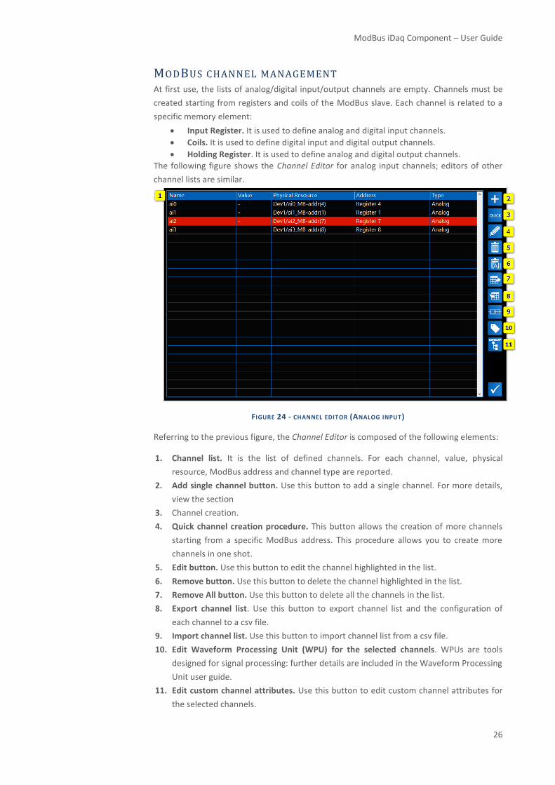
MODBUS CHANNEL MANAGEMENT At first use, the lists of analog/digital input/output channels are empty. Channels must be
created starting from registers and coils of the ModBus slave. Each channel is related to a
specific memory element:
• Input Register. It is used to define analog and digital input channels.
• Coils. It is used to define digital input and digital output channels.
• Holding Register. It is used to define analog and digital output channels. The following figure shows the Channel Editor for analog input channels; editors of other
channel lists are similar.
FIGURE 24 - CHANNEL EDITOR (ANALOG INPUT)
Referring to the previous figure, the Channel Editor is composed of the following elements:
1. Channel list. It is the list of defined channels. For each channel, value, physical
resource, ModBus address and channel type are reported.
2. Add single channel button. Use this button to add a single channel. For more details,
view the section
3. Channel creation.
4. Quick channel creation procedure. This button allows the creation of more channels
starting from a specific ModBus address. This procedure allows you to create more
channels in one shot.
5. Edit button. Use this button to edit the channel highlighted in the list.
6. Remove button. Use this button to delete the channel highlighted in the list.
7. Remove All button. Use this button to delete all the channels in the list.
8. Export channel list. Use this button to export channel list and the configuration of
each channel to a csv file.
9. Import channel list. Use this button to import channel list from a csv file.
10. Edit Waveform Processing Unit (WPU) for the selected channels. WPUs are tools
designed for signal processing: further details are included in the Waveform Processing
Unit user guide.
11. Edit custom channel attributes. Use this button to edit custom channel attributes for
the selected channels.

TOOLS for SMART MINDS
27
12. Edit Group Attribute for selected channels. Use this button to edit Group Attribute for
the selected channels.
CHANN EL CR EATION
As reported before, ModBus driver supports two different ways to create channels:
1. Single channel creation.
2. Quick channel creation.
S I N G L E C H A N N E L C R E A T I O N – A N A L O G I N P U T
To create a single analog input channel, press Add single channel button from the Channel
Editor (Analog Input Capability). The following window will appear.
FIGURE 25 ADD SINGLE CHANNEL PROCEDURE
Elements in this window are:
1. Channel name.
2. Min value. It is the minimum expected value.
3. Max value. It is the maximum expected value.
4. Units. It specifies the unit of measurement.
5. Res. Prefix. It is the prefix used to build the channel resource name. It is an
advanced option for advanced users only.
6. IP Address. It specifies the IP Address of the physical device.

ModBus iDaq Component – User Guide
28
7. Register Address. It specifies the ModBus input register address used to
created current channel (data read from this address will be used to define
values of the current analog input channel).
8. Number of registers. It indicates the number of registers associated to current
channel. It allows the acquisition of signals that are codified on more than one
register.
9. Memory block. It specifies the type of memory to access to acquire data.
10. Read Mode:
• 2 Byes: both register bytes are used to build the analog signal.
• 1 Byte High. The high byte only is used to build the analog signal.
• 1 Byte Low. The low byte only is used to build the analog signal.
11. LSB/MSB (Most significant byte/Less significant byte). Data acquired with
ModBus are unsigned 16 bit values. If LSB, is used, read bytes are swapped;
vice versa, if MSB is used, byte order remains unchanged.
12. Conversion. It represents how data is encoded. Supported conversions are:
• None. It does not do any conversion of data.
• Use sign bit. It uses the first bit as sign. 1 = negative; 0 = positive.
• Signed integer. It uses 2-complement conversion.
• Float. It converts the 32-bit data in float according to the standard IEEE
754.
Not all conversion types are available for all data types. This field is not
available if selected Data type is Bit.
13. Rescale data. If enabled, data is processed as follow: Data x Multiplier /
Divider. This can be useful to direct convert read data into a physical quantity.
14. Multiplier. It is used only if Rescale data is enabled.
15. Divider. It is used only if Rescale data is enabled.
16. Offset. It is used only if Rescale data is enabled.
17. Use single bit. If enabled, it extracts a single bit (from 1 to 16).
18. Bit number. It specifies the bit number to extract. If it’s 0, it extracts the first
bit.
19. Test button. Use this button to test the channel.
20. Group. Use this to assign a group for the channel.
21. Waveform Processing Unit (WPU). WPUs are tools designed for signal
processing: further details are included in the Waveform Processing Unit user
guide.
After confirmation, a single channel is created, and it is added to the channel list of the
Channel Editor (Analog Input Capability).

TOOLS for SMART MINDS
29
Q U I C K C R E A T I O N - A N A L O G I N P U T
This mode allows the creation of more channels starting from a specific ModBus address.
This procedure allows you to create more analog input channels in one shot. To create
channels in this way, press the Quick channel creation button from the Channel Editor. The
following window will appear.
FIGURE 26 QUICK CHANNEL CREATION
Elements in this window are:
1. Base Name. it is the base name used to build channels names.
2. Min value. It is the minimum expected value.
3. Max value. It is the maximum expected value.
4. Units. It is the unit expected for current channels.
5. Register Address. It specifies the ModBus input register address used to
created current channels (data read from this address will be used to define
values of the current analog input channels).
6. Number of channels. It specifies the number of channels to be created.
7. Number of Registers per channel. It indicates the number of registers
associated to current channel. It allows the acquisition of signals that are
codified on more than one register.
8. Address preview. It shows the preview of used addresses.
9. Read Mode:

ModBus iDaq Component – User Guide
30
• 2 Byes: both register bytes are used to build the analog signal.
• 1 Byte High. The high byte only is used to build the analog signal.
• 1 Byte Low. The low byte only is used to build the analog signal.
10. LSB/MSB (Most significant byte/Less significant byte). Data acquired with
ModBus are unsigned 16 bit values. If LSB, is used, read bytes are swapped;
vice versa, if MSB is used, byte order remains unchanged.
11. Conversion. It represents how data is encoded. Supported conversions are:
• None. It does not do any conversion of data.
• Use sign bit. It uses the first bit as sign. 1 = negative; 0 = positive.
• Float. It converts the 32-bit data in float according to the standard IEEE
754.
• To signed integer. It uses 2-complement conversion.
12. Rescale data. If enabled, data is processed as follow: Data x Multiplier /
Divider. This can be useful to direct convert read data into a physical quantity.
13. Multiplier. It is used only if Rescale data is enabled.
14. Divider. It is used only if Rescale data is enabled.
15. Test button. Use this button to test channels.
If you specify 5 as number of channels, 15 as register address, and Channel as channel base,
the following five channels will be created:
• Channel _0 – index: 15
• Channel _1 – index: 16
• Channel _2 – index: 17
• Channel _3 – index: 18
• Channel _4 – index: 19

TOOLS for SMART MINDS
31
S I N G L E C H A N N E L C R E A T I O N – D I G I T A L I N P U T
To create a single digital input channel, press Add single channel button from the Channel
Editor (Digital Input Capability). The following window will appear.
FIGURE 27 ADD SINGLE CHANNEL PROCEDURE
Elements in this window are:
1. Channel name.
2. Res. Prefix. It is the prefix used to build the channel resource name. It is an
advanced option for advanced users only.
3. IP Address. It specifies the IP Address of the physical device.
1. Memory Block. It specifies the memory block used to defined current channel:
• Input Register
• Holding Register
• Coils
• Discrete Inputs
4. Bit number. It is available only if Register Memory block is selected. As a
register is a 16-bit value, this field specified which bit corresponds to current
digital channel.
5. Register/Coil Address. It specifies the ModBus input register address or the
coil address according to the selected Memory Block.
6. Read Mode:
• 2 Bytes. Both register bytes are used to build the digital channel. If 2
Bytes is selected, Bit number may refer to any bit from 0 to 15.
• 1 Byte High. The highest byte only is used to build the digital channel.
If 1 Byte High is selected, Bit number may refer to any bit from 0 to 7

ModBus iDaq Component – User Guide
32
• 1 Byte Low. The lowest byte only is used to build channel signal. If 1
Byte Low is selected, Bit number may refer to any bit from 0 to 7.
7. LSB/MSB (Most significant byte/Less significant byte). Data acquired with
ModBus are unsigned 16 bit values. If LSB, is used, read bytes are swapped;
vice versa, if MSB is used, byte order remains unchanged.
8. Test button. Use this button to test current channel.
9. Group. Use this to assign a group for the channel.
After confirmation, a single channel is created, and it is added to the channel list of the
Channel Editor (Digital Input Capability)
Q U I C K C R E A T I O N - D I G I T A L I N P U T
This mode allows the creation of more channels starting from a specific ModBus address.
This procedure allows you to create more channels in one shot. To create channels in this
way, press the Quick channel creation button from the Channel Editor. The following
window will appear.
FIGURE 28 QUICK CHANNEL PROCEDURE
Elements in this window are:
1. Base Name. it is the base name used to build channels names.
2. Register/Coil Address. It specifies the ModBus input register address or the
coil address according to the selected Memory Block.
3. Number of channels. It specifies the number of channels to be created.
4. Memory Block. It specifies the memory block used to defined current digital
channel:
• Input Register
• Holding Register
• Coils
• Discrete Inputs

TOOLS for SMART MINDS
33
5. Address preview. It shows the preview of used addresses.
6. Read Mode:
• 2 Byes. Both register bytes are used to build the digital channel.
• 1 Byte High. The high byte only is used to build the digital channel.
• 1 Byte Low. The low byte only is used to build channel signal.
7. LSB/MSB (Most significant byte/Less significant byte). Data acquired with
ModBus are unsigned 16 bit values. If LSB, is used, read bytes are swapped;
vice versa, if MSB is used, byte order remains unchanged.
8. Test button. Use this button to test current channel.
If you specify 5 as number of channels, 15 as address, Register as memory block, and
Channel as channel base, the following five channels will be created:
• Channel _0 – register address 15 - bit: 0
• Channel _1 – register address 15 – bit: 1
• Channel _2 – register address 15 – bit: 2
• Channel _3 – register address 15 – bit: 3
• Channel _4 – register address 15 – bit: 4
If you specify 5 as number of channels, 15 as address, Coil as memory block, and Channel as
channel base, the following five digital input channels will be created:
• Channel _0 – coil address 15
• Channel _1 – coil address 16
• Channel _2 – coil address 17
• Channel _3 – coil address 18
• Channel _4 – coil address 19

ModBus iDaq Component – User Guide
34
S I N G L E C H A N N E L C R E A T I O N – A N A L O G O U T P U T
To create a single analog output channel, press Add single channel button from the
Channel Editor (Analog Output Capability). The following window will appear.
FIGURE 29 ADD SINGLE CHANNEL PROCEDURE
Elements in this window are:
1. Name.
2. Min value. It is the minimum expected value for current channel.
3. Max value. It is the maximum expected value for current channel.
4. Units. It is the unit expected for current channel.
5. Res. Prefix. It is the prefix used to build the channel resource name. It is an
advanced option for advanced users only.
6. IP Address. It specifies the IP Address of the physical device.
7. Register Address. It indicates the register address.
8. Number of Registers. It indicates the number of registers associated to
current channel. It allows the acquisition of signals that are codified on more
than one register.
9. Memory Block. It indicates the type of memory to access: Input Register or
Holding Register.
10. Read Mode:
• 2 Bytes. Both register bytes may be written. If 2 Bytes is selected, Bit
number may refer to any bit from 0 to 15.

TOOLS for SMART MINDS
35
• 1 Byte High. The highest byte only may be written. If 1 Byte High is
selected, Bit number may refer to any bit from 0 to 7
• 1 Byte Low. The lowest byte only may be written. If 1 Byte Low is
selected, Bit number may refer to any bit from 0 to 7.
11. LSB/MSB (Most significant byte/Less significant byte). ModBus register data
are unsigned 16 bit values. If LSB is used, bytes are swapped before writing
them in the register; vice versa, if MSB is used, byte order remains
unchanged.
12. Conversion. It represents how data is encoded. Supported conversions are:
• None. It does not do any conversion of data.
• Use sign bit. It uses the first bit as sign. 1 = negative; 0 = positive.
• Float. It converts the 32-bit data in float according to the standard IEEE
754.
• To signed integer. It uses 2-complement conversion.
13. Rescale data. If enabled, data is processed as follow: Data x Multiplier /
Divider + Offset. This can be useful to direct convert read data into a physical
quantity.
14. Multiplier. It is used only if Rescale data is enabled.
15. Divider. It is used only if Rescale data is enabled.
16. Offset. It is used only if Rescale data is enabled.
17. Use Single Bit. If enabled, a specific bit is used to define value of current
channel.
18. Bit number. It specifies the bit to use. It is 0-based.
19. Test Value. It is the value used for channel test. It is available only for analog
and digital generation funcions.
20. Test button. Use this button to test the channel.
21. Group. Use this to assign a group for the channel.
22. Waveform Processing Unit (WPU). WPUs are tools designed for signal
processing: further details are included in the Waveform Processing Unit user
guide.
After confirmation, a single channel is created and it is added to the channel list of the
Channel Editor (Analog Output Capability).

ModBus iDaq Component – User Guide
36
Q U I C K C R E A T I O N - A N A L O G O U T P U T
This mode allows the creation of more channels starting from a specific ModBus address.
This procedure allows you to create more channels in one shot. To create channels in this
way, press the Quick channel creation button from the Channel Editor. The following
window will appear.
FIGURE 30 ADD SINGLE CHANNEL PROCEDURE
Elements in this window are:
1. Base Name. it is the base name used to build channels names.
2. Min value. It is the minimum expected value.
3. Max value. It is the maximum expected value.
4. Units. It is the unit expected for current channels.
5. Register Address. It specifies the ModBus output register address used to
created current channels.
6. Number of channels. It specifies the number of channels to be created.
7. Number of Registers per channel. It indicates the number of registers
associated to current channel. It allows the acquisition of signals that are
codified on more than one register.
8. Address preview. It shows the preview of used addresses.
9. Read Mode:

TOOLS for SMART MINDS
37
• 2 Byes: both register bytes are used to build the analog signal.
• 1 Byte High. The high byte only is used to build the analog signal.
• 1 Byte Low. The low byte only is used to build the analog signal.
10. LSB/MSB (Most significant byte/Less significant byte). Data acquired with
ModBus are unsigned 16 bit values. If LSB, is used, read bytes are swapped;
vice versa, if MSB is used, byte order remains unchanged.
11. Conversion. It represents how data is encoded. Supported conversions are:
• None. It does not do any conversion of data.
• Use sign bit. It uses the first bit as sign. 1 = negative; 0 = positive.
• Float. It converts the 32-bit data in float according to the standard IEEE
754.
• To signed integer. It uses 2-complement conversion.
12. Rescale data. If enabled, data is processed as follow: Data x Multiplier /
Divider. This can be useful to direct convert read data into a physical quantity.
13. Test value. It is the value used for rescaling data test.
14. Multiplier. It is used only if Rescale data is enabled.
15. Divider. It is used only if Rescale data is enabled.
16. Offset. It is used only if Rescale data is enabled.
17. Test button. Use this button to test channels.
If you specify 5 as number of channels, 15 as register address, and Channel as channel base,
the following five analog output channels will be created:
• Channel _0 – index: 15
• Channel _1 – index: 16
• Channel _2 – index: 17
• Channel _3 – index: 18
• Channel _4 – index: 19

ModBus iDaq Component – User Guide
38
S I N G L E C H A N N E L C R E A T I O N – D I G I T A L O U T P U T
To create a single digital output channel, press Add single channel button from the Channel
Editor (Digital Output Capability). The following window will appear.
FIGURE 31 ADD SINGLE CHANNEL PROCEDURE
Elements in this window are:
1. Channel name.
2. Res. Prefix. It is the prefix used to build the channel resource name. It is an
advanced option for advanced users only.
3. IP Address. It specifies the IP Address of the physical device.
4. Memory Block. It specifies the memory block used to defined current channel:
• Input Register
• Holding Register
• Coils
• Discrete Inputs
5. Bit number. It is available only if Register Memory block is selected. As a
register is a 16-bit value, this field specified which bit corresponds to current
digital channel.
6. Register/Coil Address. It specifies the ModBus input register address or the
coil address according to the selected Memory Block.
7. Read Mode:
• 2 Bytes. Both register bytes are used to build the digital channel. If 2
Bytes is selected, Bit number may refer to any bit from 0 to 15.
• 1 Byte High. The highest byte only is used to build the digital channel.
If 1 Byte High is selected, Bit number may refer to any bit from 0 to 7

TOOLS for SMART MINDS
39
• 1 Byte Low. The lowest byte only is used to build channel signal. If 1
Byte Low is selected, Bit number may refer to any bit from 0 to 7.
8. LSB/MSB (Most significant byte/Less significant byte). Data acquired with
ModBus are unsigned 16 bit values. If LSB, is used, read bytes are swapped;
vice versa, if MSB is used, byte order remains unchanged.
9. Test Value. It is the value used for test.
10. Test button. Use this button to test current channel.
11. Group. Use this to assign a group for the channel.
After confirmation, a single channel is created and it is added to the channel list of the
Channel Editor (Digital Output Capability).
Q U I C K C R E A T I O N - D I G I T A L O U T P U T
This mode allows the creation of more digital output channels starting from a specific
ModBus address. This procedure allows you to create more channels in one shot. To create
channels in this way, press the Quick channel creation button from the Channel Editor. The
following window will appear.
FIGURE 32 ADD SINGLE CHANNEL PROCEDURE
Elements in this window are:
1. Base Name. it is the base name used to build channels names.
2. Register/Coil Address. It specifies the ModBus input register address or the
coil address according to the selected Memory Block.
3. Number of channels. It specifies the number of channels to be created.

ModBus iDaq Component – User Guide
40
4. Memory Block. It specifies the memory block used to defined current digital
channel:
• Input Register
• Holding Register
• Coils
• Discrete Inputs
5. Address preview. It shows the preview of used addresses.
6. Read Mode:
• 2 Byes. Both register bytes are used to build the digital channel.
• 1 Byte High. The high byte only is used to build the digital channel.
• 1 Byte Low. The low byte only is used to build channel signal.
7. LSB/MSB (Most significant byte/Less significant byte). Data acquired with
ModBus are unsigned 16 bit values. If LSB, is used, read bytes are swapped;
vice versa, if MSB is used, byte order remains unchanged.
8. Test Value. It is the value used for test.
9. Test button. Use this button to test current channel.
If you specify 5 as number of channels, 15 as address, Register as memory block, and
Channel as channel base, the following five digital output channels will be created:
• Channel _0 – register address 15 - bit: 0
• Channel _1 – register address 15 – bit: 1
• Channel _2 – register address 15 – bit: 2
• Channel _3 – register address 15 – bit: 3
• Channel _4 – register address 15 – bit: 4
If you specify 5 as number of channels, 15 as address, Coil as memory block, and Channel as
channel base, the following five digital output channels will be created:
• Channel _0 – coil address 15
• Channel _1 – coil address 16
• Channel _2 – coil address 17
• Channel _3 – coil address 18
• Channel _4 – coil address 19

TOOLS for SMART MINDS
41
FURTHER DETAILS iDaq product page: www.idaq-datalogger.com
iDaq ADD-ON Store www.idaq-datalogger.com/en/products
Support: www.idaq-datalogger.com/en/support
ModBus Driver for iDaq product page: https://www.idaq-
datalogger.com/en/products/drivers/modbus-driver-for-idaq
ModBus Driver for iDaq User Guide: https://www.idaq-
datalogger.com/_documents/en/ModBus-User-Guide-2-0.pdf
Getting stated with ModBus Driver for iDaq: https://www.idaq-
datalogger.com/_documents/en/Getting-Started-with-ModBus-2-0.pdf
Introduction to ModBus http://www.ni.com/white-paper/7675/en/
ModBus organization website http://www.modbus.org/