model 383 - files.pentairliterature.comfiles.pentairliterature.com/aurora/a-03-284.pdf · model 383...
TRANSCRIPT

NOTE! To the installer: Please make sure you provide this manual to the owner of the equip ment or to the responsible party who maintains the system.
MODEL 383SINGLE STAGE INLINE FIRE PUMPINSTRUCTION AND REPAIR MANUAL
Part # A-03-284 | © 2012 Pentair Ltd. | 12/03/12

THIS PAGE INTENTIONALLY LEFT BLANK
3
MODEL 383DATED SEPTEMBER 2011SUPERSEDES ITEM 383DATED JULY 2001
ATTENTION: SAFETY WARNINGS:
Read and understand all warnings before installing or servicing pump.
OPERATIONAL LIMITS*:
Maximum Operating Pressure: 175 psi at Temperatures to l50ºF (66°C)
Maximum Operating Temperature: 225°F (107°C)
*See ASTM A126/ANSI B16.l for pressure/temperature ratings of flanges.
ELECTRICAL SAFETY:
HIGH PRESSURE SAFETY:
SERVICE:
Your Aurora pump requires little maintenance other than periodic inspection, occasional cleaning, lubrication of bearings and gland adjustments to minimize packing leakage. The intent of inspection is to prevent breakdown, thus obtaining optimum service life. The liquid end of the pump is lubricated by the fluid being pumped and therefore does not require periodic lubrication. The motor, however, may require lubrication, in which case the motor manufacturer’s recommendation should be followed.
REPAIRS:
Before starting any work, ensure the electrical power is locked out, the system pressure has been lowered to 0 psi and temperature of the unit is at a safe level.
The pump may be disassembled using the illustrations and text provided. Although complete disassembly is covered, it will seldom be necessary to completely disassemble your Aurora pump.
Inspect removed parts at disassembly to determine if they can be reused. Ball bearings that turn roughly or show wear should be replaced. Cracked casings should never be reused. Scored or worn pump shafts should be replaced. Gaskets should be replaced at reassembly simply as a matter of economy. They aremuch less expensive to replace routinely than to replace as the need arises. In general it is economical to return to the manufacturer for repair of only the motor and motor controller.
DISASSEMBLY:
Disassemble only what is needed to make repairs or to accomplish inspection. Proceed to disassemble the pump as follows:
1. Break electrical connections to prevent any possibility of pump starting during disassembly.
2. Remove plug (74) from casing (6) to drain pump.
3. Remove all relief, cooling, flushing, or drain lines from the pump including compression connections (1 & 2), ball valve (75) and tubing (3) if provided. Break suction and discharge connections only if it is desired to remove casing (6).
4. Remove capscrews (5) and two opposite capscrews (41). Thread two capscrews (5) into taps that held capscrews (41) and turn alternately until cover (26) separates from casing. This procedure may vary slightly for some pump sizes. Lift pump assembly with motor from casing (6). Remove gasket (8).
Warning: Electrical Shock Hazard
All electrical connections are to be made by a qualified electrician in accordance with all codes and ordinances. Failure to follow these instructions could result in serious personal injury, death or property damage.
Warning: Electrical Overload Hazard
Ensure all motors have properly sized overload protection.Failure to follow these instructions could result in serious personal injury, death or property damage.
Warning: Sudden Start-Up Hazard
Disconnect and lockout power source before servicing. Failure to follow these instructions could result in serious personal injury, death or property damage.
Warning: High Pressure Hazard
The pump is rated at a maximum of 175 psi at 150°F. Do not exceed this pressure. Install properly sized pressure relief valves in system. Failure to follow these instructions could result in serious personal injury, death or property damage.
CALIFORNIA PROPOSITION 65 WARNING:
Warning: This product and related accessories contain chemicals known to the State of California to cause cancer, birth defects or other reproductive harm.
4
MODEL 383
5. Unscrew impeller screw (9) and remove washer (9A), gasket
(9B) and seal washer (9C).
6. Slide impeller (11) and impeller key (12) from the shaft.Remove O-ring (10).
7. Wearing ring(s) (7 & 16) are pressed into their housings with an interference fit and must be removed with a puller if new rings are required.
8. Remove capscrews (65), gland clamps (22), and gland halves (23).
9. Unscrew remaining capscrews (41) and remove cover assembly (26).
10. Shaft sleeve (25) is slip fit on the shaft and should be easily removed unless the pump has been in service for a long time. In this case, it may be necessary to use a puller. Take care to prevent damaging the surface of the sleeve. Replace the sleeve if it is grooved from wear.
11. The packing (28) and lantern ring (29) (if used) must now be removed from the packing box of cover (26), and the cavity thoroughly cleaned to allow new packing to fit properly. The throat of cover (26) should be checked for excessive wear.
12. If necessary, unscrew capscrews (32) and remove bracket (35) from motor.
REASSEMBLY:
Reassembly will generally be in reverse order of disassembly. Ifdisassembly was not complete, use only those steps related to your particular repair program.
1. Replace wear ring(s) (7 & 16) in casing (6) and cover (26). Rings should not be hammered into place. Use a press or clamp the parts in a bench vice using wooden blocks to protect the rings. It may be necessary to pin or dowel the rings after assembly if the cover or casings has had rings replaced before, since each reassembly can stretch or tear metal and thereby loosen fits. If the facilities are available, it is good practice to take a very light finish cut or to ream the inside diameter of the casing rings after pressing to restore roundness. When rings are pressed, they may get squeezed out of shape.
2. If bracket (35) was removed, position the motor and secure with capscrews (32). Tighten screws evenly to assure proper alignment.
3. Place one ring of packing (28) into cover (26). On successive rings of packing, stagger the packing joints to prevent excessive leakage though the packing box. If lantern ring (29) is used, place a second ring of packing (28) into the cover before installing lantern ring.
There must be two (2) rings of packing in front of lantern ring (29) to assure proper alignment between the lantern ring and the sealing tube connection (1) in the cover (26). Install remaining packing rings (28). Each ring should be tapped firmly in place with a wood or metal bushing.
4. Slide the sleeve (25) through the packing making sure the pin end of the sleeve (25) is in the cover side opposite the gland halves (23).
5. Replace gland halves (23) and place gland clamps (22) over capscrews (65). Tighten capscrews (65) finger tight into cover assembly (26).
NOTE:The slots in gland halves (23) should be diagonal to pump horizontal center line.
6. The cover assembly (26) as a unit may be replaced onto the motor shaft. Align key groove to facilitate impeller reassembly. The cover is held to motor bracket (35) by capscrews (41). These should be installed and tightened at this time.
7. Carefully place O-ring (10) on motor end of impeller (11). Assemble key (12) and impeller (11) to motor shaft. Secure impeller with gasket (9B), washer (9A), seal washer (9C), and impeller screw (9).
8. Install the pipe plug (74) in the pump casing (6). Position a new gasket (8) on casing (6). Lower bracket, cover, and motor assembly onto casing and secure with capscrews (50).
9. If provided, replace compression fittings (1 & 2), ball valve (75), and tubing (3).
10. Secure suction and discharge piping to the pump. Make sure to install gaskets on flanged connections.
11. Connect electricity to the motor.
12. Read carefully the sections of the manual titled INSTALLATION and OPERATION.
STARTING PUMP AFTER REASSEMBLY:
Do not start pump until all air and vapor have been bled and until making sure that there is liquid in the pump to provide the necessary lubrication for the packing.
When the pump is returned to service, additional care must be given to packing box to ensure a proper packing life. It is necessary to allow 60–120 drops leakage per minute through thepacking for lubrication purposes. If the flow rate is other than this, the capscrews should be either loosened or tightened one quarter turn at a time to acquire the correct leakage (both capscrews must be turned equally to prevent cocking of the gland). It will take approximately ten minutes at anyone gland setting before the leakage rate will stabilize. When in doubt, choose the greater leakage rate since overly tight packing will ruin not only the packing, but the sleeve as well.
Warning: Lifting Hazard
The motor and pump assembly may be very heavy. Use extreme caution and safe lifting equipment during the lifting procedure. Failure to follow these instructions could result in serious personal injury, death or property damage.
CAUTION
5
MODEL 383
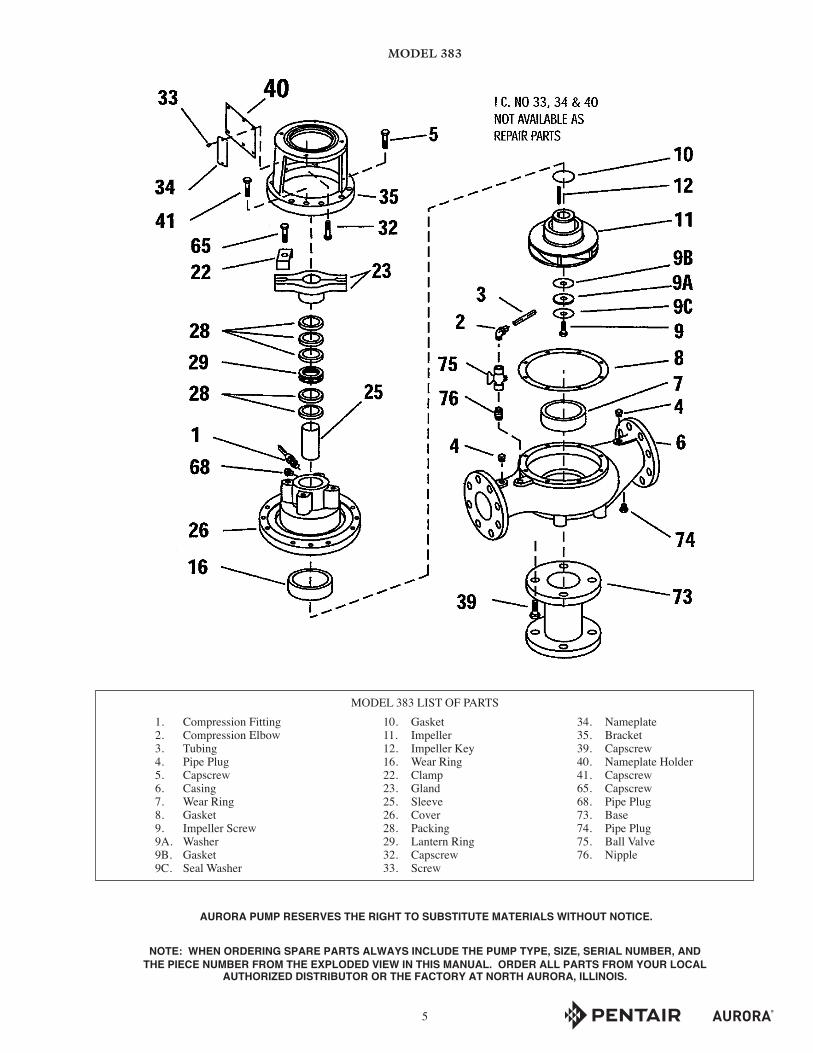
AURORA PUMP RESERVES THE RIGHT TO SUBSTITUTE MATERIALS WITHOUT NOTICE.
NOTE: WHEN ORDERING SPARE PARTS ALWAYS INCLUDE THE PUMP TYPE, SIZE, SERIAL NUMBER, AND THE PIECE NUMBER FROM THE EXPLODED VIEW IN THIS MANUAL. ORDER ALL PARTS FROM YOUR LOCAL
AUTHORIZED DISTRIBUTOR OR THE FACTORY AT NORTH AURORA, ILLINOIS.
1. Compression Fitting 2. Compression Elbow 3. Tubing 4. Pipe Plug 5. Capscrew 6. Casing 7. Wear Ring 8. Gasket 9. Impeller Screw 9A. Washer 9B. Gasket 9C. Seal Washer
10. Gasket 11. Impeller 12. Impeller Key 16. Wear Ring 22. Clamp 23. Gland 25. Sleeve 26. Cover 28. Packing 29. Lantern Ring 32. Capscrew 33. Screw
34. Nameplate 35. Bracket 39. Capscrew 40. Nameplate Holder 41. Capscrew 65. Capscrew 68. Pipe Plug 73. Base 74. Pipe Plug 75. Ball Valve 76. Nipple
MODEL 383 LIST OF PARTS

THIS PAGE INTENTIONALLY LEFT BLANK

THIS PAGE INTENTIONALLY LEFT BLANK
WARRANTYSeller warrants equipment (and its component parts) of its own manufacture against defects in materials and workmanship under normal use and service for one (1) year from the date of installation or start-up, or for eighteen (18) months after the date of shipment , whichever occurs first. Seller does not warrant accessories or components that are not manufactured by Seller; however, to the extent possible, Seller agrees to assign to Buyer its rights under the original manufacturer's warranty, without recourse to Seller. Buyer must give Seller notice in writing of any alleged defect covered by this warranty (together with all identifying details, including the serial number, the type of equipment, and the date of purchase) within thirty (30) days of the discovery of such defect during the warranty period. No claim made more than 30 days after the expiration of the warranty period shall be valid. Guarantees of performance and warranties are based on the use of original equipment manufactured (OEM) replacement parts. Seller assumes no responsibility or liability if alterations, non-authorized design modifications and/or non-OEM replacement parts are incorporated If requested by Seller, any equipment (or its component parts) must be promptly returned to Seller prior to any attempted repair, or sent to an authorized service station designated by Seller, and Buyer shall prepay all shipping expenses. Seller shall not be liable for any loss or damage to goods in transit, nor will any warranty claim be valid unless the returned goods are received intact and undamaged as a result of shipment. Repaired or replaced material returned to customer will be shipped F.O.B., Seller's factory. Seller will not give Buyer credit for parts or equipment returned to Seller, and will not accept delivery of any such parts or equipment, unless Buyer has obtained Seller's approval in writing. The warranty extends to repaired or replaced parts of Seller's manufacture for ninety (90) days or for the remainder of the original warranty period applicable to the equipment or parts being repaired or replaced, whichever is greater. This warranty applies to the repaired or replaced part and is not extended to the product or any other component of the product being repaired. Repair parts of its own manufacture sold after the original warranty period are warranted for a period of one (1) year from shipment against defects in materials and workmanship under normal use and service. This warranty applies to the replacement part only and is not extended to the product or any other component of the product being repaired. Seller may substitute new equipment or improve part(s) of any equipment judged defective without further liability. All repairs or services performed by Seller, which are not covered by this warranty, will be charged in accordance with Seller's standard prices then in effect.
THIS WARRANTY IS THE SOLE WARRANTY OF SELLER AND SELLER HEREBY EXPRESSLY DISCLAIMS AND BUYER WAIVES ALL OTHER WARRANTIES EXPRESSED, IMPLIED IN LAW OR IMPLIED IN FACT, INCLUDING ANY WARRANTIES OF MERCHANTABILITY OR FITNESS FOR A PARTICULAR PURPOSE. Seller's sole obligation under this warranty shall be, at its option, to repair or replace any equipment (or its component parts) which has a defect covered by this warranty, or to refund the purchase price of such equipment or part. Under the terms of this warranty, Seller shall not be liable for (a) consequential, collateral, special or liquidated losses or damages; (b) equipment conditions caused by normal wear and tear, abnormal conditions of use, accident, neglect, or misuse of said equipment; (c) the expense of, and loss or damage caused by, repairs or alterations made by anyone other than the Seller; (d) damage caused by abrasive materials, chemicals, scale deposits, corrosion, lightning, improper voltage, mishandling, or other similar conditions; (e) any loss, damage, or expense relating to or resulting from installation, removal or reinstallation of equipment; (f) any labor costs or charges incurred in repairing or replacing defective equipment or parts, including the cost of reinstalling parts that are repaired or replaced by Seller; (g) any expense of shipment of equipment or repaired or replacement parts; or (h) any other loss, damage or expense of any nature.
The above warranty shall not apply to any equipment which may be separately covered by any alternate or special warranties.
PERFORMANCE: In the absence of Certified Pump Performance Tests, equipment performance is not warranted or guaranteed. Performance curves and other information submitted to Buyer are approximate and no warranty or guarantee shall be deemed to arise as a result of such submittal. All testing shall be done in accordance with Seller's standard policy under Hydraulic Institute procedures.
LIABILITY LIMITATIONS: Under no circumstances shall the Seller have any liability under the Order or otherwise for liquidated damages or for collateral, consequential or special damages or for loss of profits, or for actual losses or for loss of production or progress of construction, regardless of the cause of such damages or losses. In any event, Seller's aggregate total liability under the Order or otherwise shall not exceed the contract price.
ACTS OF GOD: Seller shall in no event be liable for delays in delivery of the equipment or other failures to perform caused by fires, acts of God, strikes, labor difficulties, acts of governmental or military authorities, delays in transportation or procuring materials, or causes of any kind beyond Seller's control.
COMPLIANCE WITH LAW: Seller agrees to comply with all United States laws and regulations applicable to the manufacturing of the subject equipment. Such compliance shall include: The Fair Labor Standards Acts of 1938, as amended; Equal Employment Opportunity clauses of Executive Order 11246, as amended; Occupational Safety and Health Act of 1970 and the standards promulgated thereunder, if applicable. Since compliance with the various Federal, State, and Local laws and regulations concerning occupational health and safety, pollution or local codes are affected by the use, installation and operation of the equipment and other matters over which Seller has no control, Seller assumes no responsibility for compliance with those laws and regulations, whether by way of indemnity, warranty, or otherwise. It is incumbent upon the Buyer to specify equipment which complies with local codes and ordinances.
800 Airport RoadNorth Aurora, Illinois 60542630-859-7000www.aurorapump.com