model 85 instruction manual - thermo fisher …...thermo scientific model 85 instruction manual i...
TRANSCRIPT

Model 85 Instruction Manual
Mercury Probe115654-00 • 10Sep2018
© 2016 Thermo Fisher Scientific Inc. All rights reserved. Specifications, terms and pricing are subject to change. Not all products are available in all countries. Please consult your local sales representative for details. Thermo Fisher Scientific Air Quality Instruments 27 Forge Parkway Franklin, MA 02038 1-508-520-0430 www.thermo.com/aqi

Thermo Scientific WEEE Compliance
WEEE Compliance
This product is required to comply with the European Union’s Waste Electrical & Electronic Equipment (WEEE) Directive 2002/96/EC. It is marked with the following symbol:
Thermo Fisher Scientific has contracted with one or more recycling/disposal companies in each EU Member State, and this product should be disposed of or recycled through them. Further information on Thermo Fisher Scientific’s compliance with these Directives, the recyclers in your country, and information on Thermo Fisher Scientific products which may assist the detection of substances subject to the RoHS Directive are available at: www.thermo.com/WEEERoHS.

Thermo Scientific Model 85 Instruction Manual i
About This Manual
This manual provides information about installing, maintaining, and servicing the Model 85 Mercury Probe. It also contains important alerts to ensure safe operation and prevent equipment damage. The manual is organized into the following chapters and appendixes to provide direct access to specific operation and service information.
● Chapter 1 “Introduction” provides an overview of the product, describes the construction and operating principle of the flow assembly.
● Chapter 2 “Installation” describes how to prepare the probe enclosure, how to install the particulate deflector, and includes umbilical plumbing hookup.
● Chapter 3 “Preventive Maintenance and Servicing” provides maintenance information, replacement procedures, and a replacement parts list. It also includes contact information for product support for product information.
● Chapter 4 “System Description” provides an overview and describes the function of the system components.
● Appendix A “Warranty” is a copy of the warranty statement.

About This Manual
ii Model 85 Instruction Manual Thermo Scientific
Review the following information carefully before using the Model 85 Mercury Probe. This manual provides specific information on how to operate the extraction probe, however if the Model 85 Mercury Probe is used in a manner not specified by the manufacturer, the protection provided by the equipment may be impaired.
This manual contains important information to alert you to potential safety hazards and risks of equipment damage. Refer to the following types of alerts you may see in this manual.
Safety and Equipment Damage Alert Descriptions
Alert Description
DANGER A hazard is present that will result in death or serious personal injury if the warning is ignored. ▲
WARNING A hazard is present or an unsafe practice can result in serious personal injury if the warning is ignored. ▲
CAUTION The hazard or unsafe practice could result in minor to moderate personal injury if the warning is ignored. ▲
Equipment Damage The hazard or unsafe practice could result in property damage if the warning is ignored. ▲
Safety and Equipment Damage Alerts in this Manual
Alert Description
WARNING The service procedures in this manual are restricted to qualified service personnel only. ▲
If the equipment is operated in a manner not specified by the manufacturer, the protection provided by the equipment may be impaired. ▲
Probe is HOT. Wear appropriate PPE (personal protective equipment). ▲
Equipment Damage Do not attempt to lift the probe by the cover or other external fittings. ▲
Safety
Safety and EquipmentDamage Alerts
About This Manual
Thermo Scientific Model 85 Instruction Manual iii
The following symbol and description identify the WEEE marking used on the instrument and in the associated documentation.
Symbol Description
Marking of electrical and electronic equipment which applies to electrical and electronic equipment falling under the Directive 2002/96/EC (WEEE) and the equipment that has been put on the market after 13 August 2005. ▲
Service is available from exclusive distributors worldwide. Contact one of the phone numbers below for product support and technical information or visit us on the web at www.thermoscientific.com/aqi.
1-866-282-0430 Toll Free
1-508-520-0430 International
We continue to support our customers with advanced online resources. Our Air Quality Instruments Online Library allows our customers access to product documents and information on a constant basis.
Available 24-hours a day and seven-days a week, the online library provides quick access to information regardless of time zone or office hours.
To register for an account or log in, please visit www.thermoscientific.com/aqilibrary.
WEEE Symbol
Where to Get Help


Thermo Scientific Model 85 Instruction Manual v
Contents Introduction ........................................................................................................ 1-1
Construction of the Probe Flow Filter Assembly ................................. 1-2
Installation ......................................................................................................... 2-1 Preliminary Site Work ......................................................................... 2-1 Unpacking .......................................................................................... 2-2 Installation .......................................................................................... 2-2 Wiring ................................................................................................ 2-6 Plumbing ............................................................................................ 2-8 Thermocouple Connections .............................................................. 2-11 Power up and Verification ................................................................. 2-12
Preventive Maintenance and Servicing ....................................................... 3-1 Safety Precautions ............................................................................... 3-1 Replacement Parts List ........................................................................ 3-2 Replacement Tubing List .................................................................... 3-3 Factory Plumbing ................................................................................ 3-4 Factory Wiring .................................................................................... 3-5 Stinger Cleaning and Filter Replacement ............................................ 3-7 Converter Thermocouple Replacement ............................................. 3-11 Converter Core Assembly Replacement ............................................. 3-12 Converter Heater Replacement ......................................................... 3-13 Leak Testing...................................................................................... 3-14 Service Locations ............................................................................... 3-15
System Description .......................................................................................... 4-1 Converter Assembly ............................................................................ 4-2 Probe Flow Assembly .......................................................................... 4-2 Dilution Module ................................................................................. 4-2 Critical Dilution Orifice ...................................................................... 4-3 Probe Filter ......................................................................................... 4-3 Accumulator Tank .............................................................................. 4-3 Valves .................................................................................................. 4-3 Manifold Critical Sample Orifices ....................................................... 4-3 Stinger/Heater Assembly ..................................................................... 4-3 Oxidizer Assembly ............................................................................... 4-3 Heated Hovacal Line ........................................................................... 4-3 Isolation Valve Assembly ..................................................................... 4-3 Oxygen Sensor .................................................................................... 4-4
Chapter 1
Chapter 2
Chapter 3
Chapter 4

Contents
vi Model 85 Instruction Manual Thermo Scientific
Warranty ............................................................................................................. A-1
Appendix A

Thermo Scientific Model 85 Instruction Manual vii
Figures Figure 1–1. Model 85 Mercury Probe ................................................................. 1-2 Figure 2–1. Shipping Blocks Side View .............................................................. 2-2 Figure 2–2. Strain Reliefs with Bulkhead Fittings.............................................. 2-3 Figure 2–3. Particulate Deflector Connected ..................................................... 2-3 Figure 2–4. Mounting the Stinger Assembly to Probe ....................................... 2-4 Figure 2–5. Model 85 with Singer Assembly Installed ...................................... 2-5 Figure 2–6. Probe Wiring Diagram, ANSI Probe with Oxidizer .......................... 2-6 Figure 2–7. Probe Wiring Diagram, DIN Probe with Hovacal Connection ........ 2-7 Figure 2–8. ANSI Probe, Cross-section of Plumbing with Oxidizer Assembly .. 2-8 Figure 2–9. DIN Probe, Cross-section of Plumbing with Hovacal Tubing ....... 2-10 Figure 2–10. Thermocouple Connections ......................................................... 2-11 Figure 3–1. Removal of Dilution Filter ................................................................ 3-8 Figure 3–2. Probe Flow Disassembly ................................................................. 3-8 Figure 3–3. Probe with Dilution Module Assembly Removed ........................... 3-9 Figure 3–4. O-ring Assembly with Lubricant .................................................... 3-10 Figure 3–5. Converter Assembly Replacements .............................................. 3-11 Figure 3–6. Flow Assembly Leak Test .............................................................. 3-15 Figure 4–1. Model 85 Mercury Probe ................................................................. 4-2

Thermo Scientific Model 85 Instruction Manual ix
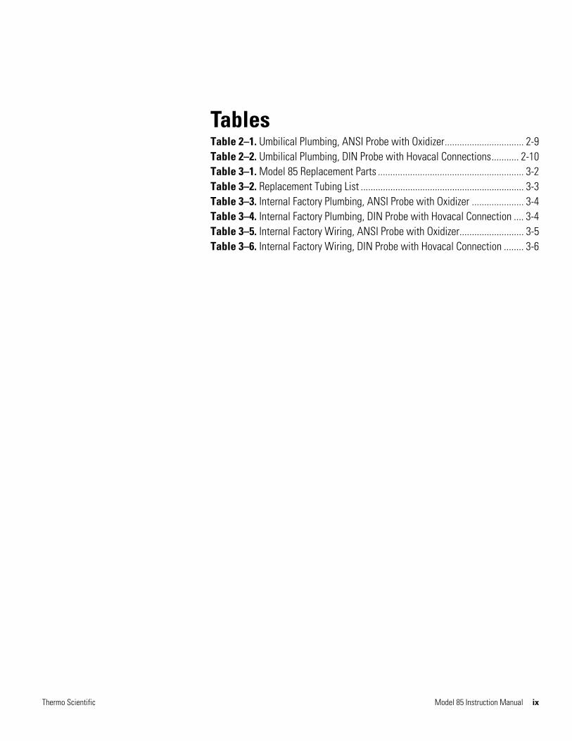
Tables Table 2–1. Umbilical Plumbing, ANSI Probe with Oxidizer ................................ 2-9 Table 2–2. Umbilical Plumbing, DIN Probe with Hovacal Connections ........... 2-10 Table 3–1. Model 85 Replacement Parts ........................................................... 3-2 Table 3–2. Replacement Tubing List .................................................................. 3-3 Table 3–3. Internal Factory Plumbing, ANSI Probe with Oxidizer ..................... 3-4 Table 3–4. Internal Factory Plumbing, DIN Probe with Hovacal Connection .... 3-4 Table 3–5. Internal Factory Wiring, ANSI Probe with Oxidizer .......................... 3-5 Table 3–6. Internal Factory Wiring, DIN Probe with Hovacal Connection ........ 3-6


Thermo Scientific Model 85 Instruction Manual 1-1
Chapter 1
Introduction
The Model 85 Mercury (Hg) Mercury Probe is configured as one component of Thermo Fisher Scientific’s integrated Hg Continuous Emission Monitoring System (CEMS). Thermo Fisher Scientific’s Mercury Freedom™ System is comprised of a Hg Analyzer (Model 80i), a Hg Calibrator (Model 81i), a Hg Probe Controller (Model 82i), and a Hg Extraction Probe (Model 85) along with additional peripheral components, e.g., zero air supply, umbilical, instrument rack, etc. The Model 85 Mercury Probe, with built-in dilution, has been designed specifically to monitor gaseous Hg emissions from coal-fired power plants and cement kiln factories.
The probe is housed in an aluminum enclosure and is designed to meet NEMA 4X specifications. To prevent sample condensation, key elements (Dilution Module and Bypass Pump) have been mounted between heated aluminum blocks that can be maintained at temperatures as high as 250 °C.
The probe enclosure also houses an accumulator tank for back purging of the stinger (blow back). External to the enclosure is a section with the electrical connections and solenoids for stinger blow back, cal gas, and chlorine gas (Cl2), (if applicable).
A special 4-inch adapted mounting flange has been supplied with the Stinger Assembly for installation onto the port of the stack or duct for the U.S. and China market. A DIN flange is supplied for E.U. applications.
Clean dry pressurized (~90 psig) air feeds two electronic pressure regulators in the Model 82i (Figure 1–1), which adjust and maintain output pressure
to the Model 85 Probe Eductor and Blow Back pneumatics. Pressurized (~65 psig) Hg-free zero air feeds a third electronic regulator in the Model 82i, which adjusts and maintains dilution air pressure to the Model 85 Probe Dilution Module. Also contained within the Model 82i are three electronic pressure transducers associated with the individual regulators, as well as an electronic vacuum transducer monitoring the Dilution Module vacuum in the Model 85.
The Model 85 Mercury Probe is an extraction probe which includes a particulate filter, built in dilution module and high temperature thermal converter for reducing oxidized Hg to elemental Hg for subsequent analysis by the Model 80i Mercury Analyzer.

Introduction Construction of the Probe Flow Filter Assembly
1-2 Model 85 Instruction Manual Thermo Scientific
The Model 82i provides both 220 and 110 AC voltage to the Model 85 Probe. 220 VAC powers the probe’s stinger heater and probe flow heaters. 110 VAC powers the Total Hg converter as well as four (4) probe solenoid valves for Cal/Zero gas, Stinger blow back, and Cl2.
Figure 1–1. Model 85 Mercury Probe
The probe filter assembly contains a porous filter element. This filter element is a diffusion-bonded, sintered seamless porous tube with a 0.5 micron grade.
A filter housing tube surrounds the tubular element, creating a minimum-volume annular plenum for sample collection. A high-efficiency gas eductor induces axial flow through the filter element.
The sample is then pulled through an orifice by the dilution assembly. The dilution sample is directed to the manifold that has connections to the elemental umbilical tubing, the converter and HgT umbilical tubing, and a dump for the excess diluted sample.
Construction of theProbe Flow Filter
Assembly

Thermo Scientific Model 85 Instruction Manual 2-1
Chapter 2
Installation
The installation of Model 85 involves several steps:
● “Preliminary Site Work” on page 2-1
● “Unpacking” on page 2-2
● “Installation” on page 2-2
● “Wiring” on page 2-6
● “Plumbing” on page 2-8
● “Thermocouple Connections” on page 2-11
The Model 85 Mercury Probe is a mercury extraction probe designed to be a direct replacement for the Model 83i Extraction Probe. The flange is 4-inch ANSI, or Euro DN65/PN6 (150 lb.), and the power and air requirements are the same as the existing system. If you are replacing an existing probe, such as the 83i probe, please perform the following preliminary site work steps.
WARNING Do not attempt to lift the probe by the cover or other external fittings. ▲
1. It is critical that the existing system that is going to be connected to the Model 85 is operating correctly, with proper power and air supply.
2. In the 80i menu turn OFF Component power to the Probe, Converter, Oxidizer, and Stinger.
3. Shut OFF sample pump at instrument rack.
4. Shut down 82i power and remove 85 probe cover.
5. Close the chlorine cylinder valve and disconnect the line from the probe if applicable (if probe contains the oxidizer option).
Preliminary SiteWork

Installation Unpacking
2-2 Model 85 Instruction Manual Thermo Scientific
6. Disconnect all electrical and pneumatic connections between the umbilical and the probe.
7. Remove probe from stack flange.
Use the following procedure to unpack the probe.
1. Remove foam block from inside of probe.
Figure 2–1. Shipping Blocks Side View
Use the following procedure to install the probe.
1. Install umbilical strain relief (2.9-inch). If using a dual umbilical, install the optional 2.9-inch strain relief. If using a single umbilical, install the 2.9-inch plug that came in the accessory kit.
Install 1/4-inch bulkheads. Connect the 11-inch PTFE tubing from chlorine valve to chlorine bulkhead. Connect 19-inch tubing from fitting on left side of probe manifold to vent bulkhead.
Unpacking
Installation
Installation Installation
Thermo Scientific Model 85 Instruction Manual 2-3
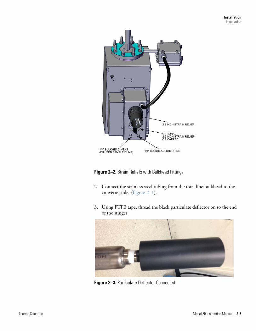
Figure 2–2. Strain Reliefs with Bulkhead Fittings
2. Connect the stainless steel tubing from the total line bulkhead to the converter inlet (Figure 2–1).
3. Using PTFE tape, thread the black particulate deflector on to the end of the stinger.
Figure 2–3. Particulate Deflector Connected

Installation Installation
2-4 Model 85 Instruction Manual Thermo Scientific
4. Install stinger assembly first into the stack flange, ensure electrical junction box is on the left as you face the stack. Ensure gasket is installed between stinger flange and stack flange, attach stinger assembly to stack, and tighten bolts evenly so the gasket is sealed flat.
5. Remove nuts and washers from the four bolts facing away from stack, mount probe onto bolts with blue gasket. It is critical to make sure the hole in the blue gasket is at the 12 o’clock position or the probe will not work properly (bypass return to stack). Add lock washers and nuts inside of probe. It is very important to tighten the nut evenly so that the gasket seals all the way around the flange.
Figure 2–4. Mounting the Stinger Assembly to Probe
Gasket between Probe and Stinger
Installation Installation
Thermo Scientific Model 85 Instruction Manual 2-5
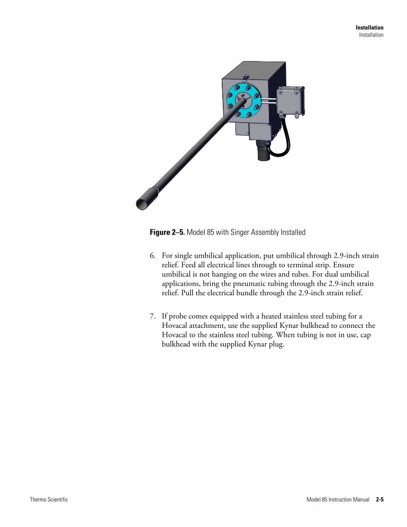
Figure 2–5. Model 85 with Singer Assembly Installed
6. For single umbilical application, put umbilical through 2.9-inch strain relief. Feed all electrical lines through to terminal strip. Ensure umbilical is not hanging on the wires and tubes. For dual umbilical applications, bring the pneumatic tubing through the 2.9-inch strain relief. Pull the electrical bundle through the 2.9-inch strain relief.
7. If probe comes equipped with a heated stainless steel tubing for a Hovacal attachment, use the supplied Kynar bulkhead to connect the Hovacal to the stainless steel tubing. When tubing is not in use, cap bulkhead with the supplied Kynar plug.

Installation Wiring
2-6 Model 85 Instruction Manual Thermo Scientific
Use the following wiring diagram to connect the Model 85.
1. Wire stinger and umbilical according to Figure 2–6 and Figure 2–7. Note there will be some unused wires. These should be individually wrapped with electrical tape and secured to the bundle away from ground.
2. Connect Probe, Oxidizer, and Converter Thermocouples. Connect all probe heaters and valves according to Figure 2–8.
Figure 2–6. Probe Wiring Diagram, ANSI Probe with Oxidizer
Wiring
Installation Wiring
Thermo Scientific Model 85 Instruction Manual 2-7
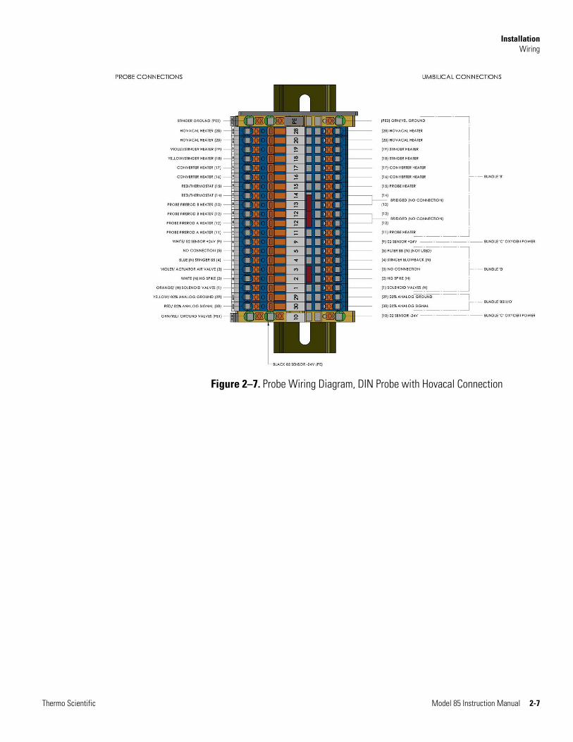
Figure 2–7. Probe Wiring Diagram, DIN Probe with Hovacal Connection

Installation Plumbing
2-8 Model 85 Instruction Manual Thermo Scientific
Use the following procedure to connect PFA tubing to probe.
1. Feed tubes 1 (Total Hg), 2 (Elemental Hg), 5 (Eductor Air), 6 (Vacuum) and 7 (Dilution air) up through the slot on the bottom of the Model 85 chassis. Attach according to the following plumbing diagram (Figure 2–8).
Figure 2–8. ANSI Probe, Cross-section of Plumbing with Oxidizer Assembly
2. Attach tube 3 (3/8-inch Hg Cal Gas) to the Hg solenoid valve. Attach tube 8 (1/4-inch Blowback) to the accumulator tank.
3. Connect Chlorine line to Chlorine bulk head (installed on bottom of probe). Do not confuse with diluted sample dump bulkhead. Internally, the chlorine bulkhead is connected to the valve assembly.
Plumbing
Installation Plumbing
Thermo Scientific Model 85 Instruction Manual 2-9
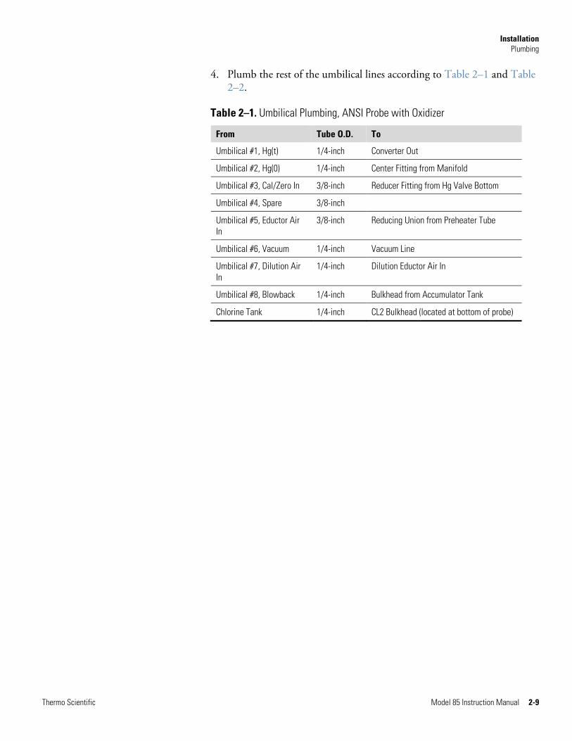
4. Plumb the rest of the umbilical lines according to Table 2–1 and Table 2–2.
Table 2–1. Umbilical Plumbing, ANSI Probe with Oxidizer
From Tube O.D. To
Umbilical #1, Hg(t) 1/4-inch Converter Out
Umbilical #2, Hg(0) 1/4-inch Center Fitting from Manifold
Umbilical #3, Cal/Zero In 3/8-inch Reducer Fitting from Hg Valve Bottom
Umbilical #4, Spare 3/8-inch
Umbilical #5, Eductor Air In
3/8-inch Reducing Union from Preheater Tube
Umbilical #6, Vacuum 1/4-inch Vacuum Line
Umbilical #7, Dilution Air In
1/4-inch Dilution Eductor Air In
Umbilical #8, Blowback 1/4-inch Bulkhead from Accumulator Tank
Chlorine Tank 1/4-inch CL2 Bulkhead (located at bottom of probe)

Installation Plumbing
2-10 Model 85 Instruction Manual Thermo Scientific
Figure 2–9. DIN Probe, Cross-section of Plumbing with Hovacal Tubing
Table 2–2. Umbilical Plumbing, DIN Probe with Hovacal Connections
From Tube O.D. To
Umbilical #1, Hg(t) 1/4-inch Converter Out
Umbilical #2, Hg(0) 1/4-inch Center Fitting from Manifold
Umbilical #3,Cal/Zero In 3/8-inch Reducer Fitting from Hg Valve Bottom
Umbilical #4, Spare 3/8-inch
Umbilical #5, Eductor Air In
3/8-inch Reducing Union from Preheater Tube
Umbilical #6, Vacuum 1/4-inch Vacuum Line
Umbilical #7, Dilution Air In
1/4-inch Dilution Eductor Air In
Umbilical #8, Blowback 1/4-inch Bulkhead from Accumulator Tank

Installation Thermocouple Connections
Thermo Scientific Model 85 Instruction Manual 2-11
If required, use the following procedure to assemble thermocouples (Figure 2–10). Using a medium or small size slotted screw driver, remove the thermocouple connector cover.
1. Loosen the compression screws inside the connector.
2. Attach the red umbilical lead labeled TC 1 to the - side of the connector by sliding the stripped lead through the connector grommet between the metal plates and tightening the screw.
3. Repeat step 3 for the yellow umbilical lead into the + side.
4. Reinstall cover.
5. Repeat above for TC 2.
Figure 2–10. Thermocouple Connections
ThermocoupleConnections
Grommet Compress Screws onto T.C. wires

Installation Power up and Verification
2-12 Model 85 Instruction Manual Thermo Scientific
Use the following procedure to power up and verify connection to the probe.
1. Turn power ON to the 82i.
2. Turn On sample pump and ensure that the Chamber pressure is below 90 mmHg.
3. In the 80i menu ensure all temperatures in the probe are reading near ambient temperatures.
Note System gas mode will be in blow back until probe temperature reaches the setpoint. ▲
4. In the 80i menu turn on Stinger component power.
5. In the 80i menu turn on Probe component power (monitor temperature to ensure it reaches the setpoint of 220 °C).
6. In the 80i menu turn on Converter component power (monitor temperature to ensure it reaches the setpoint of 760 °C).
7. In the 80i menu turn on Oxidizer component power (monitor temperature to ensure it reaches the setpoint of 400 °C).
If the probe is equipped with the optional heated Hovacal Line instead of an oxidizer, set the temperature setpoint to 250 °C. This will heat the Hovacal tubing to the specified temperature.
8. Ensure probe covers are on.
Note Heater circuits are powered on one at a time so that proper thermocouple and heater connection may be verified. ▲
9. Check Probe pressures to ensure proper operation. (Venturi and Orifice pressure are not used in Model 85.)
a. Eductor set and reading to 10 psig
b. Dilution Air Pressure set and reading 30–50 psig
Power up andVerification

Installation Power up and Verification
Thermo Scientific Model 85 Instruction Manual 2-13
c. Dilution Vacuum reading >19 in Hg
d. Blowback Pressure set and reading 60 psig
X CONCENTRATION W HgO 10.00 µg/m3 Hg2+ 10.00 µg/m3 Hgt 10.00 µg/m3 SAMPLE 12:34 1 PRESSURE PROBE: >VENTURI ORIFICE DILUTION BLOW BACK EDUCTOR VACUUM GMODE AVG DIAGS ALARM
10. After burn in conditioning overnight, zero and calibrate the system. Use 15-minute zero and 15-minute span at 8.1 ug/m3. See 80i Analyzer Manual and System Manual.
11. Set the 80i to perform an automatic zero and span calibration every 24 hours.


Thermo Scientific Model 85 Instruction Manual 3-1
Chapter 3
Preventive Maintenance and Servicing
This chapter includes the following maintenance information and replacement procedures that should be performed on the Model 85 to ensure proper operation. All plumbing type replacements should be followed-up with a leak test. For details, see the following:
● “Safety Precautions” on page 3-1
● “Replacement Parts List” on page 3-2
● “Factory Plumbing” on page 3-4
● “Replacement Tubing List” on page 3-3
● “Factory Wiring” on page 3-5
● “Stinger Cleaning and Filter Replacement” on page 3-7
● “Converter Thermocouple Replacement” on page 3-11
● “Converter Core Assembly Replacement” on page 3-12
● “Converter Heater Replacement” on page 3-13
● “Leak Testing” on page 3-14
● “Service Locations” on page 3-15
Read the safety precautions before beginning any procedures in this chapter.
WARNING The service procedures in this manual are restricted to qualified service representatives. ▲
If the equipment is operated in a manner not specified by the manufacturer, the protection provided by the equipment may be impaired. ▲
Safety Precautions
Preventive Maintenance and Servicing Replacement Parts List
3-2 Model 85 Instruction Manual Thermo Scientific
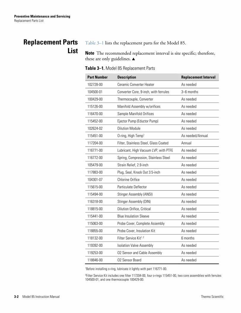
Table 3–1 lists the replacement parts for the Model 85.
Note The recommended replacement interval is site specific; therefore, these are only guidelines. ▲
Table 3–1. Model 85 Replacement Parts
Part Number Description Replacement Interval
102728-00 Ceramic Converter Heater As needed
104500-01 Converter Core, 9-inch, with ferrules 3–6 months
100429-00 Thermocouple, Converter As needed
115126-00 Manifold Assembly w/orifices As needed
116470-00 Sample Manifold Orifices As needed
115452-00 Ejector Pump (Eductor Pump) As needed
102624-02 Dilution Module As needed
115451-00 O-ring, High Temp1 As needed/Annual
117204-00 Filter, Stainless Steel, Glass Coated Annual
116771-00 Lubricant, High Vacuum LVP, with PTFE As needed
116772-00 Spring, Compression, Stainless Steel As needed
105479-00 Strain Relief, 2.9-inch As needed
117883-00 Plug, Seal, Knock Out 3.5-inch As needed
104301-07 Chlorine Orifice As needed
115615-00 Particulate Deflector As needed
115494-00 Stinger Assembly (ANSI) As needed
116318-00 Stinger Assembly (DIN) As needed
118815-00 Dilution Orifice, Critical As needed
115441-00 Blue Insulation Sleeve As needed
115063-00 Probe Cover, Complete Assembly As needed
118855-00 Probe Cover, Insulation Kit As needed
118132-00 Filter Service Kit1, 2 6 months
119392-00 Isolation Valve Assembly As needed
119253-00 O2 Sensor and Cable Assembly As needed
118846-00 O2 Sensor Board As needed
1Before installing o-ring, lubricate it lightly with part 116771-00.
2Filter Service Kit includes one filter 117204-00, four o-rings 115451-00, two core assemblies with ferrules 104500-01, and one thermocouple 100429-00.
Replacement PartsList
Preventive Maintenance and Servicing Replacement Tubing List
Thermo Scientific Model 85 Instruction Manual 3-3
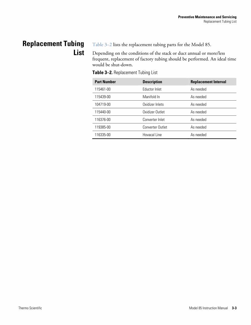
Table 3–2 lists the replacement tubing parts for the Model 85.
Depending on the conditions of the stack or duct annual or more/less frequent, replacement of factory tubing should be performed. An ideal time would be shut-down.
Table 3–2. Replacement Tubing List
Part Number Description Replacement Interval
115461-00 Eductor Inlet As needed
115439-00 Manifold In As needed
104719-00 Oxidizer Inlets As needed
115440-00 Oxidizer Outlet As needed
116376-00 Converter Inlet As needed
119385-00 Converter Outlet As needed
116335-00 Hovacal Line As needed
Replacement TubingList

Preventive Maintenance and Servicing Factory Plumbing
3-4 Model 85 Instruction Manual Thermo Scientific
Table 3–3 and Table 3–4 lists the internal factory plumbing.
Table 3–3. Internal Factory Plumbing, ANSI Probe with Oxidizer
From Tubing, Length To
CL2 Bulkhead 1/4” PFA, 11” CL2 Valve, Bottom
Manifold P3, Dump 1/4” PFA, 19” Vent Port, Thru Slot 2
Accumulator Tank Tee, Bottom 1/4” PFA, 13” BB Sting Valve, Bottom
Accumulator Tank Tee, Middle 1/4” PFA, 15-3/4” Actuator Air Valve, Side (3-way)
Actuator Air Valve, Top (NO) 1/4” PFA, 15” Isolation Valve, Right
Actuator Air Valve, Bottom (NC) 1/4” PFA, 28” Isolation Valve, Left
Isolation Valve 3/8” PFA, 6” Stack Return
BB Sting Valve, Top 1/4” PFA, 14.5” Mantle Port Tee, Top
Hg Valve, Top 1/4” PFA, 18.375” Oxidizer, Right
CL2 Valve, Top 1/4” PFA, 18” Oxidizer, Left
Oxidizer Out, Center P/N: 115440-00 Mantle Port Tee, Bottom
Manifold, P1 P/N: 116376-00 (ref)
Converter Inlet
Table 3–4. Internal Factory Plumbing, DIN Probe with Hovacal Connection
From Tubing, Length To
O2 Sensor, Thru Slot 2 1/4” PFA, 17” Manifold, P3
Accumulator Tank Tee, Bottom 1/4” PFA, 13” BB Sting Valve, Bottom
Accumulator Tank Tee, Middle 1/4” PFA, 15-3/4” Actuator Air Valve, Side
Actuator Air Valve, Top 1/4” PFA, 15” Isolation Valve, Right
Actuator Air Valve, Bottom 1/4” PFA, 28” Isolation Valve, Left
Isolation Valve 3/8” PFA, 6” Stack Return
BB Sting Valve, Top 1/4” PFA, 14.5” Mantle Port Cross, Top
Hg Valve, Top 1/4” PFA, 18” Enclosure Bulkhead
Manifold P1 P/N: 116376-00 (ref)
Converter Inlet
Hg Enclosure Bulkhead 1/4” PFA, 8” Hovacal Inlet
Factory Plumbing
Preventive Maintenance and Servicing Factory Wiring
Thermo Scientific Model 85 Instruction Manual 3-5
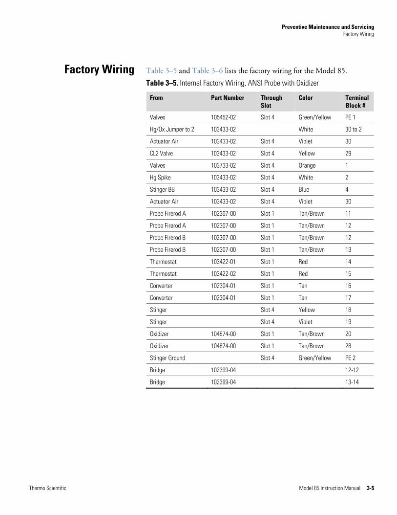
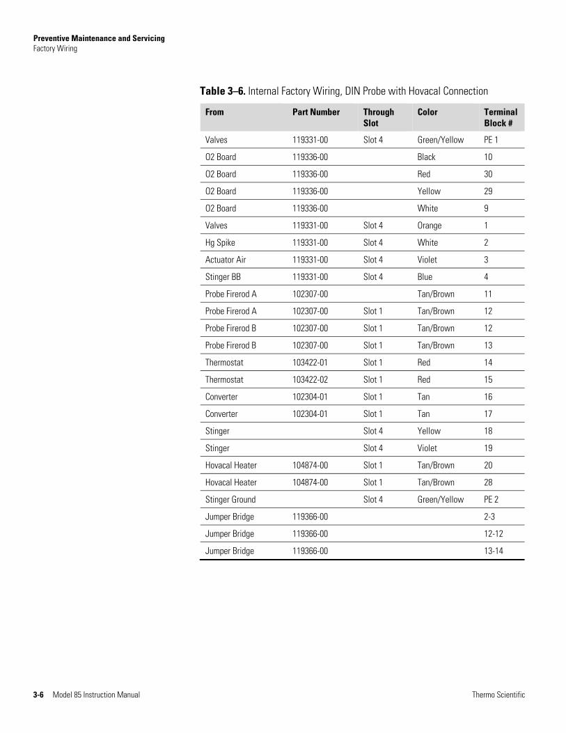
Table 3–5 and Table 3–6 lists the factory wiring for the Model 85.
Table 3–5. Internal Factory Wiring, ANSI Probe with Oxidizer
From Part Number Through Slot
Color Terminal Block #
Valves 105452-02 Slot 4 Green/Yellow PE 1
Hg/Ox Jumper to 2 103433-02 White 30 to 2
Actuator Air 103433-02 Slot 4 Violet 30
CL2 Valve 103433-02 Slot 4 Yellow 29
Valves 103733-02 Slot 4 Orange 1
Hg Spike 103433-02 Slot 4 White 2
Stinger BB 103433-02 Slot 4 Blue 4
Actuator Air 103433-02 Slot 4 Violet 30
Probe Firerod A 102307-00 Slot 1 Tan/Brown 11
Probe Firerod A 102307-00 Slot 1 Tan/Brown 12
Probe Firerod B 102307-00 Slot 1 Tan/Brown 12
Probe Firerod B 102307-00 Slot 1 Tan/Brown 13
Thermostat 103422-01 Slot 1 Red 14
Thermostat 103422-02 Slot 1 Red 15
Converter 102304-01 Slot 1 Tan 16
Converter 102304-01 Slot 1 Tan 17
Stinger Slot 4 Yellow 18
Stinger Slot 4 Violet 19
Oxidizer 104874-00 Slot 1 Tan/Brown 20
Oxidizer 104874-00 Slot 1 Tan/Brown 28
Stinger Ground Slot 4 Green/Yellow PE 2
Bridge 102399-04 12-12
Bridge 102399-04 13-14
Factory Wiring
Preventive Maintenance and Servicing Factory Wiring
3-6 Model 85 Instruction Manual Thermo Scientific
Table 3–6. Internal Factory Wiring, DIN Probe with Hovacal Connection
From Part Number Through Slot
Color Terminal Block #
Valves 119331-00 Slot 4 Green/Yellow PE 1
O2 Board 119336-00 Black 10
O2 Board 119336-00 Red 30
O2 Board 119336-00 Yellow 29
O2 Board 119336-00 White 9
Valves 119331-00 Slot 4 Orange 1
Hg Spike 119331-00 Slot 4 White 2
Actuator Air 119331-00 Slot 4 Violet 3
Stinger BB 119331-00 Slot 4 Blue 4
Probe Firerod A 102307-00 Tan/Brown 11
Probe Firerod A 102307-00 Slot 1 Tan/Brown 12
Probe Firerod B 102307-00 Slot 1 Tan/Brown 12
Probe Firerod B 102307-00 Slot 1 Tan/Brown 13
Thermostat 103422-01 Slot 1 Red 14
Thermostat 103422-02 Slot 1 Red 15
Converter 102304-01 Slot 1 Tan 16
Converter 102304-01 Slot 1 Tan 17
Stinger Slot 4 Yellow 18
Stinger Slot 4 Violet 19
Hovacal Heater 104874-00 Slot 1 Tan/Brown 20
Hovacal Heater 104874-00 Slot 1 Tan/Brown 28
Stinger Ground Slot 4 Green/Yellow PE 2
Jumper Bridge 119366-00 2-3
Jumper Bridge 119366-00 12-12
Jumper Bridge 119366-00 13-14
Preventive Maintenance and Servicing Stinger Cleaning and Filter Replacement
Thermo Scientific Model 85 Instruction Manual 3-7
Use the following procedure to replace the filter and o-ring (Figure 3–2).
Equipment Required:
O-ring/O-ring lubricant
1/2-inch bore brush
Wooden stick or dowel
Pliers
WARNING The service procedures in this manual are restricted to qualified service representatives. ▲
Note Every time you open the dilution module/filter nut, you will have to replace the o-ring seal. ▲
1. Record Dilution and Eductor pressures.
2. In the 80i menu turn OFF Probe component power, the sample pump and set the dilution air and eductor air down to 0 psi. (This is important.) The system must be in stinger blowback during this procedure.
WARNING Probe is HOT. Wear appropriate PPE (personal protective equipment). ▲
3. Remove isolation valve from top of educator.
4. Open the four clamps that hold the top and bottom aluminum heater blocks together.
5. Remove top aluminum block and put off to the side. Be careful of the thermocouple wire.
6. Loosen the grooved nut that seals the dilution module to the sample weldment.
Stinger Cleaning and Filter Replacement

Preventive Maintenance and Servicing Stinger Cleaning and Filter Replacement
3-8 Model 85 Instruction Manual Thermo Scientific
Figure 3–1. Removal of Dilution Filter
7. Remove PTFE tubing from Dilution Air In.
8. Remove PTFE tubing from Vacuum Line.
9. Disconnect 1/4-inch glass-coated tube from the orifice manifold block and pull dilution module backward (be careful to not bend the 1/8-inch vacuum line).
Figure 3–2. Probe Flow Disassembly
Critical Orifice (Dilution OrificeO-ring
Sintered Filter
Dilution Module
Grooved Nut Sample Weldment
Vacuum Line
Dilution Assembly Grooved Nut
Dilution Air In
Glass Coated Tubeto Manifold

Preventive Maintenance and Servicing Stinger Cleaning and Filter Replacement
Thermo Scientific Model 85 Instruction Manual 3-9
10. If cleaning the filter, loosen the nut that is closest to the filter and separate the filter from the dilution module. The union fitting that is between the dilution module and the filter is the dilution orifice and should not be removed from the dilution module.
11. With the filter and dilution module removed you should be able to clean out the stinger tube with 1/2-inch bore brush (it is open all the way to the stack).
Figure 3–3. Probe with Dilution Module Assembly Removed
12. Using a wooden stick or dowel, clean any o-ring particles out of the opening before replacing the filter and dilution module back into the sample weldment. Take care not to scratch the glass coating.
13. Apply high vacuum grease (116771-00) lightly and evenly onto o-ring (115451-00). Assembly as shown in Figure 3–4.
Note If entire flow assembly was removed, perform leak test. ▲
Preventive Maintenance and Servicing Stinger Cleaning and Filter Replacement
3-10 Model 85 Instruction Manual Thermo Scientific
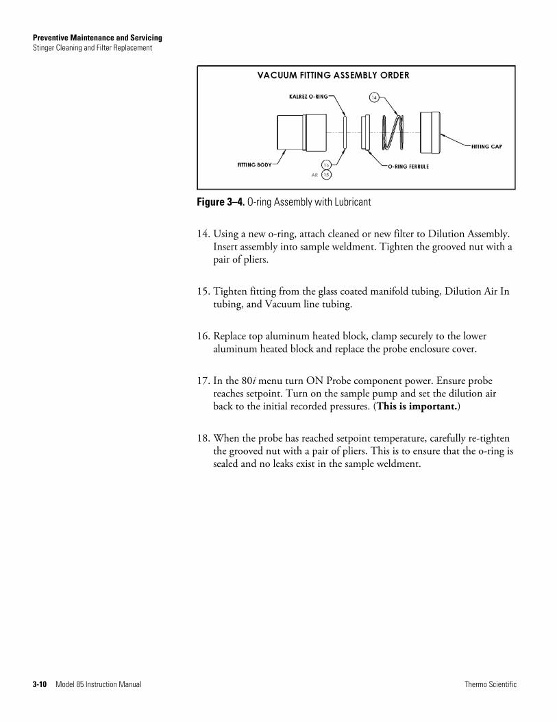
Figure 3–4. O-ring Assembly with Lubricant
14. Using a new o-ring, attach cleaned or new filter to Dilution Assembly. Insert assembly into sample weldment. Tighten the grooved nut with a pair of pliers.
15. Tighten fitting from the glass coated manifold tubing, Dilution Air In tubing, and Vacuum line tubing.
16. Replace top aluminum heated block, clamp securely to the lower aluminum heated block and replace the probe enclosure cover.
17. In the 80i menu turn ON Probe component power. Ensure probe reaches setpoint. Turn on the sample pump and set the dilution air back to the initial recorded pressures. (This is important.)
18. When the probe has reached setpoint temperature, carefully re-tighten the grooved nut with a pair of pliers. This is to ensure that the o-ring is sealed and no leaks exist in the sample weldment.

Preventive Maintenance and Servicing Converter Thermocouple Replacement
Thermo Scientific Model 85 Instruction Manual 3-11
Use the following procedure to replace the converter thermocouple (Figure 3–5).
Equipment Required:
Thermocouple
WARNING The service procedures in this manual are restricted to qualified service representatives. ▲
1. Unplug thermocouple from umbilical hookup.
2. Snip any tie wraps holding the thermocouple in place.
3. Replace thermocouple and reassemble in reverse order.
Figure 3–5. Converter Assembly Replacements
ConverterThermocouple
Replacement
Converter CoreAssembly
Insulating Cloth
Ceramic Heater
Thermocouple
Preventive Maintenance and Servicing Converter Core Assembly Replacement
3-12 Model 85 Instruction Manual Thermo Scientific
Use the following procedure to replace the converter core assembly.
Equipment Required:
Converter core assembly
Open-end wrenches, 11/16-inch and 15/16-inch
WARNING The service procedures in this manual are restricted to qualified service representatives. ▲
1. Allow converter to cool.
2. Using a 15/16-inch and 11/16-inch open end wrench, loosen fittings compressed on core assembly.
3. Slide out core assembly.
4. Install new core and reassemble in reverse order. Use new PFA ferrules, 105325-00.
Converter Core Assembly
Replacement

Preventive Maintenance and Servicing Converter Heater Replacement
Thermo Scientific Model 85 Instruction Manual 3-13
Use the following procedure to replace the heater (Figure 3–5).
Equipment Required:
Ceramic heater
Open-end wrenches, 11/16-inch and 15/16-inch
Nut driver, 11/32-inch
Phillips screwdriver
WARNING The service procedures in this manual are restricted to qualified service representatives. ▲
1. Allow converter to cool.
2. Using an 11/16-inch and 15/16-inch open end wrench, loosen fittings compressed on core assembly.
3. Remove core assembly.
4. Disconnect wiring in upper assembly. Refer to Table 3–5 on page 3-5.
5. Using a Phillips head screwdriver, remove four screws mounting the converter assembly to the probe enclosure.
6. Using a Phillips head screwdriver, remove six screws holding converter cover in place.
7. Install new heater and reassemble in reverse order.
Converter Heater Replacement

Preventive Maintenance and Servicing Leak Testing
3-14 Model 85 Instruction Manual Thermo Scientific
The Flow Assembly can be tested for leaks by plugging all the openings except two. A vacuum gauge and a pump will be connected to the fittings that are left open.
Use the following procedure to perform a leak test.
Equipment Required:
Stainless steel or PTFE caps, 1/2-inch, 3/4-inch, and 1/4-inch
Pump
Ball valve, 1/4-inch
Vacuum gauge
WARNING The service procedures in this manual are restricted to qualified service representatives. ▲
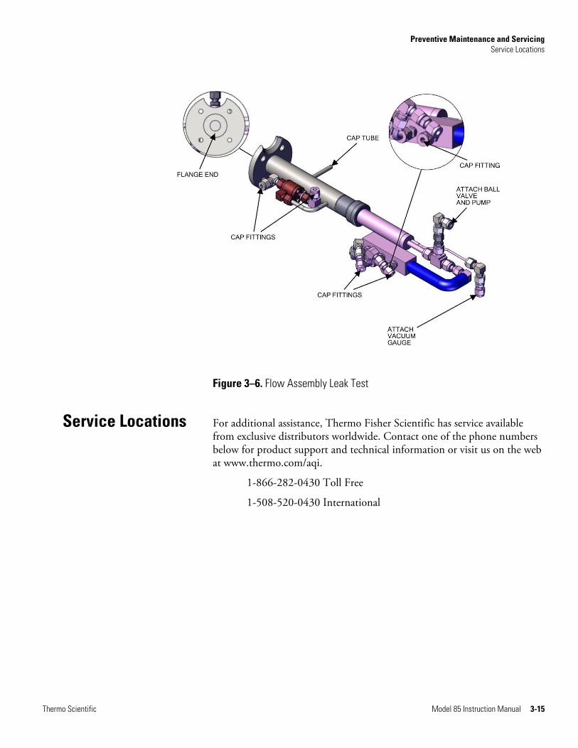
1. Plug the flange end of the flow assembly. Or mount the flange to the gasket in order to seal the open end.
2. Using 6 plugs, plug (cap) the fittings as shown in Figure 3–6.
3. Connect a vacuum gauge to the elbow on the vacuum port. Take care not to damage the 1/8-inch tubing.
4. Connect a vacuum pump (such as Welch pump 2561 or equivalent) to a ball valve. Attach the ball valve in line with the Dilution Air Input port.
5. Open the ball valve and turn the pump on.
6. After about 15 seconds, close the ball valve. Turn pump off and observe the vacuum gauge.
The vacuum gauge should remain constant. If leaks are present, the vacuum gauge will approach zero (a leak rate of 0.25 in/Hg per 5 minute period is acceptable).
Leak Testing
Preventive Maintenance and Servicing Service Locations
Thermo Scientific Model 85 Instruction Manual 3-15
Figure 3–6. Flow Assembly Leak Test
For additional assistance, Thermo Fisher Scientific has service available from exclusive distributors worldwide. Contact one of the phone numbers below for product support and technical information or visit us on the web at www.thermo.com/aqi.
1-866-282-0430 Toll Free
1-508-520-0430 International
Service Locations


Thermo Scientific Model 85 Instruction Manual 4-1
Chapter 4
System Description
The System Description chapter provides and overview of the Model 85 describes the function of the system components and provides a typical system plumbing hookup per the following:
● “Converter Assembly” on page 4-2
● “Probe Flow Assembly” on page 4-2
● “Dilution Module” on page 4-2
● “Critical Dilution Orifice” on page 4-3
● “Probe Filter” on page 4-3
● “Accumulator Tank” on page 4-3
● “Valves” on page 4-3
● “Manifold Critical Sample Orifices” on page 4-3
● “Stinger/Heater Assembly” on page 4-3
● “Oxidizer Assembly” on page 4-3
● “Heated Hovacal Line” on page 4-3
The Model 85 Mercury Probe is a mercury extraction probe designed for use in the Thermo Freedom continuous emissions monitoring system. The probe weighs approximately sixty-five pounds and consists of a 3-inch mounting flange, and isolated electrical and pneumatic compartments.
The pneumatic compartment houses an Hg cal/zero valve, stinger blow back valve, Cl2 valve, and a Phoenix™ DIN-rail block for all electrical connections.
The main compartment consists of a probe flow assembly, converter assembly, and a 2.9-inch strain relief for the umbilical cord. An additional 2.9-inch strain relief is available for applications using dual umbilical configurations.
The probe flow assembly consists of a particulate filter, critical orifice, bypass pump assembly, and dilution eductor assembly, all of which are entombed in heated aluminum blocks. The manifold inlet is attached to

System Description Converter Assembly
4-2 Model 85 Instruction Manual Thermo Scientific
the diluted sample line of the dilution eductor. The manifold has three outlets. The left outlet is vented to a dump, the middle outlet contains an orifice which connects to the Elemental line, and the right outlet contains an orifice and connects to the Converter inlet tubing.
Figure 4–1. Model 85 Mercury Probe
Operating at 760 °C, the converter disassociates the salts and oxides of mercury to give elemental mercury. This, along with the elemental already passing through, gives the total mercury of the sample.
This assembly, which is heated, contains all of the sample inlet components. It keeps the components at or near 220 °C.
The dilution module dilutes the sample with zero air and delivers it to the analyzer via the scrubber or converter and heated umbilical cord.
Converter Assembly
Probe FlowAssembly
Dilution Module
System Description Critical Dilution Orifice
Thermo Scientific Model 85 Instruction Manual 4-3
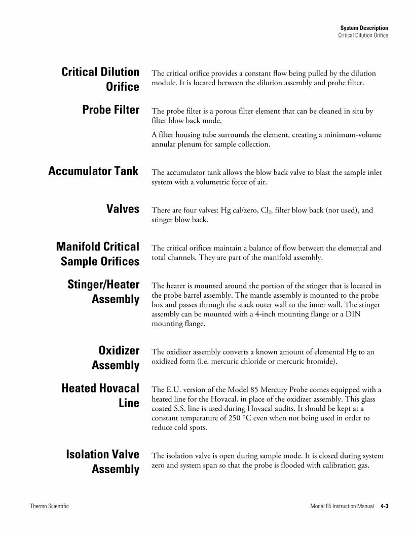
The critical orifice provides a constant flow being pulled by the dilution module. It is located between the dilution assembly and probe filter.
The probe filter is a porous filter element that can be cleaned in situ by filter blow back mode.
A filter housing tube surrounds the element, creating a minimum-volume annular plenum for sample collection.
The accumulator tank allows the blow back valve to blast the sample inlet system with a volumetric force of air.
There are four valves: Hg cal/zero, Cl2, filter blow back (not used), and stinger blow back.
The critical orifices maintain a balance of flow between the elemental and total channels. They are part of the manifold assembly.
The heater is mounted around the portion of the stinger that is located in the probe barrel assembly. The mantle assembly is mounted to the probe box and passes through the stack outer wall to the inner wall. The stinger assembly can be mounted with a 4-inch mounting flange or a DIN mounting flange.
The oxidizer assembly converts a known amount of elemental Hg to an oxidized form (i.e. mercuric chloride or mercuric bromide).
The E.U. version of the Model 85 Mercury Probe comes equipped with a heated line for the Hovacal, in place of the oxidizer assembly. This glass coated S.S. line is used during Hovacal audits. It should be kept at a constant temperature of 250 °C even when not being used in order to reduce cold spots.
The isolation valve is open during sample mode. It is closed during system zero and system span so that the probe is flooded with calibration gas.
Critical Dilution Orifice
Probe Filter
Accumulator Tank
Valves
Manifold Critical Sample Orifices
Stinger/HeaterAssembly
Oxidizer Assembly
Heated HovacalLine
Isolation ValveAssembly

System Description Oxygen Sensor
4-4 Model 85 Instruction Manual Thermo Scientific
For DIN model probes, an oxygen sensor is included for oxygen compensation during sample mode. This is located attached to the probe vent bulkhead.
Oxygen Sensor

Thermo Scientific Model 85 Instruction Manual A-1
Appendix A
Warranty
Seller warrants that the Products will operate or perform substantially in conformance with Seller's published specifications and be free from defects in material and workmanship, when subjected to normal, proper and intended usage by properly trained personnel, for the period of time set forth in the product documentation, published specifications or package inserts. If a period of time is not specified in Seller’s product documentation, published specifications or package inserts, the warranty period shall be one (1) year from the date of shipment to Buyer for equipment and ninety (90) days for all other products (the "Warranty Period"). Seller agrees during the Warranty Period, to repair or replace, at Seller's option, defective Products so as to cause the same to operate in substantial conformance with said published specifications; provided that (a) Buyer shall promptly notify Seller in writing upon the discovery of any defect, which notice shall include the product model and serial number (if applicable) and details of the warranty claim; (b) after Seller’s review, Seller will provide Buyer with service data and/or a Return Material Authorization (“RMA”), which may include biohazard decontamination procedures and other product-specific handling instructions; and (c) then, if applicable, Buyer may return the defective Products to Seller with all costs prepaid by Buyer. Replacement parts may be new or refurbished, at the election of Seller. All replaced parts shall become the property of Seller. Shipment to Buyer of repaired or replacement Products shall be made in accordance with the Delivery provisions of the Seller’s Terms and Conditions of Sale. Consumables, including but not limited to lamps, fuses, batteries, bulbs and other such expendable items, are expressly excluded from the warranty under this warranty.
Notwithstanding the foregoing, Products supplied by Seller that are obtained by Seller from an original manufacturer or third party supplier are not warranted by Seller, but Seller agrees to assign to Buyer any warranty rights in such Product that Seller may have from the original manufacturer or third party supplier, to the extent such assignment is allowed by such original manufacturer or third party supplier.
In no event shall Seller have any obligation to make repairs, replacements or corrections required, in whole or in part, as the result of (i) normal wear and tear, (ii) accident, disaster or event of force majeure, (iii) misuse, fault or negligence of or by Buyer, (iv) use of the Products in a manner for which
Warranty
A-2 Model 85 Instruction Manual Thermo Scientific
they were not designed, (v) causes external to the Products such as, but not limited to, power failure or electrical power surges, (vi) improper storage and handling of the Products or (vii) use of the Products in combination with equipment or software not supplied by Seller. If Seller determines that Products for which Buyer has requested warranty services are not covered by the warranty hereunder, Buyer shall pay or reimburse Seller for all costs of investigating and responding to such request at Seller's then prevailing time and materials rates. If Seller provides repair services or replacement parts that are not covered by the warranty provided in this warranty, Buyer shall pay Seller therefor at Seller's then prevailing time and materials rates. ANY INSTALLATION, MAINTENANCE, REPAIR, SERVICE, RELOCATION OR ALTERATION TO OR OF, OR OTHER TAMPERING WITH, THE PRODUCTS PERFORMED BY ANY PERSON OR ENTITY OTHER THAN SELLER WITHOUT SELLER'S PRIOR WRITTEN APPROVAL, OR ANY USE OF REPLACEMENT PARTS NOT SUPPLIED BY SELLER, SHALL IMMEDIATELY VOID AND CANCEL ALL WARRANTIES WITH RESPECT TO THE AFFECTED PRODUCTS.
THE OBLIGATIONS CREATED BY THIS WARRANTY STATEMENT TO REPAIR OR REPLACE A DEFECTIVE PRODUCT SHALL BE THE SOLE REMEDY OF BUYER IN THE EVENT OF A DEFECTIVE PRODUCT. EXCEPT AS EXPRESSLY PROVIDED IN THIS WARRANTY STATEMENT, SELLER DISCLAIMS ALL OTHER WARRANTIES, WHETHER EXPRESS OR IMPLIED, ORAL OR WRITTEN, WITH RESPECT TO THE PRODUCTS, INCLUDING WITHOUT LIMITATION ALL IMPLIED WARRANTIES OF MERCHANTABILITY OR FITNESS FOR ANY PARTICULAR PURPOSE. SELLER DOES NOT WARRANT THAT THE PRODUCTS ARE ERROR-FREE OR WILL ACCOMPLISH ANY PARTICULAR RESULT.


Find out more at thermofisher.com/mercury
© 2016 Thermo Fisher Scientific Inc. All trademarks are the property of Thermo Fisher Scientific and its subsidiaries unless otherwise specified. EPM_115654-00
USA 27 Forge Parkway Franklin, MA 02038 Ph: (508) 520-0430 Fax: (508) 520-2800 [email protected]
India C/327, TTC Industrial Area MIDC Pawane New Mumbai 400 705, India Ph: +91 22 4157 8800 [email protected]
China +Units 702-715, 7th Floor Tower West, Yonghe Beijing, China 100007 Ph: +86 10 84193588 [email protected]
Europe Ion Path, Road Three, Winsford, Cheshire CW73GA UK Ph: +44 1606 548700 Fax: +44 1606 548711 [email protected]