model-based engineering of an automotive adaptive exterior
TRANSCRIPT

Model-based engineering of an automotive Adaptive Exterior Lighting System
Föcker, Felix; Houdek, Frank; Daun, Marian; Weyer, Thorsten
In: ICB Research Reports - Forschungsberichte des ICB / 2015
This text is provided by DuEPublico, the central repository of the University Duisburg-Essen.
This version of the e-publication may differ from a potential published print or online version.
DOI: https://doi.org/10.17185/duepublico/47024
URN: urn:nbn:de:hbz:464-20180914-091208-1
Link: https://duepublico.uni-duisburg-essen.de/servlets/DocumentServlet?id=47024
License:As long as not stated otherwise within the content, all rights are reserved by the authors / publishers of the work. Usage only with permission, except applicable rules of german copyright law.
Source: ICB-Research Report No. 64, January 2015

�������������������
���������������������������������������������������
Felix Föcker, Frank Houdek, Marian Daun, Thorsten Weyer
Realistic Example Specifications of
Behavioral Requirements and
Functional Design
ICB-Research Report No. 64
January 2015
Research Group Core Research Topics
Prof. Dr. H. H. AdelsbergerInformation Systems for Production and OperationsManagement
E-Learning, Knowledge Management, Skill-Management,Simulation, Artificial Intelligence
Prof. Dr. F. AhlemannInformation Systems and Strategic Management
Strategic planning of IS, Enterprise Architecture Management, IT Vendor Management, Project Portfolio Management, IT Governance, Strategic IT Benchmarking
Prof. Dr. P. ChamoniMIS and Management Science / Operations Research
Information Systems and Operations Research, Business Intelligence, Data Warehousing
Prof. Dr. K. EchtleDependability of Computing Systems
Dependability of Computing Systems
Prof. Dr. S. EickerInformation Systems and Software Engineering
Process Models, Software-Architectures
Prof. Dr. U. FrankInformation Systems and Enterprise Modelling
Enterprise Modelling, Enterprise Application Integration,IT Management, Knowledge Management
Prof. Dr. M. GoedickeSpecification of Software Systems
Distributed Systems, Software Components, CSCW
Prof. Dr. V. GruhnSoftware Engineering
Design of Software Processes, Software Architecture, Usabi-lity, Mobile Applications, Component-based and Generative Software Development
PD Dr. C. KlüverComputer Based Analysis of Social Complexity
Soft Computing, Modeling of Social, Cognitive, and Economic Processes, Development of Algorithms
Prof. Dr. T. KollmannE-Business and E-Entrepreneurship
E-Business and Information Management, E-Entrepreneurship/E-Venture, Virtual Marketplaces and Mobile Commerce, Online-Marketing
Prof. Dr. K. PohlSoftware Systems Engineering
Requirements Engineering, Software Quality Assurance,Software-Architectures, Evaluation of COTS/Open Source-Components
Prof. Dr. Ing. E. RathgebComputer Network Technology
Computer Network Technology
Prof. Dr. R. UnlandData Management Systems and Knowledge Representation
Data Management, Artificial Intelligence, Software Engineering, Internet Based Teaching
Prof. Dr. S. ZelewskiInstitute of Production and Industrial Information Management
Industrial Business Processes, Innovation Management,Information Management, Economic Analyses
ISSN 1860-2770 (Print)ISSN 1866-5101 (Online)
64Model-Based Engineering of an Automotive Adaptive Exterior Lighting System


Die Forschungsberi ch te des Inst ituts für In format ik und Wir tschafts in format ik dienen der Darstel lung vor läufiger Ergebnisse , d ie i . d. R . noch für spätere Veröffen tl ichungen überarbe itet werden . D ie Autoren s ind deshalb für kr it ische Hinwe ise dankbar .
All r ights rese rved . No part of th is report may be reproduced by any means , or translated .
Contact :
Inst itu te for Computer Sc ience and Business In format ion Systems ( ICB) Univers ity of Duisburg-‐‑Essen Univers itätss tr. 9 45141 Essen, Germany
Tel . : 0201-‐‑183-‐‑4041 Fax : 0201-‐‑183-‐‑4011 Email : i cb@uni-‐‑duisburg -‐‑essen.de
Authors ’ Address :
Fel ix Föcker Univers ity of Duisburg-‐‑Essen Univers itätss tr. 2 , 45127 Essen, Germany
fel ix. foecker@uni-‐‑due.de
Frank Houdek Daimler AG Post fach 2360, 89013 Ulm, Germany
frank.houdek@daimle r.com
Marian Daun , Thorsten Weyer paluno, Univers ity of Duisburg -‐‑Essen Ger lingstr. 16 , 45127 Essen, Germany
mar [email protected] -‐‑due.de
thorsten [email protected] i-‐‑due.de
The ICB Research Reports comprise preliminary resul ts which wi l l usually be revised for subsequent publicat ions . Cr it ica l comments would be appreciated by the authors .
A lle Rechte vorbehalten. Insbesondere d ie der Überse tzung, des Nachdruckes, des Vortrags, der Entnahme von Abbildungen und Tabell en – auch bei nur auszugswe iser Verwertung .
ISSN 1860-‐‑2770 (Pr int) ISSN 1866-‐‑5101 (Online)
ICB Research Reports
Edited by:
Prof . Dr . Heimo Adelsberger Prof . Dr . F reder ik Ahlemann Prof . Dr . K laus Echt le Prof . Dr . Stefan E icker Prof . Dr . Ulr ich Frank Prof . Dr . Michael Goedicke Prof . Dr . Volker Gruhn PD Dr. Chri st ina K lüver Prof . Dr . Tobias Kollmann Prof . Dr . K laus Pohl Prof . Dr . Erwin P. Rathgeb Prof . Dr . Rainer Unland Prof . Dr . Stephan Zelewski


i
Abstract Model-‐‑based engineering is a well-‐‑established approach to cope with the complexity of today’s embedded systems. Furthermore, model-‐‑based engineering can address industry needs for highly automated development solutions to foster correctness of safety-‐‑critical systems. In contrast, there is a vital lack of accessible specification documents for researchers for evaluation purposes. Evaluation of proposed engineering methods often relies on academic examples, automatically created unrealistic artificial models, or simple industrial specification excerpts. This research report aims at supporting researchers with model-‐‑based specifications of a real-‐‑world system on a competitive level of complexity. Therefore, a model-‐‑based specification of an Adaptive Exterior Lighting System (ELS) is presented that is part of an Automotive System Cluster (ASC). An ELS provides fundamental and additional functionalities for the well-‐‑known turn signal and low / high beam headlights. The specification documents the behavioral requirements and the functional design of the ELS, which are important artifacts in function-‐‑centered engineering. As modeling languages ITU Message Sequence Charts, Function Network, and Function Behavior Diagrams are used.

ii

i i i
Table of Content 1 INTRODUCTION ...................................................................................................................................... 1
1.1 MOTIVATION ............................................................................................................................................. 1
1.2 THE AUTOMOTIVE SYSTEM CLUSTER ....................................................................................................... 1
1.3 FUNCTION-‐‑CENTERED ENGINEERING ...................................................................................................... 2
1.3.1 Behavioral Requirements .................................................................................................................. 2
1.3.2 Functional Design ............................................................................................................................ 3
2 SPECIFICATION OF THE BEHAVIORAL REQUIREMENTS ......................................................... 4
2.1 STRUCTURE OF THE BEHAVIORAL REQUIREMENTS .................................................................................. 5
2.2 CHANGE SETTINGS .................................................................................................................................... 5
2.2.1 Set Rotary Light Switch ................................................................................................................... 6
2.2.2 Set Pitman Arm ............................................................................................................................... 7
2.2.3 Set Hazard Warning Light Switch ................................................................................................ 12
2.2.4 Set Instrument Cluster .................................................................................................................. 13
2.2.5 Set Darkness Switch ....................................................................................................................... 14
2.2.6 Set Ignition Key .............................................................................................................................. 15
2.3 CONTROL HEADLIGHTS .......................................................................................................................... 16
2.3.1 Control High Beam Headlights ...................................................................................................... 17
2.3.2 Control Low Beam Headlights ....................................................................................................... 23
2.3.3 Handle Overvoltage ....................................................................................................................... 33
2.4 CONTROL TURN SIGNAL ......................................................................................................................... 34
2.4.1 Direction Blinking Left .................................................................................................................. 35
2.4.2 Direction Blinking Right ............................................................................................................... 38
2.4.3 Hazard Warning Light ................................................................................................................... 39
2.5 DETECT FAULTS ....................................................................................................................................... 41
3 SPECIFICATION OF THE FUNCTIONAL DESIGN ........................................................................ 42
3.1 STRUCTURE OF THE FUNCTIONAL DESIGN ............................................................................................. 45
3.2 CONTROL HEADLIGHTS .......................................................................................................................... 47
3.2.1 Control High Beam Headlights ...................................................................................................... 48
3.2.2 Control Low Beam Headlights ....................................................................................................... 52
3.2.3 Handle Overvoltage ....................................................................................................................... 63
3.3 CONTROL TURN SIGNAL ......................................................................................................................... 63
3.3.1 Direction Blinking Left .................................................................................................................. 65

iv
3.3.2 Direction Blinking Right ............................................................................................................... 67
3.3.3 Hazard Warning Light ................................................................................................................... 68
3.4 DEFECT FAULTS ....................................................................................................................................... 69
4 REFERENCES ............................................................................................................................................ 70

v
Table of Figures FIGURE 1: HMSC -‐‑ ADAPTIVE EXTERIOR LIGHTING SYSTEM ................................................................................. 5
FIGURE 2: HMSC -‐‑ CHANGE SETTINGS .................................................................................................................... 6
FIGURE 3: HMSC -‐‑ SET ROTARY LIGHT SWITCH ..................................................................................................... 6
FIGURE 4: MSC -‐‑ SWITCH TO AUTO ........................................................................................................................ 7
FIGURE 5: MSC -‐‑ SWITCH TO EXTERIOR LIGHT ON ................................................................................................. 7
FIGURE 6: MSC -‐‑ SWITCH TO OFF ............................................................................................................................ 7
FIGURE 7: HMSC -‐‑ SET PITMAN ARM ..................................................................................................................... 8
FIGURE 8: MSC -‐‑ ACTIVATE HIGH BEAM ................................................................................................................. 9
FIGURE 9: MSC -‐‑ DEACTIVATE HIGH BEAM ............................................................................................................ 9
FIGURE 10: MSC -‐‑ ACTIVATE DIRECTION INDICATOR .......................................................................................... 10
FIGURE 11: MSC -‐‑ ACTIVATE PERMANANTLY ....................................................................................................... 10
FIGURE 12: MSC -‐‑ DEACTIVATE DIRECTION INDICATOR ...................................................................................... 11
FIGURE 13: MSC -‐‑ SET HAZARD WARNING LIGHT SWITCH .................................................................................. 12
FIGURE 14: HMSC -‐‑ SET INSTRUMENT CLUSTER .................................................................................................. 13
FIGURE 15: MSC -‐‑ SET DAYTIME TUNNING LIGHT ............................................................................................... 13
FIGURE 16: MSC -‐‑ SET AMBIENT LIGHT ................................................................................................................ 13
FIGURE 17: MSC -‐‑ SET DARKNESS SWITCH ........................................................................................................... 14
FIGURE 18: HMSC -‐‑ SET IGNITION KEY ................................................................................................................. 15
FIGURE 19: MSC -‐‑ INSERT IGNITION KEY .............................................................................................................. 15
FIGURE 20: MSC -‐‑ REMOVE IGNITION KEY ........................................................................................................... 15
FIGURE 21: MSC -‐‑ START ENGINE ......................................................................................................................... 16
FIGURE 22: MSC -‐‑ STOP ENGINE ........................................................................................................................... 16
FIGURE 23: HMSC -‐‑ CONTROL HEADLIGHTS ........................................................................................................ 16
FIGURE 24: HMSC -‐‑ CONTROL HIGH BEAM HEADLIGHTS .................................................................................... 17
FIGURE 25: MSC -‐‑ ACTIVATE MANUAL HIGH BEAM HEADLIGHTS ....................................................................... 18
FIGURE 26: MSC -‐‑ ACTIVATE ADAPTIVE HIGH BEAM HEADLIGHTS ..................................................................... 19
FIGURE 27: MSC -‐‑ DEACTIVATE HIGH BEAM HEADLIGHTS .................................................................................. 20
FIGURE 28: MSC -‐‑ CHECK VOLTAGE ...................................................................................................................... 21
FIGURE 29: MSC -‐‑ ADAPT HIGH BEAM HEADLIGHTS ........................................................................................... 22
FIGURE 30: HMSC -‐‑ CONTROL LOW BEAM HEADLIGHTS ..................................................................................... 23
FIGURE 31: HMSC -‐‑ ACTIVATE LOW BEAM HEADLIGHTS ..................................................................................... 23
FIGURE 32: MSC -‐‑ ACTIVATE AMBIENT LIGHT ...................................................................................................... 24

vi
FIGURE 33: MSC -‐‑ ACTIVATE DAYTIME RUNNING LIGHT ..................................................................................... 25
FIGURE 34: MSC -‐‑ ACTIVATE LOW BEAM HEADLIGHTS MANUAL ........................................................................ 25
FIGURE 35: MSC -‐‑ ACTIVATE LOW BEAM HEADLIGHTS AUTOMATIC ................................................................... 26
FIGURE 36: HMSC -‐‑ DEACTIVATE LOW BEAM HEADLIGHTS ................................................................................. 27
FIGURE 37: MSC -‐‑ DEACTIVATE AMBIENT LIGHT ................................................................................................. 28
FIGURE 38: MSC -‐‑ DEACTIVATE DAYTIME RUNNING LIGHT ................................................................................ 29
FIGURE 39: MSC -‐‑ DEACTIVATE LOW BEAM HEADLIGHTS AUTOMATIC .............................................................. 30
FIGURE 40: MSC -‐‑ DEACTIVATE LOW BEAM HEADLIGHTS MANUAL ................................................................... 31
FIGURE 41: MSC -‐‑ CHECK CONDITIONS AND SWITCH OFF ................................................................................... 31
FIGURE 42: MSC -‐‑ CONTROL CORNERING LIGHT ................................................................................................ 32
FIGURE 43: MSC -‐‑ HANDLE OVERVOLTAGE .......................................................................................................... 33
FIGURE 44: HMSC -‐‑ CONTROL TURNING LIGHTS .................................................................................................. 34
FIGURE 45: MSC -‐‑ ACTIVATE DIRECTION BLINKING LEFT .................................................................................... 35
FIGURE 46: MSC -‐‑ ACTIVATE TIP BLINKING LEFT ................................................................................................. 36
FIGURE 47: MSC -‐‑ DEACITVATE DIRECTION BLINKING LEFT ................................................................................ 37
FIGURE 48: MSC -‐‑ ACTIVATE DIRECTION BLINKING RIGHT .................................................................................. 38
FIGURE 49: MSC -‐‑ DEACTIVATE DIRECTION BLINKING RIGHT ............................................................................. 38
FIGURE 50: MSC -‐‑ ACTIVATE TIP BLINKING RIGHT ............................................................................................... 39
FIGURE 51: MSC -‐‑ CONTROL HAZARD WARNING LIGHT ...................................................................................... 40
FIGURE 52: MSC -‐‑ DETECT FAULTS ....................................................................................................................... 41
FIGURE 53: CONTEXT DIAGRAM ........................................................................................................................... 45
FIGURE 54: FUNCTION NETWORK DIAGRAM – CONTROL ADAPTIVE EXTERIOR LIGHTING SYSTEM .................. 46
FIGURE 55: FUNCTION NETWORK DIAGRAM -‐‑ CONTROL HEADLIGHTS .............................................................. 47
FIGURE 56: FUNCTION NETWORK DIAGRAM -‐‑ CONTROL HIGH BEAM HEADLIGHTS .......................................... 48
FIGURE 57: INTERFACE AUTOMATON -‐‑ ACTIVATE MANUAL HIGH BEAM HEADLIGHTS ..................................... 49
FIGURE 58: INTERFACE AUTOMATON -‐‑ ACTIVATE ADAPTIVE HIGH BEAM HEADLIGHTS .................................... 49
FIGURE 59: INTERFACE AUTOMATON -‐‑ DEACTIVATE HIGH BEAM HEADLIGHTS ................................................. 50
FIGURE 60: INTERFACE AUTOMATON -‐‑ CHECK VOLTAGE .................................................................................... 50
FIGURE 61: INTERFACE AUTOMATON -‐‑ ADAPT HIGH BEAM HEADLIGHTS .......................................................... 51
FIGURE 62: FUNCTION NETWORK DIAGRAM -‐‑ CONTROL LOW BEAM HEADLIGHTS ........................................... 52
FIGURE 63: FUNCTION NETWORK DIAGRAM -‐‑ ACTIVATE LOW BEAM HEADLIGHTS ........................................... 53
FIGURE 64: INTERFACE AUTOMATON -‐‑ ACTIVATE LOW BEAM HEADLIGHTS MANUAL ...................................... 54
FIGURE 65: INTERFACE AUTOMATON -‐‑ ACTIVATE LOW BEAM HEADLIGHTS AUTOMATIC ................................. 54

vi i
FIGURE 66: INTERFACE AUTOMATON -‐‑ ACTIVATE DAYTIME RUNNING LIGHT ................................................... 55
FIGURE 67: FUNCTION NETWORK DIAGRAM -‐‑ ACTIVATE AMBIENT LIGHT ......................................................... 56
FIGURE 68: INTERFACE AUTOMATON -‐‑ CHECK CONDITIONS ............................................................................... 57
FIGURE 69: INTERFACE AUTOMATON -‐‑ ACTIVATE BY KEY ................................................................................... 57
FIGURE 70: INTERFACE AUTOMATON -‐‑ ACTIVATE BY DOOR ................................................................................ 57
FIGURE 71: FUNCTION NETWORK DIAGRAM -‐‑ DEACTIVATE LOW BEAM HEADLIGHTS ...................................... 58
FIGURE 72: INTERFACE AUTOMATON -‐‑ DEACTIVATE LOW BEAM HEADLIGHTS MANUAL .................................. 59
FIGURE 73: INTERFACE AUTOMATON -‐‑ DEACTIVATE LOW BEAM HEADLIGHTS AUTOMATIC ............................. 59
FIGURE 74: INTERFACE AUTOMATON -‐‑ DEACTIVATE DAYTIME RUNNING LIGHT ............................................... 59
FIGURE 75: INTERFACE AUTOMATON -‐‑ DEACTIVATE AMBIENT LIGHT ................................................................ 60
FIGURE 76: INTERFACE AUTOMATON -‐‑ CHECK CONDITIONS AND SWITCH OFF ................................................. 60
FIGURE 77: FUNCTION NETWORK DIAGRAM -‐‑ CONTROL CORNERING LIGHT ..................................................... 61
FIGURE 78: INTERFACE AUTOMATON -‐‑ CHECK CONDITIONS ............................................................................... 62
FIGURE 79: INTERFACE AUTOMATON -‐‑ ACTIVATE LEFT CORNERING LIGHT ....................................................... 62
FIGURE 80: INTERFACE AUTOMATON -‐‑ DEACTIVATE LEFT CORNERING LIGHT ................................................... 62
FIGURE 81: INTERFACE AUTOMATON -‐‑ ACTIVATE RIGHT CORNERING LIGHT ..................................................... 63
FIGURE 82: INTERFACE AUTOMATON -‐‑ DEACTIVATE RIGHT CORNERING LIGHT ................................................ 63
FIGURE 83: INTERFACE AUTOMATON -‐‑ HANDLE OVERVOLTAGE ......................................................................... 63
FIGURE 84: FUNCTION NETWORK DIAGRAM -‐‑ CONTROL TURN LIGHTS (MESSAGES) ........................................ 64
FIGURE 85: FUNCTION NETWORK DIAGRAM -‐‑ CONTROL TURN LIGHTS (DEPENDENCIES) ................................. 65
FIGURE 86: INTERFACE AUTOMATON -‐‑ ACTIVATE DIRECTION BLINKING LEFT ................................................... 66
FIGURE 87: INTERFACE AUTOMATON -‐‑ DEACTIVATE DIRECTION BLINKING LEFT .............................................. 66
FIGURE 88: INTERFACE AUTOMATON -‐‑ ACTIVATE TIP BLINKING LEFT ................................................................ 66
FIGURE 89: INTERFACE AUTOMATON -‐‑ ACTIVATE DIRECTION BLINKING RIGHT ................................................ 67
FIGURE 90: INTERFACE AUTOMATON -‐‑ ACTIVATE TIP BLINKING RIGHT ............................................................. 67
FIGURE 91: INTERFACE AUTOMATON -‐‑ DEACTIVATE DIRECTION BLINKING RIGHT ............................................ 67
FIGURE 92: INTERFACE AUTOMATON -‐‑ ACTIVATE HAZARD WARNING LIGHT .................................................... 68
FIGURE 93: INTERFACE AUTOMATON -‐‑ DEACTIVATE HAZARD WARNING LIGHT ............................................... 69
FIGURE 94: INTERFACE AUTOMATON -‐‑ DETECT FAULTS ..................................................................................... 69


Model-‐‑Based Engineering of an Automotive Adaptive Exterior Lighting System
1
1 Introduction
This research report presents model-‐‑based specifications of an Adaptive Exterior Lighting System (ELS), which is part of an Automotive System Cluster (ASC). The specifications document the behavioral requirements and the functional design of the ELS, which are important artifacts in function-‐‑centered engineering. As modeling languages, ITU Message Sequence Charts (cf. (ITU 2011)) and Function Network and Function Behavior Diagrams (cf. (Daun et al 2014)) are used.
1.1 Motivation
Model-‐‑based engineering is a well-‐‑established approach to cope with the complexity of today’s embedded systems (cf. (Beetz and Böhm 2012)). Furthermore, model-‐‑based engineering can address industry needs for highly automated development solutions to foster correctness of safety-‐‑critical systems (cf. (Sikora et al 2012)). In contrast, there is a vital lack of accessible specification documents for researchers for evaluation purposes. Evaluation of proposed engineering methods often relies on academic examples, automatically created unrealistic artificial models, or simple industrial specification excerpts. This research report aims at supporting researchers with model-‐‑based specifications of a real-‐‑world system on a competitive level of complexity.
The specifications were developed as part of the SPES evaluation strategy during the joint research project SPES 2020 XTCore. The behavioral requirements specification (Section 2) is a result of the application of SPES specification techniques for the model-‐‑based documentation of requirements (cf. (Daun et al 2012)). The specification of the functional design (Section 3) results from the application of techniques described in (Daun et al 2014). In conclusion, the specifications document the applicability of the proposed approaches. Hence, the given specifications are the basis for further research and evaluation activities regarding the application of validation, verification, and model transformation approaches, which make use of behavioral requirements and functional design.
1.2 The Automotive System Cluster
The ASC can be considered as a comfort control system that consists of two subsystems, namely the ELS and an Adaptive Cruise Control System (ACC). While this research report provides insights into the model-‐‑based specification of the ELS, a natural language description of the ASC’s system requirements specification can be found in (Houdek 2013).
An ELS provides fundamental and additional functionalities for the well-‐‑known turn signal and low / high beam headlights. For example, the control of the driving direction indicators of the vehicle in dependence of the pitman arm, the control of the low beam headlights in

Introduction
2
dependence of the light rotary switch and the daytime running light settings, and the control of the high beam headlights in dependence of the high beam switch and the detection of advancing vehicles.
1.3 Function-‐‑Centered Engineering
In the development of embedded systems, function-‐‑centered engineering is a commonly used approach to cope with the emerging number and complexity of systems’ software functions and their interdependencies (cf. (Pretschner et al 2007)). Function-‐‑centered engineering focuses on the functional design as the central development artifact throughout the whole engineering process.
As described in (Brinkkemper and Pachidi 2010) and (Jantsch and Sander 2000), the functional design specifies the functions to be implemented, their hierarchical structure, and the planned behavior of each function. In addition, it specifies interactions and dependencies between the functions in such a way that the interplay between different functions fulfills the behavioral properties documented in the behavioral requirements (e.g., to optimize the function deployment and thereby to minimize the number of expensive electronic control units, to avoid redundancies affecting the maintainability of the system, or to foster re-‐‑use of implemented functions). The initial version of the functional design is based on the behavioral requirements that are in turn reflecting the consolidated stakeholder intentions with respect to the system to be built.
Next, the behavioral requirements and the functional design are briefly characterized as outlined in (Daun et al 2014).
1.3.1 Behavioral Requirements
In general, behavioral requirements models can be differentiated into state-‐‑based and interaction-‐‑based models. During requirements engineering, especially interaction-‐‑based models are widely used, for example, to document scenarios and to specify the essential interfaces.
In the engineering of embedded software, message sequence charts (MSCs) are commonly used for the specification of interaction-‐‑based behavioral requirements models (cf. (Weber and Weisbrod 2002)). The Z.120 standard (ITU 2011) distinguishes between basic message sequence charts (bMSCs) and high-‐‑level message sequence charts (hMSCs). bMSCs define specific situations detailing the behavior in terms of messages exchanged between the system and entities in the environment. hMSCs structure the bMSCs according to their execution order and create a complete system specification.

Model-‐‑Based Engineering of an Automotive Adaptive Exterior Lighting System
3
1.3.2 Functional Design
The functional design consists of specifications of the system functions to be implemented and their hierarchical structure. Additionally, the intended behavior of each system function is specified as well as the interactions and dependencies between system functions.
Different diagram types are used to document the functional design. Function network diagrams document the functional dependencies between system functions that are embedded in given context functions. Context functions are functions that can be used by the system to be built but are not a subject of the development process. Afterwards, each function is detailed by a function behavior diagram that specifies the behavior of the function in terms of an interface automaton (cf. (de Alfaro and Henzinger 2001)).

Specification of the Behavioral Requirements
4
2 Specification of the Behavioral Requirements
The model-‐‑based specification of behavioral requirements -‐‑ as described in the following -‐‑ comprises the combinations of MSCs of the ELS in hMSCs and more detailed interactions in bMSCs. The Structure (highest abstraction-‐‑level) of the behavioral requirements is described in Section 2.1. Breaking down the hMSCs to bMSCs results in up to five abstraction-‐‑levels. The sections 2.2, 2.3, 2.4, and 2.5 represent the second abstraction-‐‑level and the main functions of the ELS as outlined above.
The specified instances of the ELS are subdivided into system-‐‑ and context-‐‑instances. An overview is given in Table 1. For an improved identification, the instances are represented by different fillings of the shapes.
Table 1: MSC Instances
Instance Shape
Body Controller
ContextInstance
Camera Unit
Darkness Switch
Door Control Unit
Driver
ESP Control Unit
Hazard Warning Light Switch
High Beam Module
Ignition Key
Pitman Arm
Roof Console Control Unit
Rotary Light Switch
Adaptive High Beam Headlight SystemInstance
Defect Detection
Instrument Cluster
Low Beam Headlight
Turning Light

Model-‐‑Based Engineering of an Automotive Adaptive Exterior Lighting System
5
2.1 Structure of the Behavioral Requirements
The behavioral requirements are structured into four referenced MSCs that are applicable in a loop (see Figure 1). These referenced MSCs represent the main functionalities of the ELS to change the global settings of the system by a user, to control the headlights and the turn signal, and to detect faults.
Change Settings
Control Turn Signal
Control Headlights
1 – hMSC – Adaptive Exterior Lighting System
Detect Faults
Figure 1: hMSC -‐‑ Adaptive Exterior Lighting System
2.2 Change Settings
In Figure 1, all required settings of the system are condensed and refer to the appropriate MSC. It is either possible to set the rotary light switch (see Section 2.2.1), the pitman arm (see Section 2.2.2), the hazard warning light switch (see Section 2.2.3), the instrument cluster (see Section 2.2.4), the darkness switch (see Section 2.2.5), or the ignition key (see Section 2.2.6).

Specification of the Behavioral Requirements
6
Set Rotary Light Switch
Set Pitman Arm
Set Hazard Warning Light Switch
Set Darkness Switch
Set Instrument Cluster
Set Ignition Key
1.1 – hMSC – Change Settings
Figure 2: hMSC -‐‑ Change Settings
2.2.1 Set Rotary Light Switch
The Rotary Light Switch is a part of the user interface and has three positions (left -‐‑ “Off”, middle -‐‑ “Auto” and right -‐‑ “Exterior Light On”), which represent the modes of the low beam headlight. In Figure 3, the possible combinations to switch these modes are presented. The position “Off” and “Exterior Light On” can only be reached from position “Auto”, and “Auto” can only be reached from “Off” and “Exterior Light On”.
Switch to Off
whenOff
whenAuto
whenExterior Light On
Switch to Exterior Light On
Switch to Auto
1.1.1 – hMSC – Set Rotary Light Switch
Figure 3: hMSC -‐‑ Set Rotary Light Switch
If the Driver wants to switch the position and the conditions are fulfilled, he adjusts the switch and the Rotary Light Switch changes its mode and the conditions (see Figure 4, Figure 5, and Figure 6).

Model-‐‑Based Engineering of an Automotive Adaptive Exterior Lighting System
7
Driver Rotary Light Switch
Adjust Switch
Switch to Auto Position
Auto
1.1.1.1 – MSC – Switch to Auto
Figure 4: MSC -‐‑ Switch to Auto
Driver Rotary Light Switch
Adjust Switch
Switch to Exterior Light On Position
Exterior Light On
1.1.1.2 – MSC – Switch to Exterior Light On
Figure 5: MSC -‐‑ Switch to Exterior Light On
Driver Rotary Light Switch
Adjust Switch
Switch to Off Position
Off
1.1.1.3 – MSC – Switch to Off
Figure 6: MSC -‐‑ Switch to Off
2.2.2 Set Pitman Arm
The Pitman Arm is a control lever attached to the steering column and part of the user interface. By switching its position, the Pitman Arm provides the functionalities to activate or deactivate the high beam and the direction indicators (see Figure 7). Basically, it is possible to adjust the Pitman Arm on the horizontal and the vertical axis. When the Pitman Arm is in the horizontal neutral position the high beam can be activated and when the Pitman Arm is in a vertical neutral position the direction indicator can be activated. Subsequently, an activated direction indicator can be activated permanently by engaging the vertical position of the Pitman Arm. In the following, the referenced bMSCs are described and provide detailed information about the positions of the Pitman Arm.

Specification of the Behavioral Requirements
8
Activate High Beam
Activate Direction Indicator
whenHorizontal Neutral
Deactivate High Beam
whenVertical Neutral
Deactivate Direction Indicator
Activate Permanantly
1.1.2 – hMSC – Set Pitman Arm
Figure 7: hMSC -‐‑ Set Pitman Arm

Model-‐‑Based Engineering of an Automotive Adaptive Exterior Lighting System
9
High Beam Headlights. If the Driver wants to activate the high beam headlights, he can either push away and engage or pull and hold the Pitman Arm (see Figure 8). By pushing away and engaging the Pitman Arm, the high beam headlights and the adaptive high beam are activated permanently. To activate the high beam headlights temporary (so called flasher), the Driver needs to pull and hold the Pitman Arm. To deactivate the high beam headlights, the Driver either needs to release the Pitman Arm from the pulled position or disengage it from the pushed position (see Figure 9).
Driver Pitman Arm
Push Away From Driverand Engage
Pushed
Switch to Pushed Position
Pull Towards Driver and Hold to Flash
Pulled
Switch to Pulled Position
alt
High Beam HeadlightsActivated
High Beam HeadlightsActivated
1.1.2.1 – MSC – Activate High Beam
Figure 8: MSC -‐‑ Activate High Beam
Driver Pitman Arm
Release from Pulled Position
Horizontal Neutral
Switch back to Horizontal Neutral Position
altwhenPulled,
High Beam HeadlightsActivated
Disengage from Pushed Position
Horizontal Neutral
Switch back to Horizontal Neutral Position
High Beam HeadlightsDeactivated
whenPulled,
High Beam HeadlightsActivated
High Beam HeadlightsDeactivated
1.1.2.2 – MSC – Deactivate High Beam
Figure 9: MSC -‐‑ Deactivate High Beam

Specification of the Behavioral Requirements
10
Direction Indicator. The Driver can either activate the left or right direction indicators by moving the Pitman Arm down or up (see Figure 10). The distinction between temporary and permanent activation of the direction indicators is made by the Pitman Arm deflection. If the Pitman Arm is engaged by the Driver, the direction indicators are activated permanently, otherwise temporarily (see Figure 11).
Driver Pitman Arm
Move Up to Blink Right
Up
Switch to Upper Position
Move Down to Blink Left
Down
Switch to Lower Position
alt
1.1.2.3 – MSC – Activate Direction Indicator
Figure 10: MSC -‐‑ Activate Direction Indicator
Driver Pitman Arm
Engage to Upper Position
Engaged Up
Engage to Upper Position
Engage to Lower Position
Engaged Down
Engage to Lower Position
whenDown
whenUp
alt
1.1.2.4 – MSC – Activate Permanently
Figure 11: MSC -‐‑ Activate Permanently

Model-‐‑Based Engineering of an Automotive Adaptive Exterior Lighting System
11
To deactivate the direction indicators, the Driver needs to disengage or release the Pitman Arm from the upper or lower position (see Figure 12).
Driver Pitman Arm
Release from Upper Position
alt
Disengage from Upper Position
whenEngaged Up
whenUp
Vertical Neutral
Switch back to Vertical Neutral Position
Vertical Neutral
Switch back to Vertical Neutral Position
Release from lower Position
whenDown
Vertical Neutral
Switch back to Vertical Neutral Position
Disengage from lower Position
whenEngaged Down
Vertical Neutral
Switch back to Vertical Neutral Position
1.1.2.5 – MSC – Deactivate Direction Indicator
Figure 12: MSC -‐‑ Deactivate Direction Indicator

Specification of the Behavioral Requirements
12
2.2.3 Set Hazard Warning Light Switch
The Hazard Warning Light Switch is also part of the user interface and can either be switched “On” or “Off” (see Figure 13). When the Driver switches the Hazard Warning Light Switch on, the hazard warning light gets activated -‐‑ otherwise deactivated.
Driver Hazard Warning Light Switch
Switch Hazard Warning Light On
altwhen
Hazard Warning LightDeactivated
Hazard Warning LightActivated
Switch Hazard Warning Light Off
whenHazard Warning Light
Activated
Hazard Warning LightDeactivated
Activate Hazard Warning Light
Deactivate Hazard Warning Light
1.1.3 – MSC – Set Hazard Warning Light Switch
Figure 13: MSC -‐‑ Set Hazard Warning Light Switch

Model-‐‑Based Engineering of an Automotive Adaptive Exterior Lighting System
13
2.2.4 Set Instrument Cluster
The Instrument Cluster provides access to additional settings for the low beam headlights. Either the settings for the daytime running light or the settings for the ambient light could be accessed (see Figure 14).
Set Daytime Running Light
SetAmbient Light
1.1.4 – hMSC – Set Instrument Cluster
Figure 14: hMSC -‐‑ Set Instrument Cluster
The Daytime Running Light can be activated or deactivated by the Driver in the Instrument Cluster in the menu “Settings, Vehicle settings, Daytime running light” (see Figure 15). Furthermore, the Ambient Light can be activated or deactivated in the menu “Settings, Vehicle settings, Ambient lighting” (see Figure 16).
Driver Instrument Cluster
Switch Daytime Running Light On
altwhen
Daytime Running LightDeactivated
Daytime Running LightActivated
Switch Daytime Running Light Off
whenDaytime Running Light
Activated
Daytime Running LightDeactivated
Activate Daytime Running Light
Deactivate Daytime Running Light
1.1.4.1 – MSC – Set Daytime Running Light
Figure 15: MSC -‐‑ Set Daytime Running Light
Driver Instrument Cluster
Switch Ambient Light On
altwhen
Ambient LightDeactivated
Ambient LightActivated
Switch Ambient Light Off
whenAmbient Light
Activated
Ambient LightDeactivated
Activate Ambient Light
Deactivate Ambient Light
1.1.4.2 – MSC – Set Ambient Light
Figure 16: MSC -‐‑ Set Ambient Light

Specification of the Behavioral Requirements
14
2.2.5 Set Darkness Switch
The Darkness Switch is part of the user interface and mounted in the area of the upper control field -‐‑ but only available in armored vehicles. If the Darkness Switch is available, the Driver can activate or deactivate the Darkness Mode (see Figure 17).
Driver Darkness Switch
Switch Darkness Mode On
altwhen
Darkness ModeDeactivated
Darkness ModeActivated
Switch Darkness Mode Off
whenDarkness Mode
Activated
Darkness ModeDeactivated
Activate Darkness Mode
Deactivate Darkness Mode
1.1.5 – MSC – Set Darkness Switch
Figure 17: MSC -‐‑ Set Darkness Switch

Model-‐‑Based Engineering of an Automotive Adaptive Exterior Lighting System
15
2.2.6 Set Ignition Key
A simplified model of the Ignition Key is presented in Figure 18 to ensure a consistent behavior of the ELS. First of all, the key could be inserted. When the key is inserted, the engine could be started or stopped. As long as the engine is stopped, it is possible to remove the key.
whenInserted
InsertIgnition Key
whenEngine Started
Stop Engine
Start EngineRemoveIgnition Key
Simplified modelof the ignition key.
whenEngine
Stopped
1.1.6 – hMSC – Set Ignition Key
Figure 18: hMSC -‐‑ Set Ignition Key
All referenced MSCs in Figure 18 need to be initialized by the Driver and lead to a change of the local conditions of the Ignition Key (see Figure 19, Figure 20, Figure 21, and Figure 22).
Driver Ignition Key
whenRemoved
Insert Ignition Key
Inserted
1.1.6.1 – MSC – Insert Ignition Key
Figure 19: MSC -‐‑ Insert Ignition Key
Driver Ignition Key
Remove Ignition Key
Removed
1.1.6.2 – MSC – Remove Ignition Key
Figure 20: MSC -‐‑ Remove Ignition Key

Specification of the Behavioral Requirements
16
Driver Ignition Key
Start Engine
Engine Started
1.1.6.3 – MSC – Start Engine
Figure 21: MSC -‐‑ Start Engine
Driver Ignition Key
Stop Engine
Engine Stopped
1.1.6.4 – MSC – Stop Engine
Figure 22: MSC -‐‑ Stop Engine
2.3 Control Headlights
The control of the headlights (see Figure 23) comprises the control of the high beam headlights (see Section 2.3.1), the control of the low beam headlights (see Section 2.3.2) and the handling of overvoltage (see Section 2.3.3).
Control High Beam
Headlights
Handle Overvoltage
Control Low Beam
Headlights
1.2 – hMSC – Control Headlights
Figure 23: hMSC -‐‑ Control Headlights

Model-‐‑Based Engineering of an Automotive Adaptive Exterior Lighting System
17
2.3.1 Control High Beam Headlights
The behavioral requirements for the control of the high beam headlights are structured in Figure 24. Either the high beam headlights are activated or deactivated. When the high beam headlights are deactivated, the manual or adaptive high beam headlights could be activated (see Section 2.3.1.1). Subsequently either the voltage is checked and the high beam headlight gets adapted (see Section 2.3.1.3) or the high beam headlights could be deactivated (see Section 2.3.1.2) if they were activated.
Activate Adaptive High Beam Headlights
Activate Manual High Beam Headlights
Deactivate High Beam Headlights
Adapt High Beam Headlights
whenDeactivated
whenActivated
Check Voltage
1.2.1 – hMSC – Control High Beam Headlights
Figure 24: hMSC -‐‑ Control High Beam Headlights

Specification of the Behavioral Requirements
18
2.3.1.1 Activate High Beam Headlights
When the high beam headlights are activated by the Pitman Arm and the Rotary Light Switch is in “Off”-‐‑ or “Exterior Light On”-‐‑Position the Adaptive High Beam Headlight switches to activated and activates the high beam headlights with a fixed illumination area of 220m due to the High Beam Module (see Figure 25). The activation via the Pitman Arm includes the so-‐‑called flasher (see Section 2.2.2).
Pitman ArmHigh Beam
ModuleAdaptive High
Beam Headlight
whenHigh Beam Headlights
Activated
High Beam Headlights Active
Activate
Activated
Activate HighBeam Headlights
Rotary Light Switch
whenOff
whenExterior Light On
alt
Not in Auto Mode
Illumination Areas = 220m
1.2.1.2 – MSC – Activate Manual High Beam Headlights
Figure 25: MSC -‐‑ Activate Manual High Beam Headlights

Model-‐‑Based Engineering of an Automotive Adaptive Exterior Lighting System
19
The activation of the adaptive high beam headlight is initialized by the pushed position of the Pitman Arm and the auto mode of the Rotary Light Switch (see Figure 26). After activating the high beam headlights at the High Beam Module, the voltage needs to be checked. The adaption of the high beam headlights is not available with subvoltage and the illumination area is set to default. Otherwise, the adaption is activated and the operational availability of is indicated by a symbol in the Instrument Cluster.
Pitman ArmHigh Beam
ModuleAdaptive High
Beam Headlight
whenHigh Beam
Headlights Activated,Pushed
High Beam Headlights Active
Activate
Activated
Rotary Light Switch
whenAuto
Auto Mode
Illumination Areas = 220m
alt
InstrumentCluster
Check Voltage
whenSubvoltage
whenNormal Voltage
BodyController
Voltage
ActivateAdaption
AdaptionActivated
Operational Availability
Activate HighBeam Headlights
1.2.1.3 – MSC – Activate Adaptive High Beam Headlights
Figure 26: MSC -‐‑ Activate Adaptive High Beam Headlights

Specification of the Behavioral Requirements
20
2.3.1.2 Deactivate High Beam Headlights
When the Pitman Arm is moved again in the horizontal neutral position, the Adaptive High Beam Headlight is deactivated immediately (see Figure 27). Furthermore the adaption is deactivated (if necessary) and the operational availability is updated in the Instrument Cluster.
Pitman ArmHigh Beam
ModuleAdaptive High
Beam Headlight
whenHigh Beam Headlights
Deactivated
High Beam Headlights Inactive
Deactivate
Deactivated
Deactivate HighBeam Headlights
Adaption Deactivated
alt
whenAdaption Activated
DeactivateAdaption
InstrumentCluster
Operational Availability
1.2.1.1 – MSC – Deactivate High Beam Headlights
Figure 27: MSC -‐‑ Deactivate High Beam Headlights

Model-‐‑Based Engineering of an Automotive Adaptive Exterior Lighting System
21
2.3.1.3 Check Voltage and Adapt High Beam Headlights
Before the high beam headlight gets adapted, the voltage needs to be checked again (see Figure 28 and Figure 26).
Adaptive HighBeam Headlight
DeactivateAdaption
AdaptionDeactivated
alt
Check Voltage
whenSubvoltage,
Adaption Activated
whenNormal Voltage,
Adaption Deactivated
ActivateAdaption
AdaptionActivated
InstrumentCluster
Operational Availability
Operational Availability
BodyController
Voltage
1.2.1.4 – MSC – Check Voltage
Figure 28: MSC -‐‑ Check Voltage

Specification of the Behavioral Requirements
22
When the adaption is activated and the Camera recognizes the lights of an advancing vehicle, activated high beam headlight are reduced to low beam headlight within 0.5 seconds by reducing the illumination area to 65m in the High Beam Module. If no advancing vehicle is recognized any more, the high beam illumination is restored within 2 seconds and the illumination area is within 100m and 300m, depending on the vehicle speed.
High BeamModule
Adaptive HighBeam Headlight
Calculate Illimination Areas
Calculated Illumination Areas
Illumination Areas = 220m
alt
whenAdaption Deactivated
whenAdaption Activated
ESP Control Unit
Vehicle Speed
Camera Unit
whenNo Vehicle Detected
No Vehicle Detected
alt
2sec
Check VehicleSpeed
whenVehicle Speed
> 30km/h
whenVehicle Detected
Vehicle Detected
Illumination Areas = 65m
0,5s
ec
1.2.1.5 – MSC – Adapt High Beam Headlights
Figure 29: MSC -‐‑ Adapt High Beam Headlights

Model-‐‑Based Engineering of an Automotive Adaptive Exterior Lighting System
23
2.3.2 Control Low Beam Headlights
In Figure 30, the allowed combinations of the activation and deactivation of the low beam headlights as well as the control of the cornering light are presented. The activation of the low beam headlights can be done under several conditions (see Section 2.3.2.1). When the low beam headlights are activated, they could either be deactivated (see Section 2.3.2.2) or the cornering light could be controlled (see Section 2.3.2.3).
Control Cornering
Light
whenActivated
Deactivate Low Beam Headlights
Activate Low Beam
Headlights
1.2.2 – hMSC – Control Low Beam Headlights
Figure 30: hMSC -‐‑ Control Low Beam Headlights
2.3.2.1 Activate Low Beam Headlights
The activation of the low beam headlights can be done by the ambient light, the daytime running light, manually, or automatically. Each activation ensures conditions without interdependencies to keep the low beam headlights active (cf. Section 2.3.2.2).
Activate Ambient
Light
Activate Daytime
Running Light
Activate Low Beam Headlights
Manual
Activate Low Beam Headlights
Automatic
1.2.2.1 – hMSC – Activate Low Beam Headlights
Figure 31: hMSC -‐‑ Activate Low Beam Headlights
Specification of the Behavioral Requirements
24
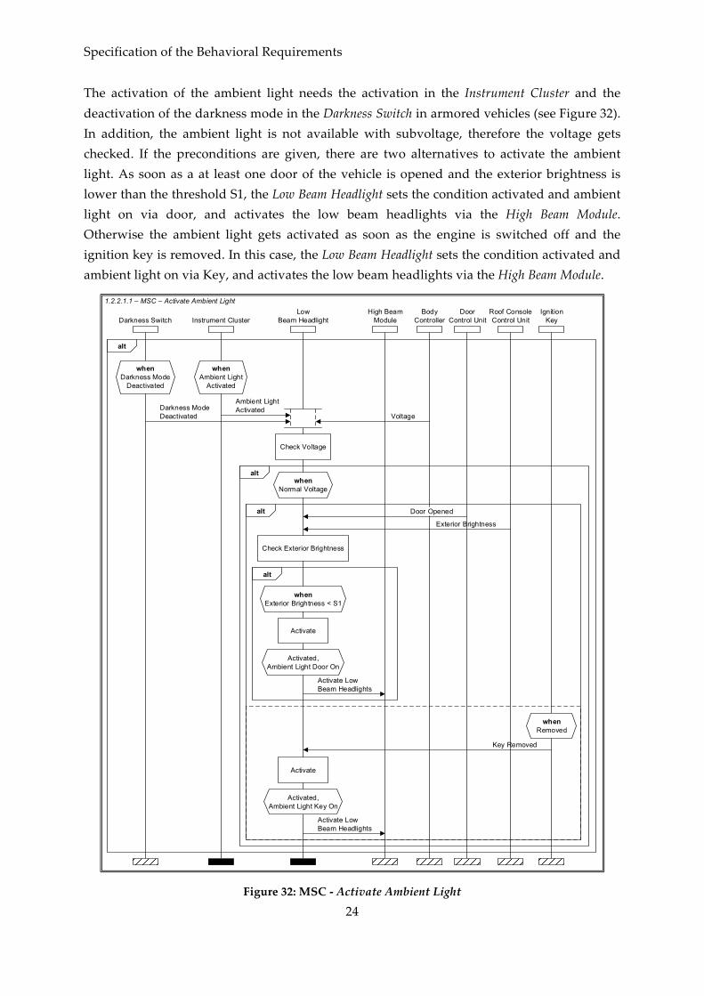
The activation of the ambient light needs the activation in the Instrument Cluster and the deactivation of the darkness mode in the Darkness Switch in armored vehicles (see Figure 32). In addition, the ambient light is not available with subvoltage, therefore the voltage gets checked. If the preconditions are given, there are two alternatives to activate the ambient light. As soon as a at least one door of the vehicle is opened and the exterior brightness is lower than the threshold S1, the Low Beam Headlight sets the condition activated and ambient light on via door, and activates the low beam headlights via the High Beam Module. Otherwise the ambient light gets activated as soon as the engine is switched off and the ignition key is removed. In this case, the Low Beam Headlight sets the condition activated and ambient light on via Key, and activates the low beam headlights via the High Beam Module.
High BeamModule
LowBeam HeadlightDarkness Switch
whenDarkness Mode
Deactivated
Activate
Activated,Ambient Light Door On
Activate LowBeam Headlights
BodyController
Exterior Brightness
Check Exterior Brightness
whenExterior Brightness < S1
alt
Darkness ModeDeactivated
Instrument Cluster
whenAmbient Light
Activated
Ambient LightActivated
alt
alt Door Opened
IgnitionKey
whenRemoved
Key Removed
Activate
Activated,Ambient Light Key On
Activate LowBeam Headlights
Check Voltage
Voltage
altwhen
Normal Voltage
1.2.2.1.1 – MSC – Activate Ambient LightDoor
Control UnitRoof ConsoleControl Unit
Figure 32: MSC -‐‑ Activate Ambient Light

Model-‐‑Based Engineering of an Automotive Adaptive Exterior Lighting System
25
When the daytime running light is activated in the Instrument Cluster and the engine gets started, the Low Beam Headlight sets the condition to activated and daytime running light on, and activates the low beam headlights via the High Beam Module (see Figure 33).
High BeamModule
LowBeam HeadlightIgnition Key
whenEngine Started
Instrument Cluster
whenDaytime Running Light
ActivatedEngine Started
Activate
Activated,Daytime Running Light On
Activate LowBeam Headlights
Daytime RunningLight Activated
1.2.2.1.2 – MSC – Activate Daytime Running Light
Figure 33: MSC -‐‑ Activate Daytime Running Light
The manual activation of the low beam headlights is triggered when the exterior light is switched on in the Rotary Light Switch (see Figure 34). This leads to the setting conditions activated and manual on in the Low Beam Headlight, and the activation via the High Beam Module.
High BeamModule
LowBeam Headlight
Activate
Activated,Manual On
Activate LowBeam Headlights
Rotary LightSwitch
whenExterior Light On
Exterior Light On
1.2.2.1.3 – MSC – Activate Low Beam Headlights Manual
Figure 34: MSC -‐‑ Activate Low Beam Headlights Manual

Specification of the Behavioral Requirements
26
When the Rotary Light Switch is in auto mode and the darkness mode is deactivated (in armored vehicles), the exterior brightness is checked by the Low Beam Headlight (see Figure 35). If the exterior brightness is lower than the threshold S1, the Low Beam Headlight sets the condition to activated and automatic on, and activates the low beam headlights via the High Beam Module.
High BeamModule
LowBeam Headlight
Rotary LightSwitch
whenAuto
Darkness Switch
whenDarkness Mode
DeactivatedAuto Mode
Activate
Activated,Automatic On
Activate LowBeam Headlights
Roof ConsoleControl Unit
Exterior Brightness
Check Exterior Brightness
whenExterior Brightness < S1
alt
Darkness Mode Deactivated
1.2.2.1.4 – MSC – Activate Low Beam Headlights Automatic
Figure 35: MSC -‐‑ Activate Low Beam Headlights Automatic

Model-‐‑Based Engineering of an Automotive Adaptive Exterior Lighting System
27
2.3.2.2 Deactivate Low Beam Headlights
For the deactivation of the low beam headlights, none of the possible activation conditions must be enabled. Therefore, the four activation scenarios (cf. Section 2.3.2.1) need a deactivation scenario (see Figure 36). Every time a deactivation scenario was passed, the conditions are checked and the low beam headlights either remain activated or get deactivated.
Deactivate Ambient
Light
Deactivate Daytime
Running Light
Deactivate Low Beam Headlights
Manual
Deactivate Low Beam Headlights
Automatic
Check Conditions and Switch Off
1.2.2.2 – hMSC – Deactivate Low Beam Headlights
Figure 36: hMSC -‐‑ Deactivate Low Beam Headlights
Figure 37 describes the four alternatives to deactivate the ambient light. In armored vehicles, the ambient light gets deactivated when the darkness mode is activated by the Darkness Switch. When the ambient light is deactivated in the Instrument Cluster, the Low Beam Headlight immediately deactivated both activation conditions. The third alternative only concerns the activation via door and is triggered by the Door Control Unit when all doors are closed. As long as the ambient light was activated by a key removal, the ambient light gets deactivated as soon as none of the actions open door, close door, insert or remove key occur within the next 30 seconds.

Specification of the Behavioral Requirements
28
30se
c<
30se
c
LowBeam HeadlightDarkness Switch Door Control UnitInstrument Cluster
whenAmbient LightDeactivated
Ambient LightDeactivated
alt
Door Opened
Ignition Key
whenRemoved
Key Removed
whenDarkness Mode
Activated
Darkness ModeActivated
Ambient Light Door Off,Ambient Light Key Off
whenAmbient Light Door On
All Doors Closed
Ambient Light Door Off
Ambient Light Door Off,Ambient Light Key Off
whenAmbient Light Key On
alt
Ambient Light Key On
< 30
sec
Door Closed
whenAmbient Light Key On
Ambient Light Key On
< 30
sec
whenAmbient Light Key On
Ambient Light Key On
whenInserted
Key Inserted< 30
sec
whenAmbient Light Key On
Ambient Light Key On
whenAmbient Light Key On
Ambient Light Key Off
1.2.2.2.1 – MSC – Deactivate Ambient Light
Figure 37: MSC -‐‑ Deactivate Ambient Light

Model-‐‑Based Engineering of an Automotive Adaptive Exterior Lighting System
29
The daytime running light gets deactivated either by deactivating the function in the Instrument Cluster or by removing the Ignition Key (see Figure 38).
LowBeam HeadlightIgnition Key
whenEngine Started
Instrument Cluster
whenDaytime Running Light
DeactivatedEngine Started
Daytime Running Light Off
Daytime RunningLight Deactivated
alt
whenRemoved
Key Removed
Daytime Running Light Off
1.2.2.2.2 – MSC – Deactivate Daytime Running Light
Figure 38: MSC -‐‑ Deactivate Daytime Running Light

Specification of the Behavioral Requirements
30
When the darkness mode gets activated in armored vehicles, the automatic condition of the Low Beam Headlight is set to off (see Figure 39). Otherwise the exterior brightness gets checked and the Low Beam Headlight deactivates the automatic condition 3 seconds after exceeding a threshold S2.
3sec
LowBeam Headlight
Rotary LightSwitch
whenAuto
Darkness Switch
whenDarkness Mode
DeactivatedAuto Mode
Automatic Off
Roof ConsoleControl Unit
Exterior Brightness
Check Exterior Brightness
whenExterior Brightness > S2
alt
Darkness Mode Deactivated
whenAuto
whenDarkness Mode
ActivatedAuto Mode
Darkness Mode Activated
alt
Automatic Off
1.2.2.2.4 – MSC – Deactivate Low Beam Headlights Automatic
Figure 39: MSC -‐‑ Deactivate Low Beam Headlights Automatic

Model-‐‑Based Engineering of an Automotive Adaptive Exterior Lighting System
31
To deactivate the low beam headlights manually, the driver needs to switch the Rotary Light Switch to off and the Low Beam Headlight is set to manual off (see Figure 40).
When one of the activation conditions of the low beam headlight was deactivated the conditions are checked, and only if all conditions are set to off, the Low Beam Headlight is set to deactivated and the low beam headlights get deactivated via the High Beam Module (see Figure 41).
LowBeam Headlight
Manual Off
Rotary LightSwitch
whenOff
Off Mode
1.2.2.2.3 – MSC – Deactivate Low Beam Headlights Manual
Figure 40: MSC -‐‑ Deactivate Low Beam Headlights Manual
LowBeam Headlight
High BeamModule
Deactivate
Deactivated
Deactivate LowBeam Headlights
whenAmbient Light Door Off,Ambient Light Key Off,
Daytime Running Light Off,Manual Off,
Automatic Off
1.2.2.2.5 – MSC – Check Conditions and Switch Off
Figure 41: MSC -‐‑ Check Conditions and Switch Off
2.3.2.3 Control Cornering Light
When the darkness mode is deactivated and direction blinking is requested by the Turning Light, the cornering light is activated by the Low Beam Headlight via the Body Controller if the vehicle drives slower than 10 km/h and there is no subvoltage (see Figure 42). If no more blinking is requested for 10 seconds the cornering light gets deactivated.

Specification of the Behavioral Requirements
32
10se
c
BodyController
LowBeam HeadlightDarkness Switch
whenDarkness Mode
Deactivated
ESPControl Unit
Darkness ModeDeactivated
alt
alt
Check VehicleSpeed
whenVehicle Speed < 10km/h,
Normal Voltage
Turning Light
whenDirection Blinking Right
Activated
Activate Right Cornering Light
Right Cornering Light Activated
Activate Right Cornering Light
whenVehicle Speed < 10km/h,
Normal Voltage
whenDirection Blinking Left
Activated
Activate Left Cornering Light
Left Cornering Light Activated
Activate Left Cornering Light
whenDirection Blinking Left
Deactivated,Direction Blinking Right
Deactivated
Deactivate Cornering Light
Cornering Light Deactivated
DeactivateCornering Light
Check Voltage
Voltage
1.2.2.3 – MSC – Control Cornering Light
Figure 42: MSC -‐‑ Control Cornering Light

Model-‐‑Based Engineering of an Automotive Adaptive Exterior Lighting System
33
2.3.3 Handle Overvoltage
To protect the illuminants from burning out in case of an occurring overvoltage, the Adaptive High Beam Headlight and the Low Beam Headlight must adapt the pulse width via the High Beam Module and the Body Controller (see Figure 43).
Adaptive HighBeam Headlight
whenActivated
BodyController
Voltage
LowBeam Headlight
High BeamModule
Pulse Width Modulation
Adapt Pulse Width
whenActivated
whenRight Cornering Light Activated
Check Voltage
whenOvervoltage
alt
Pulse Width Modulation
Adapt Pulse Width
whenOvervoltage
alt
alt
whenLeft Cornering Light Activated
Voltage
Check Voltage
Pulse Width Modulation
Adapt Pulse Width
whenOvervoltage
alt
Pulse Width Modulation
Adapt Pulse Width
whenOvervoltage
alt
1.2.3 – MSC – Handle Overvoltage
Figure 43: MSC -‐‑ Handle Overvoltage

Specification of the Behavioral Requirements
34
2.4 Control Turn Signal
The control of the turn signal (see Figure 44) comprises the activation and deactivation of the direction and tip blinking, and the control of the hazard warning light (see Section 2.4.3). The direction and tip blinking need to be differentiated between blinking left (see Section 2.4.1) or right (see Section 2.4.2). To activate one of the blinking directions, the other blinking direction must be deactivated. This represents the vertical neutral position of the pitman arm (cf. Section 2.2.2). However, controlling the hazard warning switch is independent from the actual blinking status.
Activate Direction Blinking Left
Activate Direction Blinking Right
ControlHazard Warning
Light
Deactivate Direction Blinking
Left
Deactivate Direction Blinking
Right
whenDirection Blinking Right Deactivated
Activate Tip Blinking Left
Activate Tip Blinking Right
whenDirection Blinking Right Activated
whenDirection Blinking Left Deactivated
whenDirection Blinking
Left Activated
whenHazard Warning Light
Deactivated
1.3 – hMSC – Control Turning Lights
Figure 44: hMSC -‐‑ Control Turning Lights

Model-‐‑Based Engineering of an Automotive Adaptive Exterior Lighting System
35
2.4.1 Direction Blinking Left
The activation of the left direction blinking is triggered by the Pitman Arm position (engaged) down (see Figure 45). This leads to the activation of the left direction indicators by the Turning Light via the Body Controller and the Door Control Unit with a pulse ratio bright to dark 1:1.
Turning LightBody
Controller
Direction Blinking LeftActivated
Left Indicators (Pulse Ratio 1:1)
Activate Left Indicators
Pitman Arm
whenDown
whenEngaged Down
Activate Direction Blinking Left
alt
Activate Direction Blinking Left
1.3.2 – MSC – Activate Direction Blinking Left
Left Indicators (Pulse Ratio 1:1)
Activate Left Indicators
DoorControl Unit
Figure 45: MSC -‐‑ Activate Direction Blinking Left
Specification of the Behavioral Requirements
36
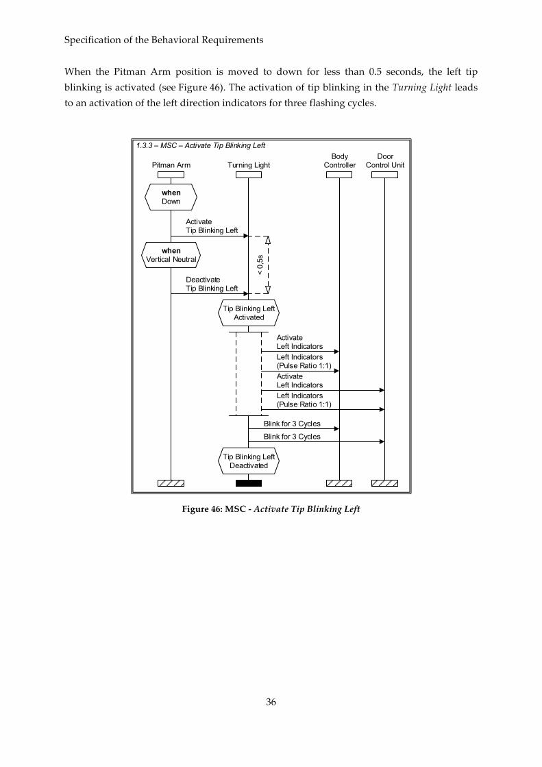
When the Pitman Arm position is moved to down for less than 0.5 seconds, the left tip blinking is activated (see Figure 46). The activation of tip blinking in the Turning Light leads to an activation of the left direction indicators for three flashing cycles.
Turning LightBody
Controller
Tip Blinking LeftActivated
Left Indicators (Pulse Ratio 1:1)
Activate Left Indicators
Pitman Arm
whenDown
whenVertical Neutral
Activate Tip Blinking Left
Deactivate Tip Blinking Left
< 0,
5s
Blink for 3 Cycles
Tip Blinking LeftDeactivated
1.3.3 – MSC – Activate Tip Blinking Left
Left Indicators (Pulse Ratio 1:1)
Activate Left Indicators
Blink for 3 Cycles
DoorControl Unit
Figure 46: MSC -‐‑ Activate Tip Blinking Left

Model-‐‑Based Engineering of an Automotive Adaptive Exterior Lighting System
37
To deactivate the left direction blinking, the Pitman Arm needs to be moved to the vertical neutral position (see Figure 47). The Turning Light switches its state to direction blinking left deactivated and deactivates the left direction indicators via the Body Controller and the Door Control Unit.
Turning LightBody
Controller
Direction Blinking LeftDeactivated
Deactivate Left Indicators
Pitman Arm
whenVertical Neutral
Deactivate Direction Blinking Left
1.3.7 – MSC – Deactivate Direction Blinking LeftDoor
Control Unit
Deactivate Left Indicators
Figure 47: MSC -‐‑ Deactivate Direction Blinking Left
Specification of the Behavioral Requirements
38
2.4.2 Direction Blinking Right
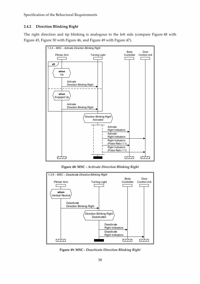
The right direction and tip blinking is analogous to the left side (compare Figure 48 with Figure 45, Figure 50 with Figure 46, and Figure 49 with Figure 47).
Turning LightBody
Controller
Direction Blinking RightActivated
Right Indicators (Pulse Ratio 1:1)
Activate Right Indicators
Pitman Arm
whenUp
whenEngaged Up
Activate Direction Blinking Right
alt
Activate Direction Blinking Right
1.3.4 – MSC – Activate Direction Blinking RightDoor
Control Unit
Activate Right Indicators
Right Indicators (Pulse Ratio 1:1)
Figure 48: MSC -‐‑ Activate Direction Blinking Right
Turning LightBody
Controller
Direction Blinking RightDeactivated
Deactivate Right Indicators
Pitman Arm
whenVertical Neutral
Deactivate Direction Blinking Right
1.3.6 – MSC – Deactivate Direction Blinking Right
Deactivate Right Indicators
DoorControl Unit
Figure 49: MSC -‐‑ Deactivate Direction Blinking Right

Model-‐‑Based Engineering of an Automotive Adaptive Exterior Lighting System
39
Turning LightBody
Controller
Tip Blinking RightActivated
Pitman Arm
whenUp
whenVertical Neutral
Activate Tip Blinking Right
Deactivate Tip Blinking Right
< 0,
5s
1.3.5 – MSC – Activate Tip Blinking Right
Right Indicators (Pulse Ratio 1:1)
Activate Right Indicators
Blink for 3 Cycles
Tip Blinking RightDeactivated
Right Indicators (Pulse Ratio 1:1)
Activate Right Indicators
Blink for 3 Cycles
DoorControl Unit
Figure 50: MSC -‐‑ Activate Tip Blinking Right
2.4.3 Hazard Warning Light
When the hazard warning light gets activated via the Hazard Warning Light Switch, the Turning Light activates both (left and right) direction indicators via the Body Controller and the Door Control Unit (see Figure 51). For energy saving reasons, the pulse ratio is reduced (bright to dark 1:2) when the Ignition Key is removed. To deactivate the hazard warning light, the Hazard Warning Light Switch must be switched off. The Turning Light sets its condition back to hazard warning light deactivated and direction blinking will be continued -‐‑ if activated (cf. Figure 44).

Specification of the Behavioral Requirements
40
Hazard WarningLight Switch
whenHazard Warning Light
Deactivated
whenHazard Warning Light
Activated
Turning Light
Hazard Warning Light Activated
BodyController
Hazard Warning LightActivated
Left Indicators (Pulse Ratio 1:2)
alt
IgnitionKey
whenRemoved
whenInserted
Key Removed
Right Indicators (Pulse Ratio 1:2)
Key Inserted
Left Indicators (Pulse Ratio 1:1)Right Indicators (Pulse Ratio 1:1)
Activate Left IndicatorsActivate Left Indicators
alt
Hazard Warning Light Deactivated
Hazard Warning LightDeactivated
Deactivate Left IndicatorsDeactivate Right Indicators
1.3.1 – MSC – Control Hazard Warning Light
DoorControl Unit
Activate Right IndicatorsActivate Right Indicators
Left Indicators (Pulse Ratio 1:2)Right Indicators (Pulse Ratio 1:2)
Left Indicators (Pulse Ratio 1:1)Right Indicators (Pulse Ratio 1:1)
Deactivate Left IndicatorsDeactivate Right Indicators
Figure 51: MSC -‐‑ Control Hazard Warning Light

Model-‐‑Based Engineering of an Automotive Adaptive Exterior Lighting System
41
2.5 Detect Faults
In addition to the handling of over-‐‑ and subvoltage (e.g., Section 2.3.3), the system provides the functionality to detect defective headlights (see Figure 52). The High Beam Module, the Body Controller and the Door Control Unit transmit the illuminant status to the Defect Detection, which checks the status and informs the Instrument Cluster about defective illuminants. Finally, the Instrument Cluster prioritizes the displayed information.
Instrument ClusterHigh Beam
Module
Prioritize the Display
Defect Detection
Check Illuminant Status
Illuminant Status
whenDefective Illuminant Detected
1.4 – MSC – Detect Faults
BodyController
DoorControl Unit
Illuminant Status
Illuminant Status
Figure 52: MSC -‐‑ Detect Faults

Specification of the Functional Design
42
3 Specification of the Functional Design
The model-‐‑based specification of a first functional design – as described in the following – comprises the combination of function networks and interface automata. The interaction between system functions and context functions is described by function network diagrams. Additionally, the internal behavior of the system functions is specified as interface automata. The context of the system and the interaction of the main system functions are described in Section 3.1, while the detailed descriptions of the main system functions are presented in Section 3.2, 3.3, and 3.4.
The specified functions of the ELS are subdivided into system and context functions. An overview is given in Table 2 and Table 3.
Table 2: Context Functions
Context Function Shapes
High Beam Module
Context Function
Body Controller
Use Ignition Key
Measure Exterior Brightness
ESP Control
Turn Rotary Light Switch
Set Instrument Cluster
Door Control
Move Pitman Arm
Detect Vehicles
Switch Darkness Mode
Switch Hazard Warning Light

Model-‐‑Based Engineering of an Automotive Adaptive Exterior Lighting System
43
Table 3: System Functions
System Function Level Shapes
Control Adaptive Exterior Lighting System 0
System Function
Control Headlights 1
Control High Beam Headlights 2
Activate Manual High Beam Headlights 3
Activate Adaptive High Beam Headlights 3
Deactivate Adaptive High Beam Headlights 3
Check Voltage 3
Adapt High Beam Headlights 3
Control Low Beam Headlights 2
Activate Low Beam Headlights 3
Activate Low Beam Headlights Manual 4
Activate Low Beam Headlights Automatic 4
Activate Daytime Running Light 4
Activate Ambient Light 4
Check Conditions 5
Activate by Door 5
Activate by Key 5
Deactivate Low Beam Headlights 3
Deactivate Low Beam Headlights Manual 4
Deactivate Low Beam Headlights Automatic 4
Deactivate Daytime Running Light 4
Deactivate Ambient Light 4
Check Conditions and Switch Off 4
Control Cornering Light 3
Check Conditions 4
Activate Left Cornering Light 4
Deactivate Left Cornering Light 4
Activate Right Cornering Light 4
Deactivate Rights Cornering Light 4
Handle Overvoltage 2
Control Turn Lights 1

Specification of the Functional Design
44
Activate Hazard Warning Light 2
Deactivate Hazard Warning Light 2
Activate Direction Blinking Left 2
Activate Tip Blinking Left 2
Deactivate Direction Blinking Left 2
Activate Direction Blinking Right 2
Activate Tip Blinking Right 2
Deactivate Direction Blinking Right 2
Detect Faults 1

Model-‐‑Based Engineering of an Automotive Adaptive Exterior Lighting System
45
3.1 Structure of the Functional Design
The Adaptive Exterior Lighting System comprises three main system functions Control Headlights, Control Turn Lights, and Detect Faults, which are represented by the abstract system function Control Adaptive Exterior Lighting System. The context of this abstract system function is described in a context diagram (cf. Figure 53). As modeled in the context diagram, the abstract system function interacts with the 12 context functions and interchanges 58 messages. For reasons of clarity and comprehensibility, several messages are summarized and labeled with an expression (e. g., the message Key {Inserted | Removed} represents the messages Key Inserted and Key Removed). However, condensed messages are separated on lower abstraction levels.
In the following, the meaning of all interactions between functions is usually described on the lowest abstraction level where no subdivision of functions occurs.
Control Adaptive Exterior Lighting SystemDetect Vehicles
Switch Hazard Warning Light
Move Pitman Arm
Body Controller
Measure Exterior Brightness
Turn Rotary Light Switch
Use Ignition KeyHigh Beam Module
SwitchDarkness Mode
ESP Control
Door Control
0 - Context
Set Instrument Cluster
Figure 53: Context Diagram

Specification of the Functional Design
46
The three main system functions Control Headlights, Control Turn Lights, and Detect Faults and their message interchanges are presented in Figure 54. In contrast to the context diagram, it is already noticeable how the messages between system functions and context functions are distributed on this level of abstraction. The messages for the activation and deactivation of the hazard warning light are only connected to the system function Control Turn Lights, for example. Moreover, the system function Control Turn Lights informs the system function Control Headlight about the status of the direction blinking.
Detect Faults
High Beam Module
Illum
inat
ion
Sta
tus
Control Turn Lights
Control Headlights
Detect VehiclesSwitchDarkness Mode
Door Control
Use Ignition Key
Switch Hazard Warning Light
Move Pitman Arm
Measure Exterior Brightness
Turn Rotary Light Switch
ESP Control
{Lef
t | R
ight
} Blin
king
Act
ivat
ed
{Lef
t | R
ight
} Blin
king
Dea
ctiv
ated
Body Controller
Illum
inat
ion
Sta
tus
Illum
inat
ion
Sta
tus
1 – Control Adaptive Exterior Lighting System
Set Instrument Cluster
Figure 54: Function Network Diagram – Control Adaptive Exterior Lighting System
In the following sections, the three main system function Control Headlights (Section 3.2), Control Turn Lights (Section 3.3) and Detect Faults (Section 3.4) with their interactions and internal behavior are described in detail.

Model-‐‑Based Engineering of an Automotive Adaptive Exterior Lighting System
47
3.2 Control Headlights
The control of the headlights (cf. Figure 55) is subdivided into the three system functions Control High Beam Headlights (cf. Section 3.2.1), Control Low Beam Headlights (cf. Section 3.2.2), and Handle Overvoltage (cf. Section 3.2.3). The control of the high beam headlights is triggered by the horizontal position of the pitman arm, the detection of vehicles, the vehicle speed, the position of the rotary light switch, and the voltage. Moreover, the activation and deactivation as well as the illumination areas of the high beam headlights are transmitted to the context function High Beam Module. To control the low beam headlights and the cornering light, the ambient and daytime running light settings, the vehicle speed, the position of the rotary light switch, the voltage, the exterior brightness, the status of the darkness mode and the doors as well as the information about the ignition key are used. Moreover, the status of the direction blinking from the system function Control Turn Lights (cf. Section 3.3) is required for the cornering light functionality. The system function Handle Overvoltage needs to get enabled by the system function Control High Beam Headlights or Control Low Beam Headlights.
High Beam Modul
Control Turn Lights
Detect Vehicles
SwitchDarkness Mode
Door Control
Use Ignition Key
Move Pitman Arm
Measure Exterior Brightness
Turn Rotary Light Switch
ESP Control
Push
ed
Pulle
d
Hor
izon
tal
Neu
tral
Body Controller
Set Instrument Cluster
Control High Beam Headlights
Control Low Beam Headlights
<<Enablement>>
Handle Overvoltage
Exte
rior L
ight
On
1.2 – Control Headlights
Figure 55: Function Network Diagram -‐‑ Control Headlights
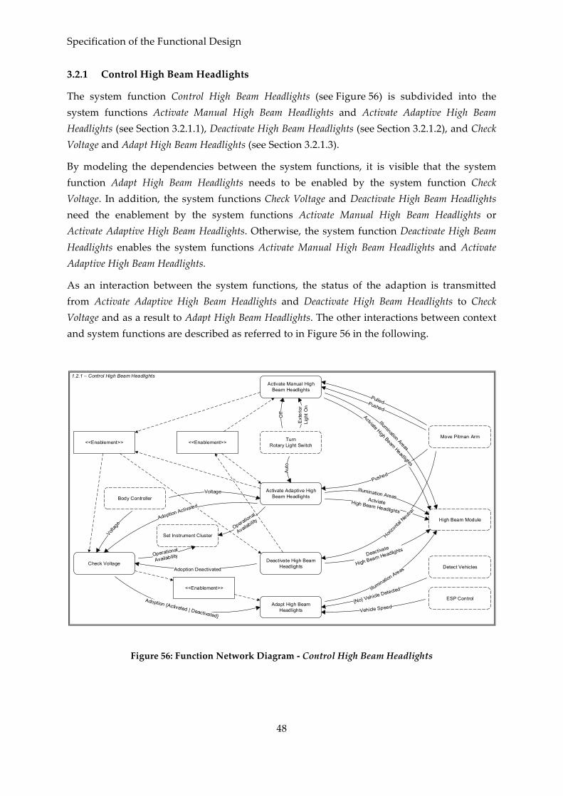
Specification of the Functional Design
48
3.2.1 Control High Beam Headlights
The system function Control High Beam Headlights (see Figure 56) is subdivided into the system functions Activate Manual High Beam Headlights and Activate Adaptive High Beam Headlights (see Section 3.2.1.1), Deactivate High Beam Headlights (see Section 3.2.1.2), and Check Voltage and Adapt High Beam Headlights (see Section 3.2.1.3).
By modeling the dependencies between the system functions, it is visible that the system function Adapt High Beam Headlights needs to be enabled by the system function Check Voltage. In addition, the system functions Check Voltage and Deactivate High Beam Headlights need the enablement by the system functions Activate Manual High Beam Headlights or Activate Adaptive High Beam Headlights. Otherwise, the system function Deactivate High Beam Headlights enables the system functions Activate Manual High Beam Headlights and Activate Adaptive High Beam Headlights.
As an interaction between the system functions, the status of the adaption is transmitted from Activate Adaptive High Beam Headlights and Deactivate High Beam Headlights to Check Voltage and as a result to Adapt High Beam Headlights. The other interactions between context and system functions are described as referred to in Figure 56 in the following.
High Beam Module
Detect Vehicles
Move Pitman ArmTurn Rotary Light Switch
ESP Control
Body Controller
Set Instrument Cluster
Off
Ext
erio
r Li
ght O
n
Activate Manual High Beam Headlights
Activate Adaptive High Beam Headlights
Check Voltage
Adapt High Beam Headlights
Deactivate High Beam Headlights
<<Enablement>>
<<Enablement>>
<<Enablement>>
Aut
o
Adoption Deactivated
1.2.1 – Control High Beam Headlights
Figure 56: Function Network Diagram -‐‑ Control High Beam Headlights

Model-‐‑Based Engineering of an Automotive Adaptive Exterior Lighting System
49
3.2.1.1 Activate High Beam Headlights
When the high beam headlights are activated by the context functions Move Pitman Arm and Turn Rotary Light Switch, the messages with fixed Illumination Areas of 220m and Activate High Beam Headlights are transmitted to the context function High Beam Module (Figure 57). The activation by the pitman arm includes the so-‐‑called flasher (cf. Section 2.2.2).
Pushed
1.2.1.1 – Activate Manual High Beam Headlights
Pulled?
Pushed?
Exterior Light On?
Off?
Activate;Activate HighBeam Headlights!
Illumination Areas (220m)!
Pulled Off Exterior Lights On
Activate HighBeam Headlights
IlluminationAreas
Figure 57: Interface Automaton -‐‑ Activate Manual High Beam Headlights
The activation of the adaptive high beam headlight is initialized by the pushed position of the pitman arm and the auto mode of the rotary light switch (see Figure 58). After activating the high beam headlights by the message Activate High Beam Headlights, transmitted to the context function High Beam Module, the voltage needs to be checked. The adaption of the high beam headlights is not available with subvoltage and the illumination area is set to default. Otherwise the adaption is activated and the Operational Availability of the adaptive high beam headlight is indicated by a symbol in the instrument cluster.
Auto?
Pushed? Auto?
Pushed?
Activate;
Illumination Areas (220m)!
Activate HighBeam Headlights!Voltage?
CheckVoltage; Normal Voltage;Subvoltage;
AdoptionActivated!Operational Availability!
Pushed
1.2.1.2 – Activate Adaptive High Beam Headlights
VoltageAuto
Activate HighBeam Headlights
IlluminationAreas
OperationalAvailability
AdoptionActivated
Figure 58: Interface Automaton -‐‑ Activate Adaptive High Beam Headlights

Specification of the Functional Design
50
3.2.1.2 Deactivate High Beam Headlights
When the pitman arm is moved again in the horizontal neutral position, the Adaptive High Beam Headlight is deactivated immediately (see Figure 59). Furthermore, the adaption is deactivated (if necessary) and the operational availability is updated in the instrument cluster.
HorizontalNeutral
1.2.1.3 – Deactivate High Beam Headlights
HorizontalNeutral? Deactivate;
Check AdoptionAcitvation;
Adoption Deactivated!
Operational Availability!
Deactivate HighBeam Headlights
Deactivate HighBeam Headlights!
AdoptionDeactivated
Figure 59: Interface Automaton -‐‑ Deactivate High Beam Headlights
3.2.1.3 Check Voltage and Adapt High Beam Headlights
Before the high beam headlight gets adapted, the voltage needs to be checked again (see Figure 60, cf. Figure 58).
Voltage
1.2.1.4 – Check Voltage
Voltage?
CheckVoltage;
NormalVoltage;
Operational Availability!
Subvoltage;
AdoptionDeactivated
AdoptionDeactivated?
AdoptionActivated?
DeactivateAdoption;
ActivateAdoption;
AdoptionActivated!
AdoptionDeactivated!
AdoptionActivated
AdoptionDeactivated
AdoptionActivated
Figure 60: Interface Automaton -‐‑ Check Voltage

Model-‐‑Based Engineering of an Automotive Adaptive Exterior Lighting System
51
When the adaption is activated and the context function Detect Vehicles recognizes the lights of an advancing vehicle, the activated high beam headlights are reduced to low beam headlights by reducing the illumination area to 65m in the context function High Beam Module. If no advancing vehicle is recognized any more, the high beam illumination is restored and the illumination area is calculated within 100m and 300m, depending on the vehicle speed. Otherwise, when the adoption is deactivated, the illumination areas are set to default 220m.
1.2.1.5 – Adapt High Beam Headlights
Adoption Deactivated?
VehicleDetected?
IlluminationAreas
VehicleSpeed
AdoptionDeactivated
AdoptionActivated
AdoptionActivated?
No VehicleDetected?
VehicleSpeed?
CheckVehicleSpeed;
CalculateIllumination
Areas;Illumination
Areas!
IlluminationAreas (65m)!
Illumination Areas (220m)!
VehicleDetected
No VehicleDetected
Figure 61: Interface Automaton -‐‑ Adapt High Beam Headlights

Specification of the Functional Design
52
3.2.2 Control Low Beam Headlights
In Figure 62, the subdivision of the system function Control Low Beam Headlights by introducing the system functions Activate Low Beam Headlights and Deactivate Low Beam Headlights as well as Control Cornering Light is presented. The activation of the low beam headlights can be done under several conditions (see Section 3.2.2.1). When the low beam headlights are activated, they could either be deactivated (see Section 3.2.2.2) or the cornering light could be controlled (see Section 3.2.2.3). The several activation conditions are transmitted from the system function Activate Low Beam Headlights to the system function Deactivate Low Beam Headlights. Moreover, the system function Control Cornering Light needs to get informed about the activation status of the low beam headlights and can be prevented by the system function Deactivate Low Beam Headlights or enabled by the system function Activate Low Beam Headlights. Again, a more detailed description of the interactions with the context functions is given in the following on a lower level of abstraction.
ActivateLow Beam Headlights
DeactivateLow Beam Headlights
ControlCornering Light
<<Enablement>>
SwitchDarkness Mode
Body Controller
ESP Control Control Turn Lights
<<Prevention>>
Set Instrument Cluster
Door Control
Measure Exterior Brightness
Use Ignition Key
High Beam Module
Turn Rotary Light Switch
Low Beam Headlights Deactivated
1.2.2 -Control Low Beam Headlights
Figure 62: Function Network Diagram -‐‑ Control Low Beam Headlights

Model-‐‑Based Engineering of an Automotive Adaptive Exterior Lighting System
53
3.2.2.1 Activate Low Beam Headlights
The activation of the low beam headlights can be done by the ambient light, the daytime running light, manually, or automatically (see Figure 63). Each activation ensures conditions without interdependencies to keep the low beam headlights active and needs to inform the system functions Control Cornering Light (cf. Section 3.2.2.3) and Deactivate Low Beam Headlights (cf. Section 3.2.2.2) about its status. In the following, the internal behavior of all possible activation functions and their interactions are described in detail.
DeactivateLow Beam Headlights
ControlCornering Light
SwitchDarkness Mode
Body Controller
Set Instrument Cluster
Door Control
Measure Exterior Brightness
Use Ignition Key
High Beam Module
Daytime Running Light Activated
Turn Rotary Light Switch
Activate Ambient Light
Activate Daytime Running Light
Activate Low Beam Headlights Manual
Activate Low Beam Headlights Automatic
1.2.2.1 – Activate Low Beam Headlights
ExteriorBrightness
Figure 63: Function Network Diagram -‐‑ Activate Low Beam Headlights

Specification of the Functional Design
54
The manual activation of the low beam headlights is triggered when the exterior light is switched on (see Figure 64). This leads to the transmission of the messages Activate Low Beam Headlights to the context function High Beam Module and Low Beam Headlights Activated to the system function Control Cornering Light. Moreover, the system function Deactivate Low Beam Headlight gets informed about the manual activation.
Exterior LightOn
Activate LowBeam Headlights
1.2.2.1.3 – Activate Low Beam Headlights Manual
Exterior LightOn?
Activate LowBeam Headlights!
Low BeamHeadlights Activated
ManualOn
Low BeamHeadlights Activated!
ManualOn!
Figure 64: Interface Automaton -‐‑ Activate Low Beam Headlights Manual
When the rotary light switch is in auto mode and the darkness mode is deactivated (in armored vehicles), the exterior brightness from the context function Measure Exterior Brightness is checked (see Figure 65). If the exterior brightness is lower than a threshold S1, the low beam headlights are activated and automatic is set to on.
DarknessmodeDeactivated
Activate LowBeam Headlights
1.2.2.1.4 – Activate Low Beam Headlights Autoamtic
ExteriorBrightness? Check Exterior Brightness;
Brightness < S1;
DarknessmodeDeactivated?
Activate LowBeam Headlights!
Brightness >= S1
Auto ExteriorBrightness
Low BeamHeadlights Activated
Auto?
AutomaticOn
Low BeamHeadlights Activated!
AutomaticOn!
Figure 65: Interface Automaton -‐‑ Activate Low Beam Headlights Automatic

Model-‐‑Based Engineering of an Automotive Adaptive Exterior Lighting System
55
When the daytime running light is activated by the context function Set Instrument Cluster and the engine gets started, the low beam headlights are activated and daytime running light is on (see Figure 66).
1.2.2.1.2 – Activate Daytime Running Light
Daytime RunningLight Activated
Activate LowBeam Headlights
Daytime RunningLight Activated?
EngineStarted?
Low BeamHeadlights Activated
Daytime RunningLight On
Low BeamHeadlights Activated!
Daytime RunningLight On!
EngineStarted
Low BeamHeadlights Activated!
Figure 66: Interface Automaton -‐‑ Activate Daytime Running Light
The system function Activate Ambient Light is divided into three system functions again (see Figure 67). First, the conditions for an activation need to be checked, and afterwards the ambient light could either be activated by door or by key.

Specification of the Functional Design
56
DeactivateLow Beam Headlights
ControlCornering Light
SwitchDarkness Mode
Body Controller
DarknessmodeDeactivated
Set Instrument Cluster
Ambient LightActivated
Voltage
Door Control
Measure Exterior Brightness Use Ignition Key
High Beam Module
Check Conditions
Activate by Door Activate by Key
1.2.2.1.1 – Activate Ambient Light
Figure 67: Function Network Diagram -‐‑ Activate Ambient Light
The activation of the ambient light needs the activation in the instrument cluster and the deactivation of the darkness mode in armored vehicles (see Figure 68). In addition, the ambient light is not available with subvoltage, therefore the voltage gets checked.

Model-‐‑Based Engineering of an Automotive Adaptive Exterior Lighting System
57
Ambient LightActivated
ConditionsAccepted
1.2.2.1.1.1 – Check Conditions
DarknessmodeDeactivated?
Ambient LightActivated?
Voltage?
Check Voltage;ContitionsAccepted!
No Normal Voltage;
Normal Voltage;
Voltage DarknessmodeDeactivated
Figure 68: Interface Automaton -‐‑ Check Conditions
KeyRemoved
Activate LowBeam Headlights
1.2.2.1.1.3 – Activate by Key
ConditionsAccepted?
Activate LowBeam Headlights!
Low BeamHeadlights Activated
Low BeamHeadlightsActivated!
Ambient Light Key On!
KeyRemoved?
Ambient Light Key On
ConditionsAccepted
Figure 69: Interface Automaton -‐‑ Activate by Key
If the preconditions are given, there are two alternatives to activate the ambient light. As soon as at least one door of the vehicle is opened and the exterior brightness is lower than the threshold S1, the low beam headlights are activated and the ambient light is on via door (see Figure 70). Otherwise, the ambient light gets activated as soon as the engine is switched off and the ignition key is removed. In this case, the low beam headlights are activated and the ambient light is on via Key (see Figure 69).
ExteriorBrightness
Activate LowBeam Headlights
1.2.2.1.1.2 – Activate by Door
ConditionsAccepted?
Activate LowBeam Headlights!
Low BeamHeadlights Activated
Low BeamHeadlightsActivated!
Ambient Light Door On!
DoorOpened?
ExteriorBrightness?
Check ExteriorBrightness;
ExteriorBrightness < S1
Exterior Brightness >= S1
Ambient Light Door On
ConditionsAccepted
DoorOpened
Figure 70: Interface Automaton -‐‑ Activate by Door
3.2.2.2 Deactivate Low Beam Headlights
For the deactivation of the low beam headlights, none of the possible activation conditions must be enabled. Therefore, the four activation functions (cf. Section 3.2.2.1) need a deactivation function (see Figure 71). Every time a deactivation function is completed, the

Specification of the Functional Design
58
conditions are checked and the low beam headlights either remain activated or become deactivated by the system function Check Conditions and Switch Off.
ActivateLow Beam Headlights
ControlCornering Light
SwitchDarkness ModeSet Instrument Cluster Door Control Measure Exterior
BrightnessUse Ignition Key
High Beam Module
Turn Rotary Light Switch
Off
Low B
eam
Headlights
Activated
DeactivateAmbient Light
Deactivate Daytime Running Light
Deactivate Low Beam Headlights Manual
Check Conditions and Switch Off
Deactivate Low Beam Headlights Automatic
1.2.2.2 – Deactivate Low Beam Headlights
Figure 71: Function Network Diagram -‐‑ Deactivate Low Beam Headlights
To deactivate the low beam headlights manually, the driver needs to switch the rotary light switch to off and the low beam headlights are Manual Off (see Figure 72).
When the darkness mode gets activated in armored vehicles, the automatic condition is set to off (see Figure 73). Otherwise, the exterior brightness gets checked and the low beam headlights are deactivated after exceeding a threshold S2.

Model-‐‑Based Engineering of an Automotive Adaptive Exterior Lighting System
59
Off
1.2.2.2.3 – DeactivateLow Beam Headlights
Manual
ManualOn?
ManualOff
ManualOff!
ManualOn
Off?
Figure 72: Interface Automaton -‐‑ Deactivate Low Beam Headlights Manual
DarknessmodeDeactivated
AutomaticOff
1.2.2.2.4 – Deactivate Low Beam Headlights Automatic
ExteriorBrightness?
Check ExteriorBrightness;
Brightness > S2;
DarknessmodeDeactivated?
Brightness <= S2;
Auto ExteriorBrightness
Auto?
AutomaticOn
AutomaticOff!
DarknessmodeActivated
DarknessmodeActivated?
Auto?
Figure 73: Interface Automaton -‐‑ Deactivate Low Beam Headlights Automatic
The daytime running light gets deactivated either by deactivating the function in the instrument cluster or by removing the ignition Key (see Figure 74).
1.2.2.2.2 – Deactivate Daytime Running Light
Daytime RunningLight Deactivated
Daytime RunningLight Off
Daytime RunningLight Deactivated?
EngineStarted?
Daytime RunningLight On
Daytime RunningLight Off!
EngineStarted
Key Removed?
Daytime RunningLight On?
KeyRemoved
Figure 74: Interface Automaton -‐‑ Deactivate Daytime Running Light
Figure 75 describes the four alternatives to deactivate the ambient light. In armored vehicles, the ambient light gets deactivated when the darkness mode is activated. When the ambient light is deactivated by the context function Set Instrument Cluster, the Low Beam Headlight immediately deactivated both activation conditions (door and key). The third alternative only concerns the activation via door and is triggered by the context function Door Control when all doors are closed. As long as the ambient light was activated by a key removal, the ambient light gets deactivated as soon as none of the actions open door, close door, insert or remove key occur within the next 30 seconds.

Specification of the Functional Design
60
1.2.2.2.1 – Deactivate Ambient Light
Ambient Light Deactivated
Ambient Light{Door | Key} Off
DarknessmodeActivated
Ambient Light Door Off!
All DoorsClosed
Darknessmode Activated?
Ambient Light Door On
Ambient Light Key Off!
Ambient Light Deactivated?
Ambient Light Door On?
All DoorsClosed?
Ambient Light Key On?
Key Removed?
Key Inserted?
Door Closed?
Door Opened?
Check Time;
Ambient Light Key Off! Time > 30sec
Time <= 30sec
Door{Opened | Closed}
Key {Removed | Inserted}
Figure 75: Interface Automaton -‐‑ Deactivate Ambient Light
If one of the activation conditions of the low beam headlight was deactivated the conditions are checked, and only if all conditions are set to off, the low beam headlights get deactivated (see Figure 76). For reasons of clarity and comprehensibility the messages Ambient Light Door Off, Ambient Light Key Off, Daytime Running Light Off, Automatic Off, and Manual Off are modeled as a sequence, but the order is interchangeable.
Low BeamHeadlights Activated
1.2.2.2.5 – Check Conditions and Switch Off
Daytime RunningLight Off?
AutomaticOff?Manual Off?
Low BeamHeadlights Activated?
Ambient Light Key Off
AutomaticOff
Daytime RunningLight Off
Ambient Light Key Off?
DeactivateLow Beam Headlights!
Low BeamHeadlights Deactivated!
Ambient Light Door Off?
Ambient Light Door Off
ManualOff
Deactivate LowBeam Headlights
Low BeamHeadlights Deactivated
Figure 76: Interface Automaton -‐‑ Check Conditions and Switch Off

Model-‐‑Based Engineering of an Automotive Adaptive Exterior Lighting System
61
3.2.2.3 Control Cornering Light
The system function Control Cornering Light is divided into the five system functions Check Conditions, Activate Left Cornering Light, Activate Right Cornering Light, Deactivate Left Cornering Light, and Deactivate Right Cornering Light (see Figure 77). The activation and deactivation is triggered by the system function Control Turn Lights (cf. Section 3.3) and for the activation it needs to receive the message Conditions Accepted by the system function Check Conditions.
ActivateLow Beam Headlights
DeactivateLow Beam Headlights
SwitchDarkness Mode
Volta
ge
Body Controller
ESP Control
Control Turn Lights
Check Conditions
Activate Left Cornering Light
Activate Right Cornering Light
Deactivate Left Cornering Light
Deactivate Right Cornering Light
1.2.2.3 – Control Cornering Light
Figure 77: Function Network Diagram -‐‑ Control Cornering Light
When the low beam headlights are activated, the darkness mode is deactivated. The conditions for an activation are met if the vehicle drives slower than 10 km/h and there is no subvoltage (see Figure 78).
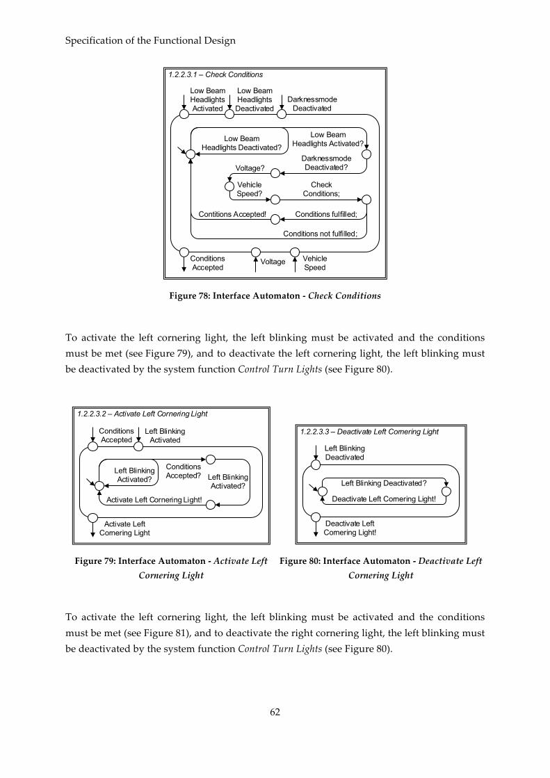
Specification of the Functional Design
62
Low BeamHeadlightsActivated
ConditionsAccepted
1.2.2.3.1 – Check Conditions
DarknessmodeDeactivated?Voltage?
VehicleSpeed?
CheckConditions;
Low BeamHeadlights Activated?Low Beam
Headlights Deactivated?
Contitions Accepted!
Conditions not fulfilled;
Conditions fulfilled;
Low BeamHeadlightsDeactivated
DarknessmodeDeactivated
Voltage VehicleSpeed
Figure 78: Interface Automaton -‐‑ Check Conditions
To activate the left cornering light, the left blinking must be activated and the conditions must be met (see Figure 79), and to deactivate the left cornering light, the left blinking must be deactivated by the system function Control Turn Lights (see Figure 80).
ConditionsAccepted
Activate LeftCornering Light
1.2.2.3.2 – Activate Left Cornering Light
Left BlinkingActivated?
Activate Left Cornering Light!
ConditionsAccepted?Left Blinking
Activated?
Left BlinkingActivated
Figure 79: Interface Automaton -‐‑ Activate Left Cornering Light
Deactivate Left Cornering Light!
1.2.2.3.3 – Deactivate Left Cornering Light
Left Blinking Deactivated?
Deactivate Left Cornering Light!
Left BlinkingDeactivated
Figure 80: Interface Automaton -‐‑ Deactivate Left Cornering Light
To activate the left cornering light, the left blinking must be activated and the conditions must be met (see Figure 81), and to deactivate the right cornering light, the left blinking must be deactivated by the system function Control Turn Lights (see Figure 80).

Model-‐‑Based Engineering of an Automotive Adaptive Exterior Lighting System
63
ConditionsAccepted
Activate Right Cornering Light
1.2.2.3.4 – Activate Right Cornering Light
Right BlinkingActivated?
Activate Right Cornering Light!
ConditionsAccepted?Right Blinking
Activated?
Right BlinkingActivated
Figure 81: Interface Automaton -‐‑ Activate Right Cornering Light
Deactivate RightCornering Light!
1.2.2.3.5 – Deactivate Right Cornering Light
Right Blinking Deactivated?
Deactivate Right Cornering Light!
Right BlinkingDeactivated
Figure 82: Interface Automaton -‐‑ Deactivate Right Cornering Light
3.2.3 Handle Overvoltage
To protect the illuminants from burning out in case of an occurring overvoltage, the pulse width gets adapted via the High Beam Module and the Body Controller (see Figure 83).
Voltage?
Voltage
Check Voltage;
AdaptPulse Width!
Adapt Pulse Width
Overvoltagedetected;
Normal voltage;
1.2.3 – Handle Overvoltage
Figure 83: Interface Automaton -‐‑ Handle Overvoltage
3.3 Control Turn Signal
The system function Control Turn Lights is subdivided into the eight system functions Activate Hazard Warning Light, Deactivate Hazard Warning Light, Activate Tip Blinking Right, Activate Direction Blinking Right, Deactivate Direction Blinking Right, Activate Tip Blinking Left, Activate Direction Blinking Left, and Deactivate Direction Blinking Left (cf. Figure 84 and Figure 85). Compared to Figure 54 in Section 3.1, the interactions with the context functions are distributed and the system function Control Headlights receives the status of direction blinking from several system functions (cf. Figure 84). For reasons of clarity and comprehensibility, there are two overviews of the system function Control Turn Lights. In

Specification of the Functional Design
64
Figure 84, only the interactions and messages between system and context functions are presented, and in Figure 85 an overview of the dependencies of the system functions is given.
Basically, the messages for activation and deactivation of a direction indicator are transmitted to the context functions Door Control and Body Controller, which are responsible for the physical control of all direction indicators. The message Pulse Ratio is used to adjust the bright to dark ratio of each direction indicator.
To control the hazard warning light, the system functions Activate Hazard Warning Light and Deactivate Hazard Warning Light receive the messages containing the current settings of the hazard warning light switch and the status of the ignition key. As an output the Left and Right Blinking is either activated or deactivated. The internal behavior of these two system functions is presented in Section 3.3.3. The other six system functions on this level of abstraction control the left (cf. Section 3.3.1) and right (cf. Section 3.3.2) turn signals.
Control Headlights
Door Control
Use Ignition KeySwitch Hazard Warning Light
Move Pitman Arm
Body Controller
Activate Hazard Warning Light
Deactivate Hazard Warning Light
ActivateDirection Blinking Left
Activate Direction Blinking Right
ActivateTip Blinking Left
Activate Tip Blinking Right
DeactivateDirection Blinking Left
DeactivateDirection Blinking Right
1.1 – Control Turn Lights (Messages)
Figure 84: Function Network Diagram -‐‑ Control Turn Lights (Messages)
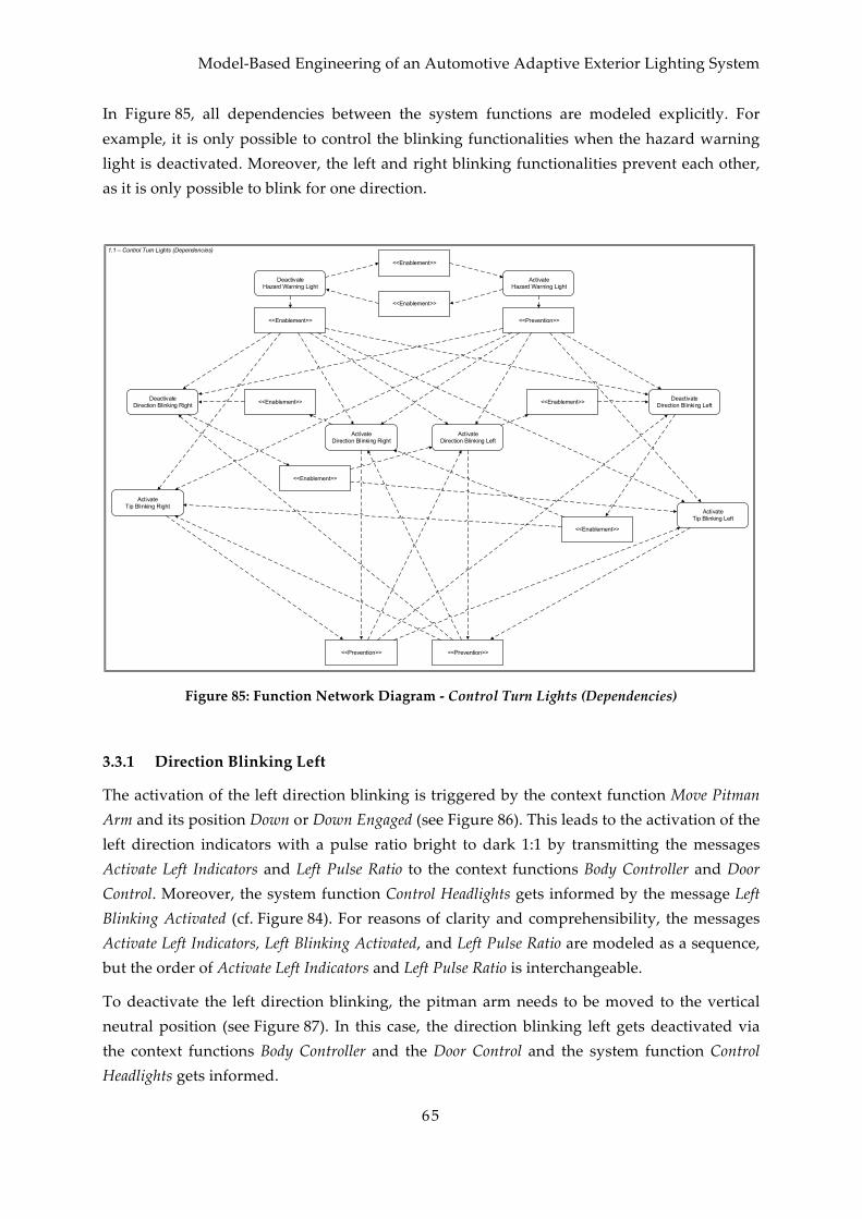
Model-‐‑Based Engineering of an Automotive Adaptive Exterior Lighting System
65
In Figure 85, all dependencies between the system functions are modeled explicitly. For example, it is only possible to control the blinking functionalities when the hazard warning light is deactivated. Moreover, the left and right blinking functionalities prevent each other, as it is only possible to blink for one direction.
Activate Hazard Warning Light
Deactivate Hazard Warning Light
ActivateDirection Blinking Left
Activate Direction Blinking Right
ActivateTip Blinking Left
Activate Tip Blinking Right
DeactivateDirection Blinking Left
DeactivateDirection Blinking Right <<Enablement>>
<<Prevention>>
<<Enablement>>
<<Prevention>><<Enablement>>
<<Prevention>>
<<Enablement>>
<<Enablement>>
<<Enablement>>
<<Enablement>>
1.1 – Control Turn Lights (Dependencies)
Figure 85: Function Network Diagram -‐‑ Control Turn Lights (Dependencies)
3.3.1 Direction Blinking Left
The activation of the left direction blinking is triggered by the context function Move Pitman Arm and its position Down or Down Engaged (see Figure 86). This leads to the activation of the left direction indicators with a pulse ratio bright to dark 1:1 by transmitting the messages Activate Left Indicators and Left Pulse Ratio to the context functions Body Controller and Door Control. Moreover, the system function Control Headlights gets informed by the message Left Blinking Activated (cf. Figure 84). For reasons of clarity and comprehensibility, the messages Activate Left Indicators, Left Blinking Activated, and Left Pulse Ratio are modeled as a sequence, but the order of Activate Left Indicators and Left Pulse Ratio is interchangeable.
To deactivate the left direction blinking, the pitman arm needs to be moved to the vertical neutral position (see Figure 87). In this case, the direction blinking left gets deactivated via the context functions Body Controller and the Door Control and the system function Control Headlights gets informed.

Specification of the Functional Design
66
Down?
Down
ActivateLeft Indicators!
Left BlinkingActivated!
Left PulseRatio (1:1)!
Down Engaged
ActivateLeft Indicators
Left BlinkingActivated
Left PulseRatio
Down Engaged?
1.1.3 – Activate Direction Blinking Left
Figure 86: Interface Automaton -‐‑ Activate Direction Blinking Left
Vertical Neutral?
VerticalNeutral
DeactivateLeft Indicators!
Left Blinking Deactivated!
DeactivateLeft Indicators
Left BlinkingDeactivated
1.1.5 – Deactivate Direction Blinking Left
Figure 87: Interface Automaton -‐‑ Deactivate Direction Blinking Left
When the pitman arm position is moved to down for less than 0.5 seconds, the left tip blinking is activated (see Figure 88). The activation of tip blinking leads to an activation of the left direction indicators for three flashing cycles. Just as in Figure 86, the messages Activate Left Indicators, Left Blinking Activated, and Left Pulse Ratio are modeled as a sequence for reasons of clarity and comprehensibility, but the order of Activate Left Indicators and Left Pulse Ratio is interchangeable.
Down?
Down
ActivateLeft Indicators!
Left BlinkingActivated!
Left PulseRatio (1:1)!
Vertical Neutral
ActivateLeft Indicators
Left BlinkingActivated
Left PulseRatio
1.1.4 – Activate Tip Blinking Left
Vertical Neutral? Check Down Duration;
Duration > 0,5s;
Figure 88: Interface Automaton -‐‑ Activate Tip Blinking Left

Model-‐‑Based Engineering of an Automotive Adaptive Exterior Lighting System
67
3.3.2 Direction Blinking Right
The right direction and tip blinking is analogous to the left side (compare Figure 89 with Figure 86, Figure 90 with Figure 88, and Figure 87 with Figure 91).
Up?
Up
ActivateRight Indicators!
Right BlinkingActivated!
Right PulseRatio (1:1)!
Up Engaged
ActivateRight Indicators
Right BlinkingActivated
Right PulseRatio
Up Engaged?
1.1.6 – Activate Direction Blinking Right
Figure 89: Interface Automaton -‐‑ Activate Direction Blinking Right
Up?
Up
ActivateRight Indicators!
Right BlinkingActivated!
Right PulseRatio (1:1)!
Vertical Neutral
ActivateRight Indicators
Right BlinkingActivated
Right PulseRatio
1.1.7 – Activate Tip Blinking Right
Vertical Neutral? Check Up Duration;
Duration > 0,5s;
Figure 90: Interface Automaton -‐‑ Activate Tip Blinking Right
Vertical Neutral?
VerticalNeutral
DeactivateRight Indicators!
Right Blinking Deactivated!
DeactivateRight Indicators
Right BlinkingDeactivated
1.1.8 – Deactivate Direction Blinking Right
Figure 91: Interface Automaton -‐‑ Deactivate Direction Blinking Right

Specification of the Functional Design
68
3.3.3 Hazard Warning Light
When the hazard warning light gets activated via the context function Switch Hazard Warning Light (cf. Figure 84), the left and right direction indicators get activated via the context functions Body Controller and Door Control (see Figure 92). Again, the system function Control Headlight is informed by the messages Left Blinking Activated and Right Blinking Activated. In Figure 92, the interchangeability of messages concerning the left and right indicators is modeled explicitly. For energy saving reasons, the pulse ratio is reduced (bright to dark 1:2) when the ignition key is removed.
Hazard Warning LightActivated?
ActivateLeft Indicators
KeyInserted
ActivateLeft Indicators!
ActivateRight Indicators!
ActivateLeft Indicators!
ActivateRight Indicators!
Left BlinkingActivated!
Right BlinkingActivated!
Left BlinkingActivated!
Right BlinkingActivated!
KeyRemoved?
Left PulseRatio (1:2)!
Right PulseRatio (1:2)!
Left PulseRatio (1:2)!
Right PulseRatio (1:2)!
Left PulseRatio (1:1)!
Right PulseRatio (1:1)!
Left PulseRatio (1:1)!
Right PulseRatio (1:1)!
KeyInserted?
KeyRemoved
Hazard Warning LightActivated
ActivateRight Indicators
Left BlinkingActivated
Right BlinkingActivated
Left PulseRatio
Right PulseRatio
1.1.1 – Activate Hazard Warning Light
Figure 92: Interface Automaton -‐‑ Activate Hazard Warning Light
The deactivation is also triggered by the context function Switch Hazard Warning Light (cf. Figure 84), and the left and right direction indicators get deactivated via the context functions Body Controller and Door Control (see Figure 93). Again, the system function Control Headlight is informed by the messages Left Blinking Deactivated and Right Blinking Deactivated.

Model-‐‑Based Engineering of an Automotive Adaptive Exterior Lighting System
69
Hazard Warning LightDeactivated?
DeactivateLeft Indicators
DeactivateLeft Indicators!
DeactivateRight Indicators!
DeactivateLeft Indicators!
DeactivateRight Indicators!
Left IndicatorsDeactivated!
Right IndicatorsDeactivated!
Left IndicatorsDeactivated!
Right IndicatorsDeactivated!
Hazard Warning LightDeactivated
DeactivateRight Indicators
Left BlinkingDeactivated
Right BlinkingDeactivated
1.1.2 – Deactivate Hazard Warning Light
Figure 93: Interface Automaton -‐‑ Deactivate Hazard Warning Light
3.4 Defect Faults
The system function Detect Faults uses the message Illuminant Status from the context functions Body Controller and High Beam Module to check these statuses and to identify defective illuminants. The information about defective illuminants is then transmitted to the context function Set Instrument Cluster (cf. Figure 54 in Section 3.1). This behavior is presented in Figure 94.
Illumination Status?
Defective IlluminantInformation
Defective IlluminantInformation!
IlluminantStatus
Check IlluminantStatus;
DefectiveIlluminant Detected;
No Defective Illuminant Detected;
1.3 – Detect Faults
Figure 94: Interface Automaton -‐‑ Detect Faults

References
70
4 References
Beetz K, Böhm DW (2012) Challenges in Engineering for Software-‐‑Intensive Embedded Systems. In: Pohl K, Hönninger H, Achatz R, Broy M (eds) Model-‐‑Based Engineering of Embedded Systems. Springer Berlin Heidelberg, pp 3–14
Brinkkemper S, Pachidi S (2010) Functional Architecture Modeling for the Software Product Industry. In: Babar MA, Gorton I (eds) Software Architecture. Springer Berlin Heidelberg, pp 198–213
Daun M, Tenbergen B, Weyer DT (2012) Requirements Viewpoint. In: Pohl K, Hönninger H, Achatz R, Broy M (eds) Model-‐‑Based Engineering of Embedded Systems. Springer Berlin Heidelberg, pp 51–68
Daun M, Weyer T, Pohl K (2014) Validating the Functional Design of Embedded Systems against Stakeholder Intentions: Proceedings of the 2nd International Conference on Model-‐‑Driven Engineering and Software Development 2014. SCITEPRESS -‐‑ Science and and Technology Publications, pp 333–339
De Alfaro L, Henzinger TA (2001) Interface Automata. Proceedings of the 8th European Software Engineering Conference Held Jointly with 9th ACM SIGSOFT International Symposium on Foundations of Software Engineering. ACM, New York, NY, USA, pp 109–120
Houdek F (2013) System Requirements Specification Automotive System Cluster (ELC and ACC). Technical University of Munich
ITU (2011) Recommendation ITU-‐‑T Z.120 : Message Sequence Chart (MSC). International Telecommunication Union
Jantsch A, Sander I (2000) On the roles of functions and objects in system specification. Proceedings of the Eighth International Workshop on Hardware/Software Codesign, 2000. CODES 2000. pp 8–12
Pretschner A, Broy M, Kruger IH, Stauner T (2007) Software Engineering for Automotive Systems: A Roadmap. 2007 Future of Software Engineering. IEEE Computer Society, Washington, DC, USA, pp 55–71
Sikora E, Tenbergen B, Pohl K (2012) Industry needs and research directions in requirements engineering for embedded systems. Requirements Eng 17:57–78. doi: 10.1007/s00766-‐‑011-‐‑0144-‐‑x
Weber M, Weisbrod J (2002) Requirements engineering in automotive development-‐‑experiences and challenges. IEEE Joint International Conference on Requirements Engineering, 2002. Proceedings. pp 331–340


Previously published ICB -‐‑ Research Reports
2015
No 63 (January)
Schauer, Carola; Schauer, Hanno: „IT an allgemeinbildenden Schulen: Bildungsgegenstand und -‐‑infrastruktur – Auswertung internationaler empirischer Studien und Literaturanalyse“
2014
No 62 (October)
Köninger, Stephan; Heß, Michael: „Konzeption und Implementierung eines Software-‐‑Werkzeuges zur multiperspektivischen Bewertung innovativer Produkte, Projekte und Dienstleistungen im Projekt Hospital Engineering
No 61 (May)
Schauer, Carola; Frank, Ulrich: “Wirtschaftsinformatik an Schulen. Status und Desiderata mit Fokus auf Nordrhein-‐‑Westfalen“
No 60 (May)
Heß, Michael: “Multiperspektivische Dokumentation und Informationsbedarfsanalyse kardiologischer Prozesse sowie Konzeptualisierung ausgewählter medizinischer Ressourcentypen im Projekt Hospital Engineering“
No 59 (May)
Goedicke, Michael; Kurt-‐‑Karaoglu, Filiz; Schwinning, Nils; Schypula, Melanie; Striewe, Michael: “Zweiter Jahresbericht zum Projekt „Bildungsgerechtigkeit im Fokus“ (Teilprojekt 1.2 -‐‑ „Blended Learning“) an der Fakultät für Wirtschaftswissenschaften“
No 58 (March)
Breitschwerdt, Rüdiger; Heß, Michael: “Konzeption eines Bezugsrahmens zur Analyse und Entwicklung von Geschäftsmodellen mobiler Gesundheitsdienstleistungen – Langfassung“
No 57 (March)
Heß, Michael; Schlieter, Hannes (Hrsg.): “Modellierung im Gesundheitswesen – Tagungsband des Workshops im Rahmen der »Modellierung 2014«“
2013
No 56 (July)
Svensson, Richard Berntsson; Berry,Daniel M.; Daneva, Maya; Doerr, Joerg; Espana, Sergio; Herrmann, Andrea; Herzwurm, Georg; Hoffmann, Anne; Pena, Raul Mazo; Opdahl, Andreas L.; Pastor, Oscar; Pietsch,Wolfram; Salinesi, Camille; Schneider, Kurt; Seyff, Norbert; van de Weerd, Inge; Wieringa, Roel; Wnuk, Krzysztof (Eds.): “19th International Working Conference on Requirements Engineering: Foundation for Software Quality (REFSQ 2013). Proceedings of the REFSQ 2013 Workshops CreaRE, IWSPM, and RePriCo, the REFSQ 2013 Empirical Track (Empirical Live Experiment and Empirical Research Fair), the REFSQ 2013 Doctoral Symposium, and the REFSQ 2013 Poster Session“

Previously published ICB -‐‑ Research Reports
No 55 (May)
Daun, Marian; Focke, Markus; Holtmann, Jörg; Tenbergen, Bastian: “Goal-‐‑Scenario-‐‑ Oriented Requirements Engineering for Functional Decomposition with Bidirectional Transformation to Controlled Natural Language. Case Study »Body Control Module«”
No 54 (March)
Fischotter, Melanie; Goedicke, Michael; Kurz-‐‑Karaoglu, Filiz; Schwinning, Nils; Striewe, Michael: “Erster Jahresbericht zum Projekt „Bildungsgerechtigkeit im Fokus“ (Teilprojekt 1.2 – „Blended Learning“) an der Fakultät für Wirtschaftswissenschaften“
2012
No 53 (December)
Frank, Ulrich: “Thoughts on Classification / Instantiation and Generalisation / Specialisation“
No 52 (July)
Berntsson-‐‑Svensson, Richard; Berry, Daniel; Daneva, Maya; Dörr, Jörg; Fricker, Samuel A.; Hermann, Andrea; Herzwurm, Georg; Kauppinen, Marjo; Madhayji, Nazim H.; Mahaux, Martin; Paech, Barbara; Penzenstadler, Birgit; Pietsch, Wolfram; Salinesi, Camille; Schneider, Kurt; Seyff, Norbert; van de Weerd, Inge: “18th International Working Conference on Requirements Engineering: Foundation for Software Quality. Proceedings of the Workshops RE4SuSy, REEW, CreaRE, RePriCo, IWSPM and the Conference Related Empirical Study, Empirical Fair and Doctoral Symposium“
No 51 (May)
Frank, Ulrich: “Specialisation in Business Process Modelling: Motivation, Approaches and Limitations“
No 50 (March)
Adelsberger, Heimo; Drechsler, Andreas; Herzig, Eric; Michaelis, Alexander; Schulz, Philip; Schütz, Stefan; Ulrich, Udo: “Qualitative und quantitative Analyse von SOA-‐‑Studien. Eine Metastudie zu serviceorientierten Architekturen“
2011
No 49 (December)
Frank, Ulrich: “MEMO Organisation Modelling Language (2): Focus on Business Processes“
No 48 (December)
Frank, Ulrich: “MEMO Organisation Modelling Language (1): Focus on Organisational Structure“
No 47 (December)
Frank, Ulrich: “MEMO Organisation Modelling Language: Requirements and Core Diagram Types“
No 46 (December)
Frank, Ulrich: “Multi-‐‑Perspective Enterprise Modelling: Background and Terminological Foundation“
No 45 (November)
Frank, Ulrich; Strecker, Stefan; Heise, David; Kattenstroth, Heiko; Schauer, Carola: “Leitfaden zur Erstellung wissenschaftlicher Arbeiten in der Wirtschaftsinformatik”

No 44 (September)
Berenbach, Brian; Daneva, Maya; Dörr, Jörg; Fricker, Samuel; Gervasi, Vincenzo; Glinz, Martin; Hermann, Andrea; Krams; Benedikt; Madhavji, Nazim H.; Paech, Barbara; Schockert, Sixten; Seyff, Norbert (Eds): ”17th International Working Conference on Requirements Engineering: Foundation for Software Quality (REFSQ 2011). Proceedings of the REFSQ 2011 Workshops REEW, EPICAL and RePriCo, the REFSQ 2011 Empirical Track (Empirical Live Experiment and Empirical Research Fair), and the REFSQ 2011 Doctoral Symposium”
No 43 (February)
Frank, Ulrich: “The MEMO Meta Modelling Language (MML) and Lnguage Architecture – 2nd Edition”
2010
No 42 (December)
Frank, Ulrich: “Outline of a Method for Designing Domain-‐‑Specific Modelling Languages”
No 41 (December)
Adelsberger,Heimo; Drechsler, Andreas (Eds): “Ausgewählte Aspekte des Cloud-‐‑Computing aus einer IT-‐‑Management-‐‑Perspektive – Cloud Governance, Cloud Security und Einsatz von Cloud Computing in jungen Unternehmen”
No 40 (October 2010) Bürsner, Simone; Dörr, Jörg; Gehlert, Andreas; Herrmann, Andrea; Herzwurm, Georg; Janzen, Dirk; Merten, Thorsten; Pietsch, Wolfram; Schmid, Klaus; Schneider, Kurt; Thurimella, Anil Kumar (Eds): “16th International Working Conference on Requirements Engineering: Foundation for Software Quality. Proceedings oft he Workshops CreaRE, PLREQ, RePriCo and RESC“
No 39 (May 2010) Strecker, Stefan; Heise, David; Frank, Ulrich: “Entwurf einer Mentoring-‐‑Konzeption für den Studiengang M.Sc. Wirtschaftsinformatik an der Fakultät für Wirtschaftswissenschaften der Universität Duisburg-‐‑Essen“
No 38 (February 2010) Schauer, Carola: “Wie praxisorientiert ist die Wirtschaftsinformatik? Einschätzungen von CIOs und WI-‐‑Professoren“
No 37 (January 2010) Benavides, David; Batory, Don; Grunbacher, Paul (Eds.): “Fourth International Workshop on Variability Modelling of Software-‐‑intensive Systems”
2009
No 36 (December 2009) Strecker, Stefan: “Ein Kommentar zur Diskussion um Begriff und Verständnis der IT-‐‑Governance -‐‑ Anregungen zu einer kritischen Reflexion”

Previously published ICB -‐‑ Research Reports
No 35 (August 2009) Rüngeler, Irene; Tüxen, Michael; Rathgeb, Erwin P.:“Considerations on Handling Link Errors in STCP“
No 34 (June 2009) Karastoyanova, Dimka; Kazhamiakan, Raman; Metzger, Andreas; Pistore, Marco (Eds.): “Workshop on Service Monitoring, Adaption and Beyond”
No 33 (May 2009) Adelsberger,Heimo; Drechsler , Andreas; Bruckmann, Tobias; Kalvelage, Peter; Kinne, Sophia; Pellinger, Jan; Rosenberger, Marcel; Trepper, Tobias: „Einsatz von Social Software in Unternehmen – Studie über Umfang und Zweck der Nutzung“
No 32 (April 2009) Barth, Manfred; Gadatsch, Andreas; Kütz, Martin; Rüding, Otto; Schauer, Hanno; Strecker, Stefan: „Leitbild IT-‐‑Controller/-‐‑in – Beitrag der Fachgruppe IT-‐‑Controlling der Gesellschaft für Informatik e. V.“
No 31 (April 2009) Frank, Ulrich; Strecker, Stefan: “Beyond ERP Systems: An Outline of Self-‐‑Referential Enterprise Systems – Requirements, Conceptual Foundation and Design Options”
No 30 (February 2009) Schauer, Hanno; Wolff, Frank: „Kriterien guter Wissensarbeit – Ein Vorschlag aus dem Blickwinkel der Wissenschaftstheorie (Langfassung)“
No 29 (January 2009) Benavides, David; Metzger, Andreas; Eisenecker, Ulrich (Eds.): “Third International Workshop on Variability Modelling of Software-‐‑intensive Systems”
2008
No 28 (December 2008) Goedicke, Michael; Striewe, Michael; Balz, Moritz: „Computer Aided Assessments and Programming Exercises with JACK“
No 27 (December 2008) Schauer, Carola: “Größe und Ausrichtung der Disziplin Wirtschaftsinformatik an Universitäten im deutschsprachigen Raum -‐‑ Aktueller Status und Entwicklung seit 1992”
No 26 (September 2008) Milen, Tilev; Bruno Müller-‐‑Clostermann: “ CapSys: A Tool for Macroscopic Capacity Planning”
No 25 (August 2008) Eicker, Stefan; Spies, Thorsten; Tschersich, Markus: “Einsatz von Multi-‐‑Touch beim Softwaredesign am Beispiel der CRC Card-‐‑Methode”
No 24 (August 2008) Frank, Ulrich: “The MEMO Meta Modelling Language (MML) and Language Architecture – Revised Version”

No 23 (January 2008) Sprenger, Jonas; Jung, Jürgen: “Enterprise Modelling in the Context of Manufacturing – Outline of an Approach Supporting Production Planning”
No 22 (January 2008) Heymans, Patrick; Kang, Kyo-‐‑Chul; Metzger, Andreas, Pohl, Klaus (Eds.): “Second International Workshop on Variability Modelling of Software-‐‑intensive Systems"ʺ
2007
No 21 (September 2007) Eicker, Stefan; Annett Nagel; Peter M. Schuler: “Flexibilität im Geschäftsprozess-‐‑management-‐‑Kreislauf"ʺ
No 20 (August 2007) Blau, Holger; Eicker, Stefan; Spies, Thorsten: “Reifegradüberwachung von Software"ʺ
No 19 (June 2007) Schauer, Carola: “Relevance and Success of IS Teaching and Research: An Analysis of the ‚Relevance Debate’
No 18 (May 2007) Schauer, Carola: “Rekonstruktion der historischen Entwicklung der Wirtschaftsinformatik: Schritte der Institutionalisierung, Diskussion zum Status, Rahmenempfehlungen für die Lehre”
No 17 (May 2007) Schauer, Carola; Schmeing, Tobias: “Development of IS Teaching in North-‐‑America: An Analysis of Model Curricula”
No 16 (May 2007) Müller-‐‑Clostermann, Bruno; Tilev, Milen: “Using G/G/m-‐‑Models for Multi-‐‑Server and Mainframe Capacity Planning”
No 15 (April 2007) Heise, David; Schauer, Carola; Strecker, Stefan: “Informationsquellen für IT-‐‑Professionals – Analyse und Bewertung der Fachpresse aus Sicht der Wirtschaftsinformatik”
No 14 (March 2007) Eicker, Stefan; Hegmanns, Christian; Malich, Stefan: “Auswahl von Bewertungsmethoden für Softwarearchitekturen”
No 13 (February 2007) Eicker, Stefan; Spies, Thorsten; Kahl, Christian: “Softwarevisualisierung im Kontext serviceorientierter Architekturen”
No 12 (February 2007) Brenner, Freimut: “Cumulative Measures of Absorbing Joint Markov Chains and an Application to Markovian Process Algebras”
No 11 (February 2007) Kirchner, Lutz: “Entwurf einer Modellierungssprache zur Unterstützung der Aufgaben des IT-‐‑Managements – Grundlagen, Anforderungen und Metamodell”
Previously published ICB -‐‑ Research Reports
No 10 (February 2007) Schauer, Carola; Strecker, Stefan: “Vergleichende Literaturstudie aktueller einführender Lehrbücher der Wirtschaftsinformatik: Bezugsrahmen und Auswertung”
No 9 (February 2007) Strecker, Stefan; Kuckertz, Andreas; Pawlowski, Jan M.: “Überlegungen zur Qualifizierung des wissenschaftlichen Nachwuchses: Ein Diskussionsbeitrag zur (kumulativen) Habilitation”
No 8 (February 2007) Frank, Ulrich; Strecker, Stefan; Koch, Stefan: “Open Model -‐‑ Ein Vorschlag für ein Forschungsprogramm der Wirtschaftsinformatik (Langfassung)”
2006
No 7 (December 2006) Frank, Ulrich: “Towards a Pluralistic Conception of Research Methods in Information Systems Research”
No 6 (April 2006) Frank, Ulrich: “Evaluation von Forschung und Lehre an Universitäten – Ein Diskussionsbeitrag”
No 5 (April 2006) Jung, Jürgen: “Supply Chains in the Context of Resource Modelling”
No 4 (February 2006) Lange, Carola: “Development and status of the Information Systems / Wirtschaftsinformatik discipline: An interpretive evaluation of interviews with renowned researchers, Part III – Results Wirtschaftsinformatik Discipline”
2005
No 3 (December 2005) Lange, Carola: “Development and status of the Information Systems / Wirtschaftsinformatik discipline: An interpretive evaluation of interviews with renowned researchers, Part II – Results Information Systems Discipline”
No 2 (December 2005) Lange, Carola: “Development and status of the Information Systems / Wirtschaftsinformatik discipline: An interpretive evaluation of interviews with renowned researchers, Part I – Research Objectives and Method”
No 1 (August 2005) Lange, Carola: „Ein Bezugsrahmen zur Beschreibung von Forschungsgegenständen und -‐‑methoden in Wirtschaftsinformatik und Information Systems“


�������������������
���������������������������������������������������
Felix Föcker, Frank Houdek, Marian Daun, Thorsten Weyer
Realistic Example Specifications of
Behavioral Requirements and
Functional Design
ICB-Research Report No. 64
January 2015
Research Group Core Research Topics
Prof. Dr. H. H. AdelsbergerInformation Systems for Production and OperationsManagement
E-Learning, Knowledge Management, Skill-Management,Simulation, Artificial Intelligence
Prof. Dr. F. AhlemannInformation Systems and Strategic Management
Strategic planning of IS, Enterprise Architecture Management, IT Vendor Management, Project Portfolio Management, IT Governance, Strategic IT Benchmarking
Prof. Dr. P. ChamoniMIS and Management Science / Operations Research
Information Systems and Operations Research, Business Intelligence, Data Warehousing
Prof. Dr. K. EchtleDependability of Computing Systems
Dependability of Computing Systems
Prof. Dr. S. EickerInformation Systems and Software Engineering
Process Models, Software-Architectures
Prof. Dr. U. FrankInformation Systems and Enterprise Modelling
Enterprise Modelling, Enterprise Application Integration,IT Management, Knowledge Management
Prof. Dr. M. GoedickeSpecification of Software Systems
Distributed Systems, Software Components, CSCW
Prof. Dr. V. Gruhn Software Engineering
Design of Software Processes, Software Architecture, Usabi-lity, Mobile Applications, Component-based and Generative Software Development
PD Dr. C. Klüver Computer Based Analysis of Social Complexity
Soft Computing, Modeling of Social, Cognitive, and Economic Processes, Development of Algorithms
Prof. Dr. T. Kollmann E-Business and E-Entrepreneurship
E-Business and Information Management, E-Entrepreneurship/E-Venture, Virtual Marketplaces and Mobile Commerce, Online-Marketing
Prof. Dr. K. PohlSoftware Systems Engineering
Requirements Engineering, Software Quality Assurance,Software-Architectures, Evaluation of COTS/Open Source-Components
Prof. Dr. Ing. E. RathgebComputer Network Technology
Computer Network Technology
Prof. Dr. R. UnlandData Management Systems and Knowledge Representation
Data Management, Artificial Intelligence, Software Engineering, Internet Based Teaching
Prof. Dr. S. ZelewskiInstitute of Production and Industrial Information Management
Industrial Business Processes, Innovation Management,Information Management, Economic Analyses
ISSN 1860-2770 (Print)ISSN 1866-5101 (Online)
64Model-Based Engineering of an Automotive Adaptive Exterior Lighting System