model boilers - john-tom engine plansjohn-tom.com/myplans/steam...
TRANSCRIPT

MODEL BOILERS
A booklet devoted to the construction ofmodel boilers may well open with a fewcautionary words, as the dangers connectedwith steam-raisers are very real; and thoughmodel-boiler explosions are fortunately rare, ifthey do occur they may be extremelydisastrous.
Therefore the following warnings:
(1.) Do not use tins or thin sheet ironfor boilers. One cannot tell how farinternal corrosion has gone. The scalingof 1/100 inch of metal off a "tin" isobviously vastly more serious than thesame diminution in the thickness of,say, a 1/4-inch plate. Brass and copperare the metals to employ, as they donot deteriorate at all provided a properwater supply be maintained.
(2.) If in doubt, make the boiler muchmore solid than is needed, rather thanrun any risks.
(3.) Fit a steam gage, so that you mayknow what is happening.
(4.) Test your boiler under steam, anddon't work it at more than half thepressure to which it has been tested.(See p. 220.)
In the present chapter we will assume thatthe barrels of all the boilers described aremade out of solid-drawn seamless coppertubing, which can be bought in all diametersup to 6 inches, and of any one of severalthicknesses. Brass tubing is more easilysoldered, but not so good to braze, andgenerally not so strong as copper, otherthings being equal. Solid-drawn tubing ismore expensive than welded tubing or anequivalent amount of sheet metal, but isconsiderably stronger than the best rivetedtube.
Boiler ends...
... may be purchased ready turned to size.
Get stampings rather than castings, as thefirst are more homogeneous, and thereforecan be somewhat lighter.
Flanging Boiler Ends
To make a good job, a plate for an end shouldbe screwed to a circular block of hard wood(oak or boxwood), having an outside diameterless than the inside diameter of the boilerbarrel by twice the thickness of the metal ofthe end, and a rounded-off edge. The platemust be annealed by being heated to a dullred and dipped in cold water. The processmust be repeated should the hammeringmake the copper stubborn.
Stays...
... should be used liberally, and be screwedand nutted at the ends. As the cutting of thescrew thread reduces the effective diameter,the strength of a stay is only that of thesection at the bottom of the threads.
Riveting
Though stays will prevent the ends of theboiler blowing off, it is very advisable to rivetthem through the flanges to the ends of thebarrel, as this gives mutual supportindependently of soldering or brazing. Properboiler rivets should be procured, and annealedbefore use. Make the rivet holes a good fit,and drill the two parts to be held together inone operation, to ensure the holes being inline. Rivets will not close properly if too long.Dies for closing the rivet heads may be boughtfor a few pence.
Soldering, etc.
Joints not exposed directly to the furnaceflames may be soldered with a solder meltingnot below 350 degrees Fahrenheit. Surfaces tobe riveted together should be "tinned" beforeriveting, to ensure the solder getting a goodhold afterwards. The solder should be sweatedright through the joint with a blow-lamp tomake a satisfactory job.
Page 1

MODEL BOILERS
All joints exposed to the flames should besilver-soldered, and other joints as well if theworking pressure is to exceed 50 lbs. to thesquare inch. Silver-soldering requires the useof a powerful blow-lamp or gas-jet; ordinarysoft soldering bits and temperatures areineffective. Brazing is better still, but shouldbe done by an expert, who may be relied onnot to burn the metal. It is somewhat risky tobraze brass, which melts at a temperature notfar above that required to fuse the spelter(brass solder). Getting the prepared parts of aboiler silver-soldered or brazed together isinexpensive, and is worth the money asked.
Some Points in DesignThe efficiency of a boiler is governed chiefly(1) by the amount of heating surface exposedto the flames; (2) by the distribution of theheating surface; (3) by the amount of fuelwhich can be burnt in the furnace in a giventime; (4) by avoiding wastage of heat.
The simplest form of boiler, depicted in Figure78, is extremely inefficient because of itssmall heating surface. A great deal of the heatescapes round the sides and the ends of theboiler. Moreover, a good deal of the heatwhich passes into the water is radiated outagain, as the boiler is exposed directly to theair.
Page 2

MODEL BOILERS
Page 3

MODEL BOILERS
Page 4

MODEL BOILERS
Figure 79 shows a great improvement indesign. The boiler is entirely enclosed, exceptat one end, so that the hot gases get rightround the barrel, and the effective heatingsurface has been more than doubled by fittinga number of water-tubes, aaa, bbbb, which lieright in the flames, and absorb much heatwhich would otherwise escape. The tubesslope upwards from the chimney end, wherethe heat is less, to the fire-door end, wherethe heat is fiercer, and a good circulation isthus assured. The Babcock and Wilcox boileris the highest development of this system,which has proved very successful, and may berecommended for model boilers of all sizes.The heating surface may be increasedindefinitely by multiplying the number oftubes. If a solid fuel-coal, coke, charcoal, etc.-fire is used,
the walls of the casing should be lined withasbestos or fire-clay to prevent the metalbeing burnt away.
The horizontal boiler has an advantage overthe vertical in that, for an equal diameter ofbarrel, it affords a larger water surface, andis, therefore, less subject to "priming," whichmeans the passing off of minute globules ofwater with the steam. This trouble, very likelyto occur if the boiler has to run an engine toolarge for it, means a great loss of efficiency,but it may be partly cured by making thesteam pass through coils exposed to thefurnace gases on its way to the engine. This"superheating" evaporates the globules anddries the steam, besides raising itstemperature. The small water-tube ispreferable to the small fire-tube connectingfurnace and chimney, as its surface is exposedmore directly to the flames; also it increases,instead of decreasing, the total volume ofwater in the boiler.
A Vertical BoilerThe vertical boiler illustrated by Figure 80 iseasily made. The absence of a water jacket tothe furnace is partly compensated by fittingsix water-tubes in the bottom. As shown, thebarrel is 8 inches long and 6 inches in outsidediameter, and the central flue 1-1/2 inchesacross outside solid-drawn 1/16-inch tubing,flanged ends, and four 1/4-inch stays--disposed as indicated in Figure 80 (a) and(b)--are used. The 5/16 or 3/8 inch water-tubes must be annealed and filled with lead orresin before being bent round woodentemplates. After bending, run the resin or leadout by heating. The outflow end of each pipeshould project half an inch or so furtherthrough the boiler bottom than the inflow end.
Mark out and drill the tube holes in thebottom, and then the flue hole, for which aseries of small holes must be made closetogether inside the circumference and unitedwith a fret saw. Work the hole out carefully tillthe flue, which should be slightly tapered atthe end, can be driven through an eighth ofan inch or so. The flue hole in the top shouldbe made a good fit, full size.
Rivet a collar, x (Figure 80, a), of strip brass1/4 inch above the bottom of the flue to forma shoulder. Another collar, y (Figure 80, c), isneeded for the flue above the top plate. Putthe ends and flue temporarily in place, markoff the position of y, and drill half a dozen5/32-inch screw holes through y and the flue.Also drill screw holes to hold the collar to theboiler top.
The steam-pipe is a circle of 5/16-inch coppertube, having one end closed, and a number ofsmall holes bored in the upper side to collectthe steam from many points at once. Theother end is carried through the side of theboiler.
Page 5

MODEL BOILERS
AssemblingThe order of assembling is: -- Rivet in thebottom; put the steam-pipe in place; rivet inthe top; insert the flue, and screw collar y tothe top; expand the bottom of the flue byhammering so that it cannot be withdrawn;insert the stays and screw them up tight;
silver-solder both ends of the flue, the bottomends of the stays, and the joint betweenbottom and barrel. The water-tubes are theninserted and silver-soldered, and one finishesby soft-soldering the boiler top to the barreland fixing in the seatings for the water andsteam gages, safety-valve, mud-hole, filler,and pump-if the last is fitted.
Page 6

MODEL BOILERS
The furnace is lined with a strip of stout sheetiron, 7 inches wide and 19-1/4 inches long,bent round the barrel, which it overlaps for aninch and a half. Several screws hold lining andbarrel together. To promote efficiency, thefurnace and boiler is jacketed with asbestos --or fire-clay round the furnace -- secured by athin outer cover. The enclosing is a somewhattroublesome business, but results in muchbetter steaming power, especially in coldweather. Air-holes must be cut round thebottom of the lining to give good ventilation.
A boiler of this size will keep a 1 by 1-1/2 inchcylinder well supplied with steam at from 30to 40 lbs. per square inch.
A Horizontal BoilerThe boiler illustrated by Figure 81 is designedfor heating with a large paraffin or petrolblow-lamp. It has considerably greater watercapacity, heating surface --the furnace beingentirely enclosed -- and water surface thanthe boiler just described. The last at high-water level is about 60, and at low-water level70, square inches.
The vertical section (Figure 82) shows 1/16-inch barrel, 13 inches long over all and 12inches long between the end plates, and 6inches in diameter. The furnace flue is 2-1/2inches across outside, and contains eleven1/2-inch cross tubes, set as indicated by theend view (Figure 83), and 3/4 inch apart,center to center. This arrangement gives atotal heating surface of about 140 squareinches. If somewhat smaller tubes are used
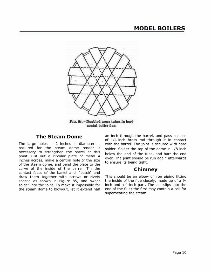
and doubled (see Figure 84), or even trebled,the heating surface may be increased to 180-200 square inches. With a powerful blow-lampthis boiler raises a lot of steam.
Tubing the Furnace Flue
Before any of the holes are made, the lines onwhich the centres lie must be scored from endto end of the flue on the outside. The positionsof these lines are quickly found as follows: --Cut out a strip of paper exactly as long as thecircumference of the tube, and plot the centerlines on it. The paper is then applied to thetube again, and poppet marks made with acenter punch opposite to or through the markson the paper. Drive a wire-nail through apiece of square wood and sharpen the point.Lay the flue on a flat surface, apply the end ofthe nail to one of the poppet marks, and drawit along the flue, which must be held quitefirmly. When all the lines have been scored,the centering of the water tubes is a very easymatter.
The two holes for any one tube should bebored independently, with a drill somewhatsmaller than the tube, and be opened to agood fit with a reamer or broach passedthrough both holes to ensure their sides beingin line. Taper the tubes -- 2-7/8 inches longeach -- slightly at one end, and make one ofthe holes a bit smaller than the other. Thetapered end is passed first through the largerhole and driven home in the other, but not soviolently as to distort the flue. If the tubes aremade fast in this way, the subsequent silver-soldering will be all the easier.
Page 7

MODEL BOILERS
Page 8

MODEL BOILERS
Page 9
MODEL BOILERS
The Steam DomeThe large holes -- 2 inches in diameter --required for the steam dome render itnecessary to strengthen the barrel at thispoint. Cut out a circular plate of metal 4inches across, make a central hole of the sizeof the steam dome, and bend the plate to thecurve of the inside of the barrel. Tin thecontact faces of the barrel and "patch" anddraw them together with screws or rivetsspaced as shown in Figure 85, and sweatsolder into the joint. To make it impossible forthe steam dome to blowout, let it extend half
an inch through the barrel, and pass a pieceof 1/4-inch brass rod through it in contactwith the barrel. The joint is secured with hardsolder. Solder the top of the dome in 1/8 inchbelow the end of the tube, and burr the endover. The joint should be run again afterwardsto ensure its being tight.
ChimneyThis should be an elbow of iron piping fittingthe inside of the flue closely, made up of a 9-inch and a 4-inch part. The last slips into theend of the flue; the first may contain a coil forsuperheating the steam.
Page 10

MODEL BOILERS
A Multi-Tube BoilerFigs. 86 and 87 are respectively end and sideelevations of a multi-tube boiler having over600 square inches of heating surface -- mostof it contributed by the tubes -- and intendedfor firing with solid fuel.
The boiler has a main water-drum, A, 5 inchesin diameter and 18 inches long, and twosmaller water-drums, B and C, 2-1/2 by 18inches, connected by two series of tubes, Gand H, each set comprising 20 tubes. The Htubes are not exposed to the fire so directly asthe G tubes, but as they enter the main drumat a higher point, the circulation is improvedby uniting A to B and C at both ends by large
1-inch drawn tubes, F. In addition, B and Care connected by three 3/4-inch cross tubes,E, which prevent the small drums spreading,and further equalize the water supply. A 1-1/2-inch drum, D, is placed on the top of A tocollect the steam at a good distance from thewater.
Materials
In addition to 1-1/2 feet of 5 by 3/32 inchsolid-drawn tubing for the main, and 3 feet of2-1/2 by 1/16 inch tubing for the lowerdrums, the boiler proper requires 22-1/2 feetof 1/2-inch tubing, 19 inches of 3/4-inchtubing, 2-1/4 feet of 1-inch tubing, 1 foot of1-1/2-inch tubing, and ends of suitable sizefor the four drums.
Page 11

MODEL BOILERS
Page 12

MODEL BOILERS
Page 13

MODEL BOILERS
CONSTRUCTIONThe centres for the water-tubes, G and H,should be laid out, in accordance with Figure88, on the tops of B and C and the lower partof A, along lines scribed in the mannerexplained on p. 207. Tubes H must be bent toa template to get them all of the same shapeand length, and all the tubes be preparedbefore any are put in place. If the tubes areset 7/8 inch apart, center to center, instead of1-1/4 inches, the heating surface will begreatly increased and the furnace casingbetter protected.
Assembling
When all necessary holes have been madeand are of the correct size, begin by rivetingand silver-soldering in the ends of the drums.Next fix the cross tubes, E, taking care thatthey and B and C form rectangles. Then slipthe F, G, and H tubes half an inch into the
main drum, and support A, by means of stripspassed between the G and H tubes, in itscorrect position relatively to B and C. The Etubes can now be pushed into B and C andsilver-soldered. The supports may then beremoved, and the a and H tubes be got intoposition and secured. Drum D then demandsattention. The connecting tubes, KK, shouldbe silver-soldered in, as the boiler, if properlymade, can be worked at pressures up to 100lbs. per square inch.
The casing is of 1/20-inch sheet iron, and infive parts. The back end must be holed toallow A, B, and C to project 1 inch, and have afurnace-door opening, and an airway at thebottom, 5 inches wide and 1 inch deep, cut init. The airway may be provided with a flap, toassist in damping down the fire if too muchsteam is being raised. In the front end makean inspection opening to facilitate cleaning thetubes and removing cinders, etc.
Page 14

MODEL BOILERS
The side plates, m m, are bent as shown inFigure 86, and bolted to a semicircular topplate, n, bent to a radius of 6 inches. A slot,1-1/2 inches wide and 11-1/2 inches long,must be cut in the top, n, to allow it to bepassed over drum D; and there must also be a3 or 3-1/2 inch hole for the chimney. A plate,p, covers in D. A little plate, o, is slipped overthe slot in n, and asbestos is packed in allround D. The interior of the end, side, and thetop plates should be lined with sheet asbestosheld on by large tin washers and screw bolts.To protect the asbestos, movable iron sheetsmay be interposed on the furnace side. Theseare replaced easily if burnt away. The piecesm m are bent out at the bottom, and screweddown to a base-plate extending the wholelength of the boiler.The fire-bars fill the rectangle formed by thetubes B, El, and E2. A plate extends from thetop of E2 to the front plate of the casing, toprevent the furnace draft being "short
circuited."
Boiler FittingsSafety Valves
The best all-round type is that shown inFigure 89. There is no danger of the settingbeing accidentally altered, as is very possiblewith a lever and sliding weight. The valveshould be set by the steam gage. Screw itdown, and raise steam to the point at whichyou wish the safety valve to act, and thenslacken off the regulating nuts until steamissues freely. The lock nuts under the cross-bar should then be tightened up. In the caseof a boiler with a large heating surface, whichmakes steam quickly, it is important that thesafety-valve should be large enough to masterthe steam. If the valve is too small, thepressure may rise to a dangerous height, evenwith the steam coming out as fast as thevalve can pass it.
Page 15
MODEL BOILERS
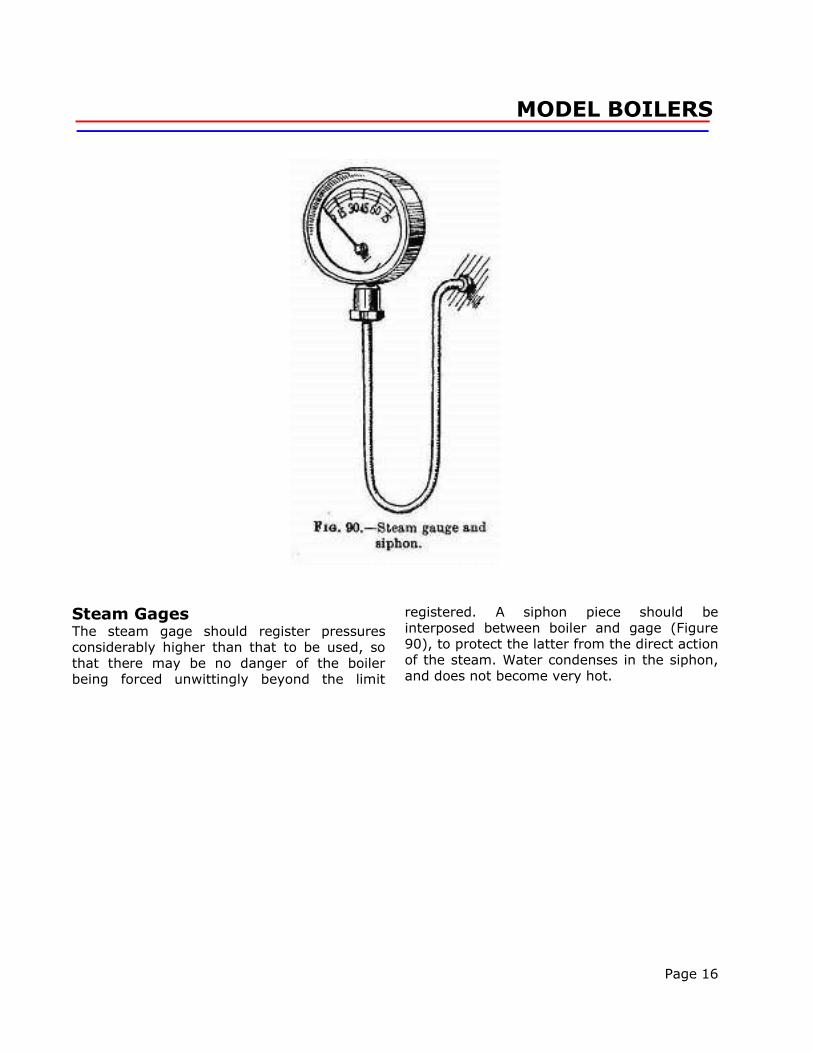
Steam GagesThe steam gage should register pressuresconsiderably higher than that to be used, sothat there may be no danger of the boilerbeing forced unwittingly beyond the limit
registered. A siphon piece should beinterposed between boiler and gage (Figure90), to protect the latter from the direct actionof the steam. Water condenses in the siphon,and does not become very hot.
Page 16

MODEL BOILERS
Water Level Gages...... should have three taps (Figure 91), twobetween glass and boiler, to cut off the waterif the glass should burst, and one for blowingoff through. Very small gages are a mistake,as the water jumps about in a small tube.When fitting a gage, put packings between the
bushes and the glass-holders, substitute apiece of metal rod for the glass tube, and packthe rod tightly. If the bushes are now sweatedinto the boiler end while thus directed, thegage must be in line for the glass. Thismethod is advisable in all cases, and isnecessary if the boiler end is not perfectly flat.
Page 17

MODEL BOILERS
Pumps
Where a pump is used, the supply shouldenter the boiler below low-water level througha non-return valve fitted with a tap, so thatwater can be prevented from blowing backthrough the pump.
Filling Caps
The filling cap should be large enough to takethe nozzle of a good-sized funnel with someroom to spare. Beat the nozzle out of shape,to give room for the escape of the air dis-placed by the water.
The best form of filling cap has a self-seatingground plug, which, if properly made, issteam-tight without any packing. If needed,asbestos packing can easily be insertedbetween plug and cap.
Mud-holes
All but the smallest boilers should have amud-hole and plug in the bottom at a pointnot directly exposed to the furnace. In Figure
82 it is situated at the bottom of the barrel. InFigs. 86 and 87 there should be a mud-hole inone end of each of the three drums, A, B, andC. The plug may be bored at the center for ablow-off cock, through which the boiler shouldbe emptied after use, while steam is up, andafter the fire has been "drawn." Emptying inthis way is much quicker than when there isno pressure, and it assists to keep the boilerfree from sediment.
Steam Cocks
The screw-down type (Figure 92) is verypreferable to the "plug" type, which is apt toleak and stick.
Testing Boilers
The tightness of the joints of a boiler is besttested in the first instance by means ofcompressed air. Solder on an all-metal cyclevalve, "inflate" the boiler to a considerablepressure, and submerge it in a tub of water.The slightest leak will be betrayed by a stringof bubbles coming
Page 18

MODEL BOILERS
directly from the point of leakage. Mark anyleaks by plain scratches, solder them up, andtest again.
The boiler should then be quite filled with coldwater, and heated gradually until the pressuregage has risen to over the working pressure.There is no risk of an explosion, as the volumeof the water is increased but slightly.
The third test is the most important and mostrisky of all-namely, that conducted understeam to a pressure well above the workingpressure.
In order to carry out the test without risk, oneneeds to be able to watch the steam-gagefrom a considerable distance, and to have thefire under control. My own method is to setthe boiler out in the open, screw down thesafety-valve so that it cannot lift, and raisesteam with the help of a blow-lamp, to whicha string is attached wherewith to pull itbackwards along a board. If the boiler is to be
worked at 50 lbs., I watch the steam gagethrough a telescope until 100 lbs. is recorded,then draw the lamp away. After passing thetest, the boiler, when pressure has fallen, say,20 lbs., may safely be inspected at closequarters for leaks.
This test is the only quite satisfactory one, asit includes the influence of high temperature,which has effects on the metal not shown by"cold" tests, such as the hydraulic.
Do not increase your working pressurewithout first re-testing the boiler to double thenew pressure to be used.
Fuels
For very small stationary boilers themethylated spirit lamp is best suited, as it issmell-less, and safe if the reservoir be keptwell apart from the burner and the supply iscontrollable by a tap or valve. (See Figure104.)
Page 19

MODEL BOILERS
For medium-sized model boilers, and for smalllaunch boilers, benzoline or petrol blow-lampsand paraffin stoves have become verypopular, as they do away with stoking, andthe amount of heat is easily regulated bygoverning the fuel supply. Figure 94 is asketch of a blow-lamp suitable for thehorizontal boiler, while Figure 95 shows aconvenient form of paraffin stove with silent"Primus" burner, which may be used for ahorizontal with considerable furnace space orfor vertical boilers. In the case of all theseliquid fuel consumers, the amount of heatdeveloped can be increased by augmentingthe number of burners. Where a gas supply isavailable its use is to be recommended forsmall stationary boilers.
Solid Fuels
The chief disadvantages attaching to these aresmoke and fumes; but as a solid fuel givesbetter results than liquid in a large furnace, itis preferred under certain conditions, one ofthem being that steam is not raised in a livingroom. Charcoal, coke, anthracite coal, andordinary coal partly burned are the fuels touse, the fire being started with a liberal supplyof embers from an open fire. Every solid-fuelboiler should have a steam-blower in thechimney for drawing up the fire; and if areally fierce blaze is aimed at, the exhaustfrom the engine should be utilized for thesame purpose.
From The Project Gutenberg EBook of Things To Make, by Archibald Williams
This eBook is for the use of anyone anywhere at no cost and with almost no restrictions whatsoever. You may copy it, give it away or re-use it under the terms of the Project Gutenberg License included with this eBook
or on line at www.gutenberg.net
Transcribed by David Lee ([email protected]) and Ben Conway ([email protected])
Created using OpenOffice and Adobe Photo Delux
Page 20