model c - kegel | lane maintenance solutions | kegel.net
TRANSCRIPT

Table of Contents - 1 of 2
TABLE OF CONTENTS – MODEL C
SECTION I - INTRODUCTION ................................................................................................................. 1
A. OVERVIEW .............................................................................................................................................. 1
B. MACHINE SPECIFICATIONS ...................................................................................................................... 1
C. CARE AND SAFETY PROCEDURES ............................................................................................................ 2
D. THEORY OF OPERATION .......................................................................................................................... 3
SECTION II - MACHINE DESCRIPTION ............................................................................................... 1
A. REAR; CENTER; FRONT; RIGHT; & LEFT SIDE ......................................................................................... 1
B. KEYPAD .................................................................................................................................................. 2
C. CONDITIONING (REAR) END COMPONENTS ............................................................................................. 3
D. CENTER COMPARTMENT COMPONENTS .................................................................................................. 5
E. CLEANING (FRONT) END COMPONENTS ................................................................................................ 12
F. BOTTOM SIDE COMPONENTS ................................................................................................................. 14
G. RIGHT SIDE COMPONENTS .................................................................................................................... 15
H. LEFT SIDE COMPONENTS ...................................................................................................................... 16
SECTION III - PRE-INSTALLATION ...................................................................................................... 1
SECTION IV - OPERATING INSTRUCTIONS ....................................................................................... 1
A. FILLING THE CONDITIONER TANK ........................................................................................................... 1
B. FILLING OF CLEANER SUPPLY TANK ....................................................................................................... 2
C. TURNING THE UNIT ON ........................................................................................................................... 3
D. KEYPAD DISPLAY ................................................................................................................................... 4
E. OPERATORS MENU SELECTIONS.............................................................................................................. 5
1. Run Mode........................................................................................................................................... 5
2. Return to Foul Line Menu ................................................................................................................. 6
3. Change Program Settings .................................................................................................................. 6
4. System Control Cleaning ................................................................................................................. 20
5. System Control Duster Menus ......................................................................................................... 23
6. Auto Program .................................................................................................................................. 25
7. Test Output ...................................................................................................................................... 27
8. Pump Output Volume Test ............................................................................................................... 28
9. Copyright ......................................................................................................................................... 30
SECTION V - ADJUSTMENTS .................................................................................................................. 1
A. CLEANING CLOTH REPLACEMENT & ADJUSTMENT ................................................................................. 1
B. FILLING OF CLEANER SUPPLY TANK ....................................................................................................... 3
C. EMPTYING OF RECOVERY TANK ............................................................................................................. 3
D. ADJUSTMENT OF SPRAY JETS .................................................................................................................. 4
E. GUIDE ROLLER ADJUSTMENTS ................................................................................................................ 5
F. SQUEEGEE ASSEMBLY ADJUSTMENT ....................................................................................................... 6
G. BUFFER BRUSH ADJUSTMENT ................................................................................................................. 7
H. TRANSFER ROLLER ADJUSTMENT ........................................................................................................... 9
I. END CLEANING DISTANCE TRAVEL ADJUSTMENT .................................................................................... 9
J. OIL HEAD TIMING ADJUSTMENT ............................................................................................................ 11
K. DRIVE MOTOR SPEED ADJUSTMENTS: .................................................................................................. 13

Table of Contents - 2 of 2
SECTION VI - MAINTENANCE ............................................................................................................... 1
A. POWER CORD ......................................................................................................................................... 1
B. SQUEEGEE .............................................................................................................................................. 2
C. LANE-TO-LANE CASTERS ....................................................................................................................... 2
D. DRIVE WHEELS ...................................................................................................................................... 2
E. VACUUM MOTOR ................................................................................................................................... 2
F. INSIDE MACHINE ..................................................................................................................................... 2
G. RECOVERY TANK REMOVAL .................................................................................................................. 2
H. FILTERS .................................................................................................................................................. 3
I. CHANGING OF CONDITIONER ................................................................................................................... 3
J. BUFFING BRUSH ...................................................................................................................................... 6
K. PATTERN SMOOTHING PADS ................................................................................................................... 6
SECTION VII - INPUTS AND OUTPUTS ................................................................................................ 1
A. INPUTS ................................................................................................................................................... 1
B. OUTPUTS ................................................................................................................................................ 2
C. DESCRIPTION OF INPUTS ......................................................................................................................... 3
SECTION VIII - OIL PATTERNS ............................................................................................................. 1
A. UNDERSTANDING THE MACHINE ............................................................................................................ 1
B. PROVING THE OIL PATTERN.................................................................................................................... 6
C. BOARD CHART FOR CALCULATING PROGRAM LOADS .......................................................................... 10
SECTION IX - PROGRAM DESCRIPTIONS ......................................................................................... 1
A. OFFENSE SAMPLE PATTERN SETTINGS ................................................................................................... 3
B. CONTROL SAMPLE PATTERN SETTINGS ................................................................................................... 4
SECTION X - APPENDIX ........................................................................................................................... 1
A. RECOMMENDED MAINTENANCE INSPECTIONS ....................................................................................... 1
RECOMMENDED PART REPLACEMENT SCHEDULE……….……….…………………………………….6
B. INSTRUCTIONS TO CLEAN WATER SPRAY PUMP ................................................................................... 7
C. PROCEDURE FOR CLEANING OIL CONTROL VALVES .............................................................................. 9
D. OPERATORS MENU SELECTIONS .......................................................................................................... 12
E. TROUBLESHOOTING OUTPUTS AND INPUTS .......................................................................................... 14
1. Outputs ............................................................................................................................................ 14
2. Inputs ............................................................................................................................................... 15
F. MACHINE ERROR MESSAGES ............................................................................................................... 16
G. TECHNICAL SUPPORT INSTRUCTIONS................................................................................................... 22
H. PRESSURE REGULATOR TUBING CHART .............................................................................................. 24
SECTION XI - MECHANICAL DRAWINGS........................................................................................... 1
A. ATTACHING PARTS ................................................................................................................................1
B. PARTS LIST ............................................................................................................................................1

Operators Manual
Section 1-1
SECTION I - Introduction
A. Overview
This lane cleaning and conditioning machine represents
advanced technology in automated lane care. Clean and
consistent bowling conditions are accomplished through the
use of an on-board keypad linked to a programmable logic
controller.
A patented conditioner metering transfer system, vacuum
cleaning and squeegee system, and duster system allow the
machine to maintain clean and consistent bowling conditions.
In addition to this manual, Kegel has developed an On-
line Support Interface called KOSI. This software provides
additional functions that are otherwise not available to the
operator. KOSI should be used as a supplement to this
manual.
IT IS VERY IMPORTANT THAT THE OPERATOR THOROUGHLY READ AND
UNDERSTAND THIS OPERATING MANUAL BEFORE USING THE MACHINE.
WHEN ALL ELSE FAILS...READ THE MANUAL OR WATCH KOSI.
Should you have any questions regarding any procedures
pertaining to the proper operation of this machine, please
contact Kegel at (863) 734-0200 also via [email protected] or Brunswick at (231) 725-4966 also via [email protected].
B. Machine Specifications
Models: 61860329110 / 17-4700 Kustodian (115V/60Hz) Model C
61860329220 / 17-470050 Kustodian (230V/50Hz) Model C
Power Supply: Class I – Single Phase
110-120 Volts, 60 Cycle, 15 Amps
220-230 Volts, 50 Cycle, 12 Amps
Dimensions: Width - 55-1/4" (140.34 cm)
Height – 14-1/2" (36.83 cm)
Length – 40-3/4" (103.51 cm)
Weight - 350 pounds (158.8 kg)

Operators Manual
Section 1-2
C. Care and Safety Procedures
This machine is manufactured of the highest quality
materials, but keep in mind that this is a sensitive piece
of equipment. Care should be taken to see that it is not
dropped, knocked around, or handled roughly.
Doing so may damage the programmable logic controller,
its components, the conditioner transfer system, the duster
assembly, or the vacuum cleaning and squeegee system.
For care and safety reasons, follow these precautions:
• Avoid spilling any liquids or chemicals inside of the
machine.
• Do not operate the machine with an extension cord or
power cord other than the one provided.
• Make sure that the power outlet used provides the correct
voltage and amps. It must be a clean circuit with no
other loads on it.
• Do not attempt to make any wiring modifications.
• Do not attempt to re-program the system software.
• Do not operate the machine in an upright position.
• Always empty the recovery tank before standing the
machine up and transporting it. Failure to empty the
tank will cause the dirty cleaner to either spill out
through the vacuum motor or out of the squeegee when
going over ramps. Then the next time the machine is
started, it will blow cleaner out of the vacuum exhaust.
Not following the above recommendations may cause
damage to the machine, its computer, persons operating it,
or void the warranty.
An authorized factory-trained Distributor should train
persons assigned the responsibility of operating this
equipment how to properly use it.

Operators Manual
Section 1-3
D. Theory of Operation
This machine uses proven "SANCTION TECHNOLOGY"
patented by Kegel. This technology is the precise metering
of oil to each board by volume. This model has the benefits
of years of research and development, making SANCTION
TECHNOLOGY available for any bowling center trying to gain
control over the oil pattern.
The machine uses one Fluid Metering Pump. The piston
and cylinder are made of ceramic, milled to almost perfect
clearances. The pump has no valves to impair its operation.
The piston revolves as well as reciprocates during
operation.
With the pump rotating at a constant RPM the oil is
pumped at an exact flow rate to a three-way valve known as
the Oil Pattern Control Valve. The valve in its OFF state
routes the oil back to the oil tank. When turned ON the
valve routes the oil to a line connected to the Oil Head.
The OIL HEAD travels back and forth across the transfer
system at a constant speed, much like the printer head on a
computer printer. The Oil Pattern Control Valve is then
turned ON and OFF according to the chosen program. The
result is a series of board to board streams of oil applied
to the transfer system as the machine travels down the lane.
This stream of oil is a consistent, adjustable, and
measurable amount per board. An example of a common league
condition in the U.S. might be three 2 board to 2 board
streams, followed by two 9 to 9’s, two 10 to 10’s, and four
11 to 11’s as the machine travels down the lane.

Operators Manual
Section 1-4
The total volume amount per board of the pattern can be
represented by an exact amount.
This is done by simply multiplying:
1) the amount of oil per board value (determined during calibration)
by
2) the number of times the stream crossed each board.
Although it is not information that will be used daily,
it is a way of explaining a lane condition in exact terms.
These measurements can be written down and duplicated in the
future.
In other words, it defines a lane condition so that it
can be recognized and explained to anyone, much like any
other specification of the bowling lane such as the length
and width.
Anyone who uses this machine and pays attention,
will begin to understand lane conditions like never before.
Because all adjustments to the oil pattern
are exact and repeatable,
Sanction Technology is an instrument,
not just a lane machine.

Operators Manual
Section 2-1
SECTION II - Machine Description
A. Rear; Center; Front; Right; & Left Side
With the machine setting on the approach in a position
ready to be operated on the first lane, the following
descriptions will be used:
• CONDITIONING (REAR) END: The CONDITIONING or REAR END shall be the end of the machine closest to the operator
and nearest the approach, where the buffing brush is
located.
• CENTER COMPARTMENT: The COMPUTER or CENTER COMPARTMENT houses the electrical components and is located between
the CONDITIONING END and the CLEANING END. Three
partitions make up the compartment:
• the vacuum and transfer motor section (on the right);
• the buffer motor section (on the left side) and;
• the computer and drive motor section (in the center).
• CLEANING (FRONT) END: The CLEANING or FRONT END shall be the end nearest to the pins, where the recovery tank and
the Duster Assembly are located.
• RIGHT SIDE: The RIGHT SIDE is the side to the right of the operator as he faces the pins. This is also the ten-
pin side.
• LEFT SIDE: The LEFT SIDE is the side opposite the right, to the left of the operator as he faces the pins (seven-
pin side).

Operators Manual
Section 2-2
B. Keypad
Located under the lid of the conditioning end is the
computer keypad. This keypad is used to enter all
programming information. The keypad consists of 6 input
keys, two indicator lights and a two-line Liquid Crystal
Display (LCD) where the menu items and prompts appear.
• INDICATOR LIGHTS: The red indicator light comes on any time you press any of the 6 keys. The green indicates
when the NEXT key is enabled in the Change Program area.
The green light will also come on after the Managers
Password has been entered correctly.
• MENU/F1: Pressing this key will display and advance the available main menus for the operator. It will also act
as a zero button when the machine is in operation. When
the key is pressed the machine will stop, the program
will zero, and the menu will advance to MANUAL REVERSE.
• NEXT/F2: Use this key to advance within a main menu from one menu prompt to the next. It is also used to advance
the output number in the Test Output menu.
• DOWN ARROW/F3: Use of this key will decrement or decrease numbers needed in certain menu prompts. Holding the key
down will make the numbers decrease faster.
The Down Arrow will not work in screens that display a
menu prompt requesting you to choose a program number.
• UP ARROW/F4: Use of this key will increment or increase numbers needed in certain menu prompts. Holding the key
down will make the numbers increase faster. The Up Arrow
will loop around to 01 when the upper limit is exceeded.
The Up Arrow is also a backup start button.
• ENTER/F5: This key is used in the Change Program menu for entering data in the oil load screens. The key is also
used to turn outputs ON and OFF in the Test Output menu.
• RESET/F6: This key has four functions.
� It zeros the program like the Menu key, but it does not advance to the next menu,
� it is used to start the Volume Test, � it resets the Duster Cloth counters, and � it is used to return back to the Start Screen from
any menu prompt (except for the two situations
mentioned above).
NOTE: The Managers Password can be any combination of F3, F4, and F5. Contact Tech Support to change the password.

Operators Manual
Section 2-3
C. Conditioning (Rear) End Components
Located on the conditioning end of the machine are the
following components:
• DISTANCE WHEELS: Located on the inside rear wall of the conditioning end are the lane distance wheels. These
wheels measure the distance the machine travels down the
lane in increments of one inch. This is done by counts
stored in the PLC from the proximity sensor or Lane
Distance Sensor (LDS) mounted on the center pillow block.
• BUFFER BRUSH: Located near the rear wall of the conditioning end is the buffer brush assembly. The belt-
driven brush removes conditioner from the transfer roller
and places it onto the lane surface.
• BRUSH LIFT CAM: Located to the left of the cleaner pump on the side plate is the brush lifting cam and switches.
• CONDITIONER COMPONENTS: Located under the splash guard on the rear wall are the following conditioning components:
� the oil pump and motor;
� the pulse dampener tubing (to smooth oil streams);
� the valve assembly (24VDC) to control oil flow;
� the pressure gauge (keep pressure at 10-15 PSI);
� the pressure regulating capillary tube;
� the oil tank and filter (capacity is 0.63 gallons or
2400 milliliters);
� a vent valve to prevent vacuum in oil tank;
� a capacitor for the oil pump motor;
� and a terminal block assembly.
• SUPPLY TANK: Mounted left of center on the rear wall is the cleaner supply tank. The capacity of this tank is
approximately 1-7/8 gallons (7.1 liters); enough volume
to completely clean in excess of 20 lanes. A vent valve
prevents a vacuum inside the tank during operation.

Operators Manual
Section 2-4
• PUMP MOTOR: Mounted on the rear wall to the left of the cleaner tank is the cleaner pump motor. This motor pumps
the cleaning liquid from the supply tank through the
spray jets and onto the lane surface. Check fittings
periodically for leaks to prevent potential moisture
damage.
• OIL HEAD: Located above the transfer roller is the Moving Head. This head rides along a guide bar and applies the
conditioner to the transfer roller. The tip can be
removed when performing a calibration check. A collar
retains the tip height adjustment and locks the tip into
the spring-loaded oil head.
• TRANSFER ROLLER: Mounted below the moving head is the conditioner transfer roller. This stainless steel roller
is chain driven and transfers conditioner onto the
buffing brush.
• PATTERN SMOOTHING ASSEMBLY: Mounted in front of the transfer roller are 10 spring-loaded pads that touch the
transfer roller. These pads help distribute the
conditioner around the roller as it rotates.
• HEAD PROXIMITY SENSORS: Located at each end of the head mounting bar is a proximity sensor. These sensors feed
information to the PLC to reverse the conditioning head.
These sensors are also used to "time" the oil position
sensors.
• START/INTERLOCK/RESUME BUTTON: Located on the handle is the Start/Interlock/Resume button. This button is used
to START the machine; STOP it any time during the
conditioning run; or to RESUME operation after it has
stopped for an error message or some other reason.

Operators Manual
Section 2-5
D. Center Compartment Components
The Center Compartment of the machine is divided into
three sections. From left to right, they are the buffer
motor section, the computer control and drive motor section,
and the vacuum and transfer motor section.
The following components are found in the LEFT section
of the center compartment:
• BUFFER MOTOR: Mounted on the left side plate is the buffer brush motor. This AC single-speed motor rotates
the buffer brush on the lane.
• TERMINAL BLOCK: Mounted on the left side plate above the buffer motor is a set of terminal blocks. These junction
blocks are used for the left proximity switch and the
tach sensor. The following components are found in the MIDDLE
section of the center compartment:
• CONTROL PLATE ASSEMBLY: The control plate assembly can be removed from the machine for maintenance by unplugging
the wire connectors and removing four screws. Located on
top of the control plate are the following components:
� Buffer Motor Contactor (CR12); � Programmable Logic Controller; � CR1 Forward Relay (LY4); � CR2 Reverse Relay (LY3); � CR3 Cleaner Pump Relay (LY2); � CR4 to CR10 PLC Secondary Relays; � CR11 Vacuum Motor Relay (LY2); � Operation Toggle Switch; � Speed Adjustment Trimpots; � Circuit Breaker; � Fuses.
Located on bottom of the control plate are the
following components:
� Printed Circuit Board; � Terminal Block Assembly.

Operators Manual
Section 2-6
• BUFFER MOTOR CONTACTOR: Mounted on the top left corner is the buffer motor contactor (designated as CR12). This
component conducts AC power to the buffer motor when the
PLC relay engages the coil. A din rail secures the
contactor to the plate.
• PROGRAMMABLE LOGIC CONTROLLER (PLC): The PLC or PC is also mounted on the din rail. The terminal strips are
removable if a replacement is necessary. Use care to
prevent damage to the PLC, it controls all the functions
of the lane machine.
WARNING: The PLC contains a Lithium battery. When it is replaced, the old battery should be discarded in
accordance with local regulations.
• CONTROL RELAY 1: This relay controls the forward operation of the drive motor. It is an LY4 type relay.
• CONTROL RELAY 2: This relay controls the reverse operation of the drive motor. It is an LY3 type relay.
• BRAKE RESISTOR: Mounted to CR#1 and CR#2 is the Brake Resistor. This resistor stops the drive motor when the
drive motor relays are turned off.
• CONTROL RELAY 3: This relay controls the operation of the cleaner pump motor. It is an LY2 type relay with a
115VAC or 230VAC coil.
• PLC RELAYS: Seven of the output relays of the PLC (located on OUTPUT CH11) are protected by a bank of small
secondary relays. These 24VDC relays should prevent
damage to the PLC if a short-circuit occurs. A light on
top of the relay indicates when the coil is energized.
These relays are easily replaceable, if necessary.

Operators Manual
Section 2-7
The following outputs are protected by a 24VDC secondary
relay:
CR OUTPUT DESCRIPTION
4 11CH 00 OIL HEAD MOTOR (LEFT TO RIGHT)
5 11CH 01 OIL HEAD MOTOR (RIGHT TO LEFT)
6 11CH 02 BRUSH LIFTING MOTOR
7 11CH 03 SQUEEGEE MOTOR
8 11CH 04 DUSTER UNWIND MOTOR
9 11CH 05 DUSTER WINDUP MOTOR
10 11CH 06 CONDITIONER PUMP MOTOR
• CONTROL RELAY 11: This relay controls the operation of the vacuum motor. It is an LY2 type relay with a 24VDC
coil.
• OPERATION TOGGLE SWITCH: This switch controls whether the program will CLEAN only, CONDITION only, or CLEAN and
CONDITION at the same time. The machine will not
calibrate the Pump Output if switch is set to CLEAN ONLY.
• DRIVE MOTOR SPEED RELAYS AND ADJUSTING POTS: The speed adjusting pots are accessed through the top of the
control plate. The relays and trimpots are mounted to
the bottom side. Low speed comes on when either the
forward or the reverse LY-type relay is on. The small
speed relays are used for the other five speeds. The
trimpots regulate each of the 6 speeds of the drive
motor.
Always adjust the speeds from low to high speed (left to
right). Use the Range Pot only if necessary to give all
trimpots some additional adjustment.
The trimpots, and their inches per second speed ranges,
go in order from left to right as follows:
9-10 IPS (Affects speed for all other trimpots).
13-14 IPS
17-18 IPS
21-22 IPS
25-26 IPS
29-30 IPS
RANGE Pot (Adjusts speed for all trimpots).

Operators Manual
Section 2-8
NOTE: Speed trimpot 1 will also affect the other speeds. Always adjust Speed 1 first, and if a change is made to the
Range Pot, begin adjusting again from Speed 1.
• PROTECTIVE DEVICES: Mounted on the PLC plate are several fuses and one circuit breaker. These components protect
the operator and machine in the event of a current
overload. The following is a list, from left to right,
of the components:
� Main Circuit Breaker: The circuits for the entire machine are protected with a circuit breaker. It is
rated at 15A on a 115V model, and at 10A on a 230V
model.
� PLC Power Fuse: The PLC power supply is protected by a single slow blow fuse. It is rated at 0.5A on a
115V model, and 500mA on a 230V model.
� PLC Common Fuse: The PLC Outputs are protected by a single slow blow fuse. It is rated at 0.5A on a
115V model, and 500mA on a 230V model.
� Drive Motor Fuse: The drive motor control board is protected by 2 slow blow fuses, one for L1 and one
for L2. These are ceramic-type fuses rated at 4A.
� Transfer Roller Motor Fuse: The transfer roller motor is protected with a slow blow fuse. It is
rated at 2.25A on a 115V model, and at 1A on a 230V
model.
� Conditioner Pump Motor Fuse: The oil pump motor is protected with a slow blow fuse. It is rated at
0.75A on a 115V model, and at 315mA on a 230V model.
� Cleaner Pump Fuse: The cleaner pump is protected with a slow blow fuse. It is rated at 0.75A on a
115V model, and at 315mA on a 230V model.
� Secondary Relay Common: The PLC secondary relays are protected by a 4A fuse on both 115V and 230V models.

Operators Manual
Section 2-9
� Vacuum Fuse/Circuit Breaker: The vacuum motor is protected with a slow blow fuse or a circuit
breaker. The 115V model uses a ceramic-type fuse
rated at 10A; or a circuit breaker rated at 8A is
used on a 230V model.
Other protective measures include the following:
� PLC Program: The program also acts as a protective device on certain motors. These motors "time out"
or have built in monitoring that trips an error
message and stops operation. This will prevent the
motors from overheating in the event of a locked
rotor condition. The following motors are protected
with the PLC Program: DC Drive Motor; Brush Lifting
Motor; Squeegee Motor; Oil Head Motor; and the
Duster Unwind and Wind-Up Motors.
� Buffer Motor: A fuse is not required for the AC motor, it has an automatic thermal overload breaker.
A button must be pressed on the back of the AC motor
to reset the overload trip circuit.
WARNING: Make sure no power is applied to the machine when re-setting the overload breaker (so the
motor won't start unexpectedly).

Operators Manual
Section 2-10
The following components are found underneath the
control plate in the center compartment:
• DRIVE MOTOR PRINTED CIRCUIT BOARD: Mounted on the bottom side of the control plate is a printed circuit board with
relays and trimpots. This board controls the DC voltage
to regulate the drive motor speeds.
• TERMINAL BLOCK ASSEMBLY: Mounted on the bottom of the control plate are the main terminal blocks for the
machine. The plate lifts out of the machine by removing
the four mounting screws to allow access to this wiring
when trouble-shooting a problem.
• DRIVE MOTOR: Mounted under the control plate is the DC drive motor. It turns the drive shaft and the tachometer
actuating disk. This motor is mounted on slots to allow
the chain tension to be adjusted.
• DRIVE MOTOR SPEED CONTROL BOARD: Mounted to back wall of the middle compartment, under the control plate, is the
drive motor speed control board. The board converts AC
voltage into DC voltage for the drive motor. Do not
adjust the trimpots on the board unless instructed to do
so by the Kegel Technical Support staff.
• EMI FILTER: (On 230 Volt Machines Only) Mounted directly below the drive motor speed control board is an EMI
filter. The speed control board must be filtered to
reduce line conducted and radiated emissions. This
filter must be connected properly to ensure compliance
with Electromagnetic Compatibility Directives (CE Mark).
• EMI FILTER: (On 230 Volt Machines Only) Mounted below the relay plate is a large EMI filter. The electrical
circuits of the entire machine are filtered to reduce
line conducted and radiated emissions. This filter must
be connected properly to ensure compliance with
Electromagnetic Compatibility Directives (CE Mark).
• EMI FERRITE: (On 230 Volt Machines Only) The 24V DC circuit is filtered at the output of the PLC Power
Supply. A ferrite is clamped to the Brown and Yellow
wires to reduce line conducted emissions. This component
is required to comply with CE Directives.

Operators Manual
Section 2-11
The following components are found in the RIGHT section
of the center compartment:
• VACUUM MOTOR: Located on the right side is the vacuum motor. This motor is used with the squeegee assembly and
recovery tank to vacuum the cleaner off the lane. A
specially designed chamber reduces the noise created by
the vacuum. This motor needs regular maintenance, and is mounted by two 1/4-20 bolts for easy access.
NOTE: The lid can be taken off the machine to make it easier to remove the vacuum motor and perform necessary
maintenance.
• TRANSFER ROLLER DRIVE MOTOR: Mounted under the vacuum motor, on the right side plate, is the transfer roller
drive motor. This motor drives the transfer roller
during conditioning runs.
• EMERGENCY STOP BUTTON: (On 230 Volt Machines Only) Located in the right compartment is an emergency stop
switch. This safety button will disconnect power to the
drive components of the machine if there is an emergency.
This button will have to be rotated to be reset and the
start button will need to be pushed to resume operation.
If power is applied to the machine, but the circuits are
dead, check the position of this kill switch.

Operators Manual
Section 2-12
E. Cleaning (Front) End Components
The following components are located under the lid on
the cleaning end of the machine:
• POWER CORD INLET: Mounted on the left side wall is the power cord inlet. This inlet is grounded to the machine
frame. Make sure to use the correct voltage and amperage
when connecting the cord to the inlet.
HIGH VOLTAGE WARNING: Use caution with electrical components. Refer servicing to
qualified personnel. Observe and follow all
Warning and Safety Labels.
• DUSTER UP SWITCH: Located on each side wall is a microswitch. These switches, when actuated, tell the PLC
that the cushion roller is in the UP position. Avoid
getting liquid near these switches (and all electrical
components).
• DUSTER/CLEANING CLOTH ASSEMBLY: Mounted inside and across the entire front end is the Duster Cleaning Cloth
Assembly. Two motors, one located on each side, move the
cloth from one core to the next. The gear motor on the
left side is called the UNWIND MOTOR. When operated, it will let out new cloth from the supply roll. The gear
motor on the right side is the WIND-UP MOTOR. When operated, it will wind up the used, dirty cloth on the
white PVC take-up roller.
The duster uses gravity to clean the lane. The cushion
roller pivots and contacts the lane surface when cloth is
unwound. This makes the cloth contour to the lane
surface for optimum cleaning. At the end of the lane,
just before the end of travel, the duster winds up dirty
cloth and lifts the cushion roller off the lane. The
cloth remains wound up during the return travel to the
foul line.
For best results, use DBA #8460 lane cleaning cloth or
Kegel Kloth (153-0047K) lane cleaning cloth. The machine will use approximately 1-1/2" (3.81 cm) of cloth per
lane.

Operators Manual
Section 2-13
• RECOVERY TANK: The large plastic tank in the center of the compartment is the recovery tank. This tank will
hold over 20 lanes of used liquid without needing to be
emptied. Empty the tank from the inlet side (connected
to squeegee).
Use care when removing tank to prevent spilling liquid in
the machine. Do not drop the tank or handle it roughly.
This may cause it to leak.
• SPRAY JET ASSEMBLIES: Mounted to the front wall are four spray jet assemblies. These assemblies can be angled up
or down, and left or right, to adjust spray coverage to
the entire lane. Mounted with the spray tip is a
combination check valve/filter. The tips in the center
are #8003 and the tips on the outside are #1501. These
provide cleaner coverage across the entire lane.
• VACUUM EXHAUST PLATE: The area where the vacuum exhaust is located is covered with felt in case any moisture
blows through the motor. Use a soft rag to absorb any
moisture that may collect in this area.
• SQUEEGEE CAM & SWITCHES: The position of the squeegee is controlled by two switches mounted on the right side
plate. A cam connected to the squeegee motor has an
offset lobe that actuates the switches. The switch
toward the top of the machine is the Squeegee Down Switch
and the switch located toward the bottom of the machine
is the Squeegee Up Switch. These switches are protected
behind a guard. Prevent moisture from contaminating this
area.
• LIFTING HANDLE: There are two lifting handles mounted on the front panel for lifting and placing the machine on
the approach. When possible, have two people set the
machine down and lift it into the transport position.
• MOMENTARY WHEELS: Mounted on the front outside wall are two small wheels. These wheels come in contact with the
lane momentarily as the machine enters and exits at the
foul line.

Operators Manual
Section 2-14
F. Bottom Side Components
Located on the bottom or underneath the machine are the
following components:
• DRIVE SHAFT: Located toward the center of the bottom is the lane drive shaft. This shaft is driven by the drive
motor.
• DRIVE WHEELS: Mounted on the lane drive shaft are the two drive wheels. These wheels rotate under power from the
drive motor to move the machine on the lane.
• SQUEEGEE ASSEMBLY: Mounted near the front of the machine is the squeegee assembly. This assembly vacuums the
cleaner and oil off of the lane during lane cleaning.
The unique mount for the squeegee allows the tilt or
pitch to be adjusted. There are also independent height
adjustments for the left and right side.
• GUIDE ROLLERS: Mounted on the outside walls are four spring-loaded guide rollers. These tapered rollers ride
along the edge of the lane to keep the machine straight
and square as it travels on the lane surface.
• SKID PLATES: Two small UHMW pieces are mounted to the floor of the machine. These will help prevent damage if
the machine travels too far forward and ends up in the
pit.

Operators Manual
Section 2-15
G. Right Side Components
The following components are located on the right
outside wall of the machine:
• DUSTER WIND-UP MOTOR: Mounted toward the front of the machine is the duster wind-up motor. When this brake
motor operates, it winds-up used cloth and lifts the
cushion roller from the lane surface.
• TRANSPORT HANDLE: A handle is provided to make the machine easier to move while in the transport position.
• LANE-TO-LANE CASTERS: Located on the outside of the frame are two lane to lane casters that support machine as it
is moved on the approach from one lane to the next.
• SQUEEGEE MOTOR: Mounted to the right side plate is the mechanical-brake motor which controls the up and down
movement of the squeegee. A cam is mounted on the shaft
to hold the adjusting linkage for the squeegee pitch.
NOTE: Do not make the pitch linkage too short as this may cause the motor to bind during travel.
• SQUEEGEE ADJUSTMENT: The squeegee height can be adjusted by loosening the pivot mounts located on the side plates
and setting them to the desired height. There is a
separate adjustment for the left and right sides. Make
sure the squeegee stays relatively level in the machine.
• OIL HEAD TIMING PROXIMITY SENSOR: Mounted toward the rear of the machine is a proximity switch that controls the
oiling head. Protected beneath a cover, this proximity
switch keeps track of the position of the oiling head by
sensing an aluminum target. The target is connected to
an idler pulley that controls the belt tension for the
head drive system.
• TRANSFER CHAIN: Mounted beneath a cover is the transfer roller drive chain and sprocket.
• HANDLE CATCH: A small piece of UHMW is mounted to the top of the side wall to hold the handle in place during
transport.

Operators Manual
Section 2-16
H. Left Side Components
The following components are located on the left
outside wall of the machine:
• DUSTER UNWIND MOTOR: Mounted toward the front of the machine is the duster unwind motor. This brake motor
operates to unwind new cloth and lower the cushion roller
onto the lane surface.
• DRIVE TACHOMETER SENSOR: Mounted near the bottom of the left side plate is the DRIVE TACH sensor. A metal target
is rotated as the drive shaft turns. As the target
passes in front of the proximity sensor, pulses are sent
to the PLC. The PLC counts these pulses and calculates
the IPS (INCHES PER SECOND) travel speed of the machine.
This is used to set the 6 different drive speeds of the
machine.
• SQUEEGEE ADJUSTMENT: The squeegee height can be adjusted by loosening the pivot mount and relocating it to the
desired height. There is a separate adjustment for the
left and right sides.
• OIL HEAD DRIVE MOTOR: Located on the outside of the left side panel is the Drive Motor for the Oil Head. This
motor, along with a cogged drive belt, moves the head
back and forth along a rectangular track above the
transfer roller.
• HEAD MOTOR CAPACITOR: Mounted beneath a cover is the capacitor for the oil head motor.
• BUFFER BELT: The buffer belt is located beneath a cover on the left side. It is routed around an idler pulley.
Check the tension of the belt periodically to ensure
proper operation.
• TRANSPORT HANDLE: A handle is provided to make the machine easier to move while in the transport position.
• HANDLE CATCH: A small piece of UHMW is mounted to the top of the side wall to hold the handle in place during
transport.

Operators Manual
Section 2-17
• BUFFER BRUSH LIFT MOTOR: Mounted on the left side of the machine under the handle is the buffer brush lift motor.
This motor lifts the buffer brush off the lane. The
brush needs to be lifted at times where conditioner is
not being applied (i.e. from the end of oil through
pindeck during all cleaning cycles). The brush parks in
the down position. The machine should be stored with the
brush down to prevent the transfer roller from spreading
the fibers too much.
• PRIME PUMP BUTTON: Located next to the handle pivot mount is the cleaner prime pump button. This button will
activate the cleaner pump in any mode of operation. Make
sure the machine is positioned properly before applying
cleaner.
• LANE-TO-LANE CASTERS: Located on the outside of the frame are the lane to lane casters. These casters support the
machine as it is moved on the approach from one lane to
the next.


Operators Manual
Section 3-1
SECTION III - Pre-Installation
Preparation of the Bowling Lanes
Prior to operating this equipment for the first time,
it is highly recommended that a thorough inspection of the
bowling lane and approach area take place.
All loose foul lights, divisions, cappings and adapter
blocks and channels should be tightened, repaired or
replaced.
High channels will lift one side of the machine and
cause errors. Loose capping screws, loose gutters, and
missing capping sections will cause damage to the power
cord.


Operators Manual
Section 4-1
SECTION IV - Operating Instructions
A. Filling the Conditioner Tank
Completely fill the conditioner tank prior to operating
on the first lane. To fill the conditioner tank, the
machine should be in the down position on a level surface.
Open the splash guard and remove the cap located on the top
of the tank.
Insert the funnel assembly provided with the machine.
Wrap a rag around the bottom of the funnel to prevent spills
from getting in the machine.
Fill the tank until the conditioner level in the tank
is about 1-1/2" (3.8 cm) from the top edge. Failure to
watch the tank level could cause the tank to overflow.
This overflow can drain down onto the lane distance
sensor or the buffer brush, which will cause an excess
amount of conditioner to be applied to the lane in that area
for several lanes. You should place rags beneath the tank
to prevent this from happening.
When finished, be sure to remember to replace the cap.
Failure to do so could cause a major mess when the machine
is lifted to the transport position.

Operators Manual
Section 4-2
B. Filling of Cleaner Supply Tank
To fill the Cleaner Supply Tank, the machine should be
in the down or operating position. Prepare an appropriate
mixture of cleaner and water. Open the splash guard and
place a rag beneath the tank. Open the tank cap and place a
rag around the base of the funnel to prevent foam from over-
flowing into the machine.
Pour the mixture into the Supply Tank using the
supplied funnel until the level in the tank is about 1/2"
(1.3 cm) below the top of the tank. This will prevent an
air pocket from forming and blocking the fluid flowing from
the funnel. Replace cap tightly when finished.
NOTE: Always use the funnel supplied with the machine. This funnel has a plastic filter screen. This screen filters out
all debris and trash to prevent this from contaminating the
supply tank and cleaning system.
Not using a funnel with a filter may cause the tank's
in-line filter to become clogged frequently. It can also
cause premature failure of the cleaner pump. At the very
least, this will reduce the cleaner output of the spraying
system and result in inadequate stripping. This may lead to
customer complaints, ball calls, and an excess of out-of-
range pins. When necessary, the supply tank can be removed
for cleaning.
Do not spill cleaner on the electrical components.
Spills may cause a "short", which may send a false signal to
the PLC causing improper operation. A wet switch may also
produce a dim LED light on the PLC.
Any spills or drops of cleaner onto the approach should
be wiped up immediately! Any spills on the machine can
stain the paint and make the machine ugly. Ugly machines do
not run as well as clean, sharp, and highly maintained
machines.
NOTE: If the lanes are going to be cleaned, make sure the Cleaner Supply Tank is filled, the Recovery Tank is empty,
and an adequate supply of Lane Cleaning Cloth is installed
before beginning operation. Always empty the recovery tank
when filling the supply tank.

Operators Manual
Section 4-3
C. Turning the Unit On
Carefully set the machine in the operating position on
the approach. It should be completely on the approach, with
the cleaning end being approximately 6 inches behind the
foul line.
Connect the power cord into a suitable outlet. MAKE
SURE THAT THE OUTLET IS SUPPLYING THE CORRECT VOLTAGE AND
AMP RATING (see Section 1-1). Connecting the power cord
into an outlet located toward the center lanes of the
establishment will allow more lanes to be cleaned and/or
conditioned without changing outlets. Then plug the
twistlock connector plug into the machine.
The power cord supplied with the machine will be long
enough to clean in excess of 24 lanes without the need to
change outlets. (To accomplish cleaning the maximum number
of lanes, the cord should be plugged into an outlet at
approximately Lane 12. This will allow enough slack in the
cord to place it out of the machine’s path as it
cleans/conditions lanes 1-24.)
When power is applied to the machine the menu screen on
the keypad will illuminate. The machine is now ready to
run.
If the machine does not appear to have any power after
it has been plugged in, check the E-STOP switch to make sure
it hasn’t been accidentally pressed. Rotate the red button
to reset this switch. Power will resume immediately.
NOTE: E-STOP switches are on 230 volt machines only.

Operators Manual
Section 4-4
D. Keypad Display
The keypad display is a two line LCD (Liquid Crystal
Display). During operation and selection of programs,
various prompts, which are simply questions or data
requests, will appear in the display, along with possibly
some numbers.
The prompts will request the operator to input or
change data or information within the selecting menu. The
numbers will display cleaning and/or conditioning program
numbers, distances (feet or "counts"), and various settings.
What the prompts and numbers mean for each menu is explained
under each menu heading in this section.
In some menus there will be only one number in the
lower right hand corner. This will be the value of the menu
prompt displayed. By using the UP ARROW or DOWN ARROW you
can change the value (there is no need to press the enter
key). The value is set when the number is changed.
In other menu screens, where multiple variables can be
changed, the variable that can be changed will be blinking.
Pressing the ENTER key will advance the blinking value to the next variable. This is used in the CHANGE PROGRAM area.

Operators Manual
Section 4-5
E. Operators Menu Selections
Operation of the machine is controlled by a series of
programs located within the memory of the programmable logic
controller (PLC). These programs and settings may be
changed or modified by following a simple sequence of
prompts within the available menus displayed on the keypad.
This section will lead the operator step-by-step through the
menus and prompts.
To make this section easily understandable, the
operator should be familiar with the keypad as detailed in
Section II of this manual.
1. Run Mode
When the machine is powered up the RUN SCREEN will appear first:
* THE KUSTODIAN
SPEED 00 PRO# 01
The Kustodian is always ready to run when this prompt
is displayed. By pressing the handle button or the UP ARROW
the machine sequence will start.
Pressing the handle button the first time will lower
the squeegee and unwind duster cloth. The vacuum will also
come on (unless the machine is set to oil only).
NOTE: If the machine is in OIL ONLY mode it is possible to turn the duster off, therefore nothing happens on the first
button push when the duster is turned off.
Push the machine into the lane. At this time you may
prime the cleaner pump by pressing the button located next
to the left-side handle pivot mount. This button works any
time you push it when power is applied to the machine.
Now press the handle button a second time and the
machine will begin operating. The speed of the machine will
be displayed on the screen, as well as the program number,
during operation.

Operators Manual
Section 4-6
2. Return to Foul Line Menu
Press the MENU key until the following SCREEN appears:
* MANUAL REVERSE
PRESS BUTTON
To return the machine to the foul line, press the START
BUTTON on the handle and hold it. The machine will return
to the foul line at about 22 inches per second as long as
the button is held down.
3. Change Program Settings
Four (4) factory-preset cleaning and/or conditioning
patterns are stored in the computer’s memory. These preset
programs may be altered in the CHANGE PROGRAM SETTINGS menu.
This menu cannot be accessed without entering the Manager's
PASSWORD. A combination of the F3, F4, and/or the F5 keys
must be used to enter the password.
To see a sample graph and default settings for each of
the patterns applied by the programs, please see Section IX
in this manual.
To continue within the menu, enter the password using
the appropriate sequence of keystrokes. The following
prompt will appear:
CHANGE PROGRAM
CHOOSE -> 01
To change the program number, use the UP ARROW. The
DOWN ARROW does not function in this menu screen. The
program number will loop back around to 01 if the UP ARROW
is pressed with Program 04 showing.

Operators Manual
Section 4-7
To continue within this menu, press the NEXT key and the following prompt will appear:
START CLEANING
DISTANCE -> 00
This prompt will display the current distance where the
machine should begin cleaning. To change this distance, use
the UP or DOWN ARROW to adjust, changing the value sets the
data automatically.
NOTE: For full lane cleaning, the Start Cleaning Distance should be set at "00". For back-end cleaning, enter the
distance where cleaning should begin.
The duster cloth will not drop until the Start Cleaning
Distance is reached. The first spray of cleaner will also
be delayed on a back-end cleaning run to allow the squeegee
time to lower into position.
To continue within this menu, press the NEXT key and the following prompt will appear:
OIL ONLY DUST?
01=YES -> 01
This prompt will display the current setting of the
duster. During an OIL ONLY run, the operator has the
opportunity to turn the duster off. This should only be
used when conditioning on freshly cleaned lanes. The
setting of this prompt will be ignored by the PLC if the
program is set to clean the lane.
To change this setting, use the UP or DOWN ARROW to
adjust, changing the value sets the data automatically.
Setting the value to 01 will turn the duster ON for oil only
operations.
THIS CONCLUDES THE CLEANING PORTION OF THE PROGRAM
THE FOLLOWING PROMPTS MAKE CHANGES TO THE
CONDITIONING PORTION OF THE PROGRAM.

Operators Manual
Section 4-8
NOTE: These selections will allow the operator to change the load size, the number of loads, the speed, and each menu of
the selected conditioner program.
To continue within this menu, press the NEXT key and the following prompt will appear:
OIL PATTERN DIST
IN FEET -> 40
This prompt will display the current travel distance
(buff out in feet) for the program selected. In this case,
the machine will travel 40 feet before returning to the foul
line. To change this distance, use the UP or DOWN ARROW and
the value in the lower right corner will reflect the
changes.
Any changes made to this value will be accepted by the
PLC without the need to press ENTER. Make sure you complete
all the programming steps that follow when the pattern
distance is changed.
IMPORTANT NOTE: If the UP or DOWN arrows are pressed in this screen, then ALL conditioning menus for the forward and
reverse loads must have the ENTER key pressed 4 times before the NEXT key will advance you to the next load screen. A
green LED light above the MENU key will indicate when the
NEXT key is enabled. The program will not exit the load
screens until you have advanced to the REVIEW or EXIT
screen.

Operators Manual
Section 4-9
If this is correct, press the NEXT key. The following prompt will appear:
01F 2L- 2R X 04
00->07 FT IPS=18
01F is the menu number for the first load screen for forward oil. There are 15 possible load screens for forward
oil. If the oil pattern distance is reached in less than 15
screens, then the remaining screens will not be shown.
The next item, 2L- 2R designates the load (the length of the stream of oil applied to the transfer roller) will
run from the 2 board on the left to the 2 board on the
right. The next item, X 04 determines how many 2 to 2’s will be applied, in this case it is 4.
On the bottom line the 00->07 FT IPS=18 says that the machine will travel from 0 ft (the foul line) to 10 ft at 18
inches per second (IPS).
When the screen is first displayed, the left load size
designator 2L will be blinking. This means it is the only one that can be changed.
By pressing the UP ARROW once, the 2L will increment to
3L. When the desired left side load designator is reached,
press ENTER and the right side designator 2R will begin
blinking (kind of like a digital watch).
NOTE: All loads entered into the program must begin on the left side and end on the right side, so the smallest load
would cover 3 boards (19L to 19R). However, this limitation
can be overcome by downloading the program from KOSI.
The blinking designator indicates the right load limit
is ready to be changed. Use the Up or Down Arrow until you
reach your desired number, then press ENTER.
Now 04 will begin blinking, Up or Down Arrow this to the number of loads you want and press ENTER.

Operators Manual
Section 4-10
Two things will now happen: 1)The IPS number will begin
blinking, and 2)the distance it takes for that load screen will re-calculate.
For example, if you increase the load number from 4 to
5 the 00->07 FT will change to 00->10 FT. Since the 18 in
IPS=18 is now blinking you now may Up Arrow or Down Arrow
the speed.
The speed choices you have are 10, 14, 18, 22, 26, and
High Speed (about 30). When the desired speed is reached
press ENTER. This will be entered into memory.
NOTE: Speed changes should be an even flow from slower to faster, from one screen to the next. Speed changes will
control the lengthwise taper of the pattern. They also
allow the operator to add-in more loads and still have the
last load be within the oil pattern distance.
The ENTER key will loop you back around to the left
side load designator and it will begin blinking again. Also
if the speed is changed, the program will re-calculate the
area of the lane for that load sequence.
For example, if you have 4 loads at 14 inches per
second, the area of the lane for that load sequence is
00->07 feet and you change the speed to 18 inches per
second, the area for that load sequence will change to
00->10 ft.
During a Cleaning Only Program, the travel speeds and
shift points can be controlled by entering "phantom loads"
into these screens. To make the machine shift speeds at a
specified point, set the speed and then enter loads until the prompt shows the desired footage for the shift point.
NOTE: The machine will automatically travel at High Speed (or 30 IPS) after it has reached the Oil Pattern Distance.
The pattern distance can be increased up to 55 feet.

Operators Manual
Section 4-11
ENTER may be pressed as many times as you want.
Pressing ENTER simply steps the blinking variable from one
to the next. Later in this manual we will refer to this as
"Entering Around". But remember, only the variable that is
blinking will be changed with either the Up or Down Arrow at
any given time.
If the Up or Down Arrow is pressed while in this menu,
the ENTER key must be pressed 4 times before the NEXT key
will let you into the next load screen.
Now press the NEXT key. The following menu prompt will appear:
02F 9L- 9R X 01
07->10 FT IPS=18
The 9L will be blinking. In the previous screen we
left with the load area at 00 to 10 feet, the beginning
screen in the second screen forward begins with the ending
distance of the previous screen. The area for this screen
is calculated from the number of loads and the speed.
Any changes to this screen are performed the same way
the first changes were entered. Remember, you must press
the ENTER key 4 times before you may use the NEXT key to go
into the third screen.
Press NEXT and the following menu will appear:
03F 10L-10R X 02
10->15 FT IPS=18
You may now change this screen to anything you want.
Remember you must press ENTER 4 times after any changes of
load number or speed before you may use NEXT to advance to
the next load screen.

Operators Manual
Section 4-12
Press NEXT and the following menu will appear:
04F 11L-11R X 03
15->24 FT IPS=22
You may now change this fourth load screen to
anything you want. Remember you must press ENTER 4 times
after any changes of load number or speed before you may use
NEXT to advance to the next load screen.
Press NEXT and the following menu will appear:
05F 12L-12R X 01
24->27 FT IPS=22
You may now change this screen to anything you want.
Remember you must press ENTER 4 times after any changes of
load number or speed before you may use NEXT to advance to
the next load screen.
Press NEXT and the following menu will appear:
06F 13L-13R X 01
27->30 FT IPS=22
You may now change this screen to anything you want.
Remember you must press ENTER 4 times after any changes of
load number or speed before you may use NEXT to advance to
the next load screen.

Operators Manual
Section 4-13
Since the area for this load screen is getting close to
the overall oil distance set previously ... there is one
more rule.
Keep in mind that the area for each load is calculated
with the ending distance of the previous load screen. This
is the starting distance for each successive screen.
The ending distance is calculated with the number of
loads versus the speed that the machine is programmed to
travel. This is added to the starting distance for each
screen.
When changing the number of loads, the program will not
allow you to increment the number so that it takes the
ending distance beyond the oil travel distance. It won’t
let you increase the speed so that it takes you beyond the
oil pattern distance either.
After pressing ENTER 4 times, press NEXT and the following menu will appear:
07F 2L-2R X 00
30->40 FT IPS=22
The last load screen forward must have 00 for the number of loads. This screen is the buffer distance
control. It is a real good idea to always end all
loads at least 4 feet before the end of travel.
This gives time for the last load to get from the roller to
the lane.
When 00 for the number of loads is showing and ENTER is
pressed on the speed variable, the next blinking variable
will now be the ending distance for that screen.
It is possible to increment it up to the travel
distance. When the oil travel distance is reached as the
ending distance for the screen you are in, it concludes the
oil forward screens. Even though 15 screens are possible,
the program will show only those needed to reach the travel
distance.

Operators Manual
Section 4-14
NOTE: If you were to go into the screen with the last oil distance to increment the number of loads from 0 to 1, the
program will not allow you to increase the number of loads
until you "enter around" to the travel distance and
decrement it. Use the Down Arrow to change it to something
less than the oil pattern distance. You may then enter
around to the number of loads and change it.
Don’t forget you must hit ENTER 4 times after changing
any speed or number of loads. If you do this, it will open
up another forward screen when you press the NEXT key. The
number of loads will be 00 automatically and the ending
distance could be anything above the oil travel distance (or
even below the starting distance of that screen). Be very
careful in this instance. Be sure and enter around and
increment the distance up or even down to the oil distance.
If each screen going forward does not flow from the
foul line to the travel distance, the machine will not
function properly. Overlapping load areas are only possible
when opening up new screens previously not used.
It is also possible to make the machine have loads
right up to the travel distance. This is not recommended.
You should set the program so that it has at least 4 feet of
buff only. In other words, you should have it finish
loading at least 4 feet before the oil travel distance. The
last screen forward must be 0 loads.

Operators Manual
Section 4-15
After applying the conditioner loads for the forward
pass, the machine will continue down the lane (when
cleaning) and enter the pindeck area at a speed of 10 inches
per second. This slower speed gives the vacuum a better
chance to pick-up the cleaner and oil. The machine should
clear the tailplank as shown in the diagram below.
During the reverse travel, the machine is set to
reverse at 18 inches per second, then shift to high speed
after traveling about four and a half feet from the tail
plank.
Rear Wall Goes
Slightly Past
2 & 3 Spots

Operators Manual
Section 4-16
RETURN OIL SCREENS
When the last screen forward has been entered you may
now proceed to the next screen. If no changes are needed to
the reverse screens, you will be able to advance through
them without pressing the ENTER key four times for each
screen.
Press NEXT and the following menu will appear:
01R 2L- 2R X 00
40->28 FT IPS=26
Notice the screen number is now 01 again and the F has
changed to an R (meaning reverse). The area for load screen now starts at the oil travel distance and goes down.
The first screen in reverse must be a buff only (00
loads) for at least the first 1 foot of return travel. The
last screen in reverse should be 00 loads for at least 4
feet before the foul line (just like the last screen
forward).
NOTE: If the machine does not oil in reverse at all, check
the 01R screen for loads within the first foot of return oil
travel. Remove any loads to change the screen to a buff
only for at least 1 foot.
IMPORTANT NOTE: If the UP or DOWN arrows are pressed in this screen, then ALL conditioning menus for the reverse loads
must have the ENTER key pressed 4 times before the NEXT key will advance you to the next load screen. A green LED light
above the MENU key will indicate when the NEXT key is
enabled. The program will not exit the load screens until
you have advanced to the REVIEW or EXIT screen.

Operators Manual
Section 4-17
To move to the next load, press the ENTER key 4 times
(if necessary) and press NEXT and the following menu will appear:
02R 12L-12R X 02
28->23 FT IPS=18
You may now change this screen to anything you want
using the procedures described previously.
Press NEXT and the following screen will appear:
03R 11L-11R X 02
23->18 FT IPS=18
You may now change this screen to anything you want
using the procedures described previously.
Press NEXT and the following screen will appear:
04R 10L-10R X 02
18->13 FT IPS=18
You may now change this screen to anything you want
using the procedures described previously.
Press NEXT and the following screen will appear:
05R 8L- 8R X 01
13->11 FT IPS=18
You may now change this screen to anything you want
using the procedures described previously.

Operators Manual
Section 4-18
Press NEXT and the following screen will appear:
06R 8L- 8R X 01
11->10 FT IPS=14
You may now change this screen to anything you want
using the procedures described previously.
Remember the last screen in reverse should always end a
minimum of 4 feet before the foul line (or 00 feet). If more than 2 or 3 loads are set for reverse, then end the
loads even sooner.
If you don’t want the loads to affect the oil pattern
on the next lane, then you must pay attention to where the
loads end, and how far the machine can travel as it buffs to
the foul line.
Press NEXT and the following screen will appear:
07R 2L- 2R X 00
10->00 FT IPS=14
Since there are no loads, this is the final reverse
screen. There are also 15 screens possible in reverse. The
reverse oil is typically used to "beef up" the lay down and
or skid area in the first 10 to 20 feet of the lane. Do
this with several loads at a slower speed.
NOTE: When the 15th screen is reached, going forward or reverse, the number of loads is forced to 00. The load area
ending distance is forced to the oil distance going Forward,
and forced to 00 when going in Reverse.

Operators Manual
Section 4-19
Press NEXT and the following menu will appear:
NEXT TO REVIEW
* MENU TO EXIT *
In this screen you may press NEXT to review the current
program settings from the top of the menu, or press MENU to
exit the Change Program Settings and go into the another
Managers Menu.
This concludes the CHANGE PROGRAM SETTINGS menu.

Operators Manual
Section 4-20
4. System Control Cleaning
This series of screens will be used to adjust various
cleaning features in the machine's program.
Press the MENU key until the following screen appears:
SYSTEM CONTROL
CLEANING
Press the NEXT key and the following will appear:
SPRAY ON TIME
IN TENTHS --> 04
This prompt is referring to the amount of time for the
spray to be "ON" each time that cleaning solution is
sprayed. (NOTE: The number shown refers to "tenths" of
seconds. For example, "04" is actually 0.4 seconds.)
To adjust the time, use the UP or DOWN ARROW to change
the setting (changing the value locks in the data
automatically when the screen is exited).
If this number is correct, press NEXT and the following will appear:
SPRAY OFF DIST
IN INCHES -> 30
The number displayed on this screen refers to the
amount of DISTANCE between sprays. The number shown refers
to INCHES. For example, "30" is actually 30 INCHES between
spray pulses.
To change the distance, use the UP or DOWN ARROW to
adjust (changing the value sets the data automatically).

Operators Manual
Section 4-21
IMPORTANT!
Correct adjustment of the "Spray On" times and "Spray Off"
distances is critical to proper cleaning. For example, if a
film remains on the outer boards of the lane, a decrease of
the "off" distance and an increase of the "on" time, or
both, may be needed. The center jets may also be adjusted
if a film remains in the center of the lane.
If this number is correct, press NEXT and the following will appear:
LAST SPRAY DIST
IN FEET -> 45
The number displayed will refer to the distance in feet
down the lane at which no more sprays of cleaner will be
made (until the pin deck spray). To change this distance,
use the UP or DOWN ARROW to adjust. Once the value has been
changed, the program accepts the data automatically.
Press the NEXT key and the following will appear:
DECK SPRAY??
01=YES -> 01
This prompt allows the operator to add an extra spray of
cleaner as the machine enters the pindeck. This will help
ensure the proper amount of solution is available to clean
the pindeck. It also allows the last spray distance to be
reduced (as short as the oil pattern distance) if desired.
Use the UP or DOWN ARROW to adjust. Changing the value
sets the data automatically. The value of 01 means that you
will spray the pin deck. Where the spray happens, and how
long, are pre-set values in the program.
NOTE: Failure to remove the pins from the deck prior to spraying cleaner reduces the cleaning efficiency in the
pindeck area and may contribute to Out-of-Range calls.

Operators Manual
Section 4-22
Press the NEXT key and the following will appear:
FORWARD DISTANCE
SUBTRACT -> 31
This prompt allows the operator to adjust the travel
distance to the end of the lane. Increasing the number
subtracts more from the distance, so the machine travels
shorter. Use the UP or DOWN ARROW to adjust. Any changes
to the value set the data automatically.
Press the NEXT key and the following will appear:
REVERSE DISTANCE
SUBTRACT -> 31
This prompt allows the operator to adjust the travel
back to the foul line. Increasing the number subtracts more
from the distance, so the machine will stop farther away
from the foul line. Use the UP or DOWN ARROW to adjust.
The PLC accepts any changes to the data automatically.
This concludes the selections in the
SYSTEM CONTROL CLEANING menu.
Press NEXT to loop around to the start of the menu again.

Operators Manual
Section 4-23
5. System Control Duster Menus
These screens will be used to operate and reset the
duster functions.
Press the MENU key until the following screen appears:
SYSTEM CONTROL
DUSTER
From this menu prompt the operator may run the duster
motors to help when installing a new roll of duster cloth.
Pressing the handle button will operate the unwind motor
first. It will run as long as you hold down the button.
Pressing the button the second time will run the wind-up
motor. This motor will run until contact is made with the
duster up switch, then automatically stop.
Press the NEXT key, the following screen will appear:
UNWIND TIME
F6 TO RESET 11
This screen will display the current unwind time setting
for each "ratchet" of cloth. This number will automatically
increase as the size of the supply cloth roll decreases.
This value will return to the default setting of 11 when F6
is pressed.
This prompt is referring to the amount of time in tenths
of seconds. The "11" is actually 1.1 second. To change the
amount of unwind time, use the UP or DOWN ARROWS. Changing
the value sets the data automatically.

Operators Manual
Section 4-24
NOTE: Resetting the DUSTER counter prior to the roll of
cloth being empty could reduce the cleaning efficiency of
the machine. The cushion roller must be allowed to drop far
enough to contact the lane. In this menu, it is possible to
correct the present unwind time if one of your pinchasers
has presented you with this problem.
The unwind time varies from 11 for a fresh roll to 22
for an almost empty roll. If accidentally reset, use an
educated guess on how much of the roll is already used and
set your time accordingly. EXAMPLE: If the roll is about
half used, then set the time to 15.
The machine will default back to a setting of 10 when a
new roll of cloth is installed and the unwind time is reset
using the F6 or RESET key.
This concludes the selections in the
SYSTEM CONTROL DUSTER menu.

Operators Manual
Section 4-25
6. Auto Program
Press the MENU key until the following screen appears:
7 DAY PROGRAM
PLANNER
This feature allows the machine to store specific
conditioning programs to be used for each day of the week,
within each time period of the day.
The "real time" clock in the machine's PLC keeps track
of the time of day and will run the program selected for
that specific time period. The time periods are not broken
down by the hour, but rather are separated into two time
categories, AM and PM.
For example, a conditioning program selected for Monday
AM means that operation of the machine any time between
12:01 AM and 12 Noon will apply that selected conditioner
program.
To continue within this menu, press the NEXT key and the following prompt will appear:
* MONDAY
**** AM --> 01
Use the UP ARROW to change the program number and the value will be set. The DOWN ARROW does not function in
these menu screens, the program number will loop back around
to 01 if the UP ARROW is pressed with program 04 showing.

Operators Manual
Section 4-26
Press the NEXT key and the PM time period for Monday will appear:
* MONDAY
**** PM --> 01
Once again, use the UP ARROW to change the program number and the value will be set.
Advance to the rest of the days of the week with the
NEXT key and enter the program numbers that you wish to run
for each time period of each day.
A program can be entered for each of the following time
periods:
MONDAY AM MONDAY PM
TUESDAY AM TUESDAY PM
WEDNESDAY AM WEDNESDAY PM
THURSDAY AM THURSDAY PM
FRIDAY AM FRIDAY PM
SATURDAY AM SATURDAY PM
SUNDAY AM SUNDAY PM
NOTE: The machine will only run the program set for that day and time. If you wish to override a program, it will have
to be changed in the appropriate day and time period.
This concludes the selections in the
7 DAY PROGRAM PLANNER menu.
Press NEXT to loop around to the
beginning of the menu again.

Operators Manual
Section 4-27
7. Test Output
Press the MENU key until the following screen appears:
TEST OUTPUT #01
PRESS F2-F5 OFF
The prompt above shows that output #01 is to be tested,
by pressing the F5 key and holding it down, the output will
come on and stay on. When the key is released the output
will go off.
Press F2 (NEXT) and you will advance to the next output
to be tested. Pressing F5 (ENTER) in any Test Output screen will turn the output ON. Some outputs are programmed to run
only briefly, others will run as long as the F5 key is
pressed.
Refer to Section VII for a list of the outputs. A list
of outputs is also provided next to the keypad for easy
reference.
NOTE: The outputs that operate the drive motor (except reverse) will go on and stay on until the F5 key is pressed
again. These outputs are programmed to stay on so the motor
can run while you are adjusting the different speeds. The
speeds will be displayed in place of the OFF text. Refer to
Section V for drive speed adjustments.
This concludes the selections in TEST OUTPUT menu.
Press NEXT to loop around to the start of the menu again.

Operators Manual
Section 4-28
8. Pump Output Volume Test
The Kustodian with Sanction Technology allows the
conditioner pump to be precisely calibrated before, during,
and after use. Press the MENU key until the following screen appears:
PUMP OUTPUT
VOLUME TEST
With this menu you will be able to find out exactly how
much oil you are using on each lane in Milliliters or Cubic
Centimeters (cc).
You can calculate how much oil is being applied per
board for every board on the lane, and how much oil is being
pumped out by each revolution of the Metering Pump.
Press the NEXT key and the following menu will appear:
* OIL VOLUME
PRO#01 PRESS F6
In this menu you can test the exact quantity of oil
for both forward and reverse runs. This can be done
for any of the 4 programs presently in the memory of
the PLC.
Use the UP ARROW to change the program number and the value will be set. The DOWN ARROW does not work in
this menu. The program number will loop back around to
01 if the UP ARROW is pressed with program 04 showing.
NOTE: Before running the calibration test, loosen the cap on the conditioner tank to prevent any chance of
creating a vacuum while the pump is running.

Operators Manual
Section 4-29
1. Remove the oil tip from the moving head by pushing down and turning counter-clockwise.
2. Place the tip into a clean 25 or 50 ml graduated cylinder.
3. Then press the F6 key. The Brush Lift Motor and Oil Vent Valve will operate momentarily. The Oil Head will
start running back and forth across the roller as if
the machine were operating on the lane. The Oil
Program Valve will be turning on and off. When it
finishes the forward loads it will pause for a second
and do the reverse loads.
4. Check the volume of conditioner in the graduated cylinder. It should match the amount shown on your
program worksheet.
NOTE: How to calculate the actual amount of conditioner that each program should dispense is explained in the
beginning of Section VIII - Oil Patterns.
IMPORTANT! If different readings occur during calibration there may be a problem with the oiling head as it travels
across the width of the machine. During calibration, the
oil is dispensed while the head travels from one side to the
other. If the head binds up and travels too slowly, more
oil will be dispensed and the readings will be higher (since
pump runs at constant speed).
Make sure the head moves freely on the rectangular bar.
Only a slight resistance of the motor gearbox should be felt
when the head is moved by hand. However, there should not
be excessive play or wobble in the oiling head.
After cleaning and lubricating the bar, adjust the belt
tension if needed. Make a habit of cleaning the lint and
hair from the head after running the machine to avoid this
problem.
This concludes the selections in PUMP OUTPUT menu.
Press NEXT to loop around to the start of the menu again.

Operators Manual
Section 4-30
9. Copyright
Press the MENU key until the following screen appears:
* (C) COPYRIGHT
KEGEL CO 2002 9A
From this menu prompt it is possible to change Data
Memories and adjust the clock (after entering the
password). It is recommended that you use KOSI to adjust
these settings and always call Kegel Tech Support if this
area needs to be accessed.
On the second line of the display, on the far right, is
the program version in the PLC. You may be asked for
this information during a technical support phone call.
The operating program downloaded into this machine when
it was produced is identified as 9A.
NOTICE: The PLC program is Copyright protected. Do not attempt to make unauthorized copies of the program or
download it into a machine without obtaining permission
from Kegel.
This is the last menu available. Press MENU to return
to * THE KUSTODIAN screen.

Operators Manual
Section 5-1
SECTION V - Adjustments
A. Cleaning Cloth Replacement & Adjustment
The Kustodian uses a Dual Motor Ratcheting (DMR) Cloth
system. The duster assembly operates by means of two brake
motors. The first unwinds cloth and sets the cushion roller
down on the lane surface. The second winds up used cloth
onto the used core.
The wind-up motor also lifts the cushion roller off the
lane at the end of the run. This dual action simulates that
of a ratcheting duster, helping to eliminate dirt lines
during a conditioning run. This system also controls cloth
usage better, and has no clutch mechanism to adjust.
IMPORTANT! The machine can NOT be operated without Lane
Cleaning Cloth installed.
Lane Cleaning Cloth should be loaded into the machine
using the following procedure:
1. Unroll about 3 feet of cloth and lay it on the lid. Insert the metal duster support pipe into the new roll.
2. Route the cloth down between the squeegee and the cushion roller. Wrap the cloth around the cushion roller and
pull it up above the front wall.
3. Distribute the cloth evenly around the cushion roller (removing all folds) before routing it around the
stainless steel bar. Don’t forget to route around the
stainless steel bar. Failure to do this will drastically
reduce the cleaning efficiency.
4. Once the cloth is square in the machine, push it between the cushion roller and the stainless steel routing bar.

Operators Manual
Section 5-2
5. Pull the cloth far enough through the routing assembly to get at least 3 or 4 wraps around the PVC take-up reel.
Make sure the cloth is wrapped evenly from side to side
around the pipe. Use the PVC clamps to hold the cloth.
6. Place the take-up reel in the machine first and then the fresh roll of cloth.
7. Apply power to the machine and bring up the SYSTEM CONTROL DUSTER menu.
8. The start button on the handle can be used to take-up the slack from the fresh roll of cloth. Push and hold the
button in, the unwind motor will operate until the button
is released. The next time the button is pressed and
held in, the wind-up motor will run until the duster up
switch is made. The cloth should be rolled up taut and
evenly across the assembly.
A sticker similar to the diagram below is affixed to the
machine as a reference for proper cloth routing.
PINS
New Roll
Of Cloth
Cushion
Roller
Take-Up
Reel

Operators Manual
Section 5-3
B. Filling of Cleaner Supply Tank
To fill the Cleaner Supply Tank, the machine should be
in the down or operating position. Prepare an appropriate
mixture of cleaner and water.
Disconnect power, open the splash guard, and place a rag
under the tank. Open the tank cap, insert the funnel with a
rag around the base, and pour the mixture into the Supply
Tank using the supplied funnel (with screen filter).
Fill the tank until the fluid is about 1/2" (1.3 cm)
from the top of the tank. Do NOT overfill this tank.
Replace the cap.
NOTE: The supply tank on the machine is removable for cleaning when necessary.
CAUTION: Do not spill cleaner inside the machine. Spills may "short" the electronic components and cause the machine
to malfunction. A wet switch may also produce a dim INPUT
LED on the PLC.
Any spills or drops of cleaner should be wiped up
immediately!
C. Emptying & Cleaning of Recovery Tank
NOTE: If you notice foam build up in the tank due to soft
water conditions at your facility, it is necessary to
purchase a de-foaming agent.
To empty the Recovery Tank, the machine must be in the
down or operating position. Disconnect the inlet from the
side of the recovery tank and the outlet hose from vacuum
plate by removing the PVC elbows.
Remove tank from machine and dispose of used cleaner
properly. Do NOT dump recovery tank in a septic tank or sanitary sewer system. Follow your local environmental
regulations for the best method of disposal.
NOTE: When dumping liquid from Recovery Tank, it is best to let liquid flow out the inlet end, or the end that was
connected to the squeegee assembly. If liquid accumulates
between baffles on the opposite side of tank, dirty cleaner

Operators Manual
Section 5-4
may be discharged from the vacuum exhaust and onto the lane
until the line is cleared.
It is recommended that the inside of the tank and the
filter material in the tank be cleaned periodically (after
approximately 400 lanes). Set the tank on a flat surface.
Remove the phillips screws from both covers, use a flat-head
screwdriver to gently pry covers off. Clean silicone
residue from both covers and the tank. Remove filter
material from the tank and rinse thoroughly with clean
water. Use a clean rag to wipe any dirt or residue from the
inside of the tank. Replace filter material in the correct
position in tank (filter material is not square, it will fit
only one way). Place a bead of silicon on the area where
both covers will seat. Replace fasteners in both covers and
tighten down. DO NOT over-tighten. Allow silicone to cure
before operating machine.
To reconnect the tank, reverse the disconnect procedure.
D. Adjustment of Spray Jets
The machine uses a four spray jet system to spray
cleaner onto the lane surface. These specially designed
stainless steel jets spray in a "V" pattern and when
properly adjusted spray cleaner across the entire width of
the lane.
The spray jets are factory-set, but may need to be
adjusted so all boards across the lane are covered, and so
that overspray into the channels does not occur.
If coverage is too narrow and edge boards are not being
sprayed, adjust by raising the spray tips slightly, or
rotating the jet mounting angle.
If coverage is too wide and overspray occurs, adjust
spray tip down or toward the center.
To adjust, simply loosen the hex bolt on the aluminum
body of the spray assembly. Rotate the spray jet up or down
as needed. The middle tips are at an angle, positioned at
about a 45-degree or a 135-degree angle as shown below.

Operators Manual
Section 5-5
Adjust these until you get the best spray pattern, then
tighten hex bolt.
The outside jets can be angled toward the center to
eliminate any overspray into the channels. The outside jets
should be positioned vertically.
Typical Factory Settings for Spray Tips
E. Guide Roller Adjustments
Adjustment of the guide rollers may be needed if the
bowling center has lanes that have been injected, or if the
channels are even with the lane surface. In most cases
adjustment to the guide rollers on one side will be all that
is required. The guide rollers in the front half of the
machine are different than those in the rear half, but the
adjustments are the same.
To adjust the guide rollers, remove the bottom bolt that
holds the mounting block to the frame. This provides
clearance to remove the guide roller, spring, bronze
bushings, and the shoulder bolt from the mounting block.
One bronze bushing is normally between the roller and
the side plate of the machine and one is between the head of
the shoulder bolt and the wheel (in the front section of the
machine only).
Place the bronze bushing located toward the side plate
between the head of the mounting bolt and the guide roller
on one side of the machine (both front and rear rollers).
This will give approximately 1/4" additional clearance
between the guide rollers as the machine travels on the lane
surface.

Operators Manual
Section 5-6
Operate the machine after changing one side. If needed,
change the other side of the machine.
F. Squeegee Assembly Adjustment
The Squeegee Assembly is adjusted at the factory to
ensure proper cleaning. This adjustment should be checked
when the machine is installed. The factory "zero" point is
measured on the pivot mounts that secure the squeegee to the
sides plates. The gap between the bottom of the side plate
and the bottom of the pivot arm should be about 3/16"
(4.76 mm) on both sides of the machine.
To check this adjustment and make changes, the machine
should be in the upright or transport position. The
squeegee will need to be lowered to the down position. To
lower the squeegee, apply power to the machine and menu to
the TEST OUTPUT screen.
When you reach the TEST OUTPUT section, press the NEXT
key and advance to OUTPUT #11.
Press the ENTER key once. The squeegee motor will
activate and rotate 180°, this will lower the squeegee. If
the squeegee does not stop in the down position, check the
condition of the Squeegee Down Switch.
With the squeegee down, take a straight edge and place
it from the squeegee blade across the drive wheels to the
lane distance wheels. The gap between the straight edge and
the drive wheels should be about 1/8" to 3/16" (3.18 mm to 4.76 mm) on each side.
If the distance is more or less, loosen the bolts (two
on each side) that hold the squeegee pivot in place. Move
the pivot mount until the squeegee height is correct. This
should be done for both the left and the right side.
Tighten the bolts after the adjustment is acceptable.
The tilt or pitch of the squeegee may also need adjusted
to ensure that both blades are contacting the lane squarely.
If a pitch adjustment is necessary, follow the steps below
to make the adjustment. Make sure the squeegee motor does

Operators Manual
Section 5-7
not bind up when making an adjustment. If the link is too
short the motor cannot rotate 360°.
1. Locate the squeegee motor on the right side plate of the machine. Mounted to the motor shaft (inside the machine)
is a cam. Remove the three screws holding the switch
cover. Mounted to the cam is a rod end and rod. This
rod lifts and lowers the squeegee.
2. Loosen the jam nut between the rod end and the rod.
3. Remove the bolt that connects the rod end to the cam.
4. Rotate the rod end as needed to increase or decrease the pitch. Do NOT make the linkage too short.
5. Re-install and tighten the bolt to connect the rod end to the cam.
6. Re-check the gap between the straight edge and the drive wheels.
7. Tighten the rod end to the rod with the jam nut.
8. Check cleaning to ensure adjustment is adequate.
9. Replace the switch cover.
NOTE: Excessive crush on the squeegee will not allow the machine to strip properly and will cause undo stress on the
assembly.
G. Buffer Brush Adjustment
The buffer brush is manufactured of a long-lasting
synthetic bristle which, under normal circumstances, can be
expected to last approximately 18 months. However, changing
this annually before each league season is recommended to
ensure consistency throughout the year.

Operators Manual
Section 5-8
An Amp Draw should be taken on the buffer motor when
adjusting the brush. Too much "crush" can cause excessive
load on the motor and wear on the brush.
To check the buffer brush adjustment the brush must
first be lowered onto the lane. This is done at the TEST
OUTPUT menu. If the brush is not already down in the "zero" position, press the NEXT key until OUTPUT #09 is displayed.
Press the ENTER key to activate this output. This will
lower the Buffer Brush into the operating position. If the
brush does not stop in the down position, check the
condition of the Brush Down Switch.
With the brush down, stand the machine in an upright
position and hold a level or straight edge across the drive
wheels and rear lane distance wheels. The buffer brush
material should extend approximately 3/32" to 3/16" (2.38 mm to 4.76 mm) beyond the level for proper adjustment. This
crush should be determined by the amp draw of the buffer
motor and smoothness of the conditioning pattern. The
buffer brush is factory adjusted prior to being shipped at
approximately 1/8".
NOTE: Amp draw is also affected by the amount of crush the transfer roller has into the brush.
If an adjustment is needed, determine how much, and
then place the machine on the approach in the operating
position. Open the splash guard and locate the adjusting
screws. Loosen the jams on the two adjusting screws, along
with the three lane distance shaft pillow blocks.
Turn the adjusting screws until proper adjustment is
reached; each full turn on an adjusting screw is equal to a
little less than 1/16" adjustment (1.41 mm). Tighten the
jam nuts on the adjusting screws.
Make sure that the LDS pillow blocks are firm against
the adjusting screws and then tighten the pillow blocks.
Always tighten the center block last.
Once the block are secure, check that the LDS shaft
turns freely as possible, and that there is a small amount
Operators Manual
Section 5-9
of end play in the shaft. If the shaft does not spin
freely, check and make sure the shaft is square throughout
the LDS blocks.
NOTE: When cleaning the Buffing Brush, NEVER use any type of cleaner on the brush. Use of cleaners will decrease the
brush’s ability to hold conditioner, and greatly affect the
lengthwise taper of the conditioner pattern. All that is
needed to clean the Buffer Brush is a clean, soft, dry rag.
Wipe the brush clean daily.
H. Transfer Roller Adjustment
The amount of crush the transfer roller has into the
brush can be easily adjusted by raising and lowering the
transfer assembly. The factory setting is about 5/32" (3.97 mm).
To adjust, remove the buffer belt and head timing
guards. Six bolts hold the transfer assembly in place. Two
are for the head motor mount, two are for the idler mount,
and the other two are located across the top of the transfer
wall. When these bolts are loose, and the transfer motor
chain has slack in it, the assembly (motor and all) can be
raised and lowered with the two vertical bolts in the
conditioning compartment.
The factory setting for this adjustment is two full
turns (of each bolt) after the transfer roller first
contacts the brush.
I. End Cleaning Distance Travel Adjustment
When the machine is installed the End Cleaning Travel
Distance must be checked and adjusted.
This distance is different in each bowling center around
the world. These vary because of specification tolerances
that are allowed during the construction of the lanes.
Always leave a margin of error when setting the end cleaning
distance. This can be accomplished by starting the machine
a couple of inches past the foul line when making this
adjustment.

Operators Manual
Section 5-10
Making sure that the machine is traveling the correct
distance is important to how well the pindecks are cleaned.
If the pindecks are not getting cleaned well enough, the
pins slide more, creating Out-of-Ranges. This is an
unnecessary call for any bowling center.
To adjust the pindeck travel, go to the SYSTEM CONTROL
CLEANING menu and press the NEXT key until the screen reads:
FORWARD DISTANCE
SUBTRACT -> 31
Increase the number with the Up Arrow to go shorter,
decrease with the Down Arrow to go longer. After the change
is made, run the machine and observe where the machine stops
at in the pindeck area.
NOTE: An adjustment may be necessary in the REVERSE DISTANCE
SUBTRACT menu when travel settings are changed. It should be adjusted so the machine travels the correct distance back
to the foul line. The return distance should be a little less than the End Cleaning Distance. Adjust the setting to
control the reverse travel distance.

Operators Manual
Section 5-11
J. Oil Head Timing Adjustment
The timing for the oil head is a precise adjustment.
This should not be touched unless the head drive belt needs
replacing or the machine is displaying ERROR CODE L8.
On the 10-pin side of the machine is a cover for the
head timing sensors. Remove the two 5/16-18 cap nuts that
hold the cover. Slide cover off of the mounting bolts.
Once the cover is off you will be able to see the belt
tension and head timing assembly. Follow these steps
closely to avoid confusion.
1. Move the oil head against the 10-pin side wall.
2. The tension for the head drive belt should be adjusted at this time. Pushing down on the belt, half-way across the
head track, you should feel the belt get tight just
before it touches the track.
3. The diagram below shows the board counting target and the board counting proximity sensor. The gap between the
target and the proximity sensor should be 0.015 (±0.005). The proximity sensor should be mounted square to the
plate.
View of Head Timing Assembly
Board Counting Sensor
Target
Proximity
Sensor

Operators Manual
Section 5-12
4. The next procedure is to adjust the board counting target by using the indicator lights on the proximity sensors.
These lights come on when metal passes by the face of the
sensors. The goal is to have the indicator light for the
board counting proximity sensor come on when the oil head
target is in the middle of both the left and right lane
edge sensors (or very close to middle).
NOTE: The distance between the metal target on the oil
head and the proximity sensor should be a gap of 0.025".
5. Move the oil head all the way to the 10-pin side wall (outside of the proximity sensor). Slowly move the head toward the middle of the lane edge proximity sensor. When the board counting sensor light comes on stop and
note the position of the oil head target to the lane edge
sensor. Use this same procedure for the 7-pin side.
6. After doing step #5 if you have the board counting sensor indicator light coming on in the same position for both
lane edge sensors then the adjustment is good. If not,
go to the next step.
7. If on the 10-pin side the board counting sensor comes on too soon and the 7-pin side comes on late, the board
counting target will need to be turned in a counter-
clockwise direction and vice-versa if they are off in the
other direction.
NOTE: When determining the direction to turn the target look at the face of the target for clock direction.
8. Now it is time to make sure that the board counting target is secured and the head assembly is tight. Place
the cover back on the head assembly and tighten the acorn
nuts.
NOTE: The machine's computer has to park the oil head on the right side to ensure the proper starting point for
loads of conditioner. When the head goes to the home or
zero position it will bump into the side wall and kick
back. The clicking sound that is heard is normal and no
damage is occurring to the machine.

Operators Manual
Section 5-13
K. Drive Motor Speed Adjustments:
To set the drive speeds you will need to Menu to the Test
Output area. Outputs #02 to #07 will run the drive motor in a forward direction and the speed will be displayed on the
screen in place of the OFF text.
TEST OUTPUT #02
PRESS F2-F5 OFF
The adjusting trimpots are located on the control plate in front of the PLC. The trimpots and their speed ranges go
in order from left to right as follows:
9-10 IPS
13-14 IPS
17-18 IPS
21-22 IPS
25-26 IPS
29-30 IPS
RANGE Pot (Adjusts speed for all pots).
When adjusting the speeds always start with the 10 inches
per second speed. It affects ALL of the other speeds.
1. After you have reached the Test Output screen press NEXT (F2) to advance to output #02, then press ENTER (F5).
The speed will be displayed on the lower right side of
the keypad. Using a small screwdriver, turn the pot
clockwise to increase the speed if needed. The screen
should flash evenly between 9-10 for the low speed.
2. Press NEXT to advance to the next speed. The motor will stay on as long as you don’t press the ENTER key. If
you do press it, simply press ENTER again and it will
come back on. Adjust your second speed to 13-14, then
advance to the other speeds by pressing NEXT and adjust
accordingly if needed.

Operators Manual
Section 5-14
3. If one of the speeds can’t be reached, adjust the RANGE trimpot. Turn it clockwise to slow down and counter
clockwise to speed up the drive motor. Always go back
to Speed 1 and check all the speeds again.
4. Once the 6 speeds are set, run the machine on the lane and check each speed to see if it matches the no load
adjustments that were just made.
5. If the speeds don’t match, it will be necessary to make an adjustment to the Speed Control board. The following
steps outline this procedure.
6. Remove power to the machine and remove the four screws that hold the control plate inside the machine.
7. Lift the control plate up and locate the DC Speed Control Board. There will be a trimpot on the board
labeled IR, this is a compensation adjustment. This adjustment is used to equal the load and no load speeds.
8. If the machine is traveling faster on the lane, then you will need to turn the trimpot counter-clockwise. If the
full-load speeds are slower, turn it clockwise. If the
speed difference is not much it will be a very small
adjustment.
9. Run machine on the lane and check all 6 drive speeds, repeat the step above if needed.
10. If speeds are set properly, replace screws in control plate and make sure that all plugs are securely
fastened.

Operators Manual
Section 6-1
Section VI - Maintenance
Maintenance: The following items should be done to the machine on a regular basis:
A. Power Cord
Care should be taken to see that the power cord is
handled properly and stored correctly. Do NOT wrap the cord around the machine for storage. Some type of cord wrap or
cord spool for storage will add life to the cord. Make
large loops when wrapping the cord.
Should the power cord become damaged or frayed, it
should be repaired or replaced IMMEDIATELY! To keep the power cord clean, pull it through a rag as the machine is
being operated on every lane.
Important Note About The Power Cord
The machine power cord is certified to comply with UL, CSA,
and CE Safety Directives. To achieve all these
certifications, two of the wire conductors in the cord are
colored BLACK. Each conductor has a number printed on it:
1 or 2. The #1 conductor should be connected to the HOT leg
(L1) of the voltage source. The #2 conductor should be
connected to L2 or the NEUTRAL leg of the voltage source (if applicable on 230V). Make sure to follow the proper cord
wiring instructions when replacing the cord ends. Use only
cord stock equivalent to the factory specifications.
Conductor #1
HOT VOLTAGE
Conductor #2
NEUTRAL or L2
VOLTAGE
Green/Yellow
EARTH GROUND

Operators Manual
Section 6-2
B. Squeegee
Wipe the blades and housing with a clean cloth after
each operation. Check the blades for wear and tear. The
edges of the blades should be sharp and square. Rounded
edges mean it's time to replace the blades.
C. Lane-to-Lane Casters
Clean after each operation.
D. Drive Wheels
Clean daily after each operation.
E. Vacuum Motor
Important! This motor should be wiped off daily and
blown out weekly. This is especially important in high dust areas, or bowling centers that do not dust gutters and caps
daily.
Dirt can build up on the electrical end of the motor,
which will obstruct the air flow. This will result in
increased heat and wear of the brushes and commutator. This
will drastically decrease the life of the vacuum motor. You have been warned!
The vacuum motor is mounted by two bolts on the cleaner
wall, removing the lid will make it easier to remove.
F. Inside Machine
Wipe up excess dust and dirt daily. Pay close
attention to the computer compartment to keep dirt from
damaging the PLC and components. Avoid spilling liquids
inside the machine.
G. Recovery Tank Removal
Remove and drain (from inlet end) after each operation.
Always drain the recovery tank when filling the supply tank.
Flush tank with warm, soapy water periodically to eliminate
build-up.

Operators Manual
Section 6-3
H. Filters
The cleaner and oil tanks both have a filter inside the
tank. There are also four check-valve filters, one on each
spray jet that should be cleaned.
Periodically clean the check-valve filters and clean
the internal tank filters to keep the machine operating at
peak performance.
I. Changing of Conditioner
1) DRAINING THE TANK:
Remove the fitting to the Oil Tank in the machine. Use
rags to prevent spilling oil inside the machine. Wipe up
all spills immediately!
Remove the two bolts securing the tank to the rear wall
and lift it out of the machine. Prepare an area on a bench
where the tank can be drained into a container.
Open the cap and drain all the oil from the tank. After
draining, flush the tank and re-install it back into the
machine. Connect everything except the oil return line from
the oil control valve.
2) FLUSHING THE LINES:
The oil lines should be flushed to remove all the old
conditioner. Place the oil return line into a clean cup.
With the return line in the cup, go to Test Output #15
and press F5 to turn the pump on. This will pump the
majority of the remaining oil out of the lines.
When a large amount of air starts to spit out of the
return line, turn OFF the output. Do NOT run the pump dry
for an extended period of time...damage may occur.
Important Note: When changing to a conditioner with a
higher viscosity, be prepared to change the pressure
regulator tubing. Failure to monitor the pressure may
result in damage to the pulse dampener tube.

Operators Manual
Section 6-4
Remove the cap on top of the oil tank and fill it with
the new conditioner. Turn the output ON for the Pump Motor
and allow it to run until the new conditioner flows into the
cup. Re-connect the return line into the tank fitting.
Check for leaks.
Exit the "Test Output" and menu to the "Pump Output
Volume Test" menu.
Press NEXT to access the following screen.
* OIL VOLUME
PRO#01 PRESS F6
The pump will begin running when this menu is accessed.
Remove the oil tip from the moving head by pushing down, and
then turning counter-clockwise. Place it in a cup and press
F6. The machine will do a Volume Test which should flush
any old oil or air out of the lines. Replace the tip into
the moving head.
NOTE: The machine will need to be operated on the lanes to remove any build-up of conditioner in the brush.
3) CHECKING THE PRESSURE:
After filling the machine with new conditioner, place it
in the operating position and turn ON the Oil Pump. Check
the pressure gauge on the transfer compartment wall. The
normal operating pressure is approximately 10-15 PSI.
The pressure will affect the amount of pulse dampening
for the streams of oil. It primarily determines the
appearance of the oil stream, giving it a consistent flow on
the transfer roller. Having too little pressure (5 PSI) is
not a fatal error, but excessive pressure (more than 20
pounds) may blow the pulse dampening tube.
NOTE: ALWAYS run a Volume Check when adjusting the pressure.
This is the best way to ensure the machine is operating
properly.

Operators Manual
Section 6-5
The conditioner pressure is primarily dependent on
viscosity. The type of conditioner and the temperature are
what will affect the pressure the most. If an adjustment is
needed, adjust the length of tubing used to regulate the
pressure.
The factory supplied tubing is 3/16" OD (4.762 mm) at a
length of 12" (30.48 cm). This typically provides 12-15
pounds of pressure using Offense-HV at a temperature of 72° Fahrenheit.
Various lengths and sizes of tubing are available
depending on the type of conditioner being used. Sizes
range from 3/16" OD (light oil) to 1/4" OD (6.35 mm). The
length of tubing may vary from a few inches to several feet.
A chart in the Appendix recommends the proper pressure
regulator tubing for each viscosity range, however
adjustments may be needed depending on the operating
climate.
NOTE: When using conditioners with a viscosity less than 18 centipoise, use the special reducer attachment found in the
accessory kit. Attach to the oil return line and adjust the
pressure as stated above. This attachment will increase the
back pressure of the return line at the oil control valve.
4) CHECKING THE LOAD STREAM:
Once the previous procedures have been completed, the
oil load stream must be checked. This is done by running a
couple of lanes to prime the oil head line.
Select any program and change screen 01F to 2L- 2R x 06 and 02F to ##L-##R x 00. (The other values are not
important.) Run the machine down the lane to the end of the
pattern. As the machine does the 2-2 loads, watch closely
where the oil streams begin and end. On the top transfer
roller there are etched marks at the outside edge of each
2-board. The oil stream should begin about on or about 1/8"
inside the mark when the load begins and 1/8" (3.175 mm)
outside of it when it ends.
Adjust the height of the tip UP if the stream is
starting early, or DOWN if it starts too late. A collar on
the tip holds the position of the tip and locks it into the
head. (The collar may need to be rotated on the tip to
allow the head tubing to move properly within the
compartment.)

Operators Manual
Section 6-6
After the tip height is set properly and the head tubing
moves freely, tighten the set screw that secures and locks
the tip into the head. Return the program values to their
original settings.
NOTE: In order to make the loads stop and start consistently the distance between the transfer roller and the tip must be
the same on both ends of the roller. The transfer assembly
can be raised or lowered at each end. If the tip is too
close it will pull oil from the tip or drag on the roller.
The hose must also be routed properly to prevent the
head from hitting the tubing as it travels to the left. The
head tubing must be secured to the tip holder so when it
travels to the left the hose falls toward the rear of the
machine and allows the head to travel all the way to the
side wall.
J. Buffing Brush If build-up of dirt occurs, the brush should be wiped
with a clean cloth. Do not use any cleaner. Cleaning
agents can affect the brush’s ability to hold oil.
K. Pattern Smoothing Pads The pattern smoothing pads should be cleaned on a
regular basis. Compressed air and the small cleaning brush
should be used to remove debris that collects between the
pads and the roller. Use a side-to-side motion to clean the
pads with the brush, going up and down may damage fabric.

Operators Manual
Section 7-1
Section VII - Inputs and Outputs
A. Inputs
The PLC assembly of the machine has 24 inputs and 16
outputs. Inputs accept data from various components in the
machine, and then use that information to control functions
of the machine through its outputs. As an example,
distances are input to the PLC from the lane distance
sensor, at which point data in ROM or RAM chips activate
certain outputs as programmed. An output example would be
one of the brake motors.
Here is a list of the INPUT numbers for the PLC along with their designations:
INPUT DESCRIPTION:
0CH 01 BOARD COUNTING PROXIMITY SENSOR
0CH 02 LEFT OIL HEAD REVERSING PROXIMITY SENSOR
0CH 03 RIGHT OIL HEAD REVERSING PROXIMITY SENSOR
0CH 04 BUFFER BRUSH UP SWITCH
0CH 05 BUFFER BRUSH DOWN SWITCH
0CH 06 DRIVE SHAFT TACHOMETER PROXIMITY SENSOR
0CH 07 LANE DISTANCE PROXIMITY SENSOR (LDS)
0CH 08 START BUTTON (HANDLE)
0CH 09 OIL ONLY SWITCH
0CH 10 DUSTER UP SWITCHES (2)
0CH 11 CLEAN ONLY SWITCH
1CH 00 SQUEEGEE DOWN SWITCH
1CH 01 SQUEEGEE UP SWITCH
The following three Inputs are programmed to be a
redundant back-up to the Input shown above. In an
emergency, these Inputs can be used by activating them with
a jumper wire. Call Technical Support for assistance.
These Inputs are designated on the PLC as:
INPUT DESCRIPTION:
1CH 06 BACK-UP PROGRAM RESET
1CH 10 BACK-UP RESET FOR DUSTER
1CH 11 BACK-UP DUSTER INCREMENT FUNCTION

Operators Manual
Section 7-2
B. Outputs
Here is a list of the OUTPUT numbers for the PLC, along with their Test Output number and designations:
OUTPUT TEST # DESCRIPTION:
10CH 00 #08 OIL PROGRAM CONTROL VALVE (24V DC)
10CH 01 #02 FORWARD DRIVE (CR1 RELAY)
10CH 02 #01 REVERSE DRIVE (CR2 RELAY) AND
CLEANER PUMP/CLEANER TANK VENT VALVE
10CH 03 #03 SR1 SPEED RELAY
10CH 04 #04 SR2 SPEED RELAY
10CH 05 #05 SR3 SPEED RELAY
10CH 06 #06 SR4 SPEED RELAY
10CH 07 #10 BUFFER CONTACTOR
11CH 00 #17 LEFT TO RIGHT OIL HEAD DRIVE
11CH 01 #16 RIGHT TO LEFT OIL HEAD DRIVE
11CH 02 #09 BRUSH LIFT MOTOR AND
OIL TANK VENT VALVE
11CH 03 #11 SQUEEGEE MOTOR
11CH 04 #12 DUSTER UNWIND
11CH 05 #13 DUSTER WINDUP
11CH 06 #15 CONDITIONER PUMP MOTOR
11CH 07 #14 VACUUM MOTOR
NOTE: The output that controls the Reverse Relay and the Cleaner Pump is wired though the Forward Relay (LY4). This
allows one output to do two jobs.
When the machine is traveling forward, the output,
10CH 02, is used to operate the cleaner pump (through the normally open contacts of the relay).
When the machine stops at the end of travel, the
forward relay turns off and the normally closed contacts
return to the closed circuit condition. In this state, the
reverse relay can now be activated by the output.

Operators Manual
Section 7-3
C. Description of Inputs
0CH 01 Board Counting Proximity Sensor: This sensor is located underneath the target when looking at the
Head Timing Assembly. This sensor counts the number
of boards that the head crosses in both directions.
This works along with the proximity sensors that
will show the lane edge when moving left to right or
from right to left. (Input 0CH, LED #01)
Oil Head Position Sensor Assembly
0CH 02 Left Proximity Sensor: This sensor is found on the left side of the Conditioning Compartment
(1-1/8" or 2.86 cm from the left side wall). The
proximity sensor senses metal, which is in the form
of a flat head screw located on the backside of the
oil head block. This sensor, along with the right
sensor, has multiple purposes. The main purpose is
to reverse the head drive motor. The proximity
sensor also acts as a guide for the position sensor
by indicating the lane edge when the oil head is
traveling from left to right. (Input 0CH, LED #02)
Oil Head
Board-Counting
Proximity Sensor

Operators Manual
Section 7-4
0CH 03 Right Proximity Sensor: This sensor is found on the right side of the electrical wall in the
Conditioning Compartment (1-1/8" or 2.86 cm from the
right side wall). The proximity sensor senses
metal, which is in the form of a flat head screw
located on the backside of the oil head block. This
sensor, along with the left sensor, has multiple
purposes. The main purpose is to reverse the head
drive motor. The proximity sensor also acts as a
guide for the position sensor by indicating the lane
edge when the oil head is traveling from right to
left. (Input 0CH, LED #03)
0CH 04 Buffer Up Switch: This switch is located on an adjusting plate, mounted on top of the Down Position
Switch (it's the outside switch). When the lobe of
the cam on the motor shaft actuates this switch, the
PLC receives a signal that the brush is in the UP
position. This switch is wired Normally Open.
(Input 0CH, LED #04)
0CH 05 Buffer Down Switch: This switch is located on the mounting plate between the plate and the Up
Switch. When the lobe of the cam actuates this
switch, the PLC receives a signal that the brush is
in the DOWN position. The down switch must be
actuated for the buffer drive motor to function
during any oiling operation. This switch is wired
Normally Open. The brush parks in the Down Position
and this switch indicates the brush is in the zero
position. (Input 0CH, LED #05)
Note: All microswitches on the machine are wired Normally Open. When replacing switches, make sure
the wiring is connected to the COM and NO contacts.
Buffer
Down
Switch Buffer
Up
Switch

Operators Manual
Section 7-5
0CH 06 Drive Shaft Tachometer
Sensor: Mounted to the left side of the machine
is the TACH sensor. A
metal target passes in
front of the sensor as
the drive shaft rotates.
As the proximity sensor
turns on and off, pulses
are sent to the PLC. The
PLC counts these pulses
and calculates the IPS (INCHES PER SECOND)
travel speed of the
machine. This is used to
set the 6 different
speeds of the machine.
(Input 0CH, LED #06)
0CH 07 Lane Distance Sensor (LDS): This proximity sensor is mounted on a block on the rear wall of
the machine. A metal target passes in front of
this sensor as the shaft turns. It counts in
one-inch increments as the machine travels down
the lane. If this sensor does not send pulses
to the PLC, the machine will display a T1 or T2
Error Code. (Input 0CH, LED #07)
Lane Distance
Counting
Proximity
Sensor
Operators Manual
Section 7-6
0CH 08 Start Button: Located on the handle, this normally open push button has a couple of different
functions during operation. (Input 0CH, LED #08)
� With the machine in the RUN mode, when the button pressed for the FIRST time, it will send a signal to the PLC. This signal will tell the PLC to run
specific outputs as needed in the program
(i.e. lower the squeegee and duster cloth).
The SECOND time the button is pressed, the PLC will begin running the program on the lane.
NOTE: The UP ARROW is also a backup switch that can perform all the functions of the Start Button.
� During operation, the button acts as a Pause and Resume Button for the machine.
� In the Manual Reverse Menu, when the start button is pressed and held, the machine will travel in
reverse at 22 IPS.
� In the System Control Duster screen, the FIRST time the button is pressed, the brake motor will
unwind cloth while the button is held.
The SECOND time it is pressed, the motor will
wind-up cloth. The wind-up motor will stop
running when the Duster Up Switch makes contact.
0CH 09 Oil Only: This input tells the PLC to oil without cleaning. Flipping the toggle switch on the
control panel to Oil Only will turn this operation
ON. In this mode the duster can be turned off if
needed. (Input 0CH, LED #09)

Operators Manual
Section 7-7
0CH 10 Duster Up Switches: These two microswitches are located on the top side of the Cushion Roller
Pivot Arms, on each side of the machine. When the
cloth is wound up, a screw in the pivot arm
activates the switch and one or both of these
switches send a signal to the PLC. These switches
are wired Normally Open. (Input 0CH, LED #10)
0CH 11 Clean Only: This input tells the PLC to clean without oiling. The cleaning speeds are the same as
the oiling speeds in each of the programs. Flipping
the toggle switch on the control panel to Clean Only
will turn this operation ON. The CONDITIONER PUMP
OUTPUT will not operate if switch is set to CLEAN
ONLY. (Input 0CH, Led #11)
Duster Up
Switch (Left)
Adjusting
Screw

Operators Manual
Section 7-8
1CH 00 Squeegee Up Switch: This switch is located on the right inside wall of the cleaning compartment,
just below the cam. The switch works the same way
as the Buffer Up Switch. When the cam lobe actuates
the switch the PLC receives the signal telling the
machine the squeegee is UP. This switch is wired
Normally Open. The squeegee parks in the Up
Position and this switch indicates the squeegee is
in the zero position. (Input 1CH, LED #00)
1CH 01 Squeegee Down Switch: This switch is located on the right inside wall of the cleaning
compartment, just above the cam. The microswitch
tells the PLC when the squeegee is in the DOWN
position. A signal is sent to the PLC when the cam
lobe actuates the switch. While operating, the
squeegee must be in the down position. If the PLC
does not get the signal from this switch, an error
message will appear on the screen. This switch is
wired Normally Open. (Input 1CH, LED #01)
Squeegee Up
Squeegee Down

Operators Manual
Section 8-1
SECTION VIII - Oil Patterns
A. Understanding the Machine
How the machine controls the amount of oil.
The machine is capable of applying precise amounts
of lane conditioner. An explanation of how this is
accomplished will help you understand the operation of
the machine.
When conditioning a lane the head travels back and
forth across the transfer roller, applying streams of
oil as it goes. The streams (or loads) are shown in
this figure.
37 ft.___
32 ft.___
29 ft.___
17 ft.___
^
^ ^
^ ^
^ ^
11 ft.___
5 ft.____
Foulline_
The size of the stream can be set to an exact
amount or volume. We achieve this exact stream
volume by using a highly accurate fluid metering
pump. This pump, running at a constant speed,
gives absolute positive displacement of the oil.
The accuracy of the pump is ± 1%.

Operators Manual
Section 8-2
The oil head traveling at a constant speed
puts down the same amount of oil as it travels
across each board. The pump allows us to set the
exact amount of oil that goes on each and every
board within the stream. We measure this amount
as the Volume Per Board.
The pump output is measured in microliters, a
very small quantity. This is a metric measurement
for fluid volume. The factory setting for the
pump is 40 microliters per board.
To give you a visual perspective of how much
conditioner is being applied in 40 microliters,
we’ll measure only one drop. About 16 microliters
make up one drop of oil. So each time a stream of
oil crosses one board, it applies about 2-1/2
drops of oil.
Actual Size of 16µL Drop of Conditioner
Since this amount of oil is too small to
measure with the naked eye, we must use a larger
number of boards to get an amount we can visibly
measure. Factory-set Program #04 is designed to
condition 400 boards. This will give us enough
oil to determine how much oil is being applied per
board. Using a large round number makes the math
a little easier to figure.
NOTE: The following procedure uses Program #04 to perform the Volume Per Board test. Once you have
set and proved your calibration, you may use
Program #04 for one of your preset programs if
needed. You can always determine your Volume Per
Board by adding up the number of boards in any
program.

Operators Manual
Section 8-3
The following exercise teaches you to calibrate
the machine to confirm the factory pump setting. The
pump should be set at 40 microliters per board.
1. Apply power to the machine and menu to the:
PUMP OUTPUT
VOLUME TEST
2. Press NEXT to access the:
* OIL VOLUME
PRO#01 PRESS F6
3. Use the UP ARROW and advance to Program #04.
4. Place the tip into a CLEAN 25 or 50 milliliter graduated cylinder. Make sure the Toggle Switch
is not set to Clean Only.
5. The head will travel back and forth 8 times for Forward and 8 times for Reverse. The loads of
oils are deposited from 2-to-2 four times and 14-
to-14 four times for each direction in the graduated cylinder. This is equivalent to a total
oil stream of 400 boards.
6. Remove the tip from the graduated cylinder and read the amount. If the pump is set at 40
microliters, then the output in the cylinder
should be 16000 microliters or 16 milliliters.
NOTE: There are 1000 microliters (unit of
measurement for pump) in one milliliter (unit of
measurement for graduated cylinder), we divided
16000 by 1000 to get 16.

Operators Manual
Section 8-4
7. After running the test the amount in the cylinder should be 16 mL (read bottom of bubble as shown
in diagram).
8. If the amount of oil is higher or lower than 16, a pump adjustment
is necessary. (Note: Check to
make sure the head is moving
freely. If it binds up during
travel the oil output may be
affected.)
9. Beneath the splash guard on the rear wall of the machine is the
pump assembly. The picture shows
the calibration ring of the pump.
If an adjustment is necessary,
turn the dial only about 1/2
microliter.
Each small mark
on the dial is
1/10 microliter,
each large mark
is a one
microliter change
in the output of
the pump (per 1
revolution). The
pump is revolving
at 3400 RPM. At
the speed the oil
head is traveling
across the
transfer roller,
the pump actually
revolves about 2-
1/2 revolutions
as it crosses one
board.
NOTE: Direction of arrow in picture increases the pump output.

Operators Manual
Section 8-5
10.Clean out the graduated cylinder using the long
felt wick that is provided with the machine. A
thorough cleaning is important because any oil
left clinging to the sides of the cylinder will
give inaccurate readings.
NOTE: When felt gets soaked with oil it can be cleaned by squeezing it in a rag.
11.Repeat steps 4 through 10 to check any
adjustments that were made. (If a change makes
the output too low, then unscrew the pump about
1/2 of the amount it was previously adjusted.)
12.Keep repeating the test until the amount in the
graduated cylinder reads EXACTLY 16 mL.
This calibration sets the machine to a
standard stream size of 40 microliters per board.
This allows us to "prove" the oil pattern that is
programmed into the machine.

Operators Manual
Section 8-6
B. Proving the Oil Pattern
We will use some sample settings for Program
#01 as an example. The chart below shows the
position of the loads and how many times each
different load is applied.
PROGRAM 01
2 - 2 x 4 (Forward Loads)
9 - 9 x 1 10 - 10 x 2 11 - 11 x 3 12 – 12 x 1
13 - 13 x 1 12 – 12 x 2
11 – 11 x 2 10 – 10 x 2 8 - 8 x 1 8 - 8 x 1 (Reverse Loads)
Each load can quickly be condensed to a total
number of boards by referring to the Board Chart
at the end of Section 8. Using the Board Chart we
can determine that a load or stream of oil from
2 - 2 covers 37 boards.
This information is also provided for the
factory programs on the Program Record Worksheets
located in Section IX.

Operators Manual
Section 8-7
After converting all the loads for Program 01,
the numbers become very simple.
PROGRAM 01
37 x 4
23 x 1 21 x 2 19 x 3 17 x 1
15 x 1 17 x 2
19 x 2 21 x 2 25 x 1 25 x 1
When all these loads are multiplied and added
together, the result is the total number of boards
that are covered by a stream of oil.
PROGRAM 01
37 x 4 = 148 23 x 1 = 23
21 x 2 = 42 19 x 3 = 57 17 x 1 = 17
15 x 1 = 15 17 x 2 = 34 19 x 2 = 38
21 x 2 = 42 25 x 1 = 25 25 x 1 = 25
466 Total Boards
In our example there are 302 boards covered
during Forward travel and 164 boards covered
during the Reverse travel. This total number
(466) can be multiplied by the pump setting
(40 µL) to determine the exact amount of oil used when conditioning with this pattern.

Operators Manual
Section 8-8
466 Boards
x 40 microliters
18,640 microliters
The total amount is 18,640 microliters. To
convert this to milliliters the number has to be
divided by 1000.
18640/1000 = 18.64 milliliters
This total program amount can be confirmed by
running an OIL VOLUME TEST. This step is one important element in the Process Verification Procedure you
should perform when conditioning lanes for competition.
The following exercise will make you familiar with
this procedure.
1. Apply power to the machine and press MENU until the display reads:
PUMP OUTPUT
VOLUME TEST
2. Press NEXT to access this screen:
OIL VOLUME
PRO#01 PRESS F6
In this screen the PLC will operate only the
conditioning part of the program.
The program number is displayed on the second line
of the display. If the number is different than the
program you want to check, use the UP ARROW to change to the correct program number. The DOWN
ARROW does not function in this menu. The program
number will loop back around to 01 if the UP ARROW
is pressed with PRO#04 showing.

Operators Manual
Section 8-9
3. Place the tip in a CLEAN graduated cylinder.
4. Then press the F6 key. The Oil Head will start running back and forth across the roller as if the machine were
operating on the lane. The Oil Program Valve will be turning on and off.
5. When it finishes the Forward loads it will pause for a second and then begin the Reverse loads.
6. When the head stops moving, remove the tip from the graduated cylinder and read the amount of oil.
7. The bottom of the oil line should be between 18.5 and 19 milliliters.
Running this test 3 or 4 times should be enough to
convince anyone of the machine's accuracy and
repeatability. Any time you run a different program
you should calculate the total boards and volume.
By calculating your program's total oil volume and
double-checking the math, you can use the reading you
get to check your volume per board adjustment. When
the math is correct, it will tell you if the pump needs
adjusting.
Blank worksheets are provided at the back of the
lane graph section to assist with this task. Having
the total output for the program will insure that the
program values are entered correctly. It will also
help you to better understand each change you make.

Operators Manual
Section 8-10
C. Board Chart for Calculating Program Loads
This chart shows the total number of boards the head
travels across when distributing conditioner. This will
make it much easier to determine the amount of oil that is
used for your pattern, on paper, before it is measured by
the machine through the Program Calibration Test.
R I G H T
2 3 4 5 6 7 8 9 10 11 12 13 14 15 16 17 18 19 20
2 37 36 35 34 33 32 31 30 29 28 27 26 25 24 23 22 21 20 19
3 36 35 34 33 32 31 30 29 28 27 26 25 24 23 22 21 20 19 18
4 35 34 33 32 31 30 29 28 27 26 25 24 23 22 21 20 19 18 17
5 34 33 32 31 30 29 28 27 26 25 24 23 22 21 20 19 18 17 16
6 33 32 31 30 29 28 27 26 25 24 23 22 21 20 19 18 17 16 15
7 32 31 30 29 28 27 26 25 24 23 22 21 20 19 18 17 16 15 14
L 8 31 30 29 28 27 26 25 24 23 22 21 20 19 18 17 16 15 14 13
E 9 30 29 28 27 26 25 24 23 22 21 20 19 18 17 16 15 14 13 12
F 10 29 28 27 26 25 24 23 22 21 20 19 18 17 16 15 14 13 12 11
T 11 28 27 26 25 24 23 22 21 20 19 18 17 16 15 14 13 12 11 10
12 27 26 25 24 23 22 21 20 19 18 17 16 15 14 13 12 11 10 9
13 26 25 24 23 22 21 20 19 18 17 16 15 14 13 12 11 10 9 8
14 25 24 23 22 21 20 19 18 17 16 15 14 13 12 11 10 9 8 7
15 24 23 22 21 20 19 18 17 16 15 14 13 12 11 10 9 8 7 6
16 23 22 21 20 19 18 17 16 15 14 13 12 11 10 9 8 7 6 5
17 22 21 20 19 18 17 16 15 14 13 12 11 10 9 8 7 6 5 4
18 21 20 19 18 17 16 15 14 13 12 11 10 9 8 7 6 5 4 3
19 20 19 18 17 16 15 14 13 12 11 10 9 8 7 6 5 4 3 *
20 19 18 17 16 15 14 13 12 11 10 9 8 7 6 5 4 3 * *
* Each load of oil must cross at least three boards.

Operators Manual
SECTION IX - Program Descriptions
The following pages contain Seven sample program settings for the conditioners listed below. The machine’s PLC is capable of
holding ONLY FOUR programs at a time; the first three are lane conditioning programs and the fourth is a factory installed calibration program that covers 400 boards. Programs can be
easily changed in the machine with Kegel On-line Support
Interface (KOSI). This software allows you to store an unlimited number of programs for future download. KOSI also contains video tips, an electronic manual, and tutorials on
machine maintenance.
A. OFFENSE Sample Pattern Settings The programs in this section have been created using
OffenseTM
Lane Conditioner. Contact Kegel Bowling Technologies
at (863) 734-0200 or (800) 280-2695 for information about
this product.
B. CONTROL Sample Pattern Settings The programs in this section have been created using
ControlTM
Lane Conditioner. Contact Brunswick at (800) 323-8141
(option #1 & option #3) for information about this product.
Pattern Trouble-shooting Tips Here are some suggestions to common questions about lane
conditioning. These tips should help you make the proper adjustments to the patterns supplied in this manual.
Q: What should I do if I have too much carry down?
A: Shorten the applied oil distance. Too much oil in the middle, at the end of the pattern, causes carry down. Change only the buff-out distance, do not shorten the pattern, as this only creates more transition and possibly more moves. Make
sure the machine is cleaning properly before making any pattern adjustments.
Q: What should I do if the backends are too strong?
A: Lengthen the pattern to tone down the reaction. Tamer backends provide predictable ball reaction and makes spare shooting easier. Be aware of potential carry down problems
when the pattern length is increased.
Section 9-1

Operators Manual
Q: What should I do if I do not have enough hold?
A: The distance of the applied oil on the return pass creates hold. This area is known as the mid-lane (from about 18-32 feet). The mid-lane provides direction to the breakpoint and
dictates the score-ability of a pattern. Starting the reverse oil loads farther down the lane will help increase hold.
Q: What should I do if the heads hook?
A: The amount of oil in the lay down area, or a lane surface in poor condition, can cause the heads to hook. In both instances, the lane machine should run slower in the heads.
This is better controlled on the return oil due to the direction of travel and the rotation of the buffer brush.
Apply oil loads during the return travel that finish closer to the foul line (but not less than 4 feet).
Q: What should I do if I have no swing?
A: The amount of oil on the outside boards, or adverse lane topography, can affect swing. Reducing the length (or volume) of the applied oil will increase the amount of swing. If this
is a topography issue, the pattern should be adjusted by reducing the amount of oil on the outside boards to allow
bowlers to play a more direct line to the pocket. This should create more area in play at the breakpoint.
Q: What should I do if the track dries up too quickly?
A: Many bowling centers do not apply enough oil to the track on both forward and return passes. The volume, in units, at the end of the pattern should be slightly more than the outside
boards. Applying oil to the track on the return pass provides longevity and stability. This application of oil can be started further down the lane on the return without drastically
affecting the forward oil readings and ball reaction.
Section 9-2

Operators Manual
A. Offense Sample Pattern Settings
These programs have been created using OffenseTM
Lane
Conditioner. These graphs are only a representation of the
patterns that will be applied by the machine. Many variables can affect the graph, so it may not match your machine exactly.
Program 1 is designed for use on good lane surfaces, both synthetics and freshly resurfaced lanes. The pattern is good for all types of players and styles.
Program 2 is similar to Program 1, but has a little more conditioner in the track and slightly wider application
to help on surfaces that are more worn in the track area.
Program 3 is a sport compliant pattern with a very similar load structure to the PBA Tour patterns that were used at the start of the 2001 fall swing. This pattern should play
farther right due to the shorter distance but be difficult because of the higher amount of volume outside of the 7-board.
Program 4 is a sport compliant pattern with a similar load structure as program 3. The longer buff distance, longer
applied oil distance, and additional oil applied outside of the 7-board should move the break point inside a few
more boards.
Program 5 is a sport compliant pattern with an even longer buff out distance than programs 3 and 4. The longer buff out
distance will allow this pattern to play the farthest inside of the three sport compliant patterns. Bowlers
will probably notice more “hold” but less “swing”.
Program 6 is the ABC Tournament pattern used in 2000 in Albuquerque. It is a more blended pattern with shorter forward loads to create a good taper. The reversed loads are "treed" out to give the pattern its shape.
Program 7 is the pattern that was used at the FIQ World Championship in the United Arab Emirates in 1999. This
pattern is more evenly blended than the ABC Tournament, and provides a greater challenge for competitive bowling.

Operators Manual
B. Control Sample Pattern Settings
Pattern Explanations for Brunswick Control™ Lane Conditioner
Program 1 This pattern is the recommended starting point for Brunswick Control on lane surfaces that provide more aggressive ball reaction.
Program 2 This pattern is the recommended starting point for Brunswick Control on Brunswick Anvilane Pro Lane.
Program 3 This pattern displays the recommended TYPE of adjustment for increasing hold area without adding more
conditioner.
Program 4 This pattern displays the recommended TYPE of adjustment for
eliminating mid-lane hook caused by too
much oil applied in the mid-lane.
Program 5 This pattern displays the recommended TYPE of adjustment for
increasing swing area on lane surfaces that
have a crowned topography.
Program 6 This Sport Bowling Pattern offers a smooth crosswise blend of lane conditioner that allows bowlers to play multiple
angles based on their styles. This pattern creates good ball reaction with slight transition.
Program 7 This FLAT pattern ensures that the lane conditioner distribution will not dictate where different types of bowlers
have to play the lane. Topography will now dictate where a bowler will need to play and how he or she will need to throw
the ball. Although the pattern is flat, it creates good ball reaction with minimal transition.

Operators Manual
C. LaneTech Sample Pattern Settings
These programs have been created using LaneTechTM
Lane
Conditioner. These graphs are only a representation of the
patterns that will be applied by the machine.
Program 1 is designed for use on good lane surfaces, both synthetics and freshly resurfaced lanes. The pattern is
good for all types of players and styles.
Program 2 is designed to reduce carry-down by shortening the applied oil distance. Too much oil in the middles, at the end of the pattern, causes carry down. Shortening the pattern can create more transition and more moves.
Program 3 is a longer pattern to tone down the back-end reaction. Tamer backends provide predictable ball reaction and
makes spare shooting easier.
Program 4 is modified to provide more hold. The distance of the applied oil, on the return pass creates hold. This area
is known as the mid-lane. The mid-lane provides direction to the breakpoint and dictates the score-
ability of a pattern.
Program 5 is a pattern to use when the heads hook. Two things can cause the heads to hook, the amount of oil in the lay down area, or the lane surface. In both instances, the lane machine should run slower in the heads. This is
better controlled on the return oil (due to the direction of travel and rotation of the buffer brush).
Program 6 is designed to provide more swing. Swing is controlled by the amount of oil on the outside boards, or by lane
topography. This pattern reduces the length (and volume) of the applied oil. If this is a topography issue, the pattern should be adjusted to allow bowlers to play a
more direct line to the pocket. This allows more room for error at the breakpoint.
Program 7 is a pattern to prevent the track from drying up too quickly. Many bowling centers do not apply enough oil to
the track on both forward and return passes. The volume, in units, at the end of the pattern should slightly more than the outside boards. Applying oil to the track on
the return pass provides longevity and stability. This application of oil can be increased to longer distances
on the return without drastically affecting the forward oil readings and ball reaction.
DO NOT USE
THIS PAGE…
SPACER ONLY


Operators Manual
Appendix – Page 1
SECTION X - Appendix
A. Recommended Maintenance Inspections
DAILY: 1. Clean entire oil compartment with a dry towel. This will
help keep the pattern consistent from day to day.
2. Wipe squeegee blades after each use with a damp cloth. When
the squeegee dries it becomes tackier, making it harder to clean. FAILURE TO CLEAN SQUEEGEE BLADES CAN AFFECT THE CLEANING QUALITY AND EFFICIENCY!!
3. Wipe cord down when wrapping after use. Make large loops. 4. Clean the Lane to Lane Casters, Transport Casters, and the
Drive Wheels.
5. Wipe off Vacuum Motor. Lint can clog the air intake. 6. Drain Recovery Tank and WIPE UP ALL SPILLS IMMEDIATELY!!
Most cleaners can corrode aluminum.
WEEKLY: 1. Clean entire machine with dry towel.
2. Blow out the vacuum motor with air. This is especially critical in high dust areas. Dirt will restrict air flow
and cause premature wear of the motor. 3. Keep duster and squeegee position switches clean. Avoid
spilling fluids on these, or any switches. This may cause the machine to malfunction.
4. Wipe the LDS wheels, drive wheels, and all casters.
PATTERN SMOOTHING PADS: The pattern smoothing pads should be cleaned on a
regular basis. Compressed air can be used to remove debris
that collects between the pads and the roller. If the pads become very dirty, it will be necessary to remove them from
the machine and clean them with a dry towel. Do not use an abrasive material or chemicals to clean the pads, as damage may occur.

Operators Manual
Appendix – Page 2
CLEANING COMPARTMENT: When changing the duster cloth, always use this
opportunity to clean the front area of the machine.
KEEP YOUR PRECISION INSTRUMENT LOOKING NEW:
Buffing the machine with a light coat of wax will seal the paint and protect the finish of the machine. This will also help remove deep down dirt and mild stains.
If you really care about your valuable investment, and
about the consistency of your lanes, you will never regret keeping the machine clean.
MAINTENANCE INSPECTIONS:
Periodic maintenance will keep the machine operating at
peak performance. The following 4 pages are checklists that should be used at the appropriate mileage intervals. A
formula you can use to calculate the mileage the machine has traveled is shown below.
Measurements: ~1460 Inches of Travel per Lane
12 Inches = 1 Foot
5280 Feet = 1 Mile
Math: 1460/12 = 121.67 Feet of Travel per Lane
5280/121.67 = 43.4 Lanes per Mile Calculate the number of times the machine runs each week
and mark this on a calendar. Use this to schedule your maintenance intervals.
For example, a 32-lane center that runs the machine
twice a day Monday through Friday and once on Saturday and Sunday operates the machine 384 lanes/week (or 8.85 miles).
The math is: (32 x 2) x 5 = 320 (Monday thru Friday)
+ (32 x 1) x 2 = 64 (Saturday & Sunday)
384 Lanes per Week
In this example, about every 16 days the 20-mile maintenance should be performed.
The math is: 20 x 43.4 = 868 Lanes between Inspections
868/384 (# per week) = 2.26 Weeks
2.26 x 7 = 15.82 Days between Inspections

Operators Manual
Appendix – Page 3
20 MILE MAINTENANCE INSPECTION
Complete every 20 miles (~868 lanes) of operation
(Use special 100 and 200 mile checklist at appropriate times.)
NOTICE TO OPERATORS: When the 20 mile maintenance is due, please examine the entire machine thoroughly, paying close attention to items listed below on the 20 mile checklist. When your
inspection and repairs are complete, review what you have done with your Supervisor.
20
mile 40
mile 60
mile 80
mile 100 mile
120 mile
140 mile
160 mile
Clean entire machine thoroughly
Inspect lane-to-lane casters
Inspect LDS and Drive wheels
Inspect sensors and switches Clean if needed
Inspect drive motor brushes & clean cap with compressed air
Remove pattern smoothing pads & clean thoroughly with dry towel
Clean buffer brush with air and check adjustment
Flush recovery tank (use hot water)
Clean filters and spray tips
Check squeegee for wear and adjustment
Check all chain tensions
Check all belt tensions (buffer, head, and oil pump)
Operator's Initials
Date
Actual Mileage
Supervisor's Initials

Operators Manual
Appendix – Page 4
100 MILE MAINTENANCE
Complete every 100 miles (~4,340 lanes) of operation
NOTICE TO OPERATORS: When the 100 mile maintenance inspection is due, please examine the entire machine thoroughly, paying close attention to the items listed below. When your
inspection and repairs are complete, review what has been done with your Supervisor.
100 mile
200 mile COMPLETE THE FOLLOWING INSPECTIONS:
Complete all 20 mile maintenance inspections
Inspect all motor pulleys and remove dirt build-up
Inspect all cleaner supply lines and tee fittings
Inspect vacuum hoses for breaks
Inspect all oil lines and fittings. Check line pressure (10-15 PSI)
PERFORM THE FOLLOWING MAINTENANCE:
Lubricate all drive chains with 2-3 drops of 50W oil
Lubricate the felt washers with 10W oil until saturated
Lubricate LDS shaft bushings with 2 drops of 10W oil
Lubricate buffer belt idler bushing with 3 drops of 10W oil
Lubricate timing pulley shaft bushings (See Fig. 14)
Lubricate pivot arm bushings on the duster assembly with 2 drops of 10W oil
TIGHTEN ALL SET SCREWS (brush, cams, pulleys, sprockets, hubs, and wheels)
Operator's Initials
Date
Supervisor's Initials
Actual mileage

Operators Manual
Appendix – Page 5
200 MILE MAINTENANCE INSPECTION
Complete every 200 miles (~8,680 lanes) of operation
NOTICE TO OPERATORS: When the 200 mile maintenance inspection is due, please examine the entire machine thoroughly, paying close attention to the items listed below. When your
inspection and repairs are complete, review what has been done with your Supervisor.
200 mile
400 mile COMPLETE THE FOLLOWING INSPECTIONS:
Complete all 20 and 100 mile maintenance inspections
COMPUTER AREA:
Tighten PLC and PLC Mounting plate
Tighten all terminal strips and wire blocks
CONDITIONER AREA:
Check transfer roller mounting arms for tightness
Move oil head by hand, checking for free travel along the bar
Check oil head for excessive play or wobble, adjust if needed
Inspect all wires for tightness and breaks
MISCELLANEOUS:
Inspect all wires in cleaning end for tightness and breaks
Test all inputs and outputs through I/O Test on keypad
Check LDS for excessive play (1/16” or 1.587 mm maximum)
Check for excessive play in squeegee assembly
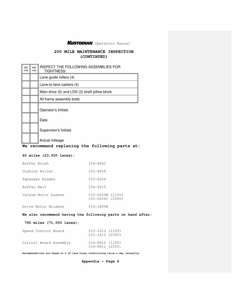
Operators Manual
Appendix – Page 6
200 MILE MAINTENANCE INSPECTION
(CONTINUED)
200 mile
400 mile
INSPECT THE FOLLOWING ASSEMBLIES FOR TIGHTNESS:
Lane guide rollers (4)
Lane-to-lane casters (4)
Main drive (5) and LDS (3) shaft pillow block
All frame assembly bolts
Operator's Initials
Date
Supervisor's Initials
Actual mileage
We recommend replacing the following parts at:
60 miles (23,500 lanes):
Buffer Brush 154-8641 Cushion Roller 153-8838
Squeegee Blades 153-8204
Buffer Belt 154-9615
Vacuum Motor bushes 153-0204B (115V) 153-0204C (230V)
Drive Motor Brushes 154-1809B
We also recommend having the following parts on hand after:
760 miles (71,000 lanes):
Speed Control Board 153-1012 (115V)
153-1812 (230V)
Circuit Board Assembly 154-8810 (115V) 154-8811 (230V) Recommendations are based on a 32 lane house conditioning twice a day (annually)

Operators Manual
Appendix – Page 7
B. Instructions To Clean Water Spray Pump
If water pump output is low, the valves inside the pump may be clogged. First clean or replace the Spray Jet Check Filters. Also check the length of the pressure regulator
tubing (length is 6" of 3/16" tubing). If pressure continues to be a problem, follow these
instructions to disassemble the FloJetTM pump and clean the valves. To prevent cleaner from leaking inside the motor, do
not remove the Diaphragm Assembly. (See the exploded view of the pump on Page 8.)
DISASSEMBLY:
1. Disconnect power and remove hoses from the pump. Use a rag to catch any cleaner before it spills on the
machine.
2. Get the pump out of machine by removing the 4 fasteners holding the pump to the rear wall.
3. With the pump on a workbench remove the Pump Head assembly. The Pump Head is attached by (4) long
phillips-head fasteners. (Note: There is no need to remove the (2) recessed screws.)
4. Remove the Pump Valve Assembly. This is the black
piece with grills that sits inside the pump head. Make
sure the O-ring is in the assembly.
5. Rinse the Pump Valve Assembly with warm soapy water, concentrating on the areas where the cleaner passes
through the grills. Do not pry on the black rubber pieces, as damage to these will ruin the valves.
ASSEMBLY:
1. Place the Valve Assembly (with the O-ring) on the Diaphragm.
2. Place the Pump Head over the Valve & Diaphragm
Assembly. Make sure the "direction of flow" arrow points from left to right as the pump sits flat on the base.
3. Insert (4) long #10-32 screws until each threads into
the Pump Motor, then tighten each screw securely.
4. Replace pump on rear wall with motor toward the top of the machine. Replace hoses and test for leaks.

Operators Manual
Appendix – Page 8

Operators Manual
Appendix – Page 9
C. Procedure For Cleaning Oil Control Valves
The following steps outline the procedure for disassembling
the conditioner metering valve. Be careful when removing the oil lines from the fittings since they will leak.
Block off the stem elbows to prevent them from leaking all
over the machine (do not split the stem). Open 1/4" lines can
be blocked off with a #8 screw.
Keep the oil lines and the valve free from dirt and debris while they are disassembled. Clean up any conditioner spills
immediately, the sensors and electronic components do not like oil baths.
1. Disconnect power and place the machine in the operating position.
2. Remove the oil tank from the rear wall.
3. Clean the area around the tank.
4. Use a Phillips screwdriver to remove the two screws holding the valve to the rear wall.
5. Remove the stem elbow connected the oil tip line on the valve. PUSH IN on the outer collet to release the
elbow. Also release the other oil line. Plug the open end of the elbow and the line to prevent dirt from entering and to stop the oil from leaking (do not split
the elbow).
6. Use a 9/16" open-end wrench to remove the bottom half of the valve. Do not pinch the small wires on the base of the valve. Keep track of the thin shim washers on
the valve. Make sure to use the same washers during re-assembly.
Comment [PC1]:

Operators Manual
Appendix – Page 10
7. The top section of the valve should be blown out with a canister of compressed air. Air should flow freely from the bottom through both sides at the top. A few short bursts of
canned air in both holes should displace any debris. Alcohol can also be used to remove any build-up of sediment.
NOTE: Do not use an air compressor to blow out the valve, water in the lines may be forced into the manifold.
8. The bottom section contains a plunger and spring. Make sure the three grooves on the sides of the plunger are clean. This part should be cleaned with a cotton swab and alcohol to
remove the debris.
IMPORTANT: If a valve is found to have only one groove please contact Kegel for an immediate replacement. All machines
should have the "high flow" valves, which are machined with
three grooves. Please call (863) 734-0200 if a replacement is needed.
9. Replace the valve body on the head of the valve using the same shim washers.
10.Replace the valve on the rear wall.
11.Plug the elbow and line back into the proper fitting and clean around all the connections.
Keep track of
thin shim washers on
each valve
Don’t pinch the
wires with 9/16ths wrench
High Flow
Plunger with three grooves

Operators Manual
Appendix – Page 11
12.Return the oil tank to the machine and plug in the connections.
13.Run the PUMP OUTPUT VOLUME TEST. Run this test once to clear the lines out; then check the volume of conditioner output for
a typical program and adjust the pump if necessary.

Operators Manual
Appendix – Page 12
D. Operators Menu Selections
* THE KUSTODIAN
SPEED 00 PRO#03
* MANUAL REVERSE
PRESS BUTTON
CHANGE PROGRAM
CHOOSE -> 03
SYSTEM CONTROL
CLEANING
SYSTEM CONTROL
DUSTER
START CLEANING
00 DISTANCE 00
SPRAY ON TIME
IN TENTHS -> 04
UNWIND TIME
F6 TO RESET 10
OIL ONLY DUST?
01 1-YES,0-NO 01 SPRAY OFF DIST
IN INCHES -> 30
OIL PATTERN DIST
37 IN FEET 37
LAST SPRAY DIST
IN FEET -> 45
01F 2L- 2R X 04
00->10 FT IPS=18
DECK SPRAY??
01=YES -> 01
02F 9L- 9R X 01
10->12 FT IPS=18
FORWARD DISTANCE
SUBTRACT -> 30
03F 10L-10R X 02
12->17 FT IPS=18
REVERSE DISTANCE
SUBTRACT -> 31
04F 11L-10R X 03 17->26 FT IPS=22
05F 12L-12R X 01
26->29 FT IPS=22
06F 13L-13R X 01
29->32 FT IPS=22
07F 13L-13R X 00
32->40 FT IPS=22
01R 2L- 2R X 00
40->28 FT IPS=26
02R 12L-12R X 02
28->23 FT IPS=18
03R 11L-11R X 02
23->18 FT IPS=18
04R 10L-10R X 02
18->13 FT IPS=18
05R 8L- 8R X 1
13->11 FT IPS=18
06R 8L- 8R X 1
11->10 FT IPS=14
07R 2L- 2R X 00
10->00 FT IPS=14
NEXT TO REVIEW
* MENU TO EXIT *
NOTE: The values shown in these tables are sample screens and may not reflect the actual default menu settings for the machine.

Operators Manual
Appendix – Page 13
Operators Menu Selections (Continued)
7 DAY PROGRAM
PLANNER
TEST OUTPUT #01
PRESS F2-F5 OFF
PUMP OUTPUT
VOLUME TEST
(C) COPYRIGHT
KEGEL CO 2002 9A
* MONDAY **** AM--> 01
TEST OUTPUT #02 PRESS F2-F5 OFF
* OIL VOLUME PRO#01 PRESS F6
* MONDAY
**** PM--> 01
TEST OUTPUT #03
PRESS F2-F5 OFF
* TUESDAY
**** AM--> 01
TEST OUTPUT #04
PRESS F2-F5 OFF
* TUESDAY
**** PM--> 01
TEST OUTPUT #05
PRESS F2-F5 OFF
* WEDNESDAY
**** AM--> 01
TEST OUTPUT #06
PRESS F2-F5 OFF
* WEDNESDAY
**** PM--> 01
TEST OUTPUT #07
PRESS F2-F5 OFF
* THURSDAY
**** AM--> 01
TEST OUTPUT #08
PRESS F2-F5 OFF
* THURSDAY
**** PM--> 01
TEST OUTPUT #09
PRESS F2-F5 OFF
* FRIDAY
**** AM--> 01
TEST OUTPUT #10
PRESS F2-F5 OFF
* FRIDAY
**** PM--> 01
TEST OUTPUT #11
PRESS F2-F5 OFF
* SATURDAY
**** AM--> 01
TEST OUTPUT #12
PRESS F2-F5 OFF
* SATURDAY **** PM--> 01
TEST OUTPUT #13 PRESS F2-F5 OFF
* SUNDAY
**** AM--> 01
TEST OUTPUT #14
PRESS F2-F5 OFF
* SUNDAY
**** PM--> 01
TEST OUTPUT #15
PRESS F2-F5 OFF
TEST OUTPUT #16
PRESS F2-F5 OFF
TEST OUTPUT #17
PRESS F2-F5 OFF
For an explanation of each menu read Section IV.

Operators Manual
Appendix – Page 14
E. Troubleshooting Outputs and Inputs
Troubleshooting of the machine is simplified by the Test
Output menu and the LED lights. This allows the operator to activate an Output and check that it is functioning properly.
Refer to Section VII to see a list of the Inputs and Outputs for the machine.
1. Outputs
Apply power to the machine and menu to TEST OUTPUT. The screen will display:
TEST OUTPUT #01
PRESS F2-F5 OFF
To test Output #01, press the F5 key. Output #01 in this case is the Reverse relay. The display will change to "ON" and the relay coil will engage. As soon as the key is released the
output will go off.
Press the F2 key and the display will change to:
TEST OUTPUT #02
PRESS F2-F5 OFF
To test Output #02 press and release the F5 key. Output #02 is the Forward drive relay. The display does not change to "ON", it will start displaying the speed of the drive motor. To turn
the motor off, press F5 again and the display will change back to "OFF". The TEST OUTPUT menu is where the drive speeds are adjusted.
The Forward Drive Output and all of the Speed Relay Outputs will run the motor and display the respective speeds for viewing.
Refer to Section V for drive speed adjustments. Review the rest of the Outputs and watch their function.
LED lights on the PLC will come on as each output is activated, this can aid in troubleshooting. It is important that the operator understand how to use this menu. It can increase the
speed of diagnosing repairs and minimize "down" time.
NOTE: Refer to Section VII of the manual for a list of the Outputs and their number. The Outputs do not come on in the order they are shown on the PLC.

Operators Manual
Appendix – Page 15
2. Inputs
To test the Inputs the operator will have to manually
activate the device that sends the signal to the PLC. When the Input is activated, the LED light for that Input will light up
indicating a good circuit. Refer to Section VII for a list of all Inputs.
The mechanical switches are all wired to the Normally Open
side of the switch, so the switch in its normal position is OFF. Simply depressing the lever of the switch will activate the Input
and the LED will light.
The proximity sensors are also wired Normally Open. Passing a metal object in front of the face of the sensor will activate the Input; the LED on the sensor and the PLC will go on
and off (at the same time) as the metal object passes by the sensor.
NOTE: Mechanical switches and sensors can be damaged by dirty, oily conditions. Getting cleaner in a mechanical switch can "short" the switch and give a false input. The Input's LED may
be very dim, but it will still be received as a good signal.
IMPORTANT: The target passing in front of the board counting proximity switch must be a gap between 0.015" and 0.020" (0.38 mm
to 0.51 mm). Gaps greater than 0.035" (0.89 mm) may cause errors in operation of this sensor.
The target for the 2 head position sensors should be a gap of no more than 0.025" (0.63 mm) on each side. If the target is too
far away from the sensor, an L8 Error might occur.

Operators Manual
Appendix – Page 16
F. Machine Error Messages
The machine is equipped with Error Message Codes that
are displayed in the event the machine malfunctions. These message codes indicate the type of operational error that
has occurred with the machine.
ERROR CODE DESCRIPTION
T1 FORWARD TRAVEL ERROR
T2 REVERSE TRAVEL ERROR
B3 BRUSH DOWN ERROR
B4 BRUSH UP ERROR
D5 DUSTER UNWIND ERROR
D6 DUSTER WIND-UP ERROR
H7 OIL HEAD TRAVEL ERROR
L8 OIL HEAD TIMING ERROR
S9 SQUEEGEE UP ERROR
SA SQUEEGEE DOWN ERROR
In most cases, correcting the problem and resuming the machine after an Error Message is possible. In some
instances, the machine will need to be returned to the foul line and then re-started.
Follow the Error Message information shown here to get
several suggestions as to the reason the error occurred. Along with these suggestions there are troubleshooting
suggestions.

Operators Manual
Appendix – Page 17
The following is a list of the errors that may occur.
ERROR MESSAGE
** CODE T1 **
1. Machine is not seated on the lane, there are high gutters, or the drive wheels are slipping.
2. LDS signal failure or the LDS Shaft is binding. 3. Drive Motor or Speed Control failure. 4. Wire is loose or broken for the 0CH #07 Input circuit. 5. Go to the Test Output Menu and Check Output #02 Forward Drive
Relay. 6. Turn the LDS shaft and see if Input 0CH #07 is flashing
on the PLC as the wheel rotates.
If there is a definite Lane Distance Sensor failure, it is
possible to use the TACH sensor for the LDS functions. The operator will have to remove the wire off of Input 0CH #06 and put it in place of the wire that is on Input 0CH #07.
Connect the wire from #07 to #06 and remember to reverse the wires when the sensor is repaired or replaced. Exchanging the
wires will turn the TACH sensor into a Lane Distance Sensor.
NOTE: If the TACH sensor is used as a distance counting sensor the machine will run short (as much as a foot of travel). The
return distance will have to be adjusted while the machine is
configured to operate this way. Go to the SYSTEM CONTROL
CLEANING to adjust the return distance.

Operators Manual
Appendix – Page 18
ERROR MESSAGE
** CODE T2 **
1. The LDS Shaft is binding or the machine is not seated on the lane.
2. Drive Motor or Speed Control failure. 3. Wire is loose or broken for the 0CH #07 Input circuit. 4. Go to the Test Output Menu and Check Output #01 Reverse
Drive Relay.
5. Turn the LDS shaft and see if Input 0CH #07 is flashing on the
PLC as the wheel rotates.
ERROR MESSAGE
** CODE B3 **
Menu Out of the Program and Return machine to approach.
1. If Brush Lift Motor runs continuously, Input 0CH #05 is not getting the signal from the Brush Motor Down Switch.
2. If the Brush Lift Motor does not run, menu to the Test Output screen and check Output #09.
ERROR MESSAGE
** CODE B4 **
Menu Out of the Program and Return machine to approach.
This Error will occur at the end of the programmed oil distance.
1. If Brush Lift Motor runs continuously, Input 0CH #04 is not getting the signal from the Brush Motor Up Switch.
2. If the Program is RESET, the brush should park in the DOWN
position. If it does, this indicates the DOWN Switch is good.
3. If the Brush Lift Motor does not run, menu to the Test Output
screen and check Output #09.
NOTE: The Brush Lift Motor and the Squeegee Motor will both time-out in 9 seconds if the position switch it is looking for is not actuated. Before the motor "times-out", the machine should have stopped and displayed an error.

Operators Manual
Appendix – Page 19
ERROR MESSAGE
** CODE D5 **
Menu Out of the Program and Return machine to approach.
1. Duster cloth is empty; replace cloth. 2. One (or both) of the Duster Up Switches are stuck. Check if
Input 0CH #10 has an LED light showing on the PLC with the cloth unwound.
3. Duster did not unwind. 4. If the Duster Motor does not run, menu to the Test Output
and check Output #12.
ERROR MESSAGE
** CODE D6 **
Menu Out of the Program and Return machine to approach.
1. Duster motor did not operate, or the set screw is loose and the hub is slipping on the motor shaft.
2. Make sure the duster rolls are seated in the drive hubs and routed properly.
3. Check adjustment of Wind-Up Switches and see if Input 0CH #10 has an LED light showing on the PLC when each of the switches
is actuated.
4. If the Duster Motor does not run, menu to the Test Output menu and check Output #13.
ERROR MESSAGE
** CODE H7 **
1. Oil Head Motor stopped or did not start moving. 2. Board Counting proximity sensor is not working. 3. If the Oil Head Motor does not run, menu to the Test
Output screen and check Outputs #16 and #17. 4. Check the adjustment of the Board Counting sensor and
look for an LED on Input 0CH #01 to light up when the target passes in front of the sensor.

Operators Manual
Appendix – Page 20
ERROR MESSAGE
** CODE L8 **
1. This Error will appear if the PLC program doesn’t turn the oil control valve on as the head travels between the two
proximity sensors. The machine is programmed to oil when the head moves and it should never travel without oiling. This
error does not prevent the machine from running, but the Start Button on the handle must be pressed to resume
operation. 2. Check for a proper gap of 0.025" (0.64 mm) between the target
on the head and the proximity sensors on both sides of the machine. Also check the gap between the head timing target
and the timing sensor, which should be between 0.015" and 0.020" (0.38 mm to 0.51 mm).
3. Use the blacklight to monitor the loads as the machine travels on the lane. This will help you determine the
severity of the problem. Do not allow Head Timing problems to undermine the consistency of the machine.
4. Using the machine with the head out of adjustment will result
in missed or improperly placed loads. Adjust the sensor gaps
or head timing as soon as possible if this error occurs.
Refer to Section V for instructions on adjusting the head timing.
5. If the travel speeds of the machine are improperly set the
program may try to load oil up until the end of the pattern. This will not cause the Head Timing Error, however this problem should be fixed to eliminate improperly placed loads.
ERROR MESSAGE
** CODE S9 **
Menu Out of the Program and Return machine to approach.
1. If Squeegee Motor runs continuously, Input 1CH #01 is not getting the signal from the Squeegee Up Switch.
2. If Squeegee Motor does not run, menu to the Test Output screen and check Output #11.

Operators Manual
Appendix – Page 21
ERROR MESSAGE
** CODE SA **
Menu Out of the Program and Return machine to approach.
1. Machine was put on the lane before the Squeegee was lowered. 2. If Squeegee Motor runs continuously, Input 1CH #00 is not
getting the signal from the Squeegee Down Switch.
3. If Squeegee Motor does not run, menu to the Test Output screen and check Output #11.
This concludes the ERROR MESSAGES that are available.

Operators Manual
Appendix – Page 22
G. Technical Support Instructions
Please follow these steps if there is a problem with the
machine.
1. Obtain as much information about the problem as possible. Can you duplicate the problem? If so, write down the steps that cause it to occur. Keep in mind that the technical support person will have to fix your problem with the
information you provide. The more details you can provide the quicker they can find a solution.
2. Check for error messages while operating the machine. Investigate the suggestions shown in the Manual.
3. Go to the TEST OUTPUT menu and check all the Outputs. Test all the Inputs manually. If any of these do not work,
inspect the wiring to the component. Each Input and Output also has an LED on the Control Module. These lights can
also be used to monitor the machine’s functions during operation.
4. Check the Operators Manual or KOSI to see if it addresses your problem. This may give you enough information to solve
the problem yourself, or at least it gives you the background to communicate the problem more readily to a
technical support person. If all else fails...read the
manual!
5. If you still need to call for help, get the following information ready:
_______ Machine Serial Number (on bottom of machine)
_______ Machine Production Date (on bottom of machine)
_______ Installation Date
_______ Program Number Where Problem Occurs (if not all)
_______ Line Voltage Coming Into The Machine (AC)

Operators Manual
Appendix – Page 23
6. Get the machine powered-up near a phone before you call for help. You should also have a meter handy to check AC and DC voltages and continuity. (This is an especially helpful tool
during trouble-shooting.)
7. Call Kegel at (863) 734-0200 or Brunswick at (231) 725-4966. The Kegel factory is located in Lake Wales, Florida USA. Office hours are typically from 7:00 a.m. to 5:30 p.m. EST
Monday through Friday. Calls outside these hours will be handled by an automated message system. Once a message is taken, a tech will be notified and you will be called back as
soon as possible.
Following these steps before you call will allow a technical
support person to isolate and solve the problem much faster. Each time you call take notes on how the problem was solved to refer back to if the problem occurs again.

Operators Manual
Appendix – Page 24
H. Pressure Regulator Tubing Chart
The following ranges of conditioner viscosity have been
tested in the machine to determine the size and length of the pressure regulator tubing that is needed. Keep in mind that
these are only guidelines, temperature greatly affects viscosity and may change these results.
Testing was performed at 72-degrees Fahrenheit with a
variety of conditioners. Equipment is available to measure the viscosity of any conditioner. A Viscosity Cup,
Thermometer, and a Stopwatch are valuable tools if you are mixing your own blend of conditioner. Call Kegel for more
information on how to obtain this equipment.
Viscosity Range Length Size (OD) Conditioner
<10 6~7 Ft. 3/16" LV2 or U-300
~10 30 In. 3/16" DBA #501
~20 15 In. 3/16" Clear #801
~30 6 In. 3/16" Defense-S/Offense-HV
~40 36 In. 1/4" Special Blend ~50 12 In. 1/4" Clear Super 50
>60 *See Note 1/4" Special Blend
*Note: When using a conditioner with a higher viscosity than 60, use a 1/4" OD (6.35 mm) piece of tubing that is approximately 3" long (7.62 cm) and connect it between the Tee
Fitting and the Oil Control Valve Input Fitting. Store all the elbows, fittings, and lines in a safe place in case you
want to switch back to a lighter conditioner. The machine has been tested up to 100 centistokes. The Kustodian ships from the factory with about a 12" piece of 3/16" pressure regulator
tubing for Offense-HV (30.48 cm piece at 4.762 mm OD).
To purchase stock tubing for adjusting the regulator lengths order the following part numbers:
154-0202A - 1/4" OD Tubing Stock (Inch)
154-0202B - 3/16" OD Tubing Stock (Inch) 2001, The Kegel Company, Inc. LV2 is a registered trademark of Brunswick.
U-300 is a registered trademark of Perry-Austen. DBA #501, Clear #801, and
Clear Super 50 are registered trademarks of DBA Products. None of these
trademarks are affiliated with Kegel. Offense-HV & Defense-S are registered
trademarks of Kegel Bowling Technologies.

Operators Manual
SECTION XI - Mechanical Drawings
Table of Contents
Edition 01:04
Relay Detail Diagram
Electrical Wiring Diagram - 115V/60 Hz
Electrical Wiring Diagram - 230V/50 Hz
Terminal Block Diagram
Overhead View ................................ Figure 1
Bottom View .................................. Figure 2
Right Side ................................... Figure 3
Left Side .................................... Figure 4
Control Plate Assembly ....................... Figure 5
Lane Distance Sensor Assembly ................ Figure 6
Speed Control & Drive Motor ................. Figure 7
Cleaner Supply System ........................ Figure 8
Conditioning Assembly ........................ Figure 9
Conditioner Transfer Assembly ................ Figure 10
Squeegee Motor Assembly ...................... Figure 11
Duster Assembly .............................. Figure 12
Buffer Brush Lifting Motor Assembly .......... Figure 13
Attaching Parts Breakdown (Fasteners) ....... Page 1
Complete Parts List .......................... Page 1

Operators Manual
Νοτεσ