lane machine manual - kegel
TRANSCRIPT

Lane Machine Manual
REV 12:10
Crossfire Specifications
17-5600K Battery Crossfire (24VDC) Class I - Single Phase
115 Volts, 60 Hz, 13 Amps
Machine Dimensions
Width – 55 1/ 4" (140.34 cm)
Height – 16” Length – 38 3/4"
Weight: Crossfire- 310 pounds
Manual Part Number: 158-5600 First Edition

Safety First Machines rated at 115 Volts A.C. are for use on a nominal 120-volt circuit and machines rated at 230 Volts A.C. are for use on a nominal 240-volt circuit.
This product is intended for COMMERCIAL USE. To reduce the risk of fire, use only commercially available bowling lane cleaners & conditioners intended for machine application. This is a HEAVY piece of equipment, and care should be taken when lifting it into the transport position. Use the proper technique to lift and lower the machine, and get a partner to help lift it up and set it down whenever possible. Make sure to bend at the knees and use a back support or mechanical lift if needed. Kegel does sell an optional piece of equipment that can assist the operator when lifting and lowering the machine. It can be mounted next to the end pairs of lanes to significantly reduce the transitional weight of the machine. Large centers might consider getting one for each end of the center for more convenience. DO NOT operate the machine while standing up in the transport position. There is a POTENTIAL FOR INJURY due to moving parts. Refer all servicing to qualified personnel. This machine is designed and manufactured for many years of dependable service. To ensure the durability of this equipment please handle it carefully. Do NOT drop or bang the machine around. Disconnect power BEFORE filling the Supply Tank or the Conditioner Tank. Be careful not to overfill the tanks. Do not allow excess fluid to enter the electrical compartment or come into contact with any electrical components. WIPE UP spills immediately, and make sure all components are dry before applying power to the machine. Replace fuses with the same type (Slow Blow) and Amp rating as indicated on the original fuse (or refer to the wiring diagram). Failure to do so may result in DAMAGE to the machine. Please make sure the WARRANTY CARD is filled out and returned immediately. This will allow the manufacturer or distributor to notify you of potential problems and/or offer upgrades to machine as they become available. Register your machine on line at www.kegel.net . If you need assistance or more information about this equipment please contact Kegel in Lake Wales, Florida USA at (863) 734-0200.
Warning of Potential Injury: Moving Parts – To Reduce the Risk of Injury Always Disconnect Power Before Servicing!

NOTES:
TABLE OF CONTENTS PPRREEFFAACCEE ...................................................................................................... 1
CCHHAAPPTTEERR 11 .................................................................................................. 5 INSTALLATION & SETUP .............................................................................................................................. 5
Machine Inspection ................................................................................................................................ 5 Register your Lane Machine .................................................................................................................. 5 Care and Safety Procedures .................................................................................................................. 6 Theory of Conditioning Operation ......................................................................................................... 7 Daily Setup and Operation .................................................................................................................... 7
Moving / Transporting your Lane Machine ....................................................................................................... 7 Filling the Conditioner and Cleaner Tanks ........................................................................................................ 8
Powering up the Lane Machine ............................................................................................................. 9 Basic steps to operate your Crossfire ................................................................................................................. 9 Keypad Display ............................................................................................................................................... 10 Run Screen Information ................................................................................................................................... 11 Starting Your Machine ..................................................................................................................................... 11 Change Program Override ............................................................................................................................... 12
Keypad and Menus ............................................................................................................................... 12 Machine Error Messages.................................................................................................................................. 12 Manual Reverse ............................................................................................................................................... 13 Operator Menu Selections ................................................................................................................................ 13
Set Time & Day Menu .......................................................................................................................... 14 Maintenance & Storage ....................................................................................................................... 15
Cleaning Guidelines ......................................................................................................................................... 15 LANE MAINTENANCE 101.......................................................................................................................... 17
CCHHAAPPTTEERR 22 ................................................................................................ 19 Theory of Conditioning Operation ....................................................................................................... 19 Change Program Settings .................................................................................................................... 20 Auto Programming (7 Day Planner) ................................................................................................. 28 Adjustments .......................................................................................................................................... 30
Buffer Brush Adjustment ................................................................................................................................. 30 Maintenance ......................................................................................................................................... 31
Wicking Pads ................................................................................................................................................... 31 Buffer Brush .................................................................................................................................................... 31
Troubleshooting the Conditioning System ........................................................................................... 32 Conditioning Problems Indicated by Error Messages ...................................................................................... 32
Oil Patterns .......................................................................................................................................... 34 Troubleshooting ............................................................................................................................................... 34 Pattern Descriptions ......................................................................................................................................... 35
CCHHAAPPTTEERR 33 ................................................................................................ 36 CLEANING SYSTEM ................................................................................................................................... 36
Theory of Operation ............................................................................................................................. 36 Why do we Clean Lanes? ..................................................................................................................... 37 System Control Cleaning ..................................................................................................................... 38 System Control Duster ......................................................................................................................... 41
Resetting the Duster Cloth ............................................................................................................................... 41 Adjustments .......................................................................................................................................... 43
Momentary Wheel Adjustment ........................................................................................................................ 43 Spray Jet Adjustment ....................................................................................................................................... 43 Squeegee Assembly Adjustment ...................................................................................................................... 44 Squeegee Switches ........................................................................................................................................... 45
Maintenance ......................................................................................................................................... 46 Changing Duster Cloth .................................................................................................................................... 46 Cleaner Tank .................................................................................................................................................... 47 Recovery Tank ................................................................................................................................................. 47

Squeegee Blade Replacement .......................................................................................................................... 48 General Maintenance ....................................................................................................................................... 48
Troubleshooting the Cleaning System .................................................................................................. 49 Cleaning Problems Indicated by Error Messages ............................................................................................. 49 Cleaning Problems NOT Indicated by Error Messages .................................................................................... 51
Copyright ............................................................................................................................................. 53
CCHHAAPPTTEERR 44 ................................................................................................ 54 DRIVE SYSTEM .......................................................................................................................................... 54
Adjustments .......................................................................................................................................... 54 Drive Board Adjustments................................................................................................................................. 54
Maintenance ......................................................................................................................................... 56 Troubleshooting the Drive System ....................................................................................................... 57
Drive System Problems Indicated by Error Messages ..................................................................................... 57
CCHHAAPPTTEERR 55 ................................................................................................ 59 COMPUTER AND CONTROL RELAYS ........................................................................................................... 59
Programmable Logic Controller .......................................................................................................... 59 Testing an Input ................................................................................................................................... 60 Testing an Output ................................................................................................................................. 63
Outputs and Testing continued…. .................................................................................................................... 64 Fuses / Breakers .................................................................................................................................. 65 Control Relays...................................................................................................................................... 66 Troubleshooting ................................................................................................................................... 67
CCHHAAPPTTEERR 66 ................................................................................................ 68 BATTERY & CHARGING SYSTEM ............................................................................................................... 68
Batteries ............................................................................................................................................... 68 Battery Charger ................................................................................................................................... 69 E-Stop ................................................................................................................................................... 70
CCHHAAPPTTEERR 77 ................................................................................................ 71 TROUBLESHOOTING ................................................................................................................................... 71
Troubleshooting Index ......................................................................................................................... 71
CCHHAAPPTTEERR 88 ................................................................................................ 72 MECHANICAL DRAWINGS .......................................................................................................................... 72
Machine Descriptions and Part Numbers ............................................................................................ 72 Crossfire Wiring Diagrams .................................................................................................................. 86

1
PPRREEFFAACCEE
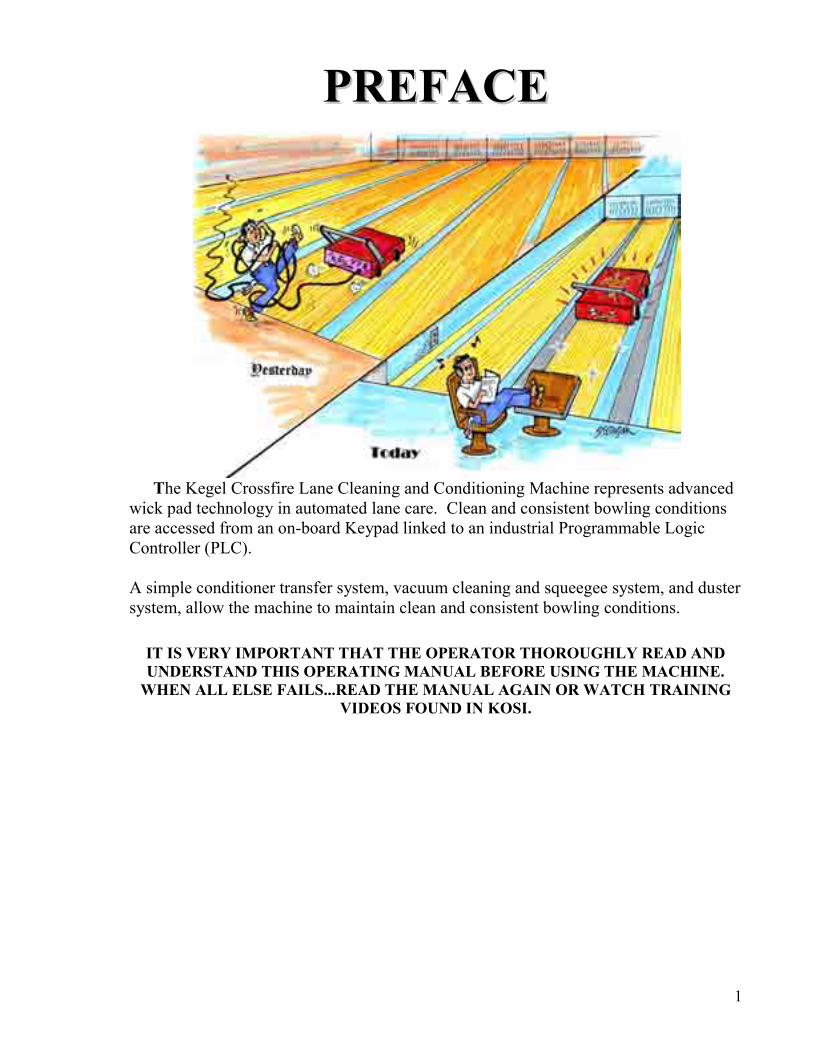
The Kegel Crossfire Lane Cleaning and Conditioning Machine represents advanced
wick pad technology in automated lane care. Clean and consistent bowling conditions are accessed from an on-board Keypad linked to an industrial Programmable Logic Controller (PLC). A simple conditioner transfer system, vacuum cleaning and squeegee system, and duster system, allow the machine to maintain clean and consistent bowling conditions.
IT IS VERY IMPORTANT THAT THE OPERATOR THOROUGHLY READ AND UNDERSTAND THIS OPERATING MANUAL BEFORE USING THE MACHINE.
WHEN ALL ELSE FAILS...READ THE MANUAL AGAIN OR WATCH TRAINING VIDEOS FOUND IN KOSI.

2
Copyright Notice All Rights Reserved. No part of this manual may be reproduced, stored in a retrieval system, or transmitted in any form or by any means, electronic, mechanical, photocopying, recording, or otherwise, without the prior written permission of Kegel. The information contained herein is designated only for use with the Kegel Crossfire Lane Machines. Kegel is not responsible for any use of this information as applied to other lane machines.
About This Manual This manual was prepared by the engineering, graphics & documentation departments of Kegel to provide detailed information and technical support about this lane machine and its operation. This manual was specially designed to educate the operator and ensure your investment is maintained properly.
The Intended User / Operator Although every attempt has been made to make this manual easy to understand and use, the operator should have basic electrical, mechanical and technical understanding to operate and maintain the Kustodian. Should you have any questions after reading this manual about proper operation or procedures, please contact Kegel at (863) 734-0200 or via email at [email protected] for technical support.
Disclaimer The identification of individuals, companies and products in this manual is provided for technical informational purposes only and does not constitute endorsement by Kegel of any business entity, service or products. Product brand names mentioned in this manual are trademarks or registered trademarks of their respective holders. Kegel disclaims any and all rights in those marks.
Trademark(s) Kegel, Kustodian Plus, Sanction Technology, Lane Maintenance Central, Navigation Series, Navigate, Offense, Defense, Prodigy, Infinity, Crossfire, Fizzion, Pure, and K2 EZ Core Kloth are registered trademarks or service marks of Kegel. All Rights Reserved.
Conformity Kegel is an ISO 9001 Certified Manufacturer. This lane machine has been independently tested to comply with applicable standards for the equipment. For additional copies of this or any other Kegel product manuals contact: KEGEL www.kegel.net 1951 Longleaf Blvd. (800) 280-2695 (Toll Free in the U.S.) Lake Wales, FL 33859 (863) 734-0200 USA © 2008 KEGEL
3
Kegel Company Background
Kegel was founded in 1981 by John Davis, Linda Davis, and David Jennings. At that time, Kegel had designed a small hand operated cleaning tool named “The Key”, which they manufactured in David’s garage. In 1983, Kegel purchased Ridge Lanes in Sebring, Florida and the crew moved south to run the bowling center and start Research & Development of lane maintenance and machines. The Sanction Machine® was soon developed and marketed as Kegel’s first fluid metering lane machine. In the following years many more machines were designed, such as the DBA LaneWalker, followed by the innovative LCM, Excel, Arrow, Phoenix, Phoenix-S, Standard, Kustodian, Sanction Walker, Kustodian Plus, Kustodian Ion, Kustodian Walker and the Crossfire. Manufacturing – Our core division designs and manufactures the world’s best lane conditioning and cleaning machines, replacement parts, and other specialized machinery products. Kegel Bowling Technologies – This division develops and blends conditioners and cleaners that are used in our lane conditioning machines, as well as other areas in bowling and beyond. Lane Maintenance Central (LMC) – Regarded by many as the best in the industry, LMC provides 24 hour telephone support, educational seminars, workshops, and on-site support to bowling centers and distributors throughout the world. Kegel Training Center – Located on-site, we custom built this 12-lane bowling center for serious bowlers to train to be the best. Kegel is proud to host educational clinics in various forms for bowlers, coaches and pro shop operators. The first of its kind, the Kegel Training Center boasts several original concepts including C.A.T.S. on every lane, adjustable topography lanes, and advanced coaching tools. Kegel has grown into a worldwide organization with several product divisions, over 100 employees, and a specially designed 72,000 sq. ft. state-of-the-art facility located in Lake Wales, Florida. Kegel has done this with a simple philosophy of researching the problems that exist in the bowling industry, developing a product or service to solve that problem, and making sure to support the customer with the highest of standards.

4
“Wah-lah…I did them the same!”

5
CCHHAAPPTTEERR 11
IInnssttaallllaattiioonn && SSeettuupp Machine Inspection It is important to identify all of the parts included with your lane machine and inspect its condition before you begin. Use the following list to make sure all parts are accounted for: Fill in the following Check Boxes and Information: □ Battery Crossfire Lane Machine - 17-5600K (115V)
□ (1) Funnel - 153-0052 (in Accessory Kit)
□ Accessory Kit
□ Operators Manual – 158-5200B
□ Extra Roll of EZ Core Cloth - 153-0047EZ
□ Maintenance Supplies Starter Kit - 154-8866
Date Unpacked: __________________________________ Unpacked by: ____________________________________ Machine Serial Number: ______________________ Register your Lane Machine It is important to register your new Battery Operated Crossfire with Kegel in order to receive valuable updates, service bulletins and your Limited Warranty. Fill out the card or go on-line. IMPORTANT: Please take a minute and register at: www.kegel.net .
6
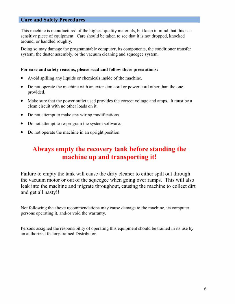
Care and Safety Procedures This machine is manufactured of the highest quality materials, but keep in mind that this is a sensitive piece of equipment. Care should be taken to see that it is not dropped, knocked around, or handled roughly.
Doing so may damage the programmable computer, its components, the conditioner transfer system, the duster assembly, or the vacuum cleaning and squeegee system.
For care and safety reasons, please read and follow these precautions:
Avoid spilling any liquids or chemicals inside of the machine.
Do not operate the machine with an extension cord or power cord other than the one provided.
Make sure that the power outlet used provides the correct voltage and amps. It must be a clean circuit with no other loads on it.
Do not attempt to make any wiring modifications.
Do not attempt to re-program the system software.
Do not operate the machine in an upright position.
Always empty the recovery tank before standing the machine up and transporting it!
Failure to empty the tank will cause the dirty cleaner to either spill out through the vacuum motor or out of the squeegee when going over ramps. This will also leak into the machine and migrate throughout, causing the machine to collect dirt and get all nasty!!
Not following the above recommendations may cause damage to the machine, its computer, persons operating it, and/or void the warranty.
Persons assigned the responsibility of operating this equipment should be trained in its use by an authorized factory-trained Distributor.

7
Theory of Conditioning Operation
This machine uses several felt wicking pads to transfer conditioner from a small reservoir to the transfer roller. A motor-driven camshaft controls the position of these pads during operation.
When the pads are in contact with the transfer roller conditioner will be applied. When the cams rotate they will push the pads away from the roller and no more conditioner will be applied.
The felt wicking pads are located in a trough that can be upgraded to maintain a consistent level of conditioner (with the optional tank). A valve opens on the optional tank when the float switch indicates the level is low. This provides consistent conditioner application from lane to lane without the need to constantly re-fill the supply tank.
It is important to let the wicks completely saturate with conditioner by performing the priming procedure BEFORE operating the machine on the lane. Allow the machine to set about 10 minutes in the operating position so the wicks can saturate and the trough can fill properly.
The type of conditioner will greatly affect the amount of output from the machine. However, there are three drive speeds available when conditioning to help control the flow of conditioner. To buff more conditioner on the lane the machine should travel at a slower speed.
Before transporting the machine after conditioning lanes, allow the trough to drain back into the tank. Allow it to drain completely BEFORE moving the machine up or down any ramps. Wait a couple of minutes with the machine in the transport position to ensure the trough is empty.
Daily Setup and Operation Moving / Transporting your Lane Machine You would think that transporting and moving your machine to and from the approach is an easy task, but some places can be difficult. Be careful when moving the machine.
Ramps that are used for moving the machine to and from the approach should also be “machine friendly”. These ramps should be no less than 12 feet long with no bump on either end of the transition. Improving these transitions will not only extend the life of your machine, but can make it easier to transport the machine to and from the approach.
The transition from the gutter to the approach should be as smooth as possible for an easy entrance and exit for the lane machine. This will prolong the life of the casters as well as other parts. Better transitions also help in preventing drips of cleaner from falling off the squeegee. It may seem like a lot of work to improve these areas (and it is in some cases) but it is well worth the time and effort. You should have no problem fitting this project in between pinsetter repair, scoring problems, glow bowl light repair, lane repair, plumbing, electrical work, carpentry and who knows what else…

8
Filling the Conditioner and Cleaner Tanks
Filling the Conditioner Tank
1. To fill the conditioner tank, the machine should be in the operating position on the lane. Open the lid assembly and remove the cap located on the top of the tank.
2. Insert the funnel assembly provided with the machine. Wrap a rag around the bottom of the funnel to prevent spills from getting in the machine.
3. Fill the tank until the conditioner level in the tank is about 1-1/2" (3.8 cm) from the top edge. Failure to watch the tank level could cause the tank to overflow. This overflow can drain down onto the lane distance sensor or the buffer brush, which will cause an excessive amount of conditioner to be applied to the lane in that area for several lanes. You should place rags beneath the tank to prevent this from happening.
When finished, be sure to remember to replace the cap.
Failure to do so could cause a major spill when the machine is lifted up to the transport position.
Filling the Cleaner Supply Tank Make sure your splash guards are in place prior to filling the tank. This will help protect your electrical components.
1. To fill the Cleaner Supply Tank, the machine should be in the down or operating position on the lane. Prepare an appropriate mixture of cleaner and water. Open the splash guard and place a rag beneath the tank. Open the tank cap and place a rag around the base of the funnel to prevent foam from over-flowing into the machine.
2. Slowly pour the mixture into the Cleaner Supply Tank using the supplied funnel until the level in the tank is about 1/2" (1.3 cm) below the top of the tank. This will prevent an air pocket from forming and blocking the fluid flowing from the funnel. Replace cap tightly when finished.
NOTE: Always use the funnel supplied with the machine. This funnel has a plastic filter screen. This screen filters out large debris and trash to prevent this from contaminating the supply tank and cleaning system. Not using a funnel with a filter may cause the tank's internal filter to become clogged frequently and reduce the cleaner output, resulting in inadequate cleaning. This may lead to customer complaints, ball calls and an excess of out-of-range pins. When necessary, the supply tank can be removed for cleaning.

9
Do not spill cleaner on the electrical components. Spills may cause a "short", which may send a false signal to the PLC causing improper operation. A wet switch may also produce a dim LED light on the PLC.
Any spills or drops of cleaner onto the approach should be wiped up immediately!
Any spills on the machine can stain the paint and make the machine ugly. Ugly machines do not run as well as clean, sharp, and highly maintained machines.
NOTE: If the lanes are going to be cleaned, make sure the Cleaner Supply Tank is filled, the Recovery Tank is empty, and an adequate supply of Lane Cleaning Cloth is installed before beginning operation. Always empty the recovery tank when filling the supply tank or standing the machine to transport position. Powering up the Lane Machine Basic steps to operate your Crossfire Carefully set the machine in the operating position on the approach. It should be completely on the approach, with the cleaning end being approximately 6 inches behind the foul line.
After removing the charging cord from the lane machine, turn the E-stop to the on position. Next, press and hold the button located on the rear panel just below the keypad.
Press and hold this button and the PLC will begin its boot up sequence and you will then see a message on the screen that reads “Dialogue table reading impossible” and then Crossfire Run Screen will appear with ??? in the value positions until the boot up sequence is complete at which time real number values will appear with the correct voltages. The machine is now ready to run.
If the machine does not appear to have power after you have done the above sequence, check the E-STOP switch to make sure it hasn’t been accidentally pressed. Rotate the red button to reset this switch. Power will resume immediately.

10
Keypad Display
The keypad display is a four line LCD (Liquid Crystal Display). During operation and selection of programs, various prompts, which are simply questions or data requests, will appear in the display, along with possibly some numbers.
The prompts will request the operator to input or change data or information within the selecting menu. The numbers will display cleaning and/or conditioning program numbers, distances (feet or "counts"), and various settings. What the prompts and numbers mean for each menu is explained under each menu heading in this section.
In some menus there will be only one number in the lower right hand corner. This will be the value of the menu prompt displayed. By using the UP ARROW or DOWN ARROW you can change the value (there is no need to press the enter key). The value is set when the number is changed.
In other menu screens, where multiple variables can be changed, the variable that can be changed will be blinking. Pressing the ENTER key will advance the blinking value to the next variable. This is used in the CHANGE PROGRAM area.
= Menu Reverse if arrow is present = Menu Forward if arrow is present
= Arrow Down keys used to decrease values = Arrow Up keys used to increase value
ESC = Escape key is used to return to the main menu MOD = Modify key must be pressed before you are allowed to change a value ENTER = Enter key is pressed to accept any changes or advance in the Sub menus
11
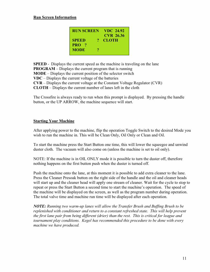
RUN SCREEN VDC 24.92 CVR 26.36 SPEED ? CLOTH PRO ? MODE ?
Run Screen Information
SPEED - Displays the current speed as the machine is traveling on the lane PROGRAM – Displays the current program that is running MODE – Displays the current position of the selector switch VDC – Displays the current voltage of the batteries CVR – Displays the current voltage at the Constant Voltage Regulator (CVR) CLOTH – Displays the current number of lanes left in the cloth The Crossfire is always ready to run when this prompt is displayed. By pressing the handle button, or the UP ARROW, the machine sequence will start. Starting Your Machine
After applying power to the machine, flip the operation Toggle Switch to the desired Mode you wish to run the machine in. This will be Clean Only, Oil Only or Clean and Oil. To start the machine press the Start Button one time, this will lower the squeegee and unwind duster cloth. The vacuum will also come on (unless the machine is set to oil only). NOTE: If the machine is in OIL ONLY mode it is possible to turn the duster off, therefore nothing happens on the first button push when the duster is turned off. Push the machine onto the lane, at this moment it is possible to add extra cleaner to the lane. Press the Cleaner Presoak button on the right side of the handle and the oil and cleaner heads will start up and the cleaner head will apply one stream of cleaner. Wait for the cycle to stop to repeat or press the Start Button a second time to start the machine’s operation. The speed of the machine will be displayed on the screen, as well as the program number during operation. The total valve time and machine run time will be displayed after each operation. NOTE: Running two warm-up lanes will allow the Transfer Brush and Buffing Brush to be replenished with conditioner and return to a constant refreshed state. This will help prevent the first lane pair from being different (drier) than the rest. This is critical for league and tournament play conditions. Kegel has recommended this procedure to be done with every machine we have produced.

12
Change Program Override In the RUN SCREEN it is also possible to do a program override. By pressing the MOD key and then press the UP ARROW or DOWN arrow to choose the program that is desired. By pressing ENTER, once chosen the machine is ready. Note: When power is removed from the machine the override feature will be disabled and the machine will return to its original auto programming. Keypad and Menus Machine Error Messages
The machine is equipped with Error Messages that are displayed on the Keypad in case the machine malfunctions. These messages will indicate the type of operational error that has occurred. Here are some descriptions of how some common causes of these errors may occur.
FORWARD TRAVEL
REVERSE TRAVEL
BRUSH DOWN
BRUSH UP
DUSTER UNWIND
DUSTER WINDUP
SQUEEGEE DOWN
SQUEEGEE UP CAM INDEX OIL TANK FLOAT PRIME PUMP TEST SCREEN ERROR

13
In most cases, correcting the problem and resuming the machine after an Error Message is possible. In some instances, the machine will need to be returned to the foul line and then re-started.
Follow the Error Message information shown here to get several suggestions as to the reason the error occurred. Along with these suggestions there are troubleshooting suggestions.
Manual Reverse In the event the lane machine should happened to be needed to return to the foul line, simply Operator Menu Selections The machine has a series of menus that are accessed from the RUN SCREEN. By pressing F1, which is also the MENU key, you will be able to toggle through to view the specific screen you are looking for. Each of these menus will be explained in detail in the appropriate section of this manual.
RUNS SCREEN
MANUAL REVERSE MENU
PROGRAM OVERRIDE MENU
SYSTEM UPGRADE MENU
CHANGE PROGRAM MENU
SYSTEM CONTROL CLEANING
SYSTEM CONTROL DUSTER
7 DAY PROGRAM PLANNER
TEST OUTPUT After the Test Output screen, there will be 3 screens to check your speeds with. Refer to Chapter 4 on how to do this.
COPYRIGHT After the Copyright screen, you will able to set the Time and Day for your lane machine. After the Set Time & Day menu, you will be able to Check the function of you all of your switches using the Test Input function. Refer to Chapter 5.

14
SET TIME & DAY CURRENT TIME
xxx AM PASSWORD xxx
SET TIME
TIME xxxx AM
Set Time & Day Menu By pressing the right arrow you will be able to toggle to the below screen:
This screen displays the current time and will flash quickly to the below screen to make changes..
You can change the current time by pressing the MODIFY key and moving the menu button (using the left and right arrow keys) over the number you need to change. Once you have changed that value press and hold the ENTER key until the screen advances.

15
Maintenance & Storage Cleaning Guidelines We’ve all heard the saying “Man, that Lane Machine cost more than my car”!! The fact of the matter is, you can get a pretty nice ride with the money spent on a new Lane machine. So why not treat it like one! Do those things that you would do to your car like the preventive maintenance, washing it, changing the oil and giving it that special attention that it deserves. Cleaning is the single most important thing the operator can do for this lane machine and it is not hard. Not taking the time to do simple cleaning will result in the downward spiral of your conditioning program. The end result will be a machine that is not reliable, and customers may begin to think they are bowling the Petersen Classic™. For those who do not know, the Petersen Classic™ is a tournament where the conditions are sometimes worse than bowling in a parking lot. It is the only place on the planet where the lane man gets no grief from the players since no one cares if two lanes play the same. Keeping your machine clean also helps you find potential problems. Loose fasteners or wires can be found and fixed before they interfere with normal lane maintenance. A good cleaning program is worth a few extra minutes per day.
Daily Cleaning
First things first, you should never transport the machine with waste in the recovery tank!
The oil compartment should be wiped down completely. Do not clean the Transfer
Brush or Buffing Brush excessively unless needed.
Clean the Drive, Lane Distance and Momentary wheels. Dust and lint should not be allowed to build up.
Wipe squeegee clean and inspect frequently for wear. Keep an extra set of blades on
hand (store them in a dark cool place).
Wipe down the bottom of the machine (this area collects a lot of dust).
Wipe off the outside of the machine.
16
Weekly or Monthly Cleaning
Use compressed air to remove dust from those hard to reach areas.
Inspect recovery tank filter.
Whenever the Duster cloth is changed, clean the entire cleaning compartment
Wipe off casters; they should not grow hair.
Remove large black covers and clean around the motors.
Inspect the motor end of the vacuum and make sure dust does not build up on the cover for the vacuum motor. Not keeping this clean will shorten the life of the motor.
Inspect the vacuum housing and investigate if wet.
Yearly Cleaning
Yearly cleaning is when you take the opportunity to do a little extra. Spend the entire day on the machine giving it extra care. Remove key components so you can get to some of those hard to reach areas. Scheduling a day or two would be a good thing.
17
LLaannee MMaaiinntteennaannccee 110011 Overview Bowling lane maintenance is more than just pushing a button on a lane machine and applying oil to the surface. It also requires giving attention to the approaches, gutters and capping which all get dusty. Maintaining all of this area on a daily schedule is important to provide the best service to your customers. Your lane machine also benefits from keeping these areas clean. Here are a few suggestions that should be followed to maintain your bowling center. 1. One of the first things that should be done each morning is a walk across the approaches.
This is when you find out if the lanes, gutters and approaches were dusted the night before. This is also great time to inspect the approaches for any kind of possible problems that just jump out at you. Very helpful on Saturday and Sunday morning after Rock N’ Bowl!
2. Walking the lanes each morning also gives you a chance to see what the left over oil looks
like in the applied area and what it looks like on the back-ends as well. It is possible to see many things, from unusual amounts of dirt to possible cleaning problems with the lane machine. Who knows what can be found?
3. Want to earn extra money? You just may find a couple of extra coins while Dusting the
gutters, caps and division rails each and every day. This greatly reduces the amount of dirt the lane machine pulls into the conditioning compartment. It sounds like a lot of work, but so what, it makes your life easier the more you run the machine. If you want to provide the best conditions it will take time. Also, it’s easier to keep up on a day-to-day basis.
4. Dust your approaches no less than three times a day… if not four. Some areas of the
country or world will require this just to keep them from looking like they were just plowed and ready for planting.
5. Dusting your lanes between conditioning is another big bonus that seems to be a lost art.
High lineage and dusty lanes are a bad combination, especially if your lanes are synthetic. Dust will increase the wear on the surface and reduce the life of your lanes, not including the changes that will result in the way the lanes react and play.
6. The approaches are very important to good customer satisfaction and you should pay close
attention to them. Besides frequent dusting, using a rotary buffer will improve the slide consistency and cleanliness of your approaches when done regularly.
7. Keeping your lane machine spotless will help you find problems before they become
nightmares. 8. Other areas that affect the cleanliness of your lanes is your pinsetters and ball returns
(anything that the bowling ball comes in contact with). Dirt comes from these things, along with grease and oil that is very difficult for the lane machine to clean off the surface.

18

19
CCHHAAPPTTEERR 22
Conditioning System
Theory of Conditioning Operation
This machine uses several felt wicking pads to transfer conditioner from a small reservoir to the transfer roller. A motor-driven camshaft controls the position of these pads during operation.
When the pads are in contact with the transfer roller conditioner will be applied. When the cams rotate they will push the pads away from the roller and no more conditioner will be applied.
The felt wicking pads are located in a trough that can be upgraded to maintain a consistent level of conditioner (with the optional tank). A valve opens on the optional tank when the float switch indicates the level is low. This provides consistent conditioner application from lane to lane without the need to constantly re-fill the supply tank.
It is important to let the wicks completely saturate with conditioner by performing the priming procedure BEFORE operating the machine on the lane. Allow the machine to set about 10 minutes in the operating position so the wicks can saturate and the trough can fill properly.
The type of conditioner will greatly affect the amount of output from the machine. However, there are three drive speeds available when conditioning to help control the flow of conditioner. To buff more conditioner on the lane the machine should travel at a slower speed.
Before transporting the machine after conditioning lanes, allow the trough to drain back into the tank. Allow it to drain completely BEFORE moving the machine up or down any ramps. Wait a couple of minutes with the machine in the transport position to ensure the trough is empty.
20
CROSSFIRE PROGRAM
PASSWORD ???
CHOOSE PROGRAM #
?
START CLEANING DISTANCE
CURRENTLY = ???
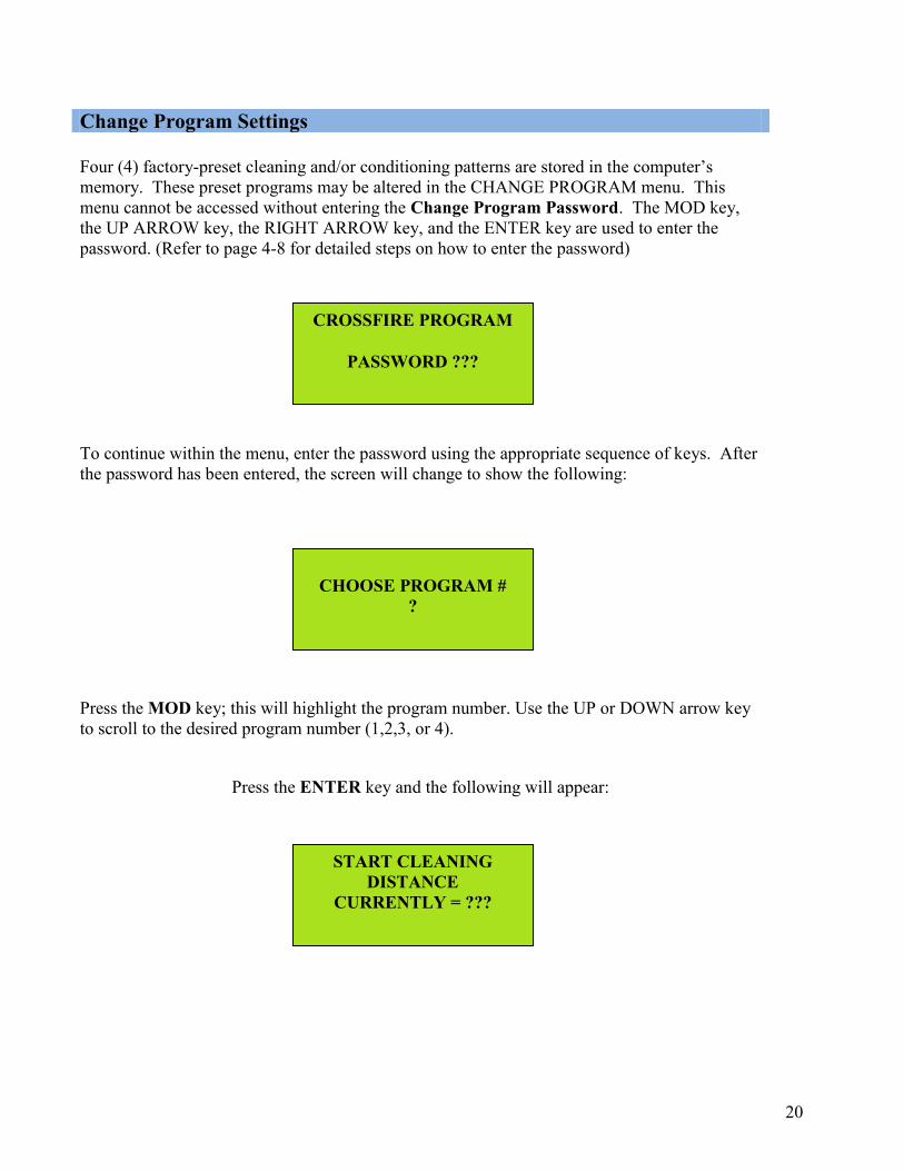
Four (4) factory-preset cleaning and/or conditioning patterns are stored in the computer’s memory. These preset programs may be altered in the CHANGE PROGRAM menu. This menu cannot be accessed without entering the Change Program Password. The MOD key, the UP ARROW key, the RIGHT ARROW key, and the ENTER key are used to enter the password. (Refer to page 4-8 for detailed steps on how to enter the password)
To continue within the menu, enter the password using the appropriate sequence of keys. After the password has been entered, the screen will change to show the following:
Press the MOD key; this will highlight the program number. Use the UP or DOWN arrow key to scroll to the desired program number (1,2,3, or 4).
Press the ENTER key and the following will appear:
Change Program Settings

21
OIL ONLY DUST
CURRENTLY ??
FORWARD SHIFT TO
SECOND SPEED CURRENTLY xx
FORWARD SHIFT TO
HIGH SPEED CURRENTLY xx
This prompt is referring to the distance at which the machine starts applying cleaner to the lane. A setting of “0” means the machine starts its cleaning cycle at the beginning of the lane. This number can be any number between 0 and 60. Each increment would be one foot further down the lane that the cleaning cycle would start.
To change the value, press the MOD key. Once the digit is highlighted, use the UP or DOWN ARROW key to change the number to the desired amount.
If this number is correct, press ENTER and the following will appear:
If the text displayed on this screen is “NO”, then the machine will not dust the lane in an “OIL ONLY” run. If the text is “YES”, the machine will dust the lane in an “OIL ONLY” run. To change the setting, use the combination of keys that are described on page 4-8.
Press ENTER and the following will appear:
The number displayed will refer to the distance in feet down the lane at which oil will be applied to the lane (this distance is for the current program that is selected). To change this number use the sequence of keys that is described at the top of page 4-8 (the maximum number that this distance can be is 56, the minimum value is 0).
Press the ENTER key and the following will appear:

22
ZONE 1 PADS OFF DISTANCE IN INCHES
CURRENTLY xx
ZONE 2 PADS OFF DISTANCE IN INCHES
CURRENTLY xx
This prompt will display the distance down the lane where the Crossfire will shift from Second Speed to High Speed. This example shows the machine traveling 10 feet in the second speed before shifting to high speed. To change this distance, use instructions at the top of page 4-8.
Press the ENTER key and the following will appear:
This is the distance from the foul line going forward that you have the Zone 1 or outside pads turn off. This setting is in inches. Once you have made your change or if the current setting is okay, press the enter key to advance to the next sub menu.
After pressing the ENTER key the following will appear:
Zone 1 Pad
Zone 2 Pad
Zone 3 Pad

23
ZONE 3 PADS OFF DISTANCE IN INCHES
CURRENTLY xx
8 PAD OPTION NOT ENABLED
ZONE 4 PADS OFF DISTANCE IN FEET
CURRENTLY xx
This is the distance from the foul line going forward that you have the Zone 2 pads turn off. This setting is in inches. Once you have made your change or if the current setting is okay, press the enter key to advance to the next sub menu.
Press the ENTER key and the following will appear:
This is the distance from the foul line going forward that you have the Zone 3 pads turn off. This setting is in feet. Once you have made your change or if the current setting is okay, press the enter key to advance to the next sub menu.
Press the ENTER key and the following will appear:
This prompt tells the operator that the machine is not set up with the 8 Pad option. The machine still has the factory installed 6 Pad set up.
If the machine does have the 8 Pad upgrade installed, the following screen will appear:
This is the distance from the foul line going forward that you have the Zone 4 pads turn off. This setting is in feet. Once you have made your change or if the current setting is okay, press the enter key to advance to the next sub menu.

24
FORWARD TRAVEL BUFF OUT DISTANCE
CURRENTLY xx
REVERSE SHIFT TO SECOND SPEED
CURRENTLY xx
REVERSE SHIFT TO LOW SPEED
CURRENTLY xx
After pressing the ENTER key the following will appear:
This is the distance from the foul line going forward that you set the machine to start the buff out. When this distance is shorter than the oil pattern distance it will turn off the transfer roller at the specified distance. Once you have made your change or if the current setting is okay, press the enter key to advance to the next sub menu.
After pressing the ENTER key the following will appear:
With the machine traveling in reverse, this is the distance from the foul line that the lane machine shifts to second speed. This setting is in feet. Once you have made your change or if the current setting is okay, press the enter key to advance to the next sub menu.
After pressing the ENTER key the following will appear:
With the machine traveling in reverse, this is the distance from the foul line that the lane machine shifts to low speed. This setting is in feet. Once you have made your change or if the current setting is okay, press the enter key to advance to the next sub menu. After pressing the ENTER key the following will appear:
25
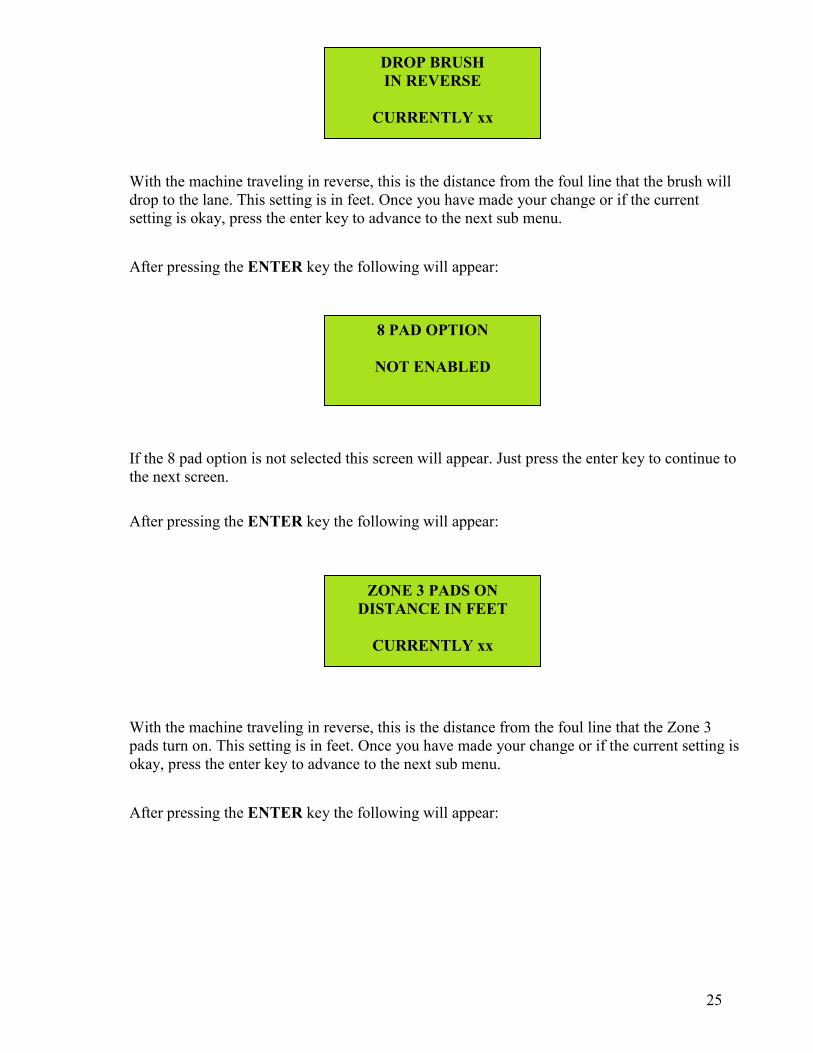
DROP BRUSH IN REVERSE
CURRENTLY xx
8 PAD OPTION
NOT ENABLED
ZONE 3 PADS ON DISTANCE IN FEET
CURRENTLY xx
With the machine traveling in reverse, this is the distance from the foul line that the brush will drop to the lane. This setting is in feet. Once you have made your change or if the current setting is okay, press the enter key to advance to the next sub menu.
After pressing the ENTER key the following will appear:
If the 8 pad option is not selected this screen will appear. Just press the enter key to continue to the next screen.
After pressing the ENTER key the following will appear:
With the machine traveling in reverse, this is the distance from the foul line that the Zone 3 pads turn on. This setting is in feet. Once you have made your change or if the current setting is okay, press the enter key to advance to the next sub menu.
After pressing the ENTER key the following will appear:

26
ZONE 2 PADS ON DISTANCE IN FEET
CURRENTLY xx
ZONE 1 PADS ON DISTANCE IN FEET
CURRENTLY xx
REVERSE BUFF TO FOUL LINE
IN FEET CURRENTLY xx
With the machine traveling in reverse, this is the distance from the foul line that the Zone 2 pads turn on. This setting is in feet. Once you have made your change or if the current setting is okay, press the enter key to advance to the next sub menu.
After pressing the ENTER key the following will appear:
With the machine traveling in reverse, this is the distance from the foul line that the Zone 1 pads turn on. This setting is in feet. Once you have made your change or if the current setting is okay, press the enter key to advance to the next sub menu.
After pressing the ENTER key the following will appear:
This is the distance from the foul line, when traveling in reverse, that the transfer roller will turn off. Once you have made your change or if the current setting is okay, press the enter key to advance to the next sub menu.
After pressing the ENTER key the following will appear:

27
PRESS THE ENTER KEY TO REVIEW
PRESS ARROW UP KEY TO EXIT
This screen asks you if you want to review all of change program screens. If you exit the change program area, you will return to the Change Program Main Screen.

28
7 DAY PROGRAM
PLANNER
SUNDAY AM PROGRAM
CURRENTLY xx
After pressing the ENTER key the following will appear:
This feature allows the machine to store specific conditioning programs to be used for each day of the week, within each time period of the day.
The "real time" clock in the machine's PLC keeps track of the time of day and will run the program selected for that specific time period. The time periods are not broken down by the hour, but rather are separated into two time categories, AM and PM.
For example, a conditioning program selected for Sunday AM means that operation of the machine any time between 12:01 AM and 12 Noon will apply that selected conditioner program.
To continue within this menu, press the ENTER key and the following prompt will appear:
Use the UP ARROW to change the program number and the value will be set. The DOWN ARROW does not function in these menu screens, the program number will loop back around to 01 if the UP ARROW is pressed with program 04 showing.
Press the ENTER key and the PM time period for Sunday will appear. Advance to the rest of the days of the week and enter the program numbers that you wish to run.
Auto Programming (7 Day Planner)

29
A program can be entered for each of the following time periods:
MONDAY AM MONDAY PM TUESDAY AM TUESDAY PM WEDNESDAY AM WEDNESDAY PM THURSDAY AM THURSDAY PM FRIDAY AM FRIDAY PM SATURDAY AM SATURDAY PM SUNDAY AM SUNDAY PM
NOTE: The machine will only run the program set for that day and time. If you wish to override a program, it will have to be changed in the appropriate day and time period.
This concludes the selections in the
7 DAY PROGRAM PLANNER menu.
30
Buffer Brush Adjustment
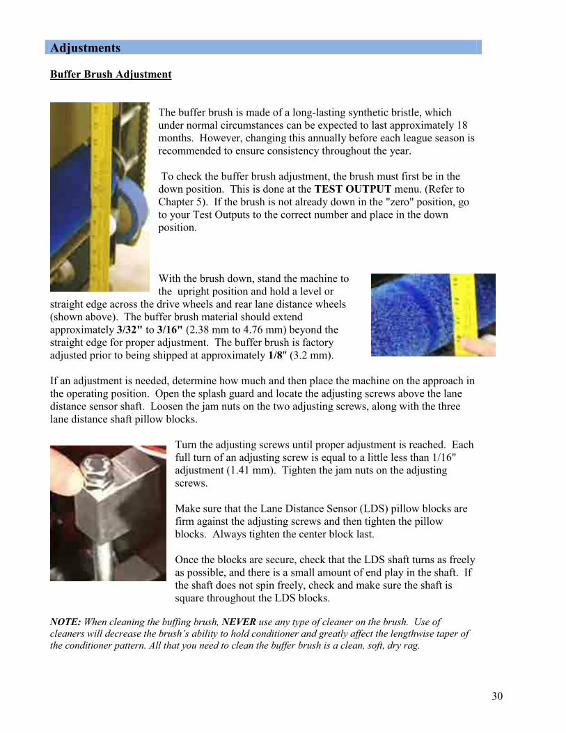
The buffer brush is made of a long-lasting synthetic bristle, which under normal circumstances can be expected to last approximately 18 months. However, changing this annually before each league season is recommended to ensure consistency throughout the year. To check the buffer brush adjustment, the brush must first be in the down position. This is done at the TEST OUTPUT menu. (Refer to Chapter 5). If the brush is not already down in the "zero" position, go to your Test Outputs to the correct number and place in the down position. With the brush down, stand the machine to the upright position and hold a level or
straight edge across the drive wheels and rear lane distance wheels (shown above). The buffer brush material should extend approximately 3/32" to 3/16" (2.38 mm to 4.76 mm) beyond the straight edge for proper adjustment. The buffer brush is factory adjusted prior to being shipped at approximately 1/8" (3.2 mm). If an adjustment is needed, determine how much and then place the machine on the approach in the operating position. Open the splash guard and locate the adjusting screws above the lane distance sensor shaft. Loosen the jam nuts on the two adjusting screws, along with the three lane distance shaft pillow blocks.
Turn the adjusting screws until proper adjustment is reached. Each full turn of an adjusting screw is equal to a little less than 1/16" adjustment (1.41 mm). Tighten the jam nuts on the adjusting screws. Make sure that the Lane Distance Sensor (LDS) pillow blocks are firm against the adjusting screws and then tighten the pillow blocks. Always tighten the center block last. Once the blocks are secure, check that the LDS shaft turns as freely as possible, and there is a small amount of end play in the shaft. If the shaft does not spin freely, check and make sure the shaft is square throughout the LDS blocks.
NOTE: When cleaning the buffing brush, NEVER use any type of cleaner on the brush. Use of cleaners will decrease the brush’s ability to hold conditioner and greatly affect the lengthwise taper of the conditioner pattern. All that you need to clean the buffer brush is a clean, soft, dry rag.
Adjustments
31
Wicking Pads The wicking pads will need to be replaced periodically. Cleaning any accumulation of dirt and dust from wicking pads after every conditioning run will extend their life. USE A SOFT RAG ONLY!! Metal or abrasives will tear at the wick material, causing wick deterioration and irregular conditioner flow.
WICKING PAD REMOVAL: To remove a wicking pad for cleaning or replacement, remove both springs from the eyebolts on the wick assembly. Pull the pad out of the trough. To replace the pad into the trough, simply reverse the procedure.
NOTE: When the wick pads are removed always inspect the trough for debris. Clean any accumulation out of the trough and inspect the area where the conditioner re-fills into it.
WICKING PAD CLEANING: To clean the wicking pads, wipe the wick material with a clean, dry cloth until all loose dirt particles are removed.
WICKING PAD REPLACEMENT: When it becomes necessary to replace the wick material on the Crossfire wicking pads, use only genuine Kegel replacement material. These items may be ordered from your Authorized Distributor. Any combination of pad sizes can be used, as long as the sizes of the six or eight pads all added together total 40-inches.
CHANGING OF CONDITIONER: It is not always necessary to replace the wicking pad material when the type of conditioner being used is changed. When changing conditioners, remove all wicking pads from the machine and drain the conditioner tank and trough completely.
Using a clean, dry towel, squeeze the wicking pads to remove as much of the old conditioner as possible. Use several towels if necessary. Before replacing wicking pads into the conditioner tank, saturate each pad with the new lane conditioner to be used. This can be done by using a dispenser such as a clean, empty ketchup bottle, or by laying the pads into a small shallow pan filled with about 1/2" of lane conditioner.
Once saturated, re-install all of the pads into the trough. Fill the tank with the new lane conditioner and allow the trough to become full.
Buffer Brush If build-up of dirt occurs, the brush should be wiped with a clean cloth. Do not use any type of cleaner. Cleaning agents can affect the material, which can change the brush’s ability to hold conditioner.
Maintenance

32
BRUSH NOT DOWN OR
UP SWITCH STUCK
BRUSH NOT UP OR
DOWN SWITCH STUCK
Conditioning Problems Indicated by Error Messages
Menu Out of the Program and Return machine to approach.
1. If Brush Lift Motor runs continuously, Input #00 is not getting the signal from the Brush
Motor Down Switch.
2. If the Brush Lift Motor does not run, menu to the Test Output screen and check
Output #02.
Menu Out of the Program and Return machine to approach.
This Error will occur at the end of the programmed oil distance.
1. If Brush Lift Motor runs continuously, Input #12 is not getting the signal from the Brush
Motor Up Switch.
2. If the Program is RESET, the brush should park in the DOWN position. If it does, this
indicates the DOWN Switch is good.
3. If the Brush Lift Motor does not run, menu to the Test Output screen and check Output #02.
Note: The Brush Lift Motor and the Squeegee Motor will both time-out in 9 seconds if the position switch it is looking for is not actuated. Before the motor "times-out", the machine should have stopped and displayed an error.
Troubleshooting the Conditioning System

33
CAM INDEX ERROR CHECK YOUR LANE TO
BE CERTAIN IT WAS OILED PROPERLY
OIL TANK FLOAT ERROR
CHECK TANK FOR OIL
1. Cam motor bad.
2. If Cam Motor does not run, menu to the Test Output screen and check Output #01.
3. Index Motor fuse is blown.
1. Flow of conditioner to the Wick Trough has stopped. If the machine has not
received a signal from the float switch in 10 lanes (on a normal clean/condition
program), the machine will error and prevent it from operating.
2. The float switch is stuck, indicating a full trough. Inspect the oil level to see if it is
below, or even with, the bottom of the wicking pads. Also inspect the area where
the float operates to check for free movement.
3. Check the viscosity of the conditioner to determine if it has changed. Oil gets
thicker in cold climates.

34
Troubleshooting Here are some suggestions to common questions about lane conditioning. These tips should help you make the proper adjustments to the patterns supplied in this manual. Q: What should I do if I have too much carry down? A: Shorten the applied oil distance. Too much oil in the middle, at the end of the pattern, causes carry down. Change only the buff-out distance, do not shorten the pattern, as this only creates more transition and possibly more moves. Make sure the machine is cleaning properly before making any pattern adjustments. Q: What should I do if the backends are too strong? A: Lengthen the pattern to tone down the reaction. Tamer backends provide predictable ball reaction and makes spare shooting easier. Be aware of potential carry down problems when the pattern length is increased. Q: What should I do if I do not have enough hold? A: The distance of the applied oil on the return pass creates hold. This area is known as the mid-lane (from about 18-32 feet). The mid-lane provides direction to the breakpoint and dictates the score-ability of a pattern. Starting the reverse oil farther down the lane will help increase hold. Q: What should I do if the heads hook? A: The amount of oil in the lay down area, or a lane surface in poor condition, can cause the heads to hook. In both instances, the lane machine should run slower in the heads. This is better controlled on the return oil due to the direction of travel and the rotation of the buffer brush. Apply conditioner during the return travel that finishes close to the foul line. Q: What should I do if I have no swing? A: The amount of oil on the outside boards, or adverse lane topography, can affect swing. Reducing the length (or volume) of the applied oil will increase the amount of swing. If this is a topography issue, the pattern should be adjusted by reducing the amount of oil on the outside boards to allow bowlers to play a more direct line to the pocket. This should create more area in play at the breakpoint.
Oil Patterns

35
Q: What should I do if the track dries up too quickly? A: Many bowling centers do not apply enough oil to the track on both forward and return passes. The volume, in units, at the end of the pattern should be slightly more than the outside boards. Applying oil to the track on the return pass provides longevity and stability. This application of oil can be started further down the lane on the return without drastically affecting the forward oil readings and ball reaction.
Pattern Descriptions These programs have been created specifically for the Crossfire lane machine. These graphs are only a representation of the patterns that will be applied by the machine. Many variables can affect the graph, so it may not match your machine exactly. Program 1 is designed for high friction surfaces that are in good shape, for some synthetics,
and freshly resurfaced lanes. Program 2 is similar to Program 1 with less applied oil distance for lower friction surfaces or
stronger backends. Program 3 has shorter applied oil going forward with more length on the return. Designed to
create more hold while limiting the carry down. Program 4 is a starting point pattern for competitive events, wider and flatter to create more
angles. Requires a higher skill level than a typical “house pattern”.

36
CCHHAAPPTTEERR 33
CClleeaanniinngg SSyysstteemm Theory of Operation The proper cleaning of your lanes is very important to the consistency of your playing conditions. Various things can cause the machine to not adequately remove the dirt and conditioner from your lanes. In this section we will describe how the machine cleans your lanes and reasons why it may not. The below sequence is an overview of how the Cleaning System operates.
1. When the machine sequence is started, the cleaner will dispense the first shot of cleaner
onto the lane wherever the “First Spray” is set to. As the machine travels down the lane, it will continue to dispense cleaner based on what the “spray on” and “spray off” numbers are set to.
2. As the machine travels forward, the cleaner will pass underneath the cushion roller and
will be wiped onto the surface of the lane. The special texture of the cushion roller wrap prevents the cloth from creating a seal against the surface of the lane and also allows it to follow the crowns and depression of a normal lane.
3. The heavy dirt, along with oil and conditioner, will get trapped in the cloth as it wipes the
lane. 4. The front blade of the squeegee then passes over the cleaner and the rear blade seals to the
surface of the lane. 5. The vacuum pulls the cleaner, dirt and oil from the squeegee and deposits it into the
recovery tank.

37
Why do we Clean Lanes?
The reason for cleaning lanes is to protect your investment. Not having a good lane maintenance program will not allow you to achieve the best results. The other reason is its just good customer service. Another reason would be to have your center create high scoring conditions (but that can also be achieved with poor maintenance). If you have synthetic lanes there is no room for error. Every scratch will be part of that surface forever and the more you do to prevent it, the longer they will last. When it comes to wood lanes, I guess you can say there is some room for error. You can always sand and re-coat the surface. Good maintenance for your wood lanes is important in protecting the finish and preventing it from glazing in the ball track. It is impossible to prevent this completely, but it can be slowed down.
38
SYSTEM CONTROL CLEANING
PRESS ENTER TO GET TO SUB MENUS
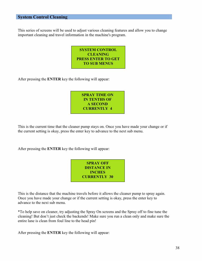
SPRAY TIME ON IN TENTHS OF
A SECOND CURRENTLY 4
SPRAY OFF DISTANCE IN
INCHES CURRENTLY 30
This series of screens will be used to adjust various cleaning features and allow you to change important cleaning and travel information in the machine's program.
After pressing the ENTER key the following will appear:
This is the current time that the cleaner pump stays on. Once you have made your change or if the current setting is okay, press the enter key to advance to the next sub menu.
After pressing the ENTER key the following will appear:
This is the distance that the machine travels before it allows the cleaner pump to spray again. Once you have made your change or if the current setting is okay, press the enter key to advance to the next sub menu. *To help save on cleaner, try adjusting the Spray On screens and the Spray off to fine tune the cleaning! But don’t just check the backends! Make sure you run a clean only and make sure the entire lane is clean from foul line to the head pin! After pressing the ENTER key the following will appear:
System Control Cleaning

39
LAST SPRAY DISTANCE IN FEET
CURRENTLY 52
DO YOU WANT TO SPRAY THE PIN DECK?
CURRENTLY NO
PINDECK SPRAY TIME ON
TIME 4 IN TENTHS
FORWARD DISTANCE SUBTRACT
DISTANCE IN INCHES CURRENTLY 25
This is the distance going forward that you want the last spray of cleaner on the lane before you reach the end of the lane. Once you have made your change or if the current setting is okay, press the enter key to advance to the next sub menu.
After pressing the ENTER key the following will appear:
This is a YES or NO question. By default it is set to NO. Under normal situations the normal cleaning is enough to clean the pin decks. In the case the pin decks are not getting cleaned you can answer YES to this question and the cleaner pump will spray one time on the pin deck. Once you choose your answer, press the enter key to advance to the next sub menu.
After pressing the ENTER key the following will appear:
This allows the operator to adjust the length of time that the pin deck spray stays on.
After pressing the ENTER key the following will appear:
40
REVERSE DISTANCE SUBTRACT
DISTANCE IN INCHES CURRENTLY 26
IS YOUR LANE LENGTH DIFFERENT FROM NORMAL LANES?
NO
ENTER YOUR LANE DIFFERENCE..NORMAL
CALCULATION IS 756 INCHES
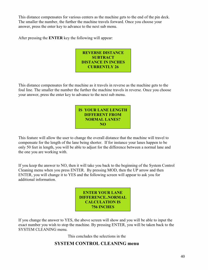
This distance compensates for various centers as the machine gets to the end of the pin deck. The smaller the number, the further the machine travels forward. Once you choose your answer, press the enter key to advance to the next sub menu.
After pressing the ENTER key the following will appear:
This distance compensates for the machine as it travels in reverse as the machine gets to the foul line. The smaller the number the further the machine travels in reverse. Once you choose your answer, press the enter key to advance to the next sub menu.
This feature will allow the user to change the overall distance that the machine will travel to compensate for the length of the lane being shorter. If for instance your lanes happen to be only 50 feet in length, you will be able to adjust for the difference between a normal lane and the one you are working with.
If you keep the answer to NO, then it will take you back to the beginning of the System Control Cleaning menu when you press ENTER. By pressing MOD, then the UP arrow and then ENTER, you will change it to YES and the following screen will appear to ask you for additional information.
If you change the answer to YES, the above screen will show and you will be able to input the exact number you wish to stop the machine. By pressing ENTER, you will be taken back to the SYSTEM CLEANING menu.
This concludes the selections in the
SYSTEM CONTROL CLEANING menu

41
SYSTEM CONTROL DUST
PRESS ENTER TO GET TO SUB MENUS
DID YOU CHANGE TO A NEW ROLL OF
DUSTER CLOTH? CURRENTLY xx
UNWIND RESET RECOMMENDED TIME IS 9 TENTHS SECOND
CURRENTLY xx
Resetting the Duster Cloth The following screens will be used to operate and reset the duster functions.
After pressing the ENTER key the following will appear:
After pressing the ENTER key the following will appear:
This asks the operator if the duster cloth was changed, and if you answer YES, it will change the duster unwind time to the system default. Once your answer is correct then press the enter key to advance to the next sub menu.
After pressing the ENTER key the following will appear:
This displays the current unwind time. This number increases by one number every 35 lanes to compensate for the unwinding of the cloth. You can increase or decrease this value from this screen by using the up or down arrow.
NOTE: Resetting the DUSTER counter prior to the roll of cloth being empty could reduce the cleaning efficiency of the machine. The cushion roller must be allowed to drop far enough to contact the lane. In this menu it is possible to correct the present unwind time if one of your pinchasers has presented you with this problem.
System Control Duster
42
DUSTER WINDUP A LITTLE LONGER
TIME xx IN TENTHS
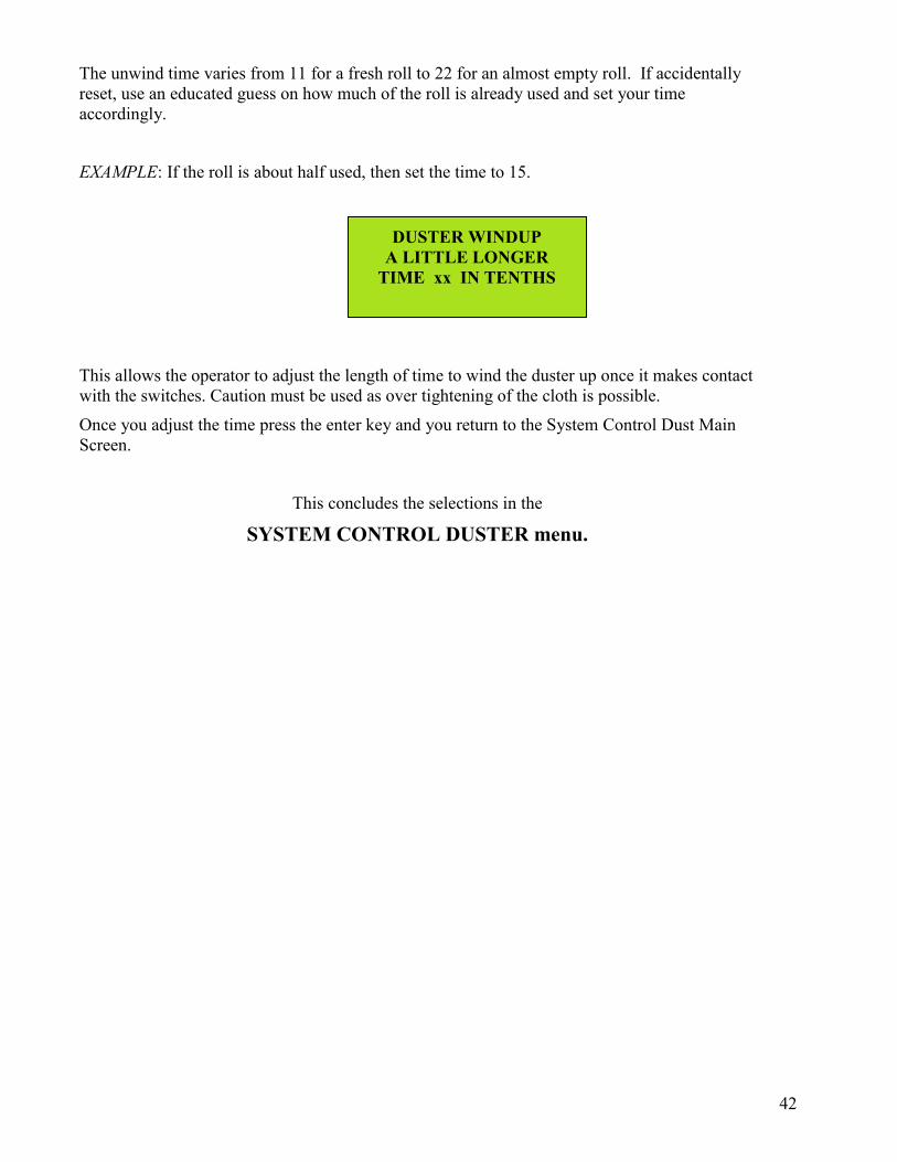
The unwind time varies from 11 for a fresh roll to 22 for an almost empty roll. If accidentally reset, use an educated guess on how much of the roll is already used and set your time accordingly.
EXAMPLE: If the roll is about half used, then set the time to 15.
This allows the operator to adjust the length of time to wind the duster up once it makes contact with the switches. Caution must be used as over tightening of the cloth is possible.
Once you adjust the time press the enter key and you return to the System Control Dust Main Screen.
This concludes the selections in the
SYSTEM CONTROL DUSTER menu.
43
Momentary Wheel Adjustment We like to call this the forgotten adjustment because no one does much with these wheels. To adjust the momentary wheels the machine will have to be stopped on the lane. Once the machine is on the lane, loosen (do not remove) the bolts that hold the momentary wheels to the machine. Slide the momentary wheel housings up or down until the gap between the wheels and the lane is approximately 1/16” to 1/8” (1.6 mm to 3.2 mm). The wheels need to be as close to the lane as possible without touching. For proper adjustment the lanes need to be relatively flat lengthwise. Tighten the bolts in the housing once the desired gap is achieved. Both momentary wheel housings should have the same height adjustment on both sides. NOTE: When the machine is pushed into the lane if you notice that an area close to the foul line is missed by the squeegee due to a depression (mainly on wood lanes or overlays), you will have to adjust the momentary wheels further up. This will allow the squeegee to touch the lane a little sooner.
Spray Jet Adjustment The machine uses a three spray jet system to spray cleaner onto the lane surface. These specially designed stainless steel jets spray in a "V" pattern and when properly adjusted spray cleaner across the entire width of the lane.
The spray jets are factory-set, but may need to be adjusted so all boards across the lane are covered, and so that overspray into the channels does not occur.
If coverage is too narrow and edge boards are not being sprayed, adjust by raising the spray tips slightly, or rotating the jet mounting angle.
If coverage is too wide and overspray occurs, adjust spray tip down or toward the center.
To adjust, simply loosen the hex bolt on the aluminum body of the spray assembly. Rotate the spray jet up or down as needed. The middle tip is at an angle, positioned at about a 45-degree or a 135-degree angle. Adjust this jet until you get the best spray pattern, then tighten hex bolt.
The mounting angles for the outside jets can be angled toward the center to eliminate any overspray into the channels. The tips of the outside jets should basically be positioned vertically.
Adjustments

44
Squeegee Assembly Adjustment
The Squeegee Assembly is adjusted at the factory to ensure proper cleaning. This adjustment should be checked when the machine is installed. The factory "zero" point is measured on the pivot mounts that secure the squeegee to the sides plates. We suggest the gap between the bottom of the side plate and the bottom of the pivot arm should be about 3/16" (4.76 mm) on both sides of the machine. Adjustments may vary depending on your lane characteristics.
To check this height adjustment and make changes, the machine should be in the upright or transport position. The squeegee will need to be lowered to the down position. Lower the squeegee by pressing menu until you get to the TEST OUPUT screen. Next, press F2 until you get to test Output #11. By pressing F5 you will be able to raise and lower the squeegee assembly.
With the squeegee down, take a straight edge and place it from the squeegee blade across the drive wheels to the lane distance wheels. The gap between the straight edge and the drive wheels should be about 1/8" to 3/16" (3.18 mm to 4.76 mm) on each side.
If the distance is more or less, loosen the bolts (two on each side) that hold the squeegee pivot in place. Move the pivot mount until the squeegee height is correct. This should be done for both the left and the right side. Tighten the bolts after the adjustment is acceptable.
Gap should be 1/8” – 3/16”

45
The tilt or pitch of the squeegee may also need adjustment to ensure that both blades are contacting the lane squarely. If a pitch adjustment is necessary, follow the steps below to make the adjustment. Make sure the squeegee motor does not bind up when making an adjustment. If the link is too short the motor cannot rotate 360.
1. Locate the squeegee motor on the right side plate of the machine. Mounted to the motor shaft (inside the machine) is a cam. Mounted to the cam is a rod end and rod. This rod lifts and lowers the squeegee (see diagram below).
2. Loosen the jam nut between the rod end and the rod.
3. Remove the bolt that connects the rod end to the cam.
4. Rotate the rod end as needed to increase or decrease the pitch. DO NOT make the linkage too short.
5. Re-install and tighten the bolt to connect the rod end to the cam.
6. Re-check the gap between the straight edge and the drive wheels.
7. Tighten the rod end to the rod with the jam nut.
8. Check cleaning to ensure adjustment is adequate. NOTE: Excessive crush on the squeegee will not allow the machine to clean properly and will cause stress on the assembly.
Squeegee Switches The squeegee switches should have a little over-travel in the lever of about 0.015 (0.381 mm). To adjust, loosen the mounting screws a little (but not too much) so the assembly can be tapped to a fine adjustment using feeler gauges. When the proper adjustment is made you can tighten the screws. If you have no over-travel in the switch while on the cam lobe you will damage the switch (this is very bad).
Pitch Adjustment
46
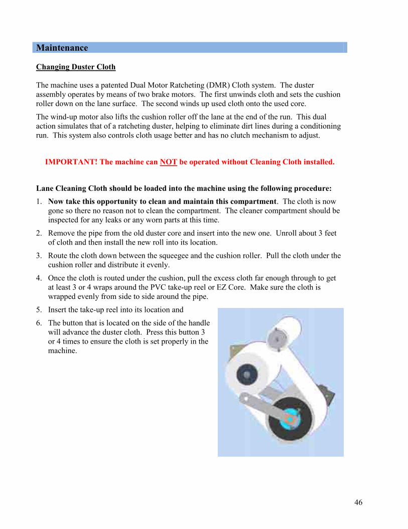
Changing Duster Cloth The machine uses a patented Dual Motor Ratcheting (DMR) Cloth system. The duster assembly operates by means of two brake motors. The first unwinds cloth and sets the cushion roller down on the lane surface. The second winds up used cloth onto the used core.
The wind-up motor also lifts the cushion roller off the lane at the end of the run. This dual action simulates that of a ratcheting duster, helping to eliminate dirt lines during a conditioning run. This system also controls cloth usage better and has no clutch mechanism to adjust.
IMPORTANT! The machine can NOT be operated without Cleaning Cloth installed.
Lane Cleaning Cloth should be loaded into the machine using the following procedure: 1. Now take this opportunity to clean and maintain this compartment. The cloth is now
gone so there no reason not to clean the compartment. The cleaner compartment should be inspected for any leaks or any worn parts at this time.
2. Remove the pipe from the old duster core and insert into the new one. Unroll about 3 feet of cloth and then install the new roll into its location.
3. Route the cloth down between the squeegee and the cushion roller. Pull the cloth under the cushion roller and distribute it evenly.
4. Once the cloth is routed under the cushion, pull the excess cloth far enough through to get at least 3 or 4 wraps around the PVC take-up reel or EZ Core. Make sure the cloth is wrapped evenly from side to side around the pipe.
5. Insert the take-up reel into its location and
6. The button that is located on the side of the handle will advance the duster cloth. Press this button 3 or 4 times to ensure the cloth is set properly in the machine.
Maintenance
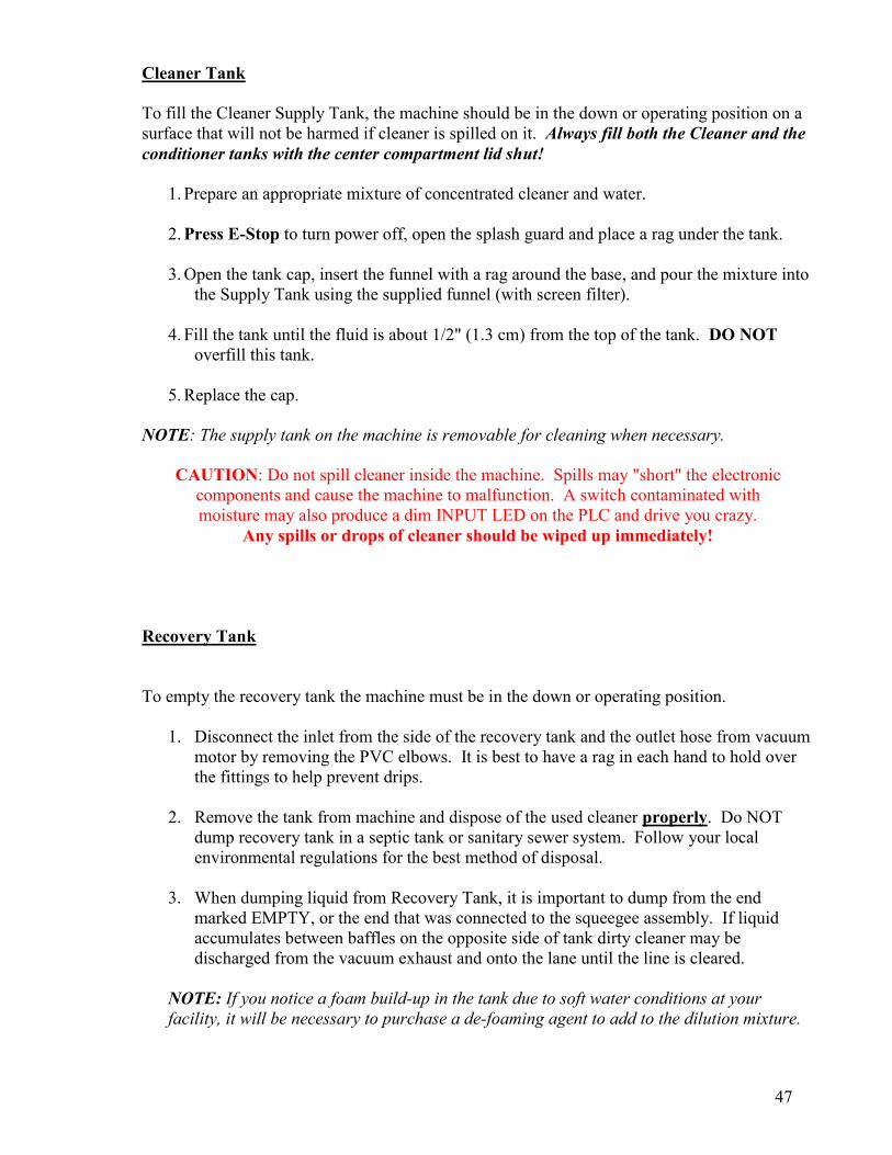
47
Cleaner Tank To fill the Cleaner Supply Tank, the machine should be in the down or operating position on a surface that will not be harmed if cleaner is spilled on it. Always fill both the Cleaner and the conditioner tanks with the center compartment lid shut!
1. Prepare an appropriate mixture of concentrated cleaner and water. 2. Press E-Stop to turn power off, open the splash guard and place a rag under the tank.
3. Open the tank cap, insert the funnel with a rag around the base, and pour the mixture into
the Supply Tank using the supplied funnel (with screen filter).
4. Fill the tank until the fluid is about 1/2" (1.3 cm) from the top of the tank. DO NOT overfill this tank.
5. Replace the cap.
NOTE: The supply tank on the machine is removable for cleaning when necessary.
CAUTION: Do not spill cleaner inside the machine. Spills may "short" the electronic components and cause the machine to malfunction. A switch contaminated with moisture may also produce a dim INPUT LED on the PLC and drive you crazy.
Any spills or drops of cleaner should be wiped up immediately! Recovery Tank To empty the recovery tank the machine must be in the down or operating position.
1. Disconnect the inlet from the side of the recovery tank and the outlet hose from vacuum motor by removing the PVC elbows. It is best to have a rag in each hand to hold over the fittings to help prevent drips.
2. Remove the tank from machine and dispose of the used cleaner properly. Do NOT
dump recovery tank in a septic tank or sanitary sewer system. Follow your local environmental regulations for the best method of disposal.
3. When dumping liquid from Recovery Tank, it is important to dump from the end
marked EMPTY, or the end that was connected to the squeegee assembly. If liquid accumulates between baffles on the opposite side of tank dirty cleaner may be discharged from the vacuum exhaust and onto the lane until the line is cleared.
NOTE: If you notice a foam build-up in the tank due to soft water conditions at your facility, it will be necessary to purchase a de-foaming agent to add to the dilution mixture.

48
4. Transporting the machine with waste in the recovery tank is one of the worst things that an operator can do. It should be strictly forbidden to allow any of your employees to do this. The vacuum will get trashed out and begin to have problems and it will also affect the battery life. Expensive PLC replacement is also possible if you are not lucky enough to clean it and have it still work (after it takes a nasty bath).
5. It is recommended that the inside of the tank be cleaned and the filter material in the tank be replaced periodically. Intervals of Maintenance will vary depending on center size so it is best to inspect the tank filter by looking though the outlet end (where the vacuum is connected) to determine how often it needs to be maintained.
NOTE: We suggest swapping recovery tank filters after each cleaning. Order a spare recovery tank filter (Part Number 158-0406).
To replace the Filter: 1. Remove the Phillips screws from the cover to access the filter.
2. Remove the filter and replace or clean it.
3. Inspect the gasket and re-fasten the cover to the recovery tank.
Squeegee Blade Replacement The squeegee blades should be flipped every 6 months and changed once a year. Poor cleaning results could occur if the trailing edge is allowed to get dull. General Maintenance
1. Squeegee should be wiped down after each use. 2. Place a drop of oil on the adjusting link end fittings and the squeegee pivots once
every 6 months. 3. Flip squeegee blades every 6 months and replace blades once a year. 4. Change filter in recovery tank once a month or when needed. 5. Check vacuum housing once a week and clean if wet with oil. 6. Check vacuum hose from squeegee head to tank for clogs at least once a year in high
lineage centers. We have seen clogs you would not believe, some look like bath tub drains with dirty, hairy clogs the size of dead rats.
7. Check the electrical end of the vacuum once a week for dirt collecting on the cover.

49
DUSTER UNWIND ERROR THE DUSTER CLOTH
DID NOT UNWIND IN TIME
DUSTER WINDUP ERROR THE DUSTER CLOTH
DID NOT WINDUP IN TIME
Please go over this section if there is any kind of problem with your cleaning system. Reviewing this before calling for Technical Support may help in correcting any problems you have. Cleaning Problems Indicated by Error Messages
Menu Out of the Program and Return machine to approach.
1. Duster cloth is empty; replace cloth.
2. One (or both) of the Duster Up Switches are stuck. Check if Input #07 has an LED light
showing on the PLC with the cloth unwound.
3. Duster did not unwind.
4. If the Duster Motor does not run, menu to the Test Output and check Output #04.
Menu Out of the Program and Return machine to approach.
1. Duster motor did not operate, or the set screw is loose and the hub is slipping on the motor
shaft.
2. Make sure the duster rolls are seated in the drive hubs and routed properly.
Troubleshooting the Cleaning System

50
SQUEEGEE UP ERROR OR THE DOWN SWITCH
IS STUCK
SQUEEGEE DOWN ERROR
OR THE UP SWITCH IS STUCK
3. Check adjustment of Wind-Up Switches and see if Input #07 has an LED light showing on
the PLC when each of the switches is actuated.
4. If the Duster Motor does not run, menu to the Test Output menu and check Output
#05.
Menu Out of the Program and Return machine to approach.
1. If Squeegee Motor runs continuously, Input #09 is not getting the signal from the Squeegee
Up Switch.
2. If Squeegee Motor does not run, menu to the Test Output screen and check Output #07.
Menu Out of the Program and Return machine to approach.
1. Machine was put on the lane before the Squeegee was lowered.
2. If Squeegee Motor runs continuously, Input #08 is not getting the signal from the Squeegee
Down Switch.
3. If Squeegee Motor does not run, menu to the Test Output screen and check Output
#07.
51
Cleaning Problems NOT Indicated by Error Messages There are a number of things that can go wrong when cleaning, but the machine will appear to operate correctly. Most of these problems can be caught before the bowlers notice them but only if the operator is paying attention. Doing a cleaner test and checking the cleaning system every day will eliminate many problems from turning into disasters.
1. Cleaner pump fails to run. a. Blown fuse. b. LY2 relay defective
2. Cleaner pump volume low.
a. Filter is clogged.
3. Machine leaves water on the lane after a test clean in various spots but cleans everywhere else.
a. Squeegee not low enough to the lane (#1 cause). b. The lane has bad depressions, possibly more than 1/100th of and inch (mostly
around screw holes). c. Squeegee has a damaged area. d. Squeegee is worn out and should have been replaced a long time ago. e. Recovery tank is not in machine.
4. Machine leaves oil streaks in various spots, but cleans everywhere else. a. Duster is not touching the lane and may not be unwinding enough cloth. b. Lane has bad depressions.
5. Machine leaves streaks that look like squeegee marks. a. Cleaner dilution is weak. b. Someone made a mistake and diluted the diluted cleaner instead of the
concentrate, making one very weak solution. c. Duster is not touching the lane and may not be unwinding enough cloth. d. You must not be using Defense-C! e. Lane has not been cleaned in months, just oiled.
6. Machine cleans only where it applies cleaner. a. The duster is definitely not touching the lane.
7. Machine drips dirty cleaner and oil off the squeegee. a. Rear squeegee blade is not clearing the tail plank. It is very important that the
rear squeegee blade clears the pin deck completely. b. The squeegee double wipe function has been turned off. c. Filter in recovery tank is plugged up. d. Vacuum hose is plugged up with hair and all kinds of nasty stuff. e. Vacuum motor is failing.

52
8. Machine pushes cleaner into gutters and excessive amounts into the pinsetter.
a. Forgot to put recovery tank in the machine (been there…done that). b. Vacuum hose has come off. c. Real nasty clog in vacuum hose after the squeegee head. d. Applying too much volume while the machine is traveling too fast.
9. Machine is leaking cleaner. a. Tank is leaking around fittings. b. Operator over-filled machine and made a mess.
10. Duster cloth hangs down on one side and sometimes touches the lane when the machine exits from of the lane.
a. Duster switches are out of adjustment; hitting the switch too soon. b. Duster plug bolt is loose from the side of the machine. c. Duster switch is broken on one side. d. Cushion Roller may be on the large side. e. Duster cloth stretched and needs to be balanced and tightened up. f. Duster motor brake is not holding (or working at all). g. New roll of duster cloth was not checked after installation. h. This machine may need a special adjustment to the program. Please call for
Technical Support at 863-734-0200.

53
KEGEL CO 2005 COPYRIGHT
VESRION xx
After pressing the ENTER key the following will appear:
From this menu prompt it is possible to change Data Memories and adjust the clock (after entering the appropriate password). It is recommended that you call Kegel Tech Support if this area needs to be accessed.
On the bottom line of the display, on the far right, is the program version in the PLC. You may be asked for this information during a technical support phone call. The operating program downloaded into this machine when it was produced is identified as 3.5.
NOTICE: The PLC program is Copyright protected. Do not attempt to make unauthorized copies of the program or download it into a machine without obtaining permission from Kegel.
This is the last menu available.
Press MENU to return to the
CROSSFIRE RUN SCREEN screen.
Copyright

54
SET LOW SPEED
?
CCHHAAPPTTEERR 44
DDrriivvee SSyysstteemm Adjustments
Drive Board Adjustments This test is very critical to the Lane Machine. If these speeds are off, then the pattern that you are using is off! The Oil Program asks for specific speeds to be used, if the speeds are not correct then you will have problems such as applying oil all the way to the foul line in reverse. To set the drive speeds you will need to Menu to the Set Low Speed screen. You will be able to check and set the LOW speed of the machine while in this screen. The factory-set speeds from low to high will toggle between the following numbers: 09-10 IPS Low Speed 19-20 IPS Second Speed 26-27 IPS High Speed If a speed adjustment is needed, locate the adjusting trimpots mounted to the frame to the left of the PLC. The speeds go in order, from left to right (low to high), and adjusted with these three trimpots. The speeds will increase when their respective trimpot are turned clockwise. When adjusting the speeds, always start with the low speed and work up to high speed. Here is how to do this step-by-step.
55
1. After you have reached the Set Low Speed screen, push the machine onto the lane. Press the Start Button on the handle one time. The machine will travel 30 feet down the lane, stop, and travel back to the foul line at low speed. You will need to walk next to the machine as it travels. The screen may toggle back and forth between speeds. Use the left-most trimpot to adjust the speed to the desired setting (the screen should flash evenly between 09-10 for the low speed). If it is too difficult to adjust the speed while the machine is moving, you can pause the machine. Press the Start Button one time to pause the machine. After you have adjusted the trimpot, press the Start Button again to have the machine resume its test run.
2. Press MENU to advance to the next speed. Follow the same procedure from STEP #1.
Adjust your second speed to 19-20, then advance to the high speed screen by pressing MENU and adjust accordingly if needed. NOTE: Just before the machine reaches the end of its travel in high speed, it will shift to low speed for the last couple of feet. This is to prevent excessive stress on the machine from a sudden stop at high speed.
3. If one of the speeds can’t be reached, an adjustment to the DC Speed Control board might
be required. Call Kegel for technical support if needed. If changes are made to the adjusting pots on this board, always go back to Speed 1 and check all the speeds again.
4. If the speeds don’t match, it will be necessary to make an adjustment to the Speed Control
board. The following steps outline this procedure.
5. Remove power to the machine.
6. Locate the Speed Control, it is attached to and directly below the speed trimpots. There
will be a trimpot on the board labeled IR, this is a compensation adjustment. This adjustment is used to equal the load and no load speeds.
7. If the machine is traveling faster than it should, then you will need to turn the trimpot
counter-clockwise. If the full-load speeds are slower, turn it clockwise. If the speed difference is not much it will be a very small adjustment.
8. Run machine on the lane and check all 3 drive speeds, repeat the step above if needed.

56
Maintenance The Drive System should be maintained, and here a are a few things that the operator should be aware of. Here are some suggestions that should be done to maintain your machine in proper working order.
1. Keep all of the bushings oiled on the drive shaft (one or two drops is plenty). Do not
allow chains to get dry but do not over-oil. There are felt washers to help hold the oil longer next to the bushings. DO NOT OVER OIL, THEY WILL DRIP FOREVER!
2. Keep the LDS shaft bushings oiled, one drop of oil every 4 to 6 months is sufficient.
3. Inspect the drive wheels for tightness and free rotation each time you clean the machine.
4. Inspect the drive chain adjustment whenever the wheels are checked or cleaned.
5. Inspect the LDS when cleaning the machine to make sure all parts are tight (it takes just
a second).
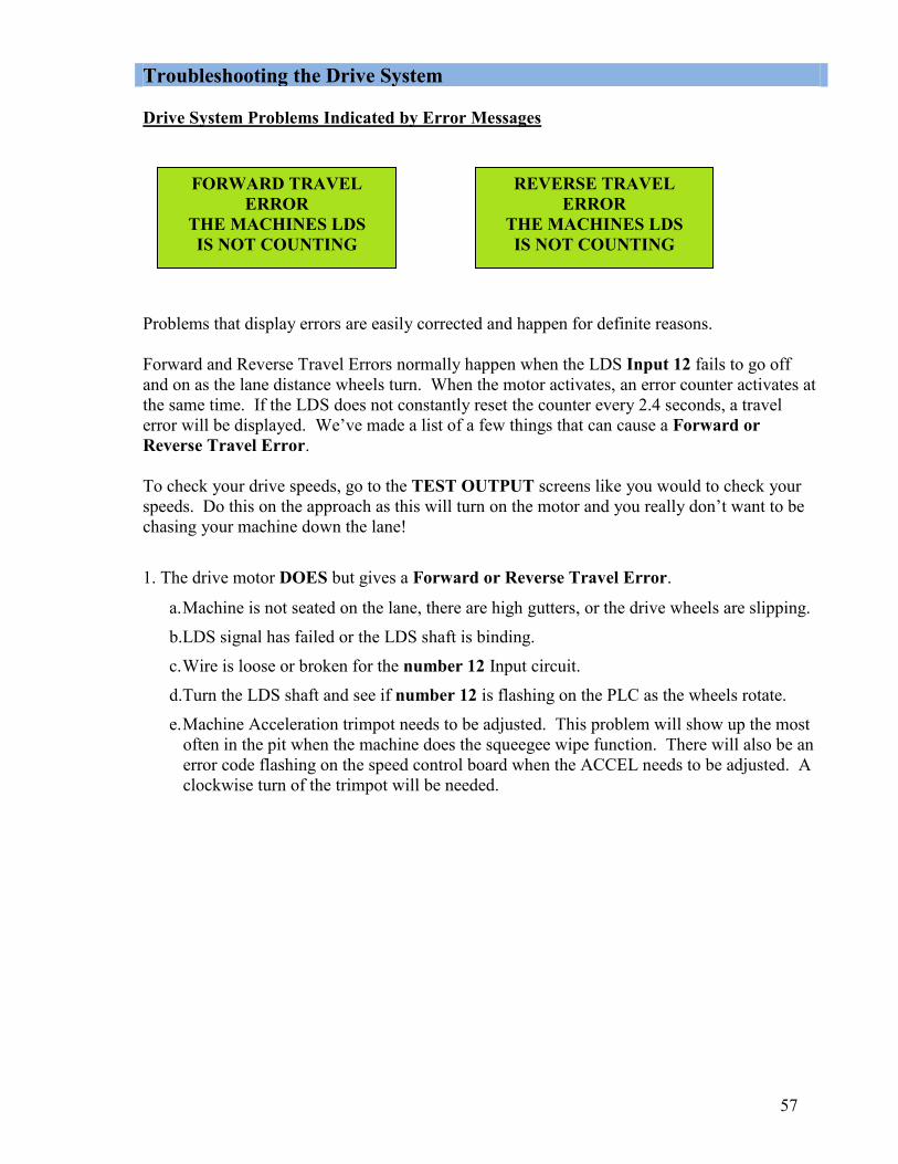
57
FORWARD TRAVEL ERROR
THE MACHINES LDS IS NOT COUNTING
REVERSE TRAVEL ERROR
THE MACHINES LDS IS NOT COUNTING
Troubleshooting the Drive System Drive System Problems Indicated by Error Messages
Problems that display errors are easily corrected and happen for definite reasons. Forward and Reverse Travel Errors normally happen when the LDS Input 12 fails to go off and on as the lane distance wheels turn. When the motor activates, an error counter activates at the same time. If the LDS does not constantly reset the counter every 2.4 seconds, a travel error will be displayed. We’ve made a list of a few things that can cause a Forward or Reverse Travel Error. To check your drive speeds, go to the TEST OUTPUT screens like you would to check your speeds. Do this on the approach as this will turn on the motor and you really don’t want to be chasing your machine down the lane!
1. The drive motor DOES but gives a Forward or Reverse Travel Error.
a. Machine is not seated on the lane, there are high gutters, or the drive wheels are slipping.
b.LDS signal has failed or the LDS shaft is binding.
c. Wire is loose or broken for the number 12 Input circuit.
d.Turn the LDS shaft and see if number 12 is flashing on the PLC as the wheels rotate. e. Machine Acceleration trimpot needs to be adjusted. This problem will show up the most
often in the pit when the machine does the squeegee wipe function. There will also be an error code flashing on the speed control board when the ACCEL needs to be adjusted. A clockwise turn of the trimpot will be needed.

58
1. Drive Motor DOES NOT run.
a. Forward Relay is loose in socket or failed.
b.Reverse Relay is loose in socket or failed.
c. One of the motor control plugs is loose or unplugged. Check speed control and drive motor plugs.
d.Blown fuse.
e. Drive Motor or Speed Control has failed.
f. Go to the proper menu and check the operation of the relays.
2. Machine drives off into pit giving a Forward Travel Error.
a. DECEL set too slow on drive board.
b. Forward Subtract needs to be increased by one or two counts.
c. Lane Distance shaft is not turning freely.
d. Lane Distance target is loose.
e. Lane Distance Proximity Sensor is too far from target.
f. Lane Distance Proximity Sensor is damaged.
g. Operator needs more training and is starting the machine too far past the foul line.
h. Tail plank is missing from pin deck. Check for missing tail planks.

59
CCHHAAPPTTEERR 55
CCoommppuutteerr aanndd CCoonnttrrooll RReellaayyss Programmable Logic Controller (PLC)
Keypad Port
Input Indicators
Output Indicators
PLC Status Indicators - See Chart
Input Terminal connector Outut Terminal
connector
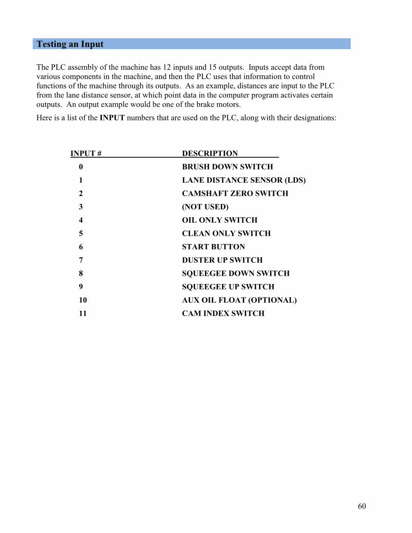
60
The PLC assembly of the machine has 12 inputs and 15 outputs. Inputs accept data from various components in the machine, and then the PLC uses that information to control functions of the machine through its outputs. As an example, distances are input to the PLC from the lane distance sensor, at which point data in the computer program activates certain outputs. An output example would be one of the brake motors.
Here is a list of the INPUT numbers that are used on the PLC, along with their designations:
INPUT # DESCRIPTION 0 BRUSH DOWN SWITCH 1 LANE DISTANCE SENSOR (LDS) 2 CAMSHAFT ZERO SWITCH 3 (NOT USED) 4 OIL ONLY SWITCH 5 CLEAN ONLY SWITCH 6 START BUTTON 7 DUSTER UP SWITCH 8 SQUEEGEE DOWN SWITCH 9 SQUEEGEE UP SWITCH 10 AUX OIL FLOAT (OPTIONAL) 11 CAM INDEX SWITCH
Testing an Input

61
Inputs and Testing Continued… Below is a wiring example of a typical input circuit using a Proximity Sensor Switch. The Proximity Switch has three wires. Blue will connect to negative, Brown to positive, and Black is the signal which connects to the appropriate PLC Input. The sensor operates when metal passes by the face. An LED light located on the sensor will indicate operation. The batteries will supply the 24 Volts. All of the machine’s Proximity Sensor Switches are wired like this; the only difference is that the wires will pass though plugs and junction blocks.

62
Inputs and Testing Continued… Testing inputs is very simple, like the flick of a light switch. To test proximity sensors pass a metal object across the face of any sensor. Lights on both the proximity sensor and PLC Input should light up. To test inputs operated by switches, depress the lever on the switch and the appropriate input should light up.
The following wiring drawings will show the simplest way a switch and proximity sensor connect to the PLC.
Below is an example of a typical input circuit using a switch. One side of the switch goes to the PLC Input and the other side of the switch goes to Negative Voltage. The PLC Input Common is supplied with Positive Voltage. The circuit is shown in the open position so there will be no input light on the PLC. The batteries will supply the 24 Volts. All of the machine switches are wired like this. The only difference is that the wires will pass though plugs and junction blocks.
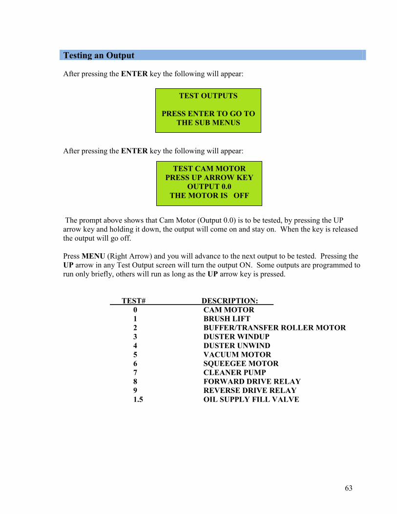
63
TEST CAM MOTOR PRESS UP ARROW KEY
OUTPUT 0.0 THE MOTOR IS OFF
TEST OUTPUTS
PRESS ENTER TO GO TO THE SUB MENUS
After pressing the ENTER key the following will appear:
After pressing the ENTER key the following will appear:
The prompt above shows that Cam Motor (Output 0.0) is to be tested, by pressing the UP arrow key and holding it down, the output will come on and stay on. When the key is released the output will go off. Press MENU (Right Arrow) and you will advance to the next output to be tested. Pressing the UP arrow in any Test Output screen will turn the output ON. Some outputs are programmed to run only briefly, others will run as long as the UP arrow key is pressed.
TEST# DESCRIPTION:
0 CAM MOTOR 1 BRUSH LIFT 2 BUFFER/TRANSFER ROLLER MOTOR
3 DUSTER WINDUP 4 DUSTER UNWIND 5 VACUUM MOTOR
6 SQUEEGEE MOTOR 7 CLEANER PUMP 8 FORWARD DRIVE RELAY 9 REVERSE DRIVE RELAY 1.5 OIL SUPPLY FILL VALVE
Testing an Output

64
Outputs and Testing continued…. Here is an example how the PLC output is wired to the isolation Control Relay. When the PLC output turns on the control relay turns on. The control relay supplies power to the motor or device to protect the PLC from heavy amp load or short circuit conditions. Only one fuse is used to protect ALL of the PLC outputs commons, so when it fails ALL outputs fail. The PLC has 6 Output Commons which, for our purposes, are all connected together by jumpers to act as one.
65
Fuses / Breakers Mounted on the control plate are several protective devices for your Crossfire DESCRIPTION AMP
PLC Power Fuse .5A PLC Common Fuse .5A Vacuum Motor Fuse 20A Squeegee Motor Fuse 3.2A Brush Lift Motor Fuse 3.2A Duster unwind Motor Fuse 3.2A Duster wind up Motor Fuse 3.2A L1 Speed Control (RD) 7.5A Cam Index Motor Fuse 2.25A Transfer Roller Motor Fuse 3.2A Cleaner Pump Fuse 3.2A Buffer Motor 10A
Do not over-amp fuses. If you can’t find the direct replacement you will cause damage to the smaller motors. In addition to fuses and breakers, the PLC program also protects the machine by “timing out” after operating motors for a pre-determined amount of time.
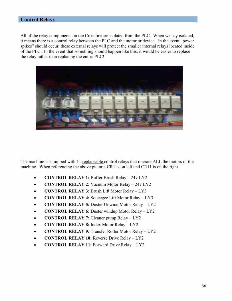
66
Control Relays All of the relay components on the Crossfire are isolated from the PLC. When we say isolated, it means there is a control relay between the PLC and the motor or device. In the event “power spikes” should occur, these external relays will protect the smaller internal relays located inside of the PLC. In the event that something should happen like this, it would be easier to replace the relay rather than replacing the entire PLC!
The machine is equipped with 11 replaceable control relays that operate ALL the motors of the machine. When referencing the above picture, CR1 is on left and CR11 is on the right.
CONTROL RELAY 1: Buffer Brush Relay – 24v LY2 CONTROL RELAY 2: Vacuum Motor Relay – 24v LY2 CONTROL RELAY 3: Brush Lift Motor Relay – LY3 CONTROL RELAY 4: Squeegee Lift Motor Relay – LY3 CONTROL RELAY 5: Duster Unwind Motor Relay – LY2 CONTROL RELAY 6: Duster windup Motor Relay – LY2 CONTROL RELAY 7: Cleaner pump Relay – LY2 CONTROL RELAY 8: Index Motor Relay – LY2 CONTROL RELAY 9: Transfer Roller Motor Relay – LY2 CONTROL RELAY 10: Reverse Drive Relay – LY2 CONTROL RELAY 11: Forward Drive Relay – LY2
67
Troubleshooting Visit www.kegel.net or call Kegel Tech Support at 863-734-0200. Lane Maintenance Central is here to help any time you call.

68
CCHHAAPPTTEERR 66
BBaatttteerryy && CChhaarrggiinngg SSyysstteemm Batteries The Battery Operated Crossfire uses two Odyssey Dry Cell batteries hooked in series to produce 25.6 volts at a full charge. These are non-spillable batteries and can be mounted on their sides. The batteries should be on charge any time the machine is not in use. Note: Do not use any battery not authorized by Kegel in this machine. Do not use flooded acid batteries in this machine.
Fuse Link The batteries are fused with a 40 amp buss fuse link between the batteries. In the case of a dead short the fuse will blow to protect the batteries and machine.
Battery Cycle Life The Odyssey Battery is capable of about 400 charge/discharge cycles to 80% depth of discharge (DOD). This is equal to doing somewhere around 32 lanes a day for over a year or a 16 lane center doing lanes twice a day and charging after each operation. The exact number of lanes that the machine can condition, will depend on the machine run time. The longer the run time, the fewer amount of lanes can be conditioned on a single charge. Battery life depends tremendously on the correct charging voltage so we can’t say enough about monitoring your charging voltage.
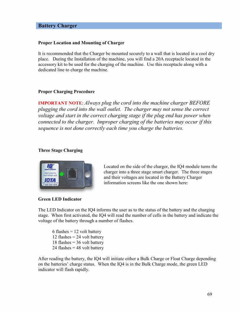
69
Battery Charger Proper Location and Mounting of Charger It is recommended that the Charger be mounted securely to a wall that is located in a cool dry place. During the Installation of the machine, you will find a 20A receptacle located in the accessory kit to be used for the charging of the machine. Use this receptacle along with a dedicated line to charge the machine. Proper Charging Procedure IMPORTANT NOTE: Always plug the cord into the machine charger BEFORE plugging the cord into the wall outlet. The charger may not sense the correct voltage and start in the correct charging stage if the plug end has power when connected to the charger. Improper charging of the batteries may occur if this sequence is not done correctly each time you charge the batteries. Three Stage Charging
Located on the side of the charger, the IQ4 module turns the charger into a three stage smart charger. The three stages and their voltages are located in the Battery Charger information screens like the one shown here:
Green LED Indicator The LED Indicator on the IQ4 informs the user as to the status of the battery and the charging stage. When first activated, the IQ4 will read the number of cells in the battery and indicate the voltage of the battery through a number of flashes.
6 flashes = 12 volt battery 12 flashes = 24 volt battery 18 flashes = 36 volt battery 24 flashes = 48 volt battery
After reading the battery, the IQ4 will initiate either a Bulk Charge or Float Charge depending on the batteries’ charge status. When the IQ4 is in the Bulk Charge mode, the green LED indicator will flash rapidly.

70
When the Bulk Charge is complete, the IQ4 begins the Absorption Charge and the LED indicator will flash at a slower even rate. When the battery charging is complete and the IQ4 begins the Float Charge, the LED will remain lit and will no longer flash. If, when first activated, the batteries are not in need of charging, the IQ4 will immediately begin the Float Charge and the LED will remain lit after it has counted the battery cells.
Constant Voltage Regulator (CVR) The CVR is located under the control plate to the left of the batteries. It maintains a constant 26.2 - 26.6 volts to the key components of the machine. It controls the drive motor, oil pump, sliding head motor, and buffer motor. The CVR is protected by a 25A internal fuse (Part Number 158-1439) which can be replaced by the operator. E-Stop The E-Stop is used to remove battery power from the machine by pressing on the big red button. The button must be rotated to resume power. The machine should always be turned off by the E-Stop during charging or maintenance. When the E-Stop is pressed while operating on the lane the machine program will be zeroed and the machine will need to be returned to the foul line and re-started.

71
CCHHAAPPTTEERR 77
TTrroouubblleesshhoooottiinngg Troubleshooting Index
The machine is equipped with Error Messages that are displayed in the event the machine malfunctions. These messages indicate the type of operational error that has occurred with the machine. Below is a list of error messages that can occur and the page number that it can be found on for troubleshooting purposes. DESCRIPTION PAGE # FORWARD TRAVEL ERROR 57 REVERSE TRAVEL ERROR 57 BRUSH DOWN ERROR 31 BRUSH UP ERROR 31 CAM INDEX ERROR 32 OIL TANK FLOAT ERROR 32 DUSTER UNWIND ERROR 49 DUSTER WIND-UP ERROR 49 SQUEEGEE UP ERROR 50 SQUEEGEE DOWN ERROR 50 PRIME PUMP ERROR TEST SCREEN ERROR In most cases, correcting the problem and resuming the machine after an Error Message is possible. In some instances, the machine will need to be returned to the foul line and then re-started.
Follow the Error Message information shown here to get several suggestions as to the reason the error occurred. Along with these suggestions there are troubleshooting suggestions.


72
CCHHAAPPTTEERR 88
MMeecchhaanniiccaall DDrraawwiinnggss Machine Descriptions and Part Numbers The following figures show major systems for the Walker and the Ion and the associated parts:
Figure 1 – Crossfire (Top View) .........................................................................................70
Figure 2 – Crossfire (Bottom View) ...................................................................................71
Figure 3 – Crossfire (Right Side) ........................................................................................72
Figure 4 – Crossfire (Left Side) ..........................................................................................73
Figure 5 – Wick and Oil Transfer Assembly ......................................................................74
Figure 5A – Wick and Oil Transfer Upgrade Assembly ....................................................75
Figure 6 – PC Relay Plate Assembly (NOT FOR BATTERY OPERATED) ....................76
Figure 7 – Vacuum Assembly.............................................................................................77
Figure 8 – Squeegee Assembly ...........................................................................................78
Figure 9 – LDS Assembly...................................................................................................79
Figure 10 – Duster Cloth Assembly....................................................................................80
Figure 11 – Cleaner Supply Assembly ...............................................................................81
Figure 12 – Brush Lift Assembly........................................................................................82

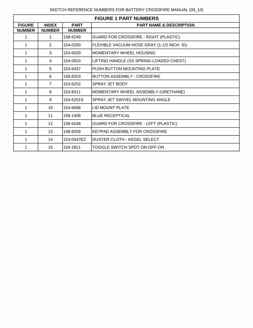
SKETCH REFERENCE NUMBERS FOR BATTERY CROSSFIRE MANUAL (09_10)
FIGURE INDEX PART PART NAME & DESCRIPTION
NUMBER NUMBER NUMBER
1 1 158-6249 GUARD FOR CROSSFIRE - RIGHT (PLASTIC)
1 2 154-0260 FLEXIBLE VACUUM HOSE GRAY (1-1/2 INCH ID)
1 3 153-6029 MOMENTARY WHEEL HOUSING
1 4 154-0810 LIFTING HANDLE (SS SPRING-LOADED CHEST)
1 5 153-6437 PUSH BUTTON MOUNTING PLATE
1 6 158-8203 BUTTON ASSEMBLY - CROSSFIRE
1 7 153-6252 SPRAY JET BODY
1 8 153-8311 MOMENTARY WHEEL ASSEMBLY (URETHANE)
1 9 153-6251S SPRAY JET SWIVEL MOUNTING ANGLE
1 10 154-6698 LID MOUNT PLATE
1 11 158-1408 BLUE RECEPTICAL
1 12 158-6248 GUARD FOR CROSSFIRE - LEFT (PLASTIC)
1 13 158-8209 KEYPAD ASSEMBLY FOR CROSSFIRE
1 14 153-0047EZ DUSTER CLOTH - KEGEL SELECT
1 15 154-1811 TOGGLE SWITCH SPDT ON-OFF-ON
FIGURE 1 PART NUMBERS


SKETCH REFERENCE NUMBERS FOR BATTERY CROSSFIRE MANUAL (09_10)
FIGURE INDEX PART PART NAME & DESCRIPTION
NUMBER NUMBER NUMBER
2 1 154-8619 PILLOWBLOCK-LANE DISTANCE (LEFT-FLANGED)
2 2 153-1408 PUSH BUTTON (RED = NORMALLY OPEN)
2 3 154-8640 FLANGED BEARING FOR BUFFER BRUSH (3/4" ROTATED)
2 4 154-6651 FRONT GUIDE ROLLER MOUNT
2 5 154-6652 GUIDE ROLLER MOUNT BLOCK
2 6 154-8007 SIDE PLATE PILLOWBLOCK FOR DRIVE SHAFT
2 7 154-6339-2133 SQUEEGEE MOUNT ANGLE (PAINTED)
2 8 154-6827 PLC RELAY MOUNT PLATE ANGLE
2 9 153-8838 CUSHION ROLLER (STEEL=44-3/8)
2 10 153-0202 COMPLETE SQUEEGEE ASSEMBLY (BLUE)
2 10 153-0202B REPLACEMENT SQUEEGEE BLADE-BLUE
2 11 154-8803 DRIVE SHAFT PILLOWBLOCK
2 12 158-6237 DRIVE SHAFT - CROSSFIRE
2 13 153-7013 URETHANE-BLEND LANE DRIVE WHEEL (4")
2 14 153-8410 LANE EDGE GUIDE ROLLER W/BUSHING (1/2")
2 15 154-8641 BUFFER BRUSH (BLUE 3-3/4" X 48)
2 16 154-8621 PILLOWBLOCK-LANE DISTANCE (RIGHT-FLANGE)
2 17 153-7002AA LANE DISTANCE COUNTER WHEEL-TREADED (2")
2 18 154-6821 LDS SHAFT
2 19 153-2740 SPRING (WICK PLATE)
2 20 154-6664 BUFFER BRUSH PULLEY SPACER
FIGURE 2 PART NUMBERS


SKETCH REFERENCE NUMBERS FOR BATTERY CROSSFIRE MANUAL (09_10)
FIGURE INDEX PART PART NAME & DESCRIPTION
NUMBER NUMBER NUMBER
3 1 158-6232 FRONT CASTER MOUNT ANGLE - CROSSFIRE
3 2 153-0812 TRANSPORT CASTER-2" HEAVY DUTY (3/8")
3 3 154-8801 SQUEEGEE ADJUSTMENT ARM
3 4 153-8403 BRAKE MOTOR ASSEMBLY (7 RPM-115V 60 Hz)
3 5 158-6254 SPRAY JET SUCTION CUP
3 6 154-0007 SPRAY TIP - STAINLESS STEEL (1501)
3 7 158-8202 HANDLE ASSEMBLY - CROSSFIRE
3 8 153-9003 SPROCKET - 40B10 (5/8")
3 9 158-8211 NOT USED
3 11 153-8841 RECOVERY TANK ASSEMBLY - MOLDED
3 12 154-0832 GARDEN HOSE FITTING CAP W/ GASKET
3 13 158-6244 ELBOW - RECOVERY TANK W/TAPPED HOLE
3 14 154-8320 PILLOWBLOCK - LANE DISTANCE SHAFT (CENTER-PLAIN)
3 15 158-0201 GARDEN HOSE FITTING 1/2 INCH BARB
3 16 158-6217 OIL FILL MOUNT - CROSSFIRE
3 17 158-6242 KEYPAD MOUNT PLATE
3 18 158-8209 KEYPAD ASSEMBLY FOR CROSSFIRE
3 19 154-6041 UHMW HANDLE STOP
3 20 153-9010 SPROCKET-25B15 (5/16")
3 21 153-0001 TRANSPORT CASTER (3" DUAL WHEEL)
3 22 154-6042 UHMW WHEEL - CORNER GUARD
3 23 154-6221 MOUNTING ANGLE - HEAVY DUTY CASTER (3 x 3.625)
3 24 158-9204 TRANSFER ROLLER DRIVE CHAIN (25P61)
3 25 154-9804 FLANGED BEARING FOR CLEANER DRIVE SHAFT
3 26 158-8402 BRAKE MOTOR ASSEMBLY (24VDC)
3 27 153-9002 SPROCKET - 40B13 (5/8")
3 28 158-9203 DRIVE CHAIN 40P39
3 29 153-2818 HHCS - 3/8-16 X 2-1/2 (GRADE 8)
3 30 158-8406 DRIVE MOTOR ASSEMBLY
FIGURE 3 PART NUMBERS
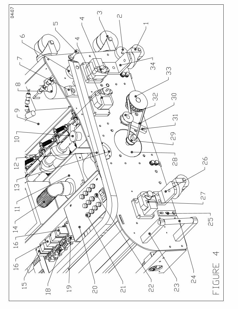
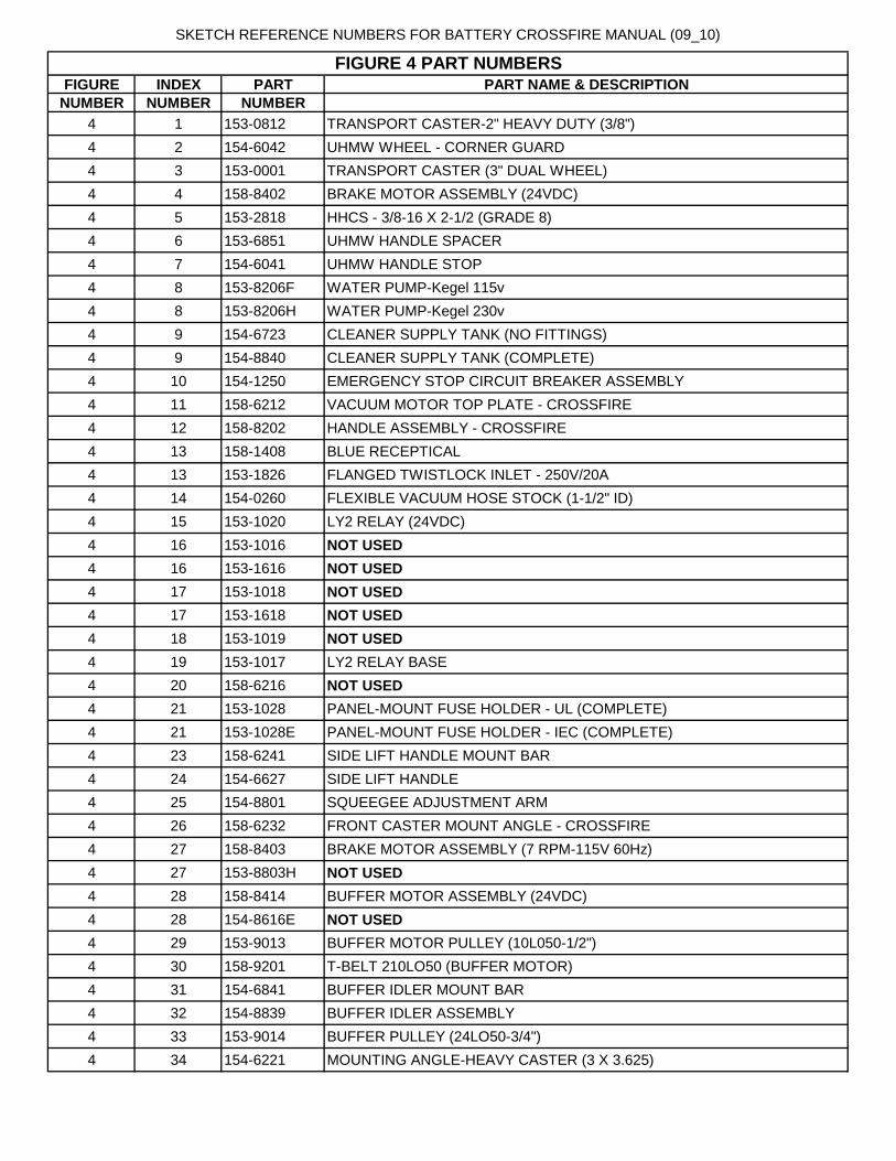
SKETCH REFERENCE NUMBERS FOR BATTERY CROSSFIRE MANUAL (09_10)
FIGURE INDEX PART PART NAME & DESCRIPTION
NUMBER NUMBER NUMBER
4 1 153-0812 TRANSPORT CASTER-2" HEAVY DUTY (3/8")4 2 154-6042 UHMW WHEEL - CORNER GUARD 4 3 153-0001 TRANSPORT CASTER (3" DUAL WHEEL)4 4 158-8402 BRAKE MOTOR ASSEMBLY (24VDC)4 5 153-2818 HHCS - 3/8-16 X 2-1/2 (GRADE 8)4 6 153-6851 UHMW HANDLE SPACER4 7 154-6041 UHMW HANDLE STOP 4 8 153-8206F WATER PUMP-Kegel 115v4 8 153-8206H WATER PUMP-Kegel 230v4 9 154-6723 CLEANER SUPPLY TANK (NO FITTINGS)4 9 154-8840 CLEANER SUPPLY TANK (COMPLETE)4 10 154-1250 EMERGENCY STOP CIRCUIT BREAKER ASSEMBLY4 11 158-6212 VACUUM MOTOR TOP PLATE - CROSSFIRE4 12 158-8202 HANDLE ASSEMBLY - CROSSFIRE4 13 158-1408 BLUE RECEPTICAL4 13 153-1826 FLANGED TWISTLOCK INLET - 250V/20A4 14 154-0260 FLEXIBLE VACUUM HOSE STOCK (1-1/2" ID)4 15 153-1020 LY2 RELAY (24VDC)4 16 153-1016 NOT USED
4 16 153-1616 NOT USED
4 17 153-1018 NOT USED
4 17 153-1618 NOT USED
4 18 153-1019 NOT USED
4 19 153-1017 LY2 RELAY BASE4 20 158-6216 NOT USED
4 21 153-1028 PANEL-MOUNT FUSE HOLDER - UL (COMPLETE)4 21 153-1028E PANEL-MOUNT FUSE HOLDER - IEC (COMPLETE)4 23 158-6241 SIDE LIFT HANDLE MOUNT BAR4 24 154-6627 SIDE LIFT HANDLE4 25 154-8801 SQUEEGEE ADJUSTMENT ARM4 26 158-6232 FRONT CASTER MOUNT ANGLE - CROSSFIRE4 27 158-8403 BRAKE MOTOR ASSEMBLY (7 RPM-115V 60Hz)4 27 153-8803H NOT USED
4 28 158-8414 BUFFER MOTOR ASSEMBLY (24VDC)4 28 154-8616E NOT USED
4 29 153-9013 BUFFER MOTOR PULLEY (10L050-1/2")4 30 158-9201 T-BELT 210LO50 (BUFFER MOTOR)4 31 154-6841 BUFFER IDLER MOUNT BAR4 32 154-8839 BUFFER IDLER ASSEMBLY4 33 153-9014 BUFFER PULLEY (24LO50-3/4")4 34 154-6221 MOUNTING ANGLE-HEAVY CASTER (3 X 3.625)
FIGURE 4 PART NUMBERS

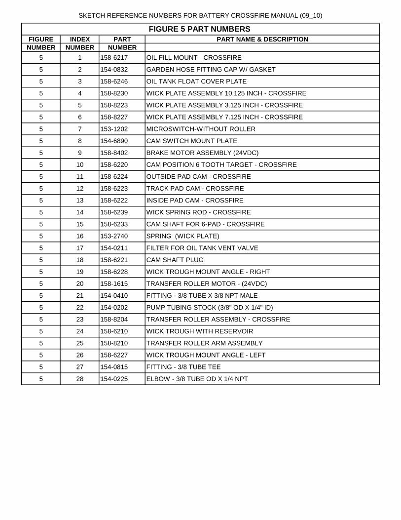
SKETCH REFERENCE NUMBERS FOR BATTERY CROSSFIRE MANUAL (09_10)
FIGURE INDEX PART PART NAME & DESCRIPTION
NUMBER NUMBER NUMBER
5 1 158-6217 OIL FILL MOUNT - CROSSFIRE
5 2 154-0832 GARDEN HOSE FITTING CAP W/ GASKET
5 3 158-6246 OIL TANK FLOAT COVER PLATE
5 4 158-8230 WICK PLATE ASSEMBLY 10.125 INCH - CROSSFIRE
5 5 158-8223 WICK PLATE ASSEMBLY 3.125 INCH - CROSSFIRE
5 6 158-8227 WICK PLATE ASSEMBLY 7.125 INCH - CROSSFIRE
5 7 153-1202 MICROSWITCH-WITHOUT ROLLER
5 8 154-6890 CAM SWITCH MOUNT PLATE
5 9 158-8402 BRAKE MOTOR ASSEMBLY (24VDC)
5 10 158-6220 CAM POSITION 6 TOOTH TARGET - CROSSFIRE
5 11 158-6224 OUTSIDE PAD CAM - CROSSFIRE
5 12 158-6223 TRACK PAD CAM - CROSSFIRE
5 13 158-6222 INSIDE PAD CAM - CROSSFIRE
5 14 158-6239 WICK SPRING ROD - CROSSFIRE
5 15 158-6233 CAM SHAFT FOR 6-PAD - CROSSFIRE
5 16 153-2740 SPRING (WICK PLATE)
5 17 154-0211 FILTER FOR OIL TANK VENT VALVE
5 18 158-6221 CAM SHAFT PLUG
5 19 158-6228 WICK TROUGH MOUNT ANGLE - RIGHT
5 20 158-1615 TRANSFER ROLLER MOTOR - (24VDC)
5 21 154-0410 FITTING - 3/8 TUBE X 3/8 NPT MALE
5 22 154-0202 PUMP TUBING STOCK (3/8" OD X 1/4" ID)
5 23 158-8204 TRANSFER ROLLER ASSEMBLY - CROSSFIRE
5 24 158-6210 WICK TROUGH WITH RESERVOIR
5 25 158-8210 TRANSFER ROLLER ARM ASSEMBLY
5 26 158-6227 WICK TROUGH MOUNT ANGLE - LEFT
5 27 154-0815 FITTING - 3/8 TUBE TEE
5 28 154-0225 ELBOW - 3/8 TUBE OD X 1/4 NPT
FIGURE 5 PART NUMBERS

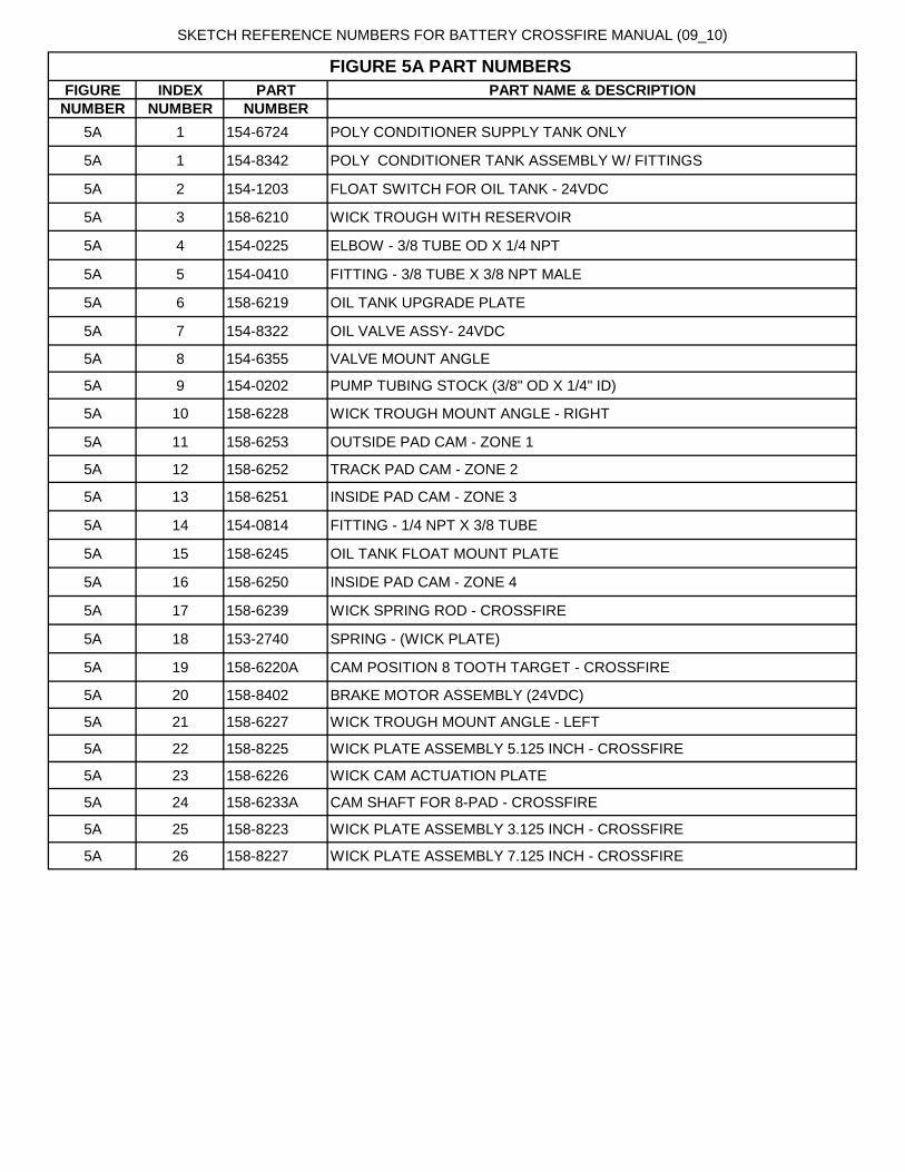
SKETCH REFERENCE NUMBERS FOR BATTERY CROSSFIRE MANUAL (09_10)
FIGURE INDEX PART PART NAME & DESCRIPTION
NUMBER NUMBER NUMBER
5A 1 154-6724 POLY CONDITIONER SUPPLY TANK ONLY
5A 1 154-8342 POLY CONDITIONER TANK ASSEMBLY W/ FITTINGS
5A 2 154-1203 FLOAT SWITCH FOR OIL TANK - 24VDC
5A 3 158-6210 WICK TROUGH WITH RESERVOIR
5A 4 154-0225 ELBOW - 3/8 TUBE OD X 1/4 NPT
5A 5 154-0410 FITTING - 3/8 TUBE X 3/8 NPT MALE
5A 6 158-6219 OIL TANK UPGRADE PLATE
5A 7 154-8322 OIL VALVE ASSY- 24VDC
5A 8 154-6355 VALVE MOUNT ANGLE
5A 9 154-0202 PUMP TUBING STOCK (3/8" OD X 1/4" ID)
5A 10 158-6228 WICK TROUGH MOUNT ANGLE - RIGHT
5A 11 158-6253 OUTSIDE PAD CAM - ZONE 1
5A 12 158-6252 TRACK PAD CAM - ZONE 2
5A 13 158-6251 INSIDE PAD CAM - ZONE 3
5A 14 154-0814 FITTING - 1/4 NPT X 3/8 TUBE
5A 15 158-6245 OIL TANK FLOAT MOUNT PLATE
5A 16 158-6250 INSIDE PAD CAM - ZONE 4
5A 17 158-6239 WICK SPRING ROD - CROSSFIRE
5A 18 153-2740 SPRING - (WICK PLATE)
5A 19 158-6220A CAM POSITION 8 TOOTH TARGET - CROSSFIRE
5A 20 158-8402 BRAKE MOTOR ASSEMBLY (24VDC)
5A 21 158-6227 WICK TROUGH MOUNT ANGLE - LEFT
5A 22 158-8225 WICK PLATE ASSEMBLY 5.125 INCH - CROSSFIRE
5A 23 158-6226 WICK CAM ACTUATION PLATE
5A 24 158-6233A CAM SHAFT FOR 8-PAD - CROSSFIRE
5A 25 158-8223 WICK PLATE ASSEMBLY 3.125 INCH - CROSSFIRE
5A 26 158-8227 WICK PLATE ASSEMBLY 7.125 INCH - CROSSFIRE
FIGURE 5A PART NUMBERS


SKETCH REFERENCE NUMBERS FOR CROSSFIRE MANUAL (04_07)
FIGURE INDEX PART PART NAME & DESCRIPTION
NUMBER NUMBER NUMBER
6 1 155-1240 PLC - TWIDO
6 2 153-1004A BUFFER MOTOR CONTACTOR (115 VOLT)
6 2 153-1604A BUFFER MOTOR CONTACTOR (230 VOLT)
6 3 153-1020 RELAY CLAMP (SOLD AS PAIR)
6 4 154-1811 TOGGLE SWITCH SPDT ON-OFF-ON
6 5 153-1028 PANEL-MOUNT FUSE HOLDER - UL (COMPLETE)
6 5 153-1028E PANEL-MOUNT FUSE HOLDER - IEC (COMPLETE)
6 6 154-1272 CIRCUIT BREAKER - DPST (10A)
6 7 153-1810 CIRCUIT BREAKER - SPST - 8 AMP (230V ONLY)
6 8 153-1809F DIN RAIL - 8-9/16 INCH
6 9 153-1017 LY2 RELAY BASE
6 10 153-1016D LY2 RELAY (24VDC)
6 11 153-1019 LY3 RELAY BASE
6 12 153-1018 LY3 RELAY (115 VOLT)
6 12 153-1618 LY3 RELAY (230 VOLT)
6 13 153-1809E DIN RAIL - 8 INCH
6 14 158-6216 PLC/RELAY MOUNT PLATE
6 15 158-0205 DECAL - FUSE PANEL CROSSFIRE - FIRST ROW
6 16 158-0205A DECAL - FUSE PANEL CROSSFIRE -SECOND ROW
6 17 158-0205B DECAL - FUSE PANEL CROSSFIRE - THIRD ROW
6 18 153-1016 LY2 RELAY (230VDC)
6 18 153-1616 LY2 RELAY (115VDC)
FIGURE 6 PART NUMBERS

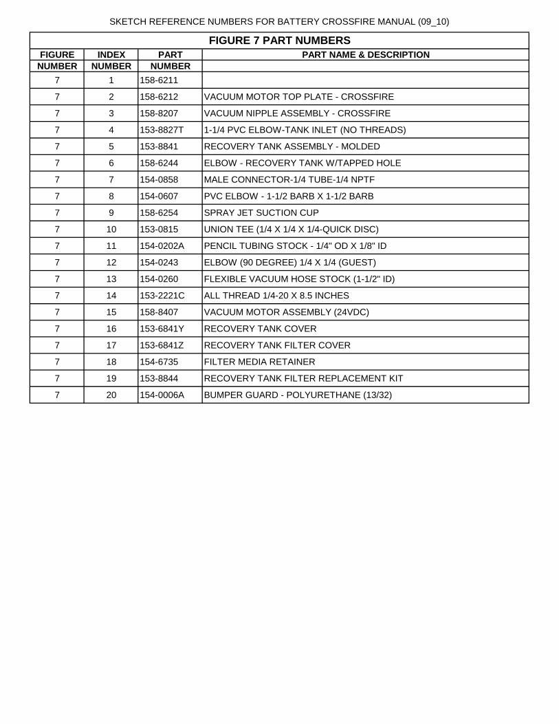
SKETCH REFERENCE NUMBERS FOR BATTERY CROSSFIRE MANUAL (09_10)
FIGURE INDEX PART PART NAME & DESCRIPTION
NUMBER NUMBER NUMBER
7 1 158-6211
7 2 158-6212 VACUUM MOTOR TOP PLATE - CROSSFIRE
7 3 158-8207 VACUUM NIPPLE ASSEMBLY - CROSSFIRE
7 4 153-8827T 1-1/4 PVC ELBOW-TANK INLET (NO THREADS)
7 5 153-8841 RECOVERY TANK ASSEMBLY - MOLDED
7 6 158-6244 ELBOW - RECOVERY TANK W/TAPPED HOLE
7 7 154-0858 MALE CONNECTOR-1/4 TUBE-1/4 NPTF
7 8 154-0607 PVC ELBOW - 1-1/2 BARB X 1-1/2 BARB
7 9 158-6254 SPRAY JET SUCTION CUP
7 10 153-0815 UNION TEE (1/4 X 1/4 X 1/4-QUICK DISC)
7 11 154-0202A PENCIL TUBING STOCK - 1/4" OD X 1/8" ID
7 12 154-0243 ELBOW (90 DEGREE) 1/4 X 1/4 (GUEST)
7 13 154-0260 FLEXIBLE VACUUM HOSE STOCK (1-1/2" ID)
7 14 153-2221C ALL THREAD 1/4-20 X 8.5 INCHES
7 15 158-8407 VACUUM MOTOR ASSEMBLY (24VDC)
7 16 153-6841Y RECOVERY TANK COVER
7 17 153-6841Z RECOVERY TANK FILTER COVER
7 18 154-6735 FILTER MEDIA RETAINER
7 19 153-8844 RECOVERY TANK FILTER REPLACEMENT KIT
7 20 154-0006A BUMPER GUARD - POLYURETHANE (13/32)
FIGURE 7 PART NUMBERS

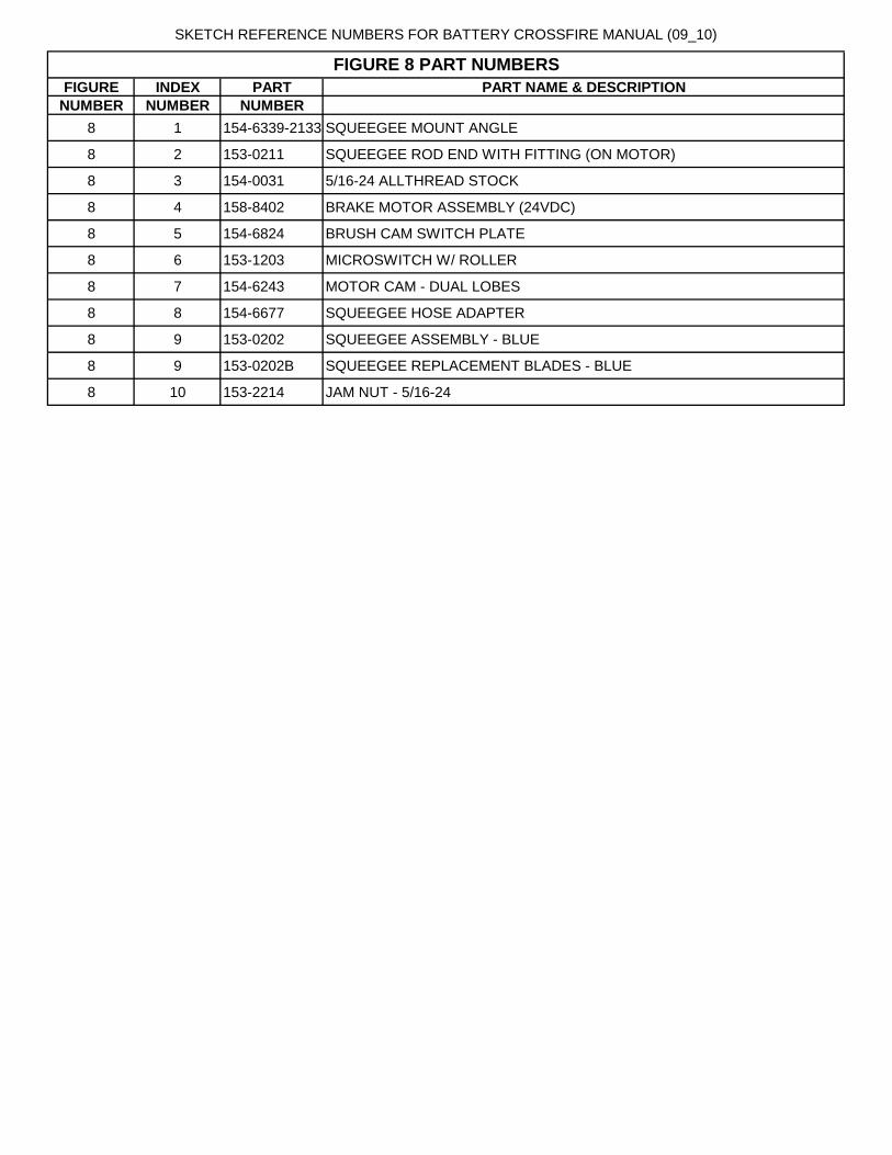
SKETCH REFERENCE NUMBERS FOR BATTERY CROSSFIRE MANUAL (09_10)
FIGURE INDEX PART PART NAME & DESCRIPTION
NUMBER NUMBER NUMBER
8 1 154-6339-2133 SQUEEGEE MOUNT ANGLE
8 2 153-0211 SQUEEGEE ROD END WITH FITTING (ON MOTOR)
8 3 154-0031 5/16-24 ALLTHREAD STOCK
8 4 158-8402 BRAKE MOTOR ASSEMBLY (24VDC)
8 5 154-6824 BRUSH CAM SWITCH PLATE
8 6 153-1203 MICROSWITCH W/ ROLLER
8 7 154-6243 MOTOR CAM - DUAL LOBES
8 8 154-6677 SQUEEGEE HOSE ADAPTER
8 9 153-0202 SQUEEGEE ASSEMBLY - BLUE
8 9 153-0202B SQUEEGEE REPLACEMENT BLADES - BLUE
8 10 153-2214 JAM NUT - 5/16-24
FIGURE 8 PART NUMBERS

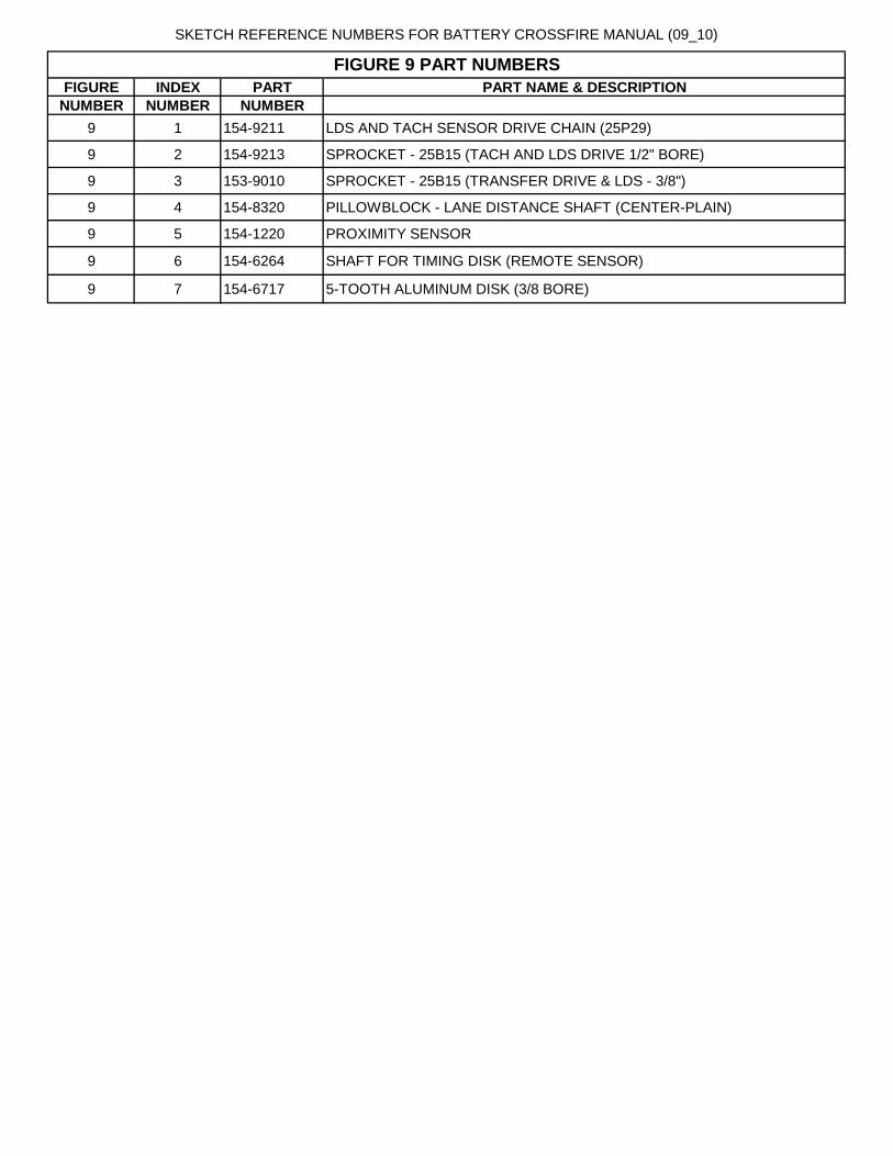
SKETCH REFERENCE NUMBERS FOR BATTERY CROSSFIRE MANUAL (09_10)
FIGURE INDEX PART PART NAME & DESCRIPTION
NUMBER NUMBER NUMBER
9 1 154-9211 LDS AND TACH SENSOR DRIVE CHAIN (25P29)
9 2 154-9213 SPROCKET - 25B15 (TACH AND LDS DRIVE 1/2" BORE)
9 3 153-9010 SPROCKET - 25B15 (TRANSFER DRIVE & LDS - 3/8")
9 4 154-8320 PILLOWBLOCK - LANE DISTANCE SHAFT (CENTER-PLAIN)
9 5 154-1220 PROXIMITY SENSOR
9 6 154-6264 SHAFT FOR TIMING DISK (REMOTE SENSOR)
9 7 154-6717 5-TOOTH ALUMINUM DISK (3/8 BORE)
FIGURE 9 PART NUMBERS


SKETCH REFERENCE NUMBERS FOR BATTERY CROSSFIRE MANUAL (09_10)
FIGURE INDEX PART PART NAME & DESCRIPTION
NUMBER NUMBER NUMBER
10 1 153-0047EZ DUSTER CLOTH
10 2 153-6850 UHMW DUSTER PLUG FOR CARDBOARD CORE
10 3 153-8420 CUSHION ROLLER PIVOT ARM ASSEMBLY
10 4 153-1202 MICROSWITCH-WITHOUT ROLLER
10 5 153-8202B DUSTER SOLID DRIVE HUB (PVC-1/4-28)
10 6 153-8824 PVC TAKE-UP REEL ASSEMBLY (44-3/4")
10 7 153-2808 SPRING - 0.42 OD X 1.25 (DUSTER PLUG)
10 8 153-8201B DUSTER DRIVE HUB ASSEMBLY (1/4-28)
10 9 153-6853 UHMW DUSTER PLUG FOR PVC TAKE-UP REEL
10 10 153-8838 CUSHION ROLLER (STEEL=44-3/8)
10 11 158-6240 DUSTER SWITCH MOUNT PLATE
FIGURE 10 PART NUMBERS
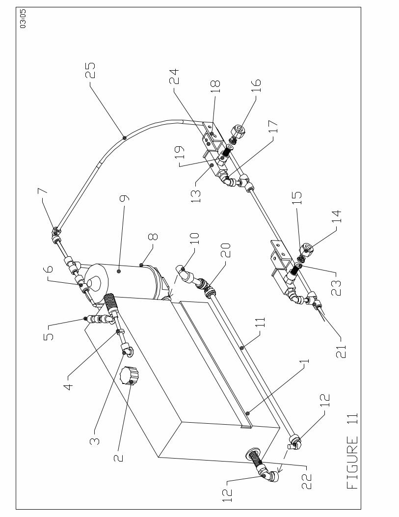
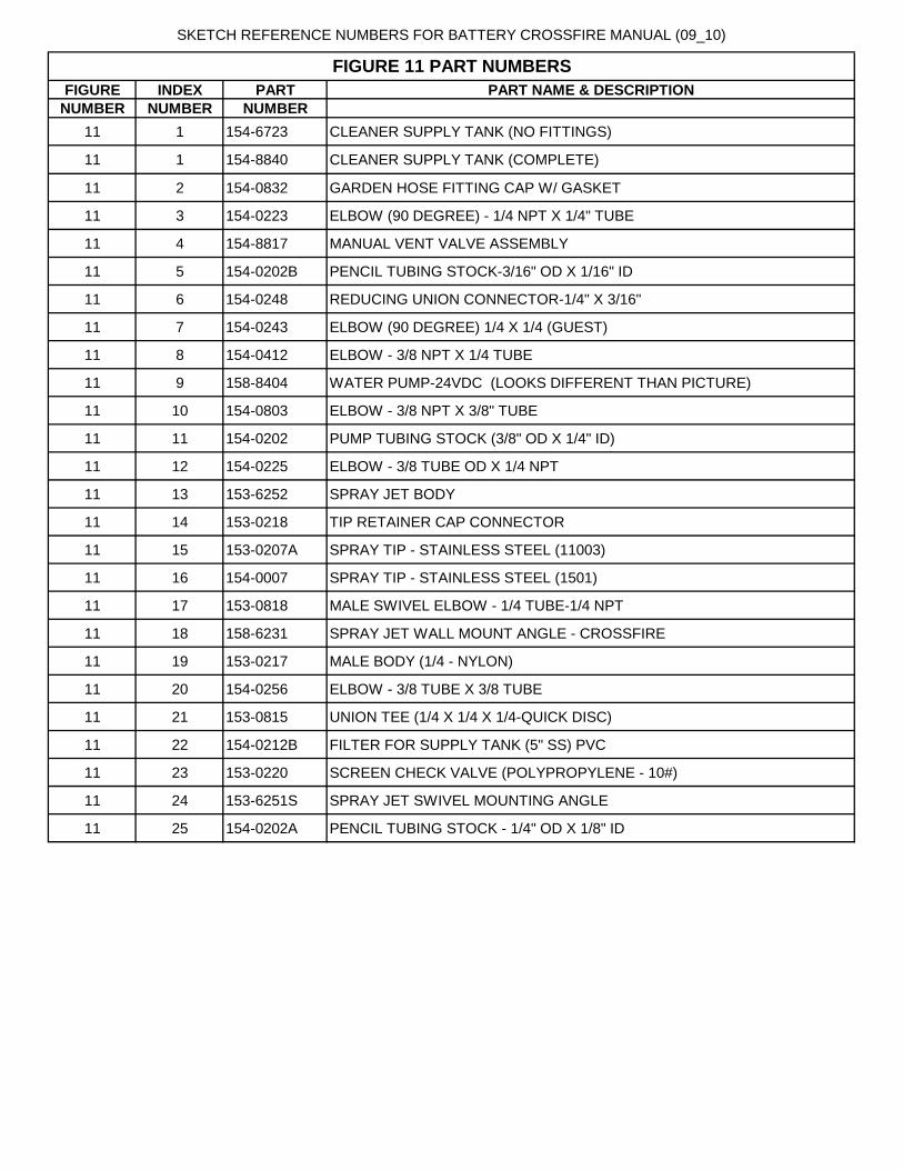
SKETCH REFERENCE NUMBERS FOR BATTERY CROSSFIRE MANUAL (09_10)
FIGURE INDEX PART PART NAME & DESCRIPTION
NUMBER NUMBER NUMBER
11 1 154-6723 CLEANER SUPPLY TANK (NO FITTINGS)
11 1 154-8840 CLEANER SUPPLY TANK (COMPLETE)
11 2 154-0832 GARDEN HOSE FITTING CAP W/ GASKET
11 3 154-0223 ELBOW (90 DEGREE) - 1/4 NPT X 1/4" TUBE
11 4 154-8817 MANUAL VENT VALVE ASSEMBLY
11 5 154-0202B PENCIL TUBING STOCK-3/16" OD X 1/16" ID
11 6 154-0248 REDUCING UNION CONNECTOR-1/4" X 3/16"
11 7 154-0243 ELBOW (90 DEGREE) 1/4 X 1/4 (GUEST)
11 8 154-0412 ELBOW - 3/8 NPT X 1/4 TUBE
11 9 158-8404 WATER PUMP-24VDC (LOOKS DIFFERENT THAN PICTURE)
11 10 154-0803 ELBOW - 3/8 NPT X 3/8" TUBE
11 11 154-0202 PUMP TUBING STOCK (3/8" OD X 1/4" ID)
11 12 154-0225 ELBOW - 3/8 TUBE OD X 1/4 NPT
11 13 153-6252 SPRAY JET BODY
11 14 153-0218 TIP RETAINER CAP CONNECTOR
11 15 153-0207A SPRAY TIP - STAINLESS STEEL (11003)
11 16 154-0007 SPRAY TIP - STAINLESS STEEL (1501)
11 17 153-0818 MALE SWIVEL ELBOW - 1/4 TUBE-1/4 NPT
11 18 158-6231 SPRAY JET WALL MOUNT ANGLE - CROSSFIRE
11 19 153-0217 MALE BODY (1/4 - NYLON)
11 20 154-0256 ELBOW - 3/8 TUBE X 3/8 TUBE
11 21 153-0815 UNION TEE (1/4 X 1/4 X 1/4-QUICK DISC)
11 22 154-0212B FILTER FOR SUPPLY TANK (5" SS) PVC
11 23 153-0220 SCREEN CHECK VALVE (POLYPROPYLENE - 10#)
11 24 153-6251S SPRAY JET SWIVEL MOUNTING ANGLE
11 25 154-0202A PENCIL TUBING STOCK - 1/4" OD X 1/8" ID
FIGURE 11 PART NUMBERS

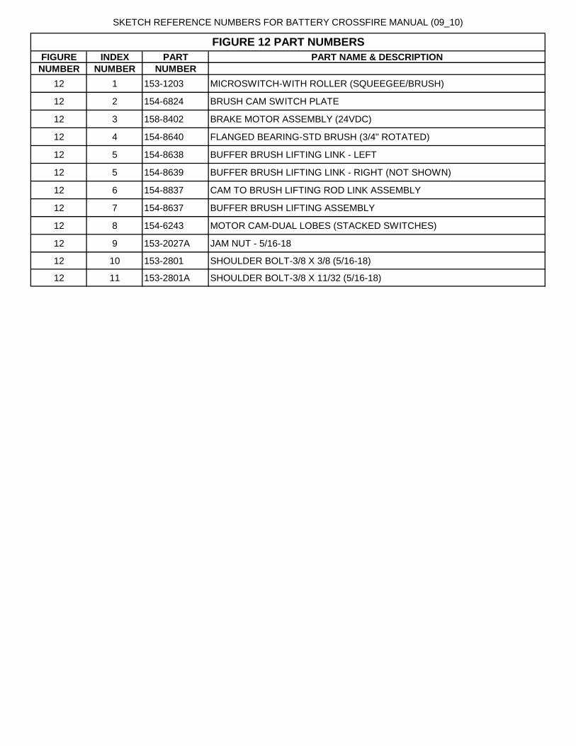
SKETCH REFERENCE NUMBERS FOR BATTERY CROSSFIRE MANUAL (09_10)
FIGURE INDEX PART PART NAME & DESCRIPTION
NUMBER NUMBER NUMBER
12 1 153-1203 MICROSWITCH-WITH ROLLER (SQUEEGEE/BRUSH)
12 2 154-6824 BRUSH CAM SWITCH PLATE
12 3 158-8402 BRAKE MOTOR ASSEMBLY (24VDC)
12 4 154-8640 FLANGED BEARING-STD BRUSH (3/4" ROTATED)
12 5 154-8638 BUFFER BRUSH LIFTING LINK - LEFT
12 5 154-8639 BUFFER BRUSH LIFTING LINK - RIGHT (NOT SHOWN)
12 6 154-8837 CAM TO BRUSH LIFTING ROD LINK ASSEMBLY
12 7 154-8637 BUFFER BRUSH LIFTING ASSEMBLY
12 8 154-6243 MOTOR CAM-DUAL LOBES (STACKED SWITCHES)
12 9 153-2027A JAM NUT - 5/16-18
12 10 153-2801 SHOULDER BOLT-3/8 X 3/8 (5/16-18)
12 11 153-2801A SHOULDER BOLT-3/8 X 11/32 (5/16-18)
FIGURE 12 PART NUMBERS

86
Crossfire Wiring Diagrams The following diagrams show wiring schematics for this lane machine. If you have any questions please call 863-734-0200 or email [email protected] . Crossfire Wiring 1..................................................................................................................84
Crossfire Wiring 2..................................................................................................................85
Crossfire Wiring 3..................................................................................................................86
Crossfire Wiring 4..................................................................................................................87
Crossfire Wiring 5..................................................................................................................88


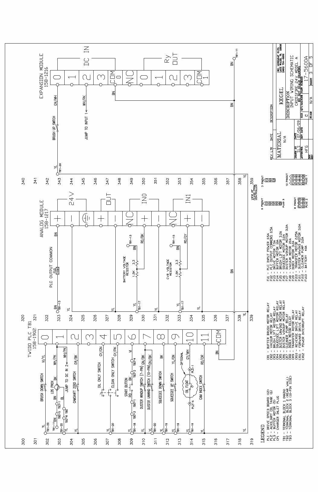
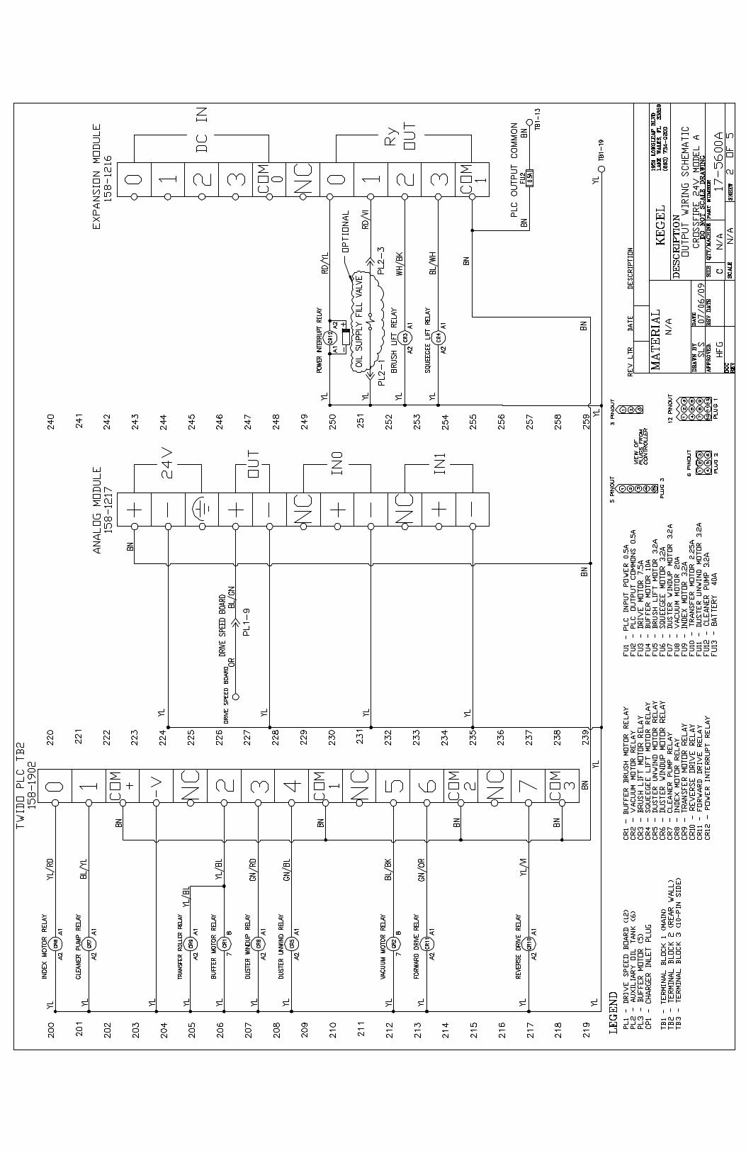

“Take care of your lane machine and it will take care of you”