model dis / das submittal record - venting … installation of this positive pressure chimney ......
TRANSCRIPT
MODELS DIS / DAS
Boiler and Engine Exhaust Chimney Systems
MODEL DIS / DASSUBMITTAL RECORD
DISSUBMIT REV. 1 03/2013
This installation manual will enable you to obtain a safe, efficient and dependable installation of this positive pressure chimney system. Please read and understand these instructions before beginning your installation.
Do not alter or modify the components of this chimney system under any circumstances. Any modification or alteration of the chimney system or approved accessories, including but not limited to the appliance it is connected to, may void the warranty, listings and approvals of this system and could result in an unsafe and potentially dangerous installation.
SUITABLE FOR POSITIVE PRESSURE VENTING APPLICATIONS WITH MAXIMUM 60” WATER COLUMN INTERNAL STATIC PRESSURE AT 1000 DEGREES F.
SAVE THESE INSTRUCTIONSFOR FUTURE REFERENCE
WARNINGSFAILURE TO FOLLOW THESE INSTALLATION INSTRUCTIONS COULD CAUSE FIRE, CARBON MONOXIDE POISONING, OR DEATH. IF YOU ARE UNSURE OF INSTALLATION REQUIREMENTS, CALL THE PHONE NUMBER LISTED ON THE BACK OF THESE INSTRUCTIONS.
A MAJOR CAUSE OF CHIMNEY RELATED FIRE IS FAILURE TO MAINTAIN REQUIRED CLEARANCES (AIR SPACES) TO COMBUSTIBLE MATERIALS. IT IS OF UTMOST IMPORTANCE THAT THIS CHIMNEY BE INSTALLED ONLY IN ACCORDANCE WITH THESE INSTRUCTIONS.
Listed to standards:UL 103 and ULC S604UL-1978 (DIS only)ULC/ORD-C959 540°C and 760°CReport # 3162834
SUBMITTAL RECORD
PREPARED FOR:
REFERENCE:
LOCATION:
CONTACT:
TELEPHONE: FAX:
EMAIL:
PREPARED BY:
MATERIAL SELECTION
INNER WALL OUTER WALL
SS 304 SS 304
SS 316 SS 316
OTHER GALVALUME
OTHER
TABLE OF CONTENTS
Introduction................................................................................. page. 2. Testing./.listing.information.................................................... page. 2General information ................................................. page 2. Maintenance.Notes................................................................. page. 2. Application.......................................................................... page. 2. Surrounding./.enclosure..................................................... page. 3. . Boiler.and.engine.exhaust........................................... page. 3. System.sizing..................................................................... page. 3. Part.numbers...................................................................... page. 3. Clearances.......................................................................... page. 3. Chimney.and.fitting.joint.assembly..................................... page. 4. Support.methods.and.height.limits..................................... page. 5. Thermal.expansion............................................................. page. 5. Chimney.weight.................................................................. page. 5. Markings.-.DIS/DAS.labels................................................. page. 6Vent lengths ........................................................... page 7. .Vent.lengths.......................................................................... page. 7. .Adjustable.vent.lengths......................................................... page. 7. .Variable.vent.lengths............................................................. page. 7. .Bellows.vent.lengths.............................................................. page. 8. .Drain.lengths......................................................................... page. 8. .Horizontal.drain.lengths........................................................ page. 8Elbows ................................................................ page 9. .3-Degree.elbows................................................................... page. 9. .15-Degree.elbows................................................................. page. 9. .30-Degree.elbows................................................................. page. 10. .45-Degree.elbows................................................................. page. 10. .90-Degree.offsets.(using.two.45-degree.elbows).................. page. 11Venting tees ........................................................... page 11. .90-Degree.tees...................................................................... page. 11. .45-Degree.tees...................................................................... page. 12. .45-Degree.tee.relief.valve...................................................... page. 12. .45-Degree.tee.y..................................................................... page. 12. .Tee.cap.................................................................................. page. 13. .Drain.tee.cap......................................................................... page. 13Venting accessories ................................................. page 13. .Locking.band......................................................................... page. 13. .Tapered.increaser.................................................................. page. 13. .Step.increaser....................................................................... page. 14. .Single.wall.adaptor................................................................ page. 14. .ANSI.flange.adaptor.............................................................. page. 14. .Flanged.hood.adaptor............................................................ page. 15. .Square.to.round.adaptor....................................................... page. 15. .DCT.to.DIS/DAS.adaptor....................................................... page. 15. .DIS/DAS.to.DCT.adaptor....................................................... page. 16. .Anchor.plate.......................................................................... page. 16. .Anchor.plate.ventilated.......................................................... page. 16. .Wall.support.......................................................................... page. 16. .Suspension.band................................................................... page. 17. .Floor.guide............................................................................ page. 17. .Wall.guide............................................................................. page. 17. .Roof.brace............................................................................. page. 18. .Guy.wire.band....................................................................... page. 18. .Firestop................................................................................. page. 18. .Wall.firestop.......................................................................... page. 18. .Flashing................................................................................. page. 19. .Storm.collar........................................................................... page. 19. .Rain.cap................................................................................ page. 19. .Finishing.cone....................................................................... page. 20. .Flip.top.................................................................................. page. 20. .Miter.cut................................................................................ page. 20. .Sealant.................................................................................. page. 20. .Relief.valve............................................................................ page. 21Warranty ................................................................page 22Product reference information ......................................page 23
INTRODUCTION
Duravent. Model. DIS. or. DAS. Chimney. are. cylindrical,. prefabricated,.modular.venting.systems.incorporating..a.unique.extended.inner.flange.designed.for.both.quick.assembly.and.pressure.sealing.capability..Model.DIS.incorporates.a.2”.of.mineral.fiber.insulation.while.DAS.is.air.insu-lated..The.circular.cross.section.and.high.quality.stainless.steel. inner.flue.construction.provide.for.a.system.with.high.strength-to-weight.ratio.and.low.friction.losses.
TESTING / LISTING INFORMATION
Duravent.model.DIS.and.DAS.venting.systems.are.listed.with.Intertek.Testing.Services.(ETL).to.UL/ULC.standards:
U.S.A.•. UL-103... -.60.in..Positive.Pressure.Chimney. -.Building.Heating.Appliance.Chimney. -.1400°F.Chimney•. UL-1978..Grease.Duct.(DIS only).CANADA•. ULC/ORD.C959. -.540°C.(1000°F). -.760°C.(1400°F)•. ULC.S604
GENERAL INFORMATION
These instructions comprise both general guidelines and special requirements for all parts in the product line. Before specifying a design or beginning an installation please carefully review these instructions.
Maintenance Notes:
Chimney Cleaning: This applies to cleaning other than standard natural gas chimney applications where minimal maintenance is necessary. Keep your chimney clean. Access should be provided for the inspec-tion and cleaning of all sections of the chimney. Have your chimney cleaned by qualified chimney sweep. It is recommended to use a nylon chimney brush of the correct size. Do not use a brush that will scratch the stainless steel interior.of.the.chimney.
APPLICATION
UL 103 Building Heating Appliance Chimney Listing:
Under.this.category,.model.DIS.and.DAS.has.been.determined.suitable.for.venting.flue.gases.at.temperatures.not.exceeding.538°C.(1000°F).under.continuous.operating.conditions.from.gas,.liquid,.oil.or.solid.fuel.fired.appliances.. .Also.complies.with.operation.(less.than.one.hour).at. temperatures. not. exceeding. 740°C. (1400°F). and. brief. operation.(maximum.10.minutes).at.temperatures.not.exceeding.906°C.(1700°F).
Building.Heating.Appliance.Chimneys.are.suitable.for.use.with.Build-ing.Heating.Appliances.and.Low.Heat.Appliances.as.described.in.the.Chimney.Selection.Chart.of.National.Fire.Protection.Association.(NFPA).Standard.NO..211.
2

UL 103 1400°F Chimney Listing:
Under.this.category,.model.DIS.and.DAS.have.been.determined.suitable.or.venting.flue.gases.at.temperatures.not.exceeding.760°C.(1400°F).under.continuous.operating.conditions.from.gas,.liquid,.oil.or.solid.fuel.fired.appliances...Also.complies.with.brief.operation.(maximum.10.minutes).at.temperatures.not.exceeding.906°C.(1700°F)...As.such,.it.is.suitable.for.use.with.ovens.and.furnaces.as.described.in.the.Chimney.Selection.Chart.of.NFPA.No..211,.in.addition.to.other.applications.
UL 103 Positive Pressure Listing:
Under.this.category,.model.DIS.and.DAS.have.been.determined.suit-able.for.use.at.a.maximum.of.60.inch.water.column.internal.pressure.
ULC-C959 540°C and 760°C Industrial Chimneys Listing:
Under.this.category,.model.DIS.and.DAS.have.been.determined.suitable.for.venting.flue.gases.at.temperatures.not.exceeding.760°C.(1400°F).under. continuous. operating. conditions. from. gas,. liquid,. oil. or. solid.fuel.fired.appliances...Also.complies.with.brief.operation.(maximum.10.minutes).at.temperatures.not.exceeding.980°C.(1800°F).
SURROUNDINGS / ENCLOSURE
Boiler and Engine Exhaust
Duravent.model.DIS.and.DAS.chimney.is.primarily.intended.to.be.used.in.fire.resistive.noncombustible.surroundings.or.installed.unenclosed..They.are.not.intended.for.use.in.one.or.two.family.residences..(CAUTION: Do not enclose this chimney in a chase or passageway of ordinary wood or other combustible material)..
Where.the.chimney.extends.through.any.zone.of.a.building.(outside.that.in.which.the.heating.appliance.connected.to.it.is.located),.it.shall.be.provided.with.an.enclosure.having.a.fire.resistance.rating.equal.to.or.greater.than.that.of.the.floor,.wall.or.roof.assemblies.through.which.it.passes..
Duravent.model.DIS.and.DAS.chimney.may.penetrate.a.combustible.floor,.wall.or.roof.using.the.appropriate.parts.and.openings.sizes...See.section.D.“Roof.&.Wall.Penetration”.for.more.details.
Where,.according.to.local.code,.no.chase.enclosure.is.necessary,.model.DIS.and.DAS.chimney.may.be.placed.adjacent.to.walls.of.combustible.construction.at.the.clearance.specified.on.each.chimney.section.and.in.the.individual.listing;.see.“CLEARANCES”...Contact.local.building.or.fire.officials.about.restrictions.and.installation.inspection.requirements.in.your.area..
SYSTEM SIZING
Complete.system.sizing.and.capacity.information.maybe.obtained.from.the.“Chimney,.Gas.Vent,.and.Fireplace.Systems”.chapter.of.the.ASHRAE.Handbook.(go.to.www.ashrae.org.for.more.information)..In.spite.of.these.general.sizing.guidelines,.it.is.most.important.that.the.heating.appliance,.engine.or.turbine.manufacturer’s.installation.instructions.are.followed..Not.following.the.equipment.manufacturer’s.instructions.may.result.in.inadequate.chimney.performance.and/or.a.violation.of. the.equipment.manufacturer’s.installation.requirements.
PART NUMBERS
These.instructions.identify.major.model.DIS.parts.by.name.and.part.number.
Example:
DIS.36”.length.with.inside.diameter.14”.made.of.ss316.inner.flue.and.ss304.outer.casing.. DIS. 14. L36. BC. Model. Dia.. Part. Material
DAS.30°.elbow.with.inside.diameter.22”.made.of.ss304.inner.flue.and.galvalume.outer.casing.. DAS. 22. E30. CE. Model. Dia.. Part. Material
DIS.wall.support.for.8”.diameter.chimney.made.of.galvalume.. DIS. 8. WS. E. Model. Dia.. Part. Material
Use only factory-supplied components. Failure to do so will void the certification and the warranty of the chimney system.
CLEARANCES
DIS
Minimum air space clearance to combustible construction to model DIS Chimney is 1”.
For non-combustible construction, maintain clearances as required for installation, access for inspection or per local code.
Inside diameter B.H.A Chimney 1400°F Chimney
Ø5” to Ø36” 1” 1”
Table 1 - Minimum air space clearance to combustible construc-tion model DIS
Inside diameter B.H.A Chimney 1400°F Chimney
Ø5” to Ø36” 4” 4”
Table 2
DAS
Minimum. air. space. clearance. to. combustible. construction. to. DAS.chimney.is.4”.
3
CHIMNEY AND FITTING JOINT ASSEMBLY
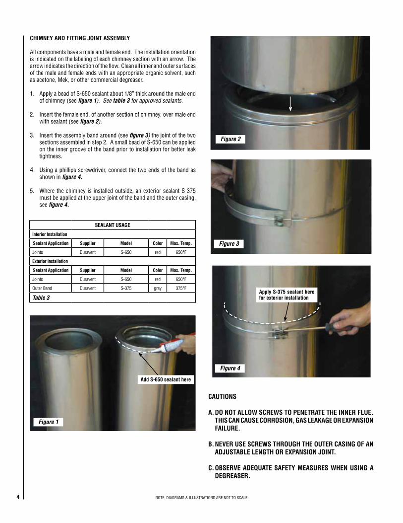
All.components.have.a.male.and.female.end...The.installation.orientation.is.indicated.on.the.labeling.of.each.chimney.section.with.an.arrow...The.arrow.indicates.the.direction.of.the.flow...Clean.all.inner.and.outer.surfaces.of.the.male.and.female.ends.with.an.appropriate.organic.solvent,.such.as.acetone,.Mek,.or.other.commercial.degreaser.
1.. .Apply.a.bead.of.S-650.sealant.about.1/8”.thick.around.the.male.end.of.chimney.(see.figure 1). See table 3 for approved sealants.
2.. .Insert.the.female.end,.of.another.section.of.chimney,.over.male.end.with.sealant.(see.figure 2).
3.. .Insert.the.assembly.band.around.(see.figure 3) the.joint.of.the.two.sections.assembled.in.step.2...A.small.bead.of.S-650.can.be.applied.on.the.inner.groove.of.the.band.prior.to.installation.for.better.leak.tightness.
4.. .Using.a.phillips.screwdriver,.connect.the.two.ends.of.the.band.as.shown.in.figure 4.
5... .Where.the.chimney. is. installed.outside,.an.exterior.sealant.S-375.must.be.applied.at.the.upper.joint.of.the.band.and.the.outer.casing,.see figure 4.
SEALANT USAGE
Interior Installation
Sealant Application Supplier Model Color Max. Temp.
Joints Duravent S-650 red 650°F
Exterior Installation
Sealant Application Supplier Model Color Max. Temp.
Joints Duravent S-650 red 650°F
Outer.Band Duravent S-375 gray 375°F
Table 3
Figure 1
Figure 2
Add S-650 sealant here
Figure 3
Figure 4
Apply S-375 sealant here for exterior installation
CAUTIONS
A. DO NOT ALLOW SCREWS TO PENETRATE THE INNER FLUE. THIS CAN CAUSE CORROSION, GAS LEAKAGE OR EXPANSION FAILURE.
B. NEVER USE SCREWS THROUGH THE OUTER CASING OF AN ADJUSTABLE LENGTH OR EXPANSION JOINT.
C. OBSERVE ADEQUATE SAFETY MEASURES WHEN USING A DEGREASER.
NOTE:.DIAGRAMS.&.ILLUSTRATIONS.ARE.NOT.TO.SCALE.4
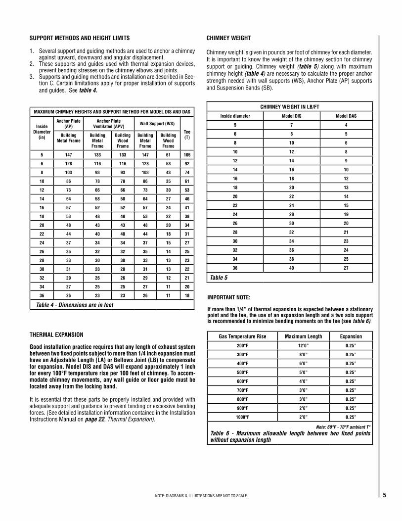
SUPPORT METHODS AND HEIGHT LIMITS
1.. .Several.support.and.guiding.methods.are.used.to.anchor.a.chimney.against.upward,.downward.and.angular.displacement.
2.. .These.supports.and.guides.used.with.thermal.expansion.devices,.prevent.bending.stresses.on.the.chimney.elbows.and.joints.
3.. Supports.and.guiding.methods.and.installation.are.described.in.Sec-tion.C..Certain.limitations.apply.for.proper.installation.of.supports.and.guides...See table 4.
MAXIMUM CHIMNEY HEIGHTS AND SUPPORT METHOD FOR MODEL DIS AND DAS
Inside Diameter
(in)
Anchor Plate (AP)
Anchor Plate Ventilated (APV)
Wall Support (WS)
Tee(T)Building
Metal FrameBuilding
Metal Frame
Building Wood Frame
Building Metal Frame
BuildingWood Frame
5 147 133 133 147 61 105
6 128 116 116 128 53 92
8 103 93 93 103 43 74
10 86 78 78 86 35 61
12 73 66 66 73 30 53
14 64 58 58 64 27 46
16 57 52 52 57 24 41
18 53 48 48 53 22 38
20 48 43 43 48 20 34
22 44 40 40 44 18 31
24 37 34 34 37 15 27
26 35 32 32 35 14 25
28 33 30 30 33 13 23
30 31 28 28 31 13 22
32 29 26 26 29 12 21
34 27 25 25 27 11 20
36 26 23 23 26 11 18
Table 4 - Dimensions are in feet
THERMAL EXPANSION
Good installation practice requires that any length of exhaust system between two fixed points subject to more than 1/4 inch expansion must have an Adjustable Length (LA) or Bellows Joint (LB) to compensate for expansion. Model DIS and DAS will expand approximately 1 inch for every 100°F temperature rise per 100 feet of chimney. To accom-modate chimney movements, any wall guide or floor guide must be located away from the locking band.
It. is.essential. that.these.parts.be.properly. installed.and.provided.with.adequate.support.and.guidance.to.prevent.binding.or.excessive.bending.forces..(See.detailed.installation.information.contained.in.the.Installation.Instructions.Manual.on.page 22,.Thermal Expansion).
CHIMNEY WEIGHT
Chimney.weight.is.given.in.pounds.per.foot.of.chimney.for.each.diameter...It.is.important.to.know.the.weight.of.the.chimney.section.for.chimney.support. or. guiding.. Chimney. weight. (table 5). along. with. maximum.chimney.height.(table 4).are.necessary.to.calculate.the.proper.anchor.strength.needed.with.wall.supports.(WS),.Anchor.Plate.(AP).supports.and.Suspension.Bands.(SB).
CHIMNEY WEIGHT IN LB/FT
Inside diameter Model DIS Model DAS
5 7 4
6 8 5
8 10 6
10 12 8
12 14 9
14 16 10
16 18 12
18 20 13
20 22 14
22 24 15
24 28 19
26 30 20
28 32 21
30 34 23
32 36 24
34 38 25
36 40 27
Table 5
IMPORTANT NOTE:
If more than 1/4” of thermal expansion is expected between a stationary point and the tee, the use of an expansion length and a two axis support is recommended to minimize bending moments on the tee (see.table 6).
Gas Temperature Rise Maximum Length Expansion
200°F 12’0” 0.25”
300°F 8’0” 0.25”
400°F 6’0” 0.25”
500°F 5’0” 0.25”
600°F 4’0” 0.25”
700°F 3’6” 0.25”
800°F 3’0” 0.25”
900°F 2’6” 0.25”
1000°F 2’0” 0.25”
Note: 60°F - 70°F ambient T°Table 6 - Maximum allowable length between two fixed points without expansion length
5NOTE:.DIAGRAMS.&.ILLUSTRATIONS.ARE.NOT.TO.SCALE.

DIS/DAS LABELS
The.labels.supplied.for.product.identification.are.shown.here.and.indicates.the.flow.of.the.flue.gases.in.the.venting.system.
Install.the.components.with.the.arrow.towards.the.termination.of.the.DIS/DAS.venting.system.
NOTE:.DIAGRAMS.&.ILLUSTRATIONS.ARE.NOT.TO.SCALE.6

NOTE:.DIAGRAMS.&.ILLUSTRATIONS.ARE.NOT.TO.SCALE. 7
VENT LENGTHS
Coding logic:
This.document.contains.a.description.of.each.of.the.parts.for.the.DIS/DAS.Durastack™.system,.as.well.as.their.respective.application.
The.following.examples.of.our.coding.system.should.make.it.easier.for.you.to.identify.or.order.them.
Material.code.definitions:.. B.=.Stainless.316. .. C.=.Stainless.304. .. E.=.Alu-Zinc.coating.(Galvalume)
Example
DIS14L36BC DAS22E30CE DIS8WSF
DIS.Model DAS.Model DIS.Model
14” Inside.Diameter
22”.Inside.Diameter
8”.Diameter
L36.36”.Length
E30.30º.Elbow
WS.Wall.Support
BC.Inner/Outer.Material
CE.Inner/Outer.Material
F.Inner/Outer
Table 7
Vent Lengths
Ø (in.) Length (in.)Effective
Length (in.)Product Code
DIS DAS
5 to 36 12 11-3/8 DISØL12 DASØL12
5 to 36 18 17-3/8 DISØL18 DASØL18
5 to 36 24 23-3/8 DISØL24 DASØL24
5 to 36 36 35-3/8 DISØL36 DASØL36
Locking band included.Flow resistance: K - 0.4 (eff. length [ft] / Ø [in]) K = 0.25 (eff. length [ft] / Ø [in]) For engine or turbine exhaustMaterials available: 304, 316, Galvalume
Adjustable Vent Lengths
Ø (in.) Effective Length (in.)
Product Code
DIS DAS
5 to 36 8 to 26 DISØLA DASØLA
Used to adjust to fit odd dimensions and to compensate for thermal expansion.Not suitable for positive pressure applications.Locking band included. Graphite packing included.Flow resistance: K - 0.4 (eff. length [ft] / Ø [in]) K = 0.25 (eff. length [ft] / Ø [in])Materials available: 304, 316, Galvalume
Figure 5 - DIS/DAS Vent Lengths
Figure 6 - DIS/DAS Adjustable Vent Lengths
Variable Vent Lengths
Ø (in.) Effective Length (in.)
Product Code
DIS DAS
5 to 36 4 to 26 DISØLV DASØLV
Used to adjust to fit odd dimensions.Not used for thermal expansion.Can be used in positive pressure applications.Locking band included. Flow resistance: K - 0.4 (eff. length [ft] / Ø [in]) K = 0.25 (eff. length [ft] / Ø [in]) For engine or turbine exhaustMaterials available: 304, 316, Galvalume
Ø
Figure 7 - DIS/DAS Variable Lengths
Effe
ctiv
e le
ngth
Effe
ctiv
e le
ngth
Air Flow
Effe
ctiv
e le
ngth

8
Bellows Vent Length
Ø (in.) Effective Length (in.)
Product Code
DIS DAS
5 to 36 8 to 26 DISØLB DASØLB
For diameters larger than 24”, the part will require special ordering and additional lead time will apply.Compression max = 3”Used to compensate for thermal expansion and to minimize vibration.Locking band included.
Flow resistance: K - 0.4 (eff. length [ft] / Ø [in]) K = 0.25 (eff. length [ft] / Ø [in]) For engine or turbine exhaustMaterials available: 304, 316, Galvalume
Figure 8 - DIS/DAS Bellows Vent Length
Effe
ctiv
e le
ngth
Drain Length
Ø (in.) Effective Length (in.)
Product Code
DIS DAS
5 to 36 17-3/8 DISØDL DASØDL
Used to drain rainwater or condensation from inner wall.Locking band included. Flow resistance: K = 0.25Materials available: 304, 316, Galvalume
Effe
ctiv
e le
ngth
1” N.P.T.Nipple
Figure 9 - DIS/DAS Drain Length
Horizontal Drain Length
Ø (in.)Effective
Length (in.)Product Code
DIS DAS
5 to 36 17-3/8 DISØHDL DASØHDL
Locking band included. Flow resistance: K = 0.4 (eff. length [ft] / Ø [in])Materials available: 304, 316, Galvalume
Figure 10 - DIS/DAS Horizontal Drain Length
1” N.P.T.Nipple
Dam
Effective length
NOTE:.DIAGRAMS.&.ILLUSTRATIONS.ARE.NOT.TO.SCALE. 9
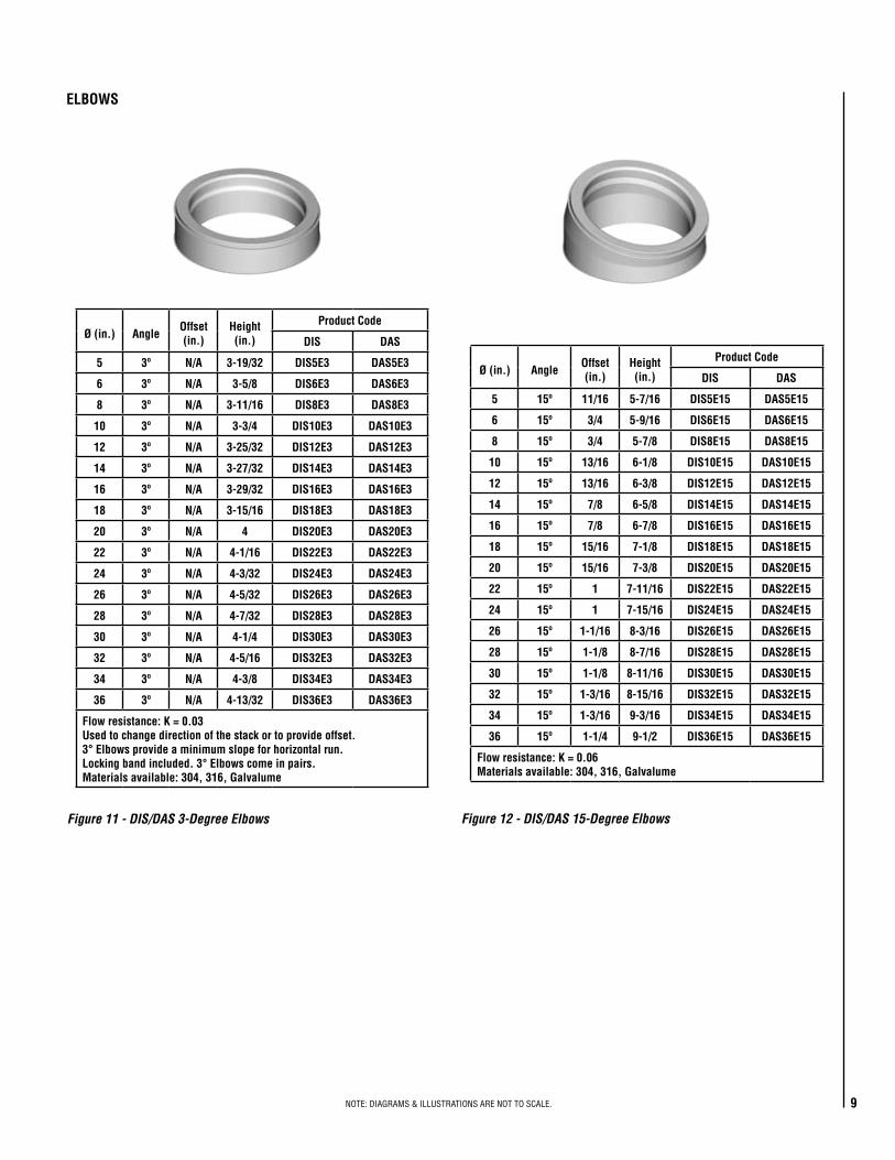
Figure 11 - DIS/DAS 3-Degree Elbows
Ø (in.) AngleOffset (in.)
Height (in.)
Product Code
DIS DAS
5 3º N/A 3-19/32 DIS5E3 DAS5E3
6 3º N/A 3-5/8 DIS6E3 DAS6E3
8 3º N/A 3-11/16 DIS8E3 DAS8E3
10 3º N/A 3-3/4 DIS10E3 DAS10E3
12 3º N/A 3-25/32 DIS12E3 DAS12E3
14 3º N/A 3-27/32 DIS14E3 DAS14E3
16 3º N/A 3-29/32 DIS16E3 DAS16E3
18 3º N/A 3-15/16 DIS18E3 DAS18E3
20 3º N/A 4 DIS20E3 DAS20E3
22 3º N/A 4-1/16 DIS22E3 DAS22E3
24 3º N/A 4-3/32 DIS24E3 DAS24E3
26 3º N/A 4-5/32 DIS26E3 DAS26E3
28 3º N/A 4-7/32 DIS28E3 DAS28E3
30 3º N/A 4-1/4 DIS30E3 DAS30E3
32 3º N/A 4-5/16 DIS32E3 DAS32E3
34 3º N/A 4-3/8 DIS34E3 DAS34E3
36 3º N/A 4-13/32 DIS36E3 DAS36E3
Flow resistance: K = 0.03Used to change direction of the stack or to provide offset. 3° Elbows provide a minimum slope for horizontal run.Locking band included. 3° Elbows come in pairs.Materials available: 304, 316, Galvalume
Ø (in.) AngleOffset (in.)
Height (in.)
Product Code
DIS DAS
5 15º 11/16 5-7/16 DIS5E15 DAS5E15
6 15º 3/4 5-9/16 DIS6E15 DAS6E15
8 15º 3/4 5-7/8 DIS8E15 DAS8E15
10 15º 13/16 6-1/8 DIS10E15 DAS10E15
12 15º 13/16 6-3/8 DIS12E15 DAS12E15
14 15º 7/8 6-5/8 DIS14E15 DAS14E15
16 15º 7/8 6-7/8 DIS16E15 DAS16E15
18 15º 15/16 7-1/8 DIS18E15 DAS18E15
20 15º 15/16 7-3/8 DIS20E15 DAS20E15
22 15º 1 7-11/16 DIS22E15 DAS22E15
24 15º 1 7-15/16 DIS24E15 DAS24E15
26 15º 1-1/16 8-3/16 DIS26E15 DAS26E15
28 15º 1-1/8 8-7/16 DIS28E15 DAS28E15
30 15º 1-1/8 8-11/16 DIS30E15 DAS30E15
32 15º 1-3/16 8-15/16 DIS32E15 DAS32E15
34 15º 1-3/16 9-3/16 DIS34E15 DAS34E15
36 15º 1-1/4 9-1/2 DIS36E15 DAS36E15
Flow resistance: K = 0.06Materials available: 304, 316, Galvalume
Figure 12 - DIS/DAS 15-Degree Elbows
ELBOWS

NOTE:.DIAGRAMS.&.ILLUSTRATIONS.ARE.NOT.TO.SCALE.10
Ø (in.) AngleOffset (in.)
Height (in.)
Product Code
DIS DAS
5 30º 1-11/16 6-5/16 DIS5E30 DAS5E30
6 30º 1-3/4 6-9/16 DIS6E30 DAS6E30
8 30º 1-7/8 7-1/16 DIS8E30 DAS8E30
10 30º 2 7-9/16 DIS10E30 DAS10E30
12 30º 2-1/8 8-1/16 DIS12E30 DAS12E30
14 30º 2-1/4 8-9/16 DIS14E30 DAS14E30
16 30º 2-3/8 9-1/16 DIS16E30 DAS16E30
18 30º 2-9/16 9-9/16 DIS18E30 DAS18E30
20 30º 2-11/16 10-1/16 DIS20E30 DAS20E30
22 30º 2-13/16 10-9/16 DIS22E30 DAS22E30
24 30º 2-15/16 11-1/16 DIS24E30 DAS24E30
26 30º 3-1/16 11-9/16 DIS26E30 DAS26E30
28 30º 3-3/16 12-1/16 DIS28E30 DAS28E30
30 30º 3-5/16 12-9/16 DIS30E30 DAS30E30
32 30º 3-1/2 13-1/16 DIS32E30 DAS32E30
34 30º 3-5/8 13-9/16 DIS34E30 DAS34E30
36 30º 3-3/4 14-1/16 DIS36E30 DAS36E30
Flow resistance: K = 0.12Materials available: 304, 316, Galvalume
Figure 13 - DIS/DAS 30-Degree Elbows
2 x Offset
2 x
Heig
ht
Offset
Heig
htAngl
e
Ø (in.) AngleOffset (in.)
Height (in.)
Product Code
DIS DAS
5 45º 2-13/16 6-15/16 DIS5E45 DAS5E45
6 45º 2-15/16 7-1/4 DIS6E45 DAS6E45
8 45º 3-1/4 8 DIS8E45 DAS8E45
10 45º 3-9/16 8-11/16 DIS10E45 DAS10E45
12 45º 3-13/16 9-3/8 DIS12E45 DAS12E45
14 45º 4-1/8 10-1/8 DIS14E45 DAS14E45
16 45º 4-7/16 10-13/16 DIS16E45 DAS16E45
18 45º 4-11/16 11-1/2 DIS18E45 DAS18E45
20 45º 5 12-13/16 DIS20E45 DAS20E45
22 45º 5-5/16 12-15/16 DIS22E45 DAS22E45
24 45º 5-5/8 13-5/8 DIS24E45 DAS24E45
26 45º 5-7/8 14-5/16 DIS26E45 DAS26E45
28 45º 6-3/16 15-1/16 DIS28E45 DAS28E45
30 45º 6-1/2 15-3/4 DIS30E45 DAS30E45
32 45º 6-3/4 16-7/16 DIS32E45 DAS32E45
34 45º 7-1/16 17-3/16 DIS34E45 DAS34E45
36 45º 7-3/8 17-7/8 DIS36E45 DAS36E45
Flow resistance: K = 0.15Materials available: 304, 316, Galvalume
Figure 14 - DIS/DAS 45 -Degree Elbows
2 x Offset
2 x
Heig
ht
Offset
Heig
htAngl
e
NOTE:.DIAGRAMS.&.ILLUSTRATIONS.ARE.NOT.TO.SCALE. 11
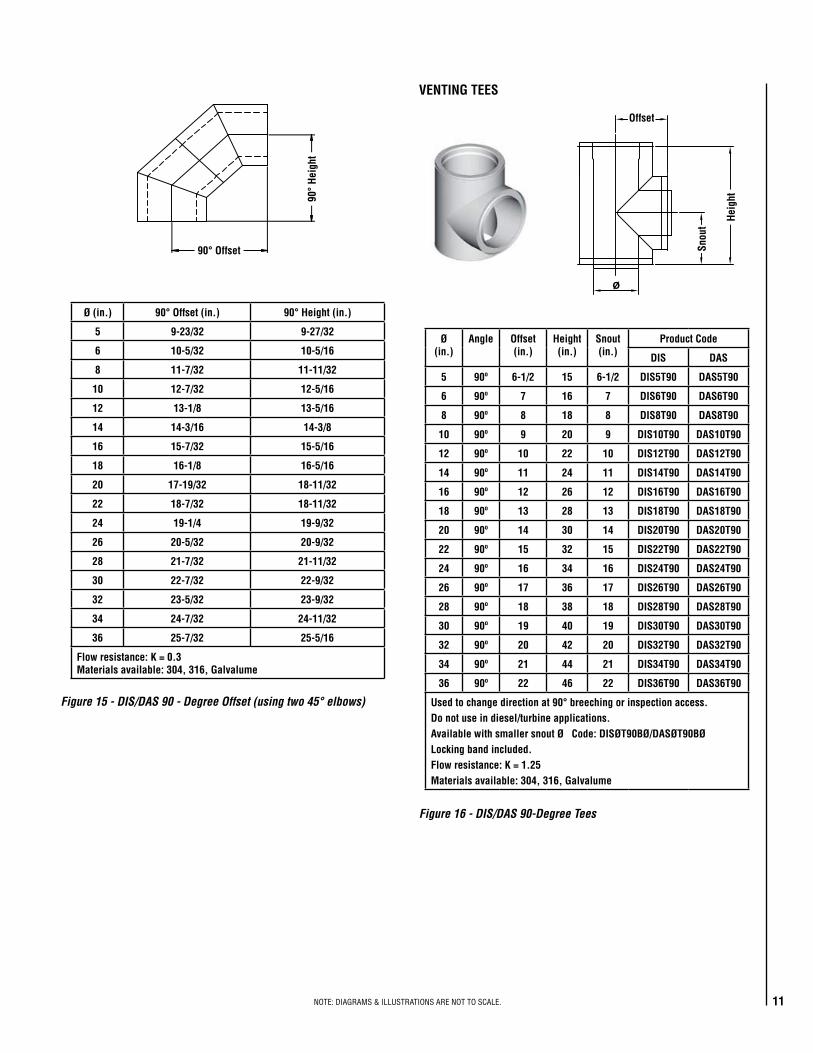
Ø (in.) 90° Offset (in.) 90° Height (in.)
5 9-23/32 9-27/32
6 10-5/32 10-5/16
8 11-7/32 11-11/32
10 12-7/32 12-5/16
12 13-1/8 13-5/16
14 14-3/16 14-3/8
16 15-7/32 15-5/16
18 16-1/8 16-5/16
20 17-19/32 18-11/32
22 18-7/32 18-11/32
24 19-1/4 19-9/32
26 20-5/32 20-9/32
28 21-7/32 21-11/32
30 22-7/32 22-9/32
32 23-5/32 23-9/32
34 24-7/32 24-11/32
36 25-7/32 25-5/16
Flow resistance: K = 0.3Materials available: 304, 316, Galvalume
Figure 15 - DIS/DAS 90 - Degree Offset (using two 45° elbows)
90° Offset
90°
Heig
ht
Ø(in.)
Angle Offset(in.)
Height (in.)
Snout (in.)
Product Code
DIS DAS
5 90º 6-1/2 15 6-1/2 DIS5T90 DAS5T90
6 90º 7 16 7 DIS6T90 DAS6T90
8 90º 8 18 8 DIS8T90 DAS8T90
10 90º 9 20 9 DIS10T90 DAS10T90
12 90º 10 22 10 DIS12T90 DAS12T90
14 90º 11 24 11 DIS14T90 DAS14T90
16 90º 12 26 12 DIS16T90 DAS16T90
18 90º 13 28 13 DIS18T90 DAS18T90
20 90º 14 30 14 DIS20T90 DAS20T90
22 90º 15 32 15 DIS22T90 DAS22T90
24 90º 16 34 16 DIS24T90 DAS24T90
26 90º 17 36 17 DIS26T90 DAS26T90
28 90º 18 38 18 DIS28T90 DAS28T90
30 90º 19 40 19 DIS30T90 DAS30T90
32 90º 20 42 20 DIS32T90 DAS32T90
34 90º 21 44 21 DIS34T90 DAS34T90
36 90º 22 46 22 DIS36T90 DAS36T90
Used to change direction at 90° breeching or inspection access. Do not use in diesel/turbine applications.Available with smaller snout Ø Code: DISØT90BØ/DASØT90BØLocking band included.Flow resistance: K = 1.25Materials available: 304, 316, Galvalume
Figure 16 - DIS/DAS 90-Degree Tees
VENTING TEES
Offset
Snou
t
Heig
ht

12
Ø(in.)
Angle Offset(in.)
Height (in.)
Snout (in.)
Product Code
DIS DAS
5 45º 10-7/16 20-5/8 4-5/16 DIS5T45 DAS5T45
6 45º 11-5/16 22-1/16 4-11/16 DIS6T45 DAS6T45
8 45º 13 24-7/8 5-3/8 DIS8T45 DAS8T45
10 45º 14-3/4 27-11/16 6-1/8 DIS10T45 DAS10T45
12 45º 16-7/16 30-9/16 6-13/16 DIS12T45 DAS12T45
14 45º 18-1/8 33-3/8 7-1/2 DIS14T45 DAS14T45
16 45º 19-7/8 36-3/16 8-1/4 DIS16T45 DAS16T45
18 45º 21-9/16 39 8-15/16 DIS18T45 DAS18T45
20 45º 23-1/4 41-7/8 9-5/8 DIS20T45 DAS20T45
22 45º 24-15/16 44-11/16 10-5/16 DIS22T45 DAS22T45
24 45º 26-11/16 47-1/2 11-1/16 DIS24T45 DAS24T45
26 45º 28-3/8 50-5/16 11-3/4 DIS26T45 DAS26T45
28 45º 30-1/16 53-3/16 12-7/16 DIS28T45 DAS28T45
30 45º 31-13/16 56 13-3/16 DIS30T45 DAS30T45
32 45º 33-1/2 58-13/16 13-7/8 DIS32T45 DAS32T45
34 45º 35-3/16 61-5/8 14-9/16 DIS34T45 DAS34T45
36 45º 36-15/16 64-1/2 15-5/16 DIS36T45 DAS36T45
Used to change direction at 45° breeching or inspection access. Available with smaller snout Ø Code: DISØT45BØ/DASØT45BØAvailable with double snout Code: DISØTD45/DASØTD45Locking band included.Flow resistance: K = 0.4Materials available: 304, 316, Galvalume
Figure 17 - DIS/DAS 45-Degree Tees
Offset
Snou
t
Heig
ht
Ø (in.)Product Code
DIS DAS
5 to 36 DISØT45RV DASØT45RV
Used in combination with the relief valve and flange adaptor.Same dimensions as 45° tee.Locking band included.Relief valve not included.Flow resistance: K = 0.4Materials available: 304, 316, Galvalume
Figure 18 - DIS/DAS 45-Degree Tee Relief Valve
Offs
et
Snout
Height
Air flow
Ø (in.) Offset (in.) Height (in.)
Product Code
DIS DAS
5 4-9/16 10-7/16 DIS5TY DAS5TY
6 4-15/16 11 DIS6TY DAS6TY
8 5-5/8 12-1/8 DIS8TY DAS8TY
10 6-5/16 13-1/4 DIS10TY DAS10TY
12 7-1/16 14-3/8 DIS12TY DAS12TY
14 7-3/4 15-1/2 DIS14TY DAS14TY
16 8-7/16 16-9/16 DIS16TY DAS16TY
18 9-3/16 17-11/16 DIS18TY DAS18TY
20 9-7/8 18-13/16 DIS20TY DAS20TY
22 10-9/16 19-15/16 DIS22TY DAS22TY
24 11-5/16 21-1/16 DIS24TY DAS24TY
26 12 22-3/16 DIS26TY DAS26TY
28 12-11/16 23-5/16 DIS28TY DAS28TY
30 13-7/16 24-7/16 DIS30TY DAS30TY
32 14-1/8 25-9/16 DIS32TY DAS32TY
34 14-13/16 26-11/16 DIS34TY DAS34TY
36 15-9/16 27-13/16 DIS36TY DAS36TY
Used to provide low-pressure drop for joining appliances.Offers same diameter on all branches.Available with smaller snout Ø Code: DISØTYØ/DASØTYØLocking band included.Flow resistance: K = 0.6Materials available: 304, 316, Galvalume
Figure 19 - DIS/DAS 45-Degree Tee YNOTE:.DIAGRAMS.&.ILLUSTRATIONS.ARE.NOT.TO.SCALE.
Air flow
Offset
Heig
ht
NOTE:.DIAGRAMS.&.ILLUSTRATIONS.ARE.NOT.TO.SCALE. 13
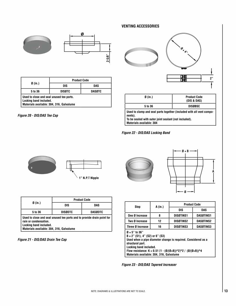
Ø (in.)Product Code
DIS DAS
5 to 36 DISØTC DASØTC
Used to close and seal unused tee ports.Locking band included.Materials available: 304, 316, Galvalume
Figure 20 - DIS/DAS Tee Cap
2-5/
8”
2”
Ø (in.)Product Code
DIS DAS
5 to 36 DISØDTC DASØDTC
Used to close and seal unused tee ports and to provide drain point for rain or condensation.Locking band included.Materials available: 304, 316, Galvalume
Figure 21 - DIS/DAS Drain Tee Cap
1” N.P.T Nipple
VENTING ACCESSORIES
Ø (in.) Product Code(DIS & DAS)
5 to 36 DISØBSC
Used to clamp and seal parts together (included with all vent compo-nents).To be sealed with outer joint sealant (not included). Materials available: 304
Figure 22 - DIS/DAS Locking Band
Ø + 4”
Step A (in.)Product Code
DIS DAS
One Ø Increase 8 DISØTINS1 DASØTINS1
Two Ø Increase 12 DISØTINS2 DASØTINS2
Three Ø Increase 16 DISØTINS3 DASØTINS3
Ø = 5” to 36”B = 2” (S1), 4” (S2) or 6” (S3)Used when a pipe diameter change is required. Considered as a structural part.Locking band included.Flow resistance: K = 0.51 [1 - (Ø/(Ø+B))^2]^2 / (Ø/(Ø+B))^4Materials available: 304, 316, Galvalume
Figure 23 - DIS/DAS Tapered Increaser
Ø
Ø + B
A

NOTE:.DIAGRAMS.&.ILLUSTRATIONS.ARE.NOT.TO.SCALE.14
Ø (in.) ØB (in.)Product Code
DIS DAS
5 to 32 8 to 36 DISØIN(ØB) DASØIN(ØB)
Used when a pipe diameter change is required in a small space.Not considered as a structural part. More restrictive than the tapered increaser.Locking band included.Flow resistance: K = [1 - (Ø/(Ø+B))^2]^2 / (Ø/(Ø+B))^4Materials available: 304, 316, Galvalume
Figure 24 - DIS/DAS Step Increaser
Ø B
5-3/
8”
5-3/
8”
Ø
Ø
ØA
Ø Int.
H
MaleMale
Female
Female
Ø (in.) ØA (in.)Product Code - Male Product Code - Female
DIS DAS DIS DAS
5 10 DIS5FA DAS5FA DIS5FFA DAS5FFA
6 11 DIS6FA DAS6FA DIS6FFA DAS6FFA
8 13-1/2 DIS8FA DAS8FA DIS8FFA DAS8FFA
10 16 DIS10FA DAS10FA DIS10FFA DAS10FFA
12 19 DIS12FA DAS12FA DIS12FFA DAS12FFA
14 21 DIS14FA DAS14FA DIS14FFA DAS14FFA
16 23 DIS16FA DAS16FA DIS16FFA DAS16FFA
18 25 DIS18FA DAS18FA DIS18FFA DAS18FFA
20 27-1/2 DIS20FA DAS20FA DIS20FFA DAS20FFA
22 29-1/2 DIS22FA DAS22FA DIS22FFA DAS22FFA
24 32 DIS24FA DAS24FA DIS24FFA DAS24FFA
26 34-1/2 DIS26FA DAS26FA DIS26FFA DAS26FFA
28 36-1/2 DIS28FA DAS28FA DIS28FFA DAS28FFA
30 38-1/2 DIS30FA DAS30FA DIS30FFA DAS30FFA
32 42 DIS32FA DAS32FA DIS32FFA DAS32FFA
34 44 DIS34FA DAS34FA DIS34FFA DAS34FFA
36 46 DIS36FA DAS36FA DIS36FFA DAS36FFA
Used for connecting a 125- or 150-lb. ANSI flange.Flange thickness = 1/4” Bolt hole pattern, bolt hole center pattern and quantity per 125-lb. ANSI.Locking band included.Outer band with insulation included.Flow resistance: K = 0.4 (eff. length [ft] / Ø [in]) K = 0.25 (eff. length [ft] / Ø [in]) For engine or turbine exhaust Materials available: 304, 316, Galvalume
Figure 26 - DIS/DAS ANSI Flange Adaptor
Ø (in.) Product Code - Male(DIS & DAS)
Product Code - Female(DIS & DAS)
5 to 36 DISØSWA DISØFSWA
Used as a non-welded attachment for appliances having an un-flanged outlet.Locking band included. Outer band with insulation included.Flow resistance: K = 0.4 (eff. length [ft] / Ø [in]) K = 0.25 (eff. length [ft] / Ø [in]) For engine or turbine exhaust Materials available: 304, 316, Galvalume
Figure 25 - DIS/DAS Single Wall Adaptor
Ø Int.
Ø Int.
Male
Dimension
Female
3-1/2”

NOTE:.DIAGRAMS.&.ILLUSTRATIONS.ARE.NOT.TO.SCALE. 15
Ø (in.) Product Code - MaleDIS & DAS
Product Code - FemaleDIS & DAS
5 to 36 DISØFHA DISØFFHA
Used on standard appliances such as kitchen hood exhausts. Flanged at the end.Locking band included. Outer band with insulation included.Flow resistance: K = 0.4 (eff. length [ft] / Ø [in]) Materials available: 304, 316, Galvalume
Figure 27 - DIS/DAS Flanged Hood Adaptor
Ø (in.) A BProduct Code
DIS DAS
5 to 36 Customizable Customizable DISØSTR(AB) DASØSTR(AB)
Locking band included.Not listed.Made to order.Materials available: 304, 316, Galvalume
Figure 28 - DIS/DAS Square to Round Adaptor
20”
Ø
Ø Int.
Ø Int.
1/2”
3-1/2”
3-1/2”A
Male
Male
FemaleFemale
B
Ø (in.)Product Code
DIS & DAS
5 to 36 DISØRCTMB
Used to connect DCT model chimney liner to DIS or DAS.Locking band included.Flow resistance: K = 0.4 (eff. length [ft] / Ø [in]) K = 0.25 (eff. length [ft] / Ø [in]) For engine or turbine exhaust Materials available: 316
Figure 29 - DCT to DIS/DAS Adaptor
5”
Ø

NOTE:.DIAGRAMS.&.ILLUSTRATIONS.ARE.NOT.TO.SCALE.16
Ø (in.) Product CodeDCT
5 to 36 DCTØRCTFB
Used to connect DIS/DAS model chimney to a DCT chimney liner. Locking band included.Flow resistance: K = 0.4 (eff. length [ft] / Ø [in]) K = 0.25 (eff. length [ft] / Ø [in]) For engine or turbine exhaust Materials available: 316
Figure 30 - DIS/DAS to DCT Adaptor
Ø
5”
Ø (in.)Product Code - Anchor Plate
DIS DAS
5 to 36 DISØAPF DASØAPF
Used for supporting the stack in vertical or horizontal runs and to provide a fixed point for thermal expansion consideration. Maintains a minimum of 1” clearance to the opening on DIS installa-tions and 4” clearance to the opening on DAS.All hardware included except connection to structure.Materials available: galvanizedMust not be in contact with combustible materials.
Ø (in.)Product Code - Anchor Plate, Heavy Duty
DIS DAS
5 to 36 DISØAPHDF DASØAPHDF
Heavy-duty steel “C” channel base – 2-1/2” x 1-1/2”
Figure 31 - DIS/DAS Anchor Plates
16
Ø + 9” DISØ + 15” DAS
Ø + 7-1/2” DISØ + 13-1/2” DAS
Ø + 4”
Ø + 11” DISØ + 15” DAS
Ø + 9-1/2” DISØ + 13-1/2” DAS
Ø + 4”
Ø (in.)Product Code
DIS DAS
5 to 36 DISØAPVF DASØAPVF
Used for supporting the stack in vertical runs in contact with com-bustible materials and to provide a fixed point for thermal expansion consideration.Maintains a minimum of 2” clearance to the opening on DIS and 4” on DAS.All hardware included except connection to structure. Materials available: galvanized
Figure 32 - DIS/DAS Anchor Plate Ventilated
Ø (in.) A (in.)Product Code
DIS DAS
5 to 36 0 to 5 DISØWSF DASØWSF
Used for supporting the stack in vertical runs in contact with combustible materials and to provide a fixed point for thermal expansion consideration.Maintains a minimum of 2-1/2” clearance to the wall on DIS and 4-1/2” on DAS and up to 7-1/2” on DIS and 9-1/2 on DAS when wall brace is extended.All hardware included except connection at wall. Materials available: galvanized
Figure 33 - DIS/DAS Wall Support
Ø
2-1/2” DIS4-1/2 DAS
A
45°
Ø +
9” D
ISØ
+ 15
” DA
S

NOTE:.DIAGRAMS.&.ILLUSTRATIONS.ARE.NOT.TO.SCALE. 17
4”
2”
Ø + 4”
Ø (in.) Product Code(DIS & DAS)
5 to 36 DISØSBE
Used for supporting and guiding the stack in horizontal runs.Allows 4” of travel for thermal expansion.Rail, trolley and band included.Flexible support strap (not included) is used to join the band and the trolley—see instruction manual for required specifications.All hardware included except connection to structure. Materials available: Galvalume
Figure 34 - DIS/DAS Suspension Band
FlexibleStrap
B
Ø + 4-1/8”
Figure 36 - DIS/DAS Wall Guide
Ø (in.) A (in.) B (in.)Product Code
DIS DAS
5 7-7/8 6-1/8 DIS5WGE DAS5WGE
6 8-9/16 6-13/16 DIS6WGE DAS6WGE
8 10 8-1/4 DIS8WGE DAS8WGE
10 11-13/32 9-21/32 DIS10WGE DAS10WGE
12 12-13/16 11-1/16 DIS12WGE DAS12WGE
14 14-7/32 12-15/32 DIS14WGE DAS14WGE
16 15-21/32 13-29/32 DIS16WGE DAS16WGE
18 17-1/16 15-5/16 DIS18WGE DAS18WGE
20 18-15/32 16-23/32 DIS20WGE DAS20WGE
22 19-7/8 18-1/8 DIS22WGE DAS22WGE
24 21-5/16 19-9/16 DIS24WGE DAS24WGE
26 22-23/32 20-31/32 DIS26WGE DAS26WGE
28 24-1/8 22-3/8 DIS28WGE DAS28WGE
30 25-17/32 23-25/32 DIS30WGE DAS30WGE
32 26-31/32 25-7/32 DIS32WGE DAS32WGE
34 28-3/8 26-5/8 DIS34WGE DAS34WGE
36 29-25/32 28-1/32 DIS36WGE DAS36WGE
Used for guiding vertical installation attached to the wall.Maintains a minimum of 1” clearance to the wall on DIS and 4” for DAS. Extension for additional clearance of 3-1/2” is included.All hardware included except connection to structure. Flexible strap (not included) can be used to add rigidity when using extension—see instruction manual for required specifications.Materials available: Galvalume
Ø + 4-1/8”
4-1/
2” D
IS /
7-1
/2”
DAS
1” D
IS /
4” D
AS
A
Ø (in.) Product Code
DIS DAS
5 to 36 DISØFGF DASØFGF
Used for guiding in vertical installation when passing through a floor or roof.Maintains a minimum of 2” clearance to the opening on DIS installa-tions and 4” clearance to the opening on DAS.All hardware included except connection to structure. Materials available: galvanized
Figure 35 - DIS/DAS Floor Guide
Ø + 9-1/2” DISØ + 13-1/2” DAS
NOTE:.DIAGRAMS.&.ILLUSTRATIONS.ARE.NOT.TO.SCALE.18
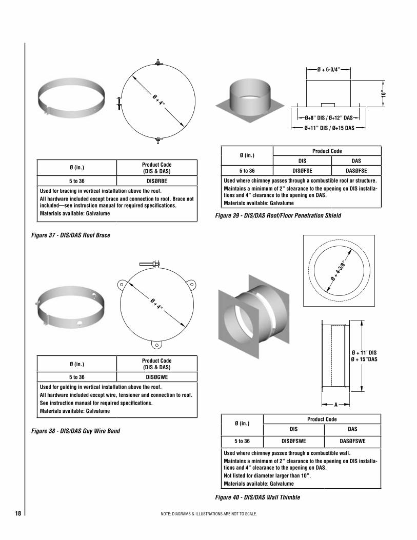
Ø + 4”
Ø (in.) Product Code(DIS & DAS)
5 to 36 DISØRBE
Used for bracing in vertical installation above the roof.All hardware included except brace and connection to roof. Brace not included—see instruction manual for required specifications. Materials available: Galvalume
Figure 37 - DIS/DAS Roof Brace
Ø (in.)Product Code(DIS & DAS)
5 to 36 DISØGWE
Used for guiding in vertical installation above the roof.All hardware included except wire, tensioner and connection to roof.See instruction manual for required specifications. Materials available: Galvalume
Figure 38 - DIS/DAS Guy Wire Band
Ø + 4”
Ø (in.)Product Code
DIS DAS
5 to 36 DISØFSE DASØFSE
Used where chimney passes through a combustible roof or structure.Maintains a minimum of 2” clearance to the opening on DIS installa-tions and 4” clearance to the opening on DAS.Materials available: Galvalume
Figure 39 - DIS/DAS Roof/Floor Penetration Shield
Ø + 6-3/4”
Ø+8” DIS / Ø+12” DAS
Ø+11” DIS / Ø+15 DAS
10”
Ø (in.)Product Code
DIS DAS
5 to 36 DISØFSWE DASØFSWE
Used where chimney passes through a combustible wall.Maintains a minimum of 2” clearance to the opening on DIS installa-tions and 4” clearance to the opening on DAS.Not listed for diameter larger than 10”. Materials available: Galvalume
Figure 40 - DIS/DAS Wall Thimble
19
Ø + 4
-3/8
”
Ø + 11”DISØ + 15”DAS
A

NOTE:.DIAGRAMS.&.ILLUSTRATIONS.ARE.NOT.TO.SCALE. 19
Ø (in.) Product Code
5 to 36 DISØF DASØF
Used in conjunction with storm collar for weatherization at the roof.Storm collar included.Materials available: Galvalume, 304
Figure 41 - DIS/DAS Flashing12
”
Ø + 22” DISØ + 26” DAS
Ø + 6”
Figure 42 - DIS/DAS Storm Collar
Ø + 4”
Ø + 7-3/16”
6-1/
4”
Ø (in.) Model Product CodeDIS & DAS
5 to 18 4 DISØCRCC
5 to 10 1 DISØRCC
12 to 18 2 DISØRCC
20 to 36 3 DISØRCC
Used to provide the greatest degree of rain protection.Model 2 is available with a bird screen, code DISØRCBC. Materials available: 304
Figure 43 - DIS/DAS Rain Cap
15”
9”
Ø
Model 1
33”
9”
Ø
Model 2
22-1
/2”
Ø
Model 3
Ø + 19”
Model 4
Ø
Ø (in.) Product CodeDIS & DAS
5 to 36 DISØSC
Used above the flashing for complete weatherization above the roof.To be sealed with outer joint sealant S-375 (not included).Materials available: Galvalume, 304

NOTE:.DIAGRAMS.&.ILLUSTRATIONS.ARE.NOT.TO.SCALE.20
Ø (in.) A (in.)Product Code
DIS & DAS
5 to 36 10 to 27 DISØFC
Used to provide the greatest draft.Requires a drain at bottom of stack.Materials available: 304, 316, Galvalume
Figure 44 - DIS/DAS Finishing Cone
Ø
A
Ø (in.) Product CodeDIS & DAS
5 to 24 DISØFTC
For engine exhaust application. Used to prevent moisture and debris from entering system. Flip top opens with internal pressure and closes when no pressure is pres-ent. Materials available: 304
Figure 45 - DIS/DAS Flip Top
Ø
5-1/
2”
Ø (in.) Product CodeDIS & DAS
5 to 36 DISØMCC
Used for horizontal engine exhaust application. Materials available: 304
Figure 46 - DIS/DAS Miter Cut
Ø
Ø + 5-1/2”
Location Max. Temp. ºF Color Product Code
Inner Joint 650 Red S-650
Outer Joint 375 Gray S-375
Red sealant is used in combination with the locking band.Gray sealant is used to protect from rain entering the system when chimney runs outside of the building and is subject to rain.
Figure 47 - DIS/DAS Sealant
Sealant Coverage
Ø Number of Joints
5 13
6 11
8 9
10 8
12 7
14 6
16-18 5
20-26 4
28-36 3
NOTE:.DIAGRAMS.&.ILLUSTRATIONS.ARE.NOT.TO.SCALE. 21
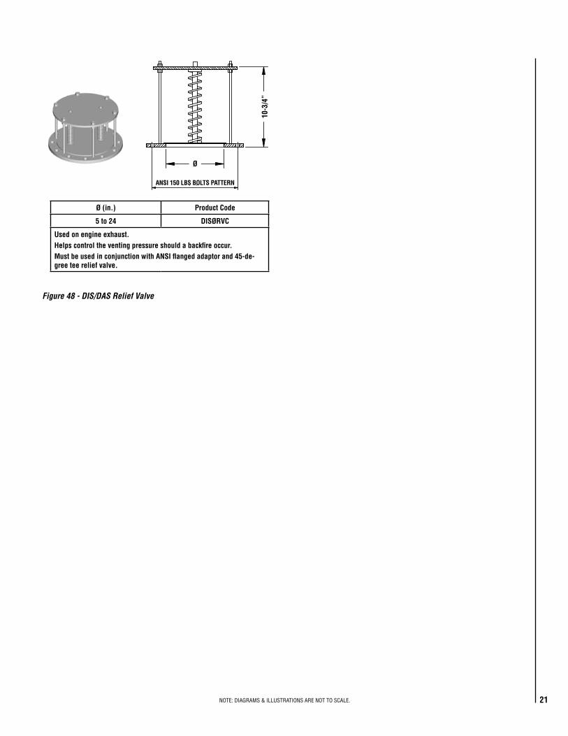
Ø (in.) Product Code
5 to 24 DISØRVC
Used on engine exhaust. Helps control the venting pressure should a backfire occur.Must be used in conjunction with ANSI flanged adaptor and 45-de-gree tee relief valve.
Figure 48 - DIS/DAS Relief Valve
Ø
10-3
/4”
ANSI 150 LBS BOLTS PATTERN

22© 2013 Duravent
F-190 REV. 0 01/2013www.duravent.com
DURAVENTDURA STACK™ – DIS
INDUSTRIAL AND COMMERCIAL CHIMNEY AND VENTING PRODUCTS1-YEAR STANDARD & 15-YEAR LIMITED WARRANTY
THE WARRANTYThis Duravent 1-Year Standard and 15-year Limited Warranty warrants your Dura Stack™ – DIS stainless steel multi-fuel double-wall chimney system (Product) to be free from defects in material and workmanship at the time of manufacture. This 1-Year Standard and 15-year Limited Warranty includes all components and fi ttings. After installation, if covered components manufactured by Duravent are found to be defective in materials or workmanship during the 1-Year Standard and 15-year Warranty period and while the Product remains at the site of the original installation, Duravent will, replace the covered components. Duravent reserves the right to replace covered components with an equivalent product and the replacement must be carried out in accordance with Duravent recommendations. If replacement is not commercially practical, Duravent will, at its option, refund the purchase price or wholesale price of the Duravent Product, whichever is applicable. Labor or freight costs to remove or replace Duravent components is not included. THERE ARE EXCLUSIONS AND LIMITATIONS to the 1-Year Standard and 15-year Limited Warranty as described herein. Duravent Grease Duct applications are covered separately (see Dura Stack – DIS Grease Duct Applications Warranty) and are not included under this warranty.
COVERAGE COMMENCEMENT DATEWarranty coverage begins on the date of shipment from Duravent.
EXCLUSIONS AND LIMITATIONSThis 1-Year Standard and 15-year Limited Warranty applies only if the Product is installed in the United States or Canada and only if used for the application for which it was designed and intended. The Product must be installed and maintained in accordance with the system design, installation and maintenance instructions for the Product and in compliance with all applicable installation and building codes and high quality, industry accepted trade practices. Any repaired or replaced product shall be warranted for the duration of time no longer than the remaining or unexpired term of the original warranty.
The 1-Year Standard Warranty is extended to the purchaser subject to the following conditions: • Generally accepted engineering practices have been followed to determine that sizing and material specifi cations are suitable for the application and environment
involved; • The components have been correctly installed in accordance with the system design and installation instructions for the Product as provided by Duravent; • Damage is not a result of burning garbage, waste oil, #6 oil or any other inappropriate or prohibited material in the appliance served by the venting system.
The Extended 15-Year Limited Warranty is extended to the purchaser subject to the following additional conditions: • The design parameters provided to Duravent by the responsible engineer at the time of design were and are accurately representative of the operating conditions; • The system sizing and design was performed or approved by Duravent ; • The boiler or engine exhaust is and has operated free of solvent or refrigerant vapors or any halogenated compound which may cause acid condensates to form
within the chimney system; • The entire chimney or exhaust system was supplied by Duravent; • Exposed galvalume and galvanized surfaces are protected with a minimum of one base coat of primer and one fi nish coat of heat resistant and corrosive resistant
paint at all times. Stainless steel surfaces do not require painting.
This warranty is non-transferable and extends to the original owner only. The Product must be purchased through an Duravent Agent/Representative and proof of purchase must be provided.
Duravent will not be responsible for: (a) damages caused by normal wear and tear, corrosion from salt air, accident, riot, fi re, fl ood or acts of God; (b) damages caused by abuse, negligence, misuse, or unauthorized alteration or repair of the Product affecting its stability or performance. (c) damages caused by failing to provide proper maintenance and service in accordance with the design, installation and maintenance instructions for the Product; (d) damages, repairs or ineffi ciency resulting from faulty installation or application of the Product.
This 1-Year Standard and 15-year Limited Warranty covers only parts as provided herein. Duravent’s entire liability is limited to the purchase price of this Product. In no case shall Duravent be responsible for materials, components or construction which are not manufactured or supplied by Duravent or for the labor necessary to install, repair or remove such materials, components or construction. All replacement or repair components will be shipped F.O.B. from the Duravent manufacturing facility.
LIMITATION ON LIABILITYIt is expressly agreed and understood that the sole obligation of Duravent and the purchaser’s exclusive remedy under this warranty, under any other warranty, expressed or implied, or in contract, tort or otherwise, shall be limited to replacement, repair, or refund, as specifi ed herein.
In no event shall Duravent be liable for any incidental or consequential damages caused by defects in the Product, whether such damage occurs or is discovered before or after replacement or repair, and whether such damage is caused by Duravent negligence.
Duravent makes no expressed warranties except as stated in this 1-Year Standard and 15-year Limited Warranty. The duration of any implied warranty is limited to the dura-tion of this expressed warranty.
No one is authorized to change this 1-Year Standard and 15-year Limited Warranty or to create for Duravent any other obligation or liability in connection with the Product. Some states and provinces do not allow the exclusion or limitation of incidental or consequential damages, so the above limitations or exclusions may not apply to you. The provisions of this 1-Year Standard and 15-year Limited Warranty are in addition to and not a modifi cation of or subtraction from any statutory warranties and other rights and remedies provided by law.
INVESTIGATION OF CLAIMS AGAINST WARRANTYDuravent reserves the right to investigate any and all claims against this 1-Year Standard and 15-year Limited Warranty and to decide, in its sole discretion, upon the method of settlement.
Duravent shall in no event be responsible for any warranty work done by a contractor that is not approved without fi rst obtaining Duravent's prior written consent.
HOW TO REGISTER A CLAIM AGAINST WARRANTYIn order for any claim under this warranty to be valid, you must contact the Duravent Agent/Representative from which you purchased the Product. If you cannot contact the Agent/Representative, then you must notify Duravent in writing. Duravent must be notifi ed of the claimed defect in writing within 90 days of the date of failure. Notices should be directed to the Duravent Warranty Department.

©.2013.DuraventDISSUBMIT REV. 1 03/2013
Duravent.reserves.the.right.to.make.changes.at.any.time,.without.notice,.in.design,.materials,.specifications,.prices..Consult.your.local.distributor.for.chimney.system.code.information.
www.duravent.com
2125.MontereyLaval,QuebecCanada,.H7L.3T6
877.Cotting.CourtVacaville,.CAUSA.95688
23
WARRANTY
These.products.have.a.limited.warranty..Please.read.the.warranty.to.be.familiar.with.its.coverage.
Retain. this. document.. File. it. with. your. other. documents. for. future.reference.
PRODUCT REFERENCE INFORMATION
Please.contact.Duravent.for.the.phone.number.of.your.nearest.Duravent.dealer.who.will.answer.your.questions.or.address.your.concerns.
Normally,.all.parts.should.be.ordered.through.your.Duravent.distributor.or.dealer..Parts.will.be.shipped.at.prevailing.prices.at.time.of.order.
When.ordering.repair.parts,.always.give.the.following.information:
1..The.model.number.of.the.chimney.system.2..The.part.number.3..The.description.of.the.part.4..The.quantity.required.5..The.installation.date.of.the.chimney.system.
If.you.encounter.any.problems.or.have.any.questions.concerning.the.installation.or.application.of.this.system,.please.contact.your.dealer.