model h 400 sa horizontal band-mitering machine operators
TRANSCRIPT

Model H 400 SA
HORIZONTAL BAND-MITERING MACHINE
OPERATORS MANUAL
PARTS LIST
Kalamazoo Machine Tool 6700 Quality Way
Portage, Michigan 49002 Phone (269) 321-8860 FAX (269) 321-8890
2
TABLE OF CONTENTS
Installation 5
Outfeed connection 8
Startup & Controls 9
Operation 12
Blade Installation 14 Angle Cutting 19
Maintenance 21
Variable Speed Drive 22
Troubleshooting 23
Blade Selection 26
Parts Illustrations, Schematics

3
SPECIFICATIONS Model H 400 SA Blade Drive Motor 4 HP, 1800 RPM, TEFC Blade Speeds 15-115 meters per minute 60-360 meet per minute Blade Size 1 1/4" wide x 13’ 2” Long Capacities @90° round/sq. 12" rectangular 10 x 15” @ 45° round 9-3/8" square 8 5/8" rectangular 7 3/4" x 9" @ 60°r round 6 5/8" square 5 7/8" rectangular 3 7/8" x 6 11/16" Work Height 37" Vise Jaw Height 6" Power Requirements 208-220-230 volts - 10 amps 440-460 volts - 5 amps 3 phase60 cycles Coolant Capacity 3.5 Gal (15 lit) Gearbox Capacity .5 gal (2.2 lit) Hydraulic Capacity 2.75 Gal (13 lit) Viscosity 46
WHEN ORDERING PARTS PLEASE STATE 1. Model Number 2. Serial Number 3. Power Supply (electrical components) 4. Quantity Required

4
SAFETY INSTRUCTIONS
TO THE OWNER OR SUPERVISOR You must remember that this machine is designed to cut metal with a sharp tool, and you are responsible to see that the machine is in top operating condition and that it is operated IN A SAFE MANNER! YOU MUST: 1. Make sure the machine is properly installed, anchored to floor, and electrical installation is proper. 2. Be sure you are familiar with all operating, safety, and applications information before operating this machine or turning it over to one of your employees. 3. See that all who operate this machine are properly trained and fully aware of all safety practices. 4. Be aware of all unsafe practices that may occur. (See operator safety precautions and applications information) 5. Insist on proper personal protective equipment and practices. 6. Maintain all factory installed safety devices and insure that these are never removed or altered or restricted in any way. 7. Insure that your operators have a safe and orderly work area, with adequate light and operating room. 8. Be certain that your machinery receives responsible and competent maintenance and that your machinery is inspected on a regular basis.
YOU ARE RESPONSIBLE SAFETY INSTRUCTIONS TO THE MACHINE OPERATOR
You must read and understand all operating, safety,
and applictions information before attempting to use this machine, including safety instructions above.
1. Use care when uncoiling and installing new bandsaw blades as the teeth are very sharp. It is advisable to wear gloves when handling saw blades. 2. Always wear proper eye protection. 3. Never operate machine unless all guards are in place. 4. Never insert hands or arms into or near cutting area while machine is running. 5. Never load or unload machine while blade is running. 6. Never wear loose clothing, long sleeves, gloves, jewelry, or any other items that may be caught. Confine long hair. 7. Adequately support stock on both sides of machine to prevent falling. 8. Never adjust guide arms when blade is running. 9. Always disconnect power at source when performing maintenance or making adjustments, other than those necessary for the normal operation of machine. 10. Keep cutting area clear of tools or other loose objects. 11. Accumulation of chips can cause problems with safety and use of this machine. Keep the machine clean. 12. Before starting a sawing cycle, be sure vise is securely clamped and machine set-up is correct. 13. Never use this machine to cut workpieces larger than the stated capacity. 14. Never use a blade other than the machine is designed for. 15. Be aware of the possible sawing problems (see APPLICATIONS section of this book) 16. CAUTION: If blade becomes jammed, immediately turn off power, loosen vise, extract workpiece from blade, and inspect blade for cracks or broken teeth.
ALWAYS OPERATE MACHINE SAFELY, USING COMMON SENSE AND ALERTNESS

5
INSTALLATION We recommend that you follow these instructions closely and report any problems to your distributor. Select an installation site that is clear of traffic and obstructions, suitable for proper machine operation and maintenance, including adequate light and clearance. The first step after uncrating your machine is to see that all items are present and that there is no apparent damage to any part of the machine. Items included are: 1. Length stop assembly 2. Assortment of wrenches 3. Knob, to be installed in the moving guide arm 4. Filler plate and mounting screws, to be fitted at swiveling point of castiron turntable. Remove the wooden blocks that support the saw frame and pendant operators console in transit, and carefully remove the machine from it’s skid, using the slots provided for forklift in front of machine base. Remove sawframe support bracket as attached to the sawbed and moving guide arm. Mount knob #3 as illustrated. Raise sawframe and install filler plate #4, located where the sawblade comes between the rear vise fence. Your machine has been carefully packed and has preservative applied to metal surfaces to protect it during transit and storage. It is recommended that all of these surfaces be cleaned at this time.

6
Mix coolant to approximately 10:1 with water for most sawing applications. For Stainless Steal use a 5:1 mixture. For unusual materials, consult the manufacturer for additional coolant recommendations. Mix coolant into water in order to mix more easily. Pour coolant directly into the “chips” area at rear of machine.
Mount auxiliary chip/coolant pans on the rear left and rear right sides of machine, as shown below.
Spray Mist Coolant Accessory (optional) The optional spray mist coolant is designed for natural vegetable coolant oil. Your machine reservoir has been prefilled for your convenience. You must connect to air supply as shown, and the system will automatically deliver the desired amount of coolant directly to the blade. You may turn on/off with switch provided on the RH side of the enclosure. and if desired you may utilize the flood coolant system provided with machine as standard equipment. Note: It may require some run time for the coolant to fill the lines and reach the spray nozzle.

7
ELECTRICAL CONNECTION Electrical connections should be done only by a qualified electrician! Make sure your power supply matches the machine. It is recommended that the machine be on a circuit that is properly fused, and the machine must be properly grounded to comply with OSHA and state electrical codes. Voltage: Is you have something other than 230 volt power supply, you will find packed in the base of the machine you will find a rectangular box containing a power transformer that is specified for your correct operating voltage. Connect 3-phase supply L1, L2, and L3 and the yellow/green wire to ground. (After eventually starting the machine up, you will need to check the machine for proper rotation, which must be checked at the hydraulic system. If rotation is not correct, change any two of the three power leads at point of connection. Optional Power Transformer
CAUTION! It is essential that this machine be properly grounded. Electrical problems due to
improper grounding can be very expensive and are not covered under warranty! WIRE SIZES The machine must be serviced by adequate wire or a severe loss of power may occur, leading to poor machine performance. We recommend: Length of conductor Wire Gauge Size 50' or less #14 100" or less #12 100-150" #10 150 or longer NOT RECOMMENDED Foot Pedal Connection Note that on the base of the machine, adjacent to the on/off disconnect switch, you will find a female plug receptacle. If you desire to operate with a footswitch, you may wire into the plug at this point. Use of a foot pedal will then actuate a semi-automatic sawing cycle (same as pushing “cycle start” button)

8
Outfeed Connections
Pictures 1 & 2 show the outfeed tray that comes with your machine as standard equipment. Mount the bottom tray first (as shown in picture #2) and when this is attached with bolts provided, attach top tray as shown in picture #1. If you have purchased optional custom outfeed conveyors, you may start by attaching the bottom tray only from the standard outfeed tray. The top tray cannot be used.
Next, locate the 3 outfeed rollers, and mount the first two as illustrated. It will be easier if you do not mount the third one (with the wider bracket) at this time.
Next, attach the two legs to your conveyor section, use the jacking bolts to level it, and slide it into the bottom tray already mounted to machine. Secure with bolts provided.
Finally you may slide the final roller into place. The finished assembly is shown at right.

9
System Startup System is initialized by pushing "Power On" button on RH side of operator control.
Start Hydraulics Push yellow button to start hydraulics. (#9 on subsequent page) If hydraulics will not start, check red 'E' Stop button, and it is pushed in you must rotate it ¼ turn to release
HYDRAULICS
You can confirm the hydraulic system is operating correctly by checking for pressure on the gauge (rear of machine) or simply push the vise clamp & unclamp buttons. Identification of hydraulic components are as follows: 1. System pressure gauge; should be about 250-280 psi (18-20 bar) 2. Valve for sawframe 3. Valve for vise 4. Pump 6. Motor 8. Fill plug Note: Hydraulic Oil Viscosity 46

10
Controls
1. On/off power disconnect switch, with lockout 2. Ammeter for blade drive 3. Power ‘ON’ pilot light 4. Unused on this machine 5. Emergency Stop button. Release by turning ¼” clockwise 6. Vise clamp/unclamp selector switch 7. Sawframe raise/lower selector switch 8. Cycle Start push button 9. Start Hydraulic System push button Note: Systems shuts off after a few minutes if unused 10 Unused on this machine 13 Unused on this machine 14 Blade Speed potentiometer 21. Power ‘ON’ Pilot light 22. Unused on this machine 23. Blade Drive pilot light. Normal condition is illuminated. 24. Blade Cover in place Must be illuminated for machine to operate; if not illuminated, check cover. 25. Blade Tension indicator Must be illuminated for machine to operate; if not, check for broken blade or inadequate blade tension. 26. Unused on this machin
Setting up for the cut
11
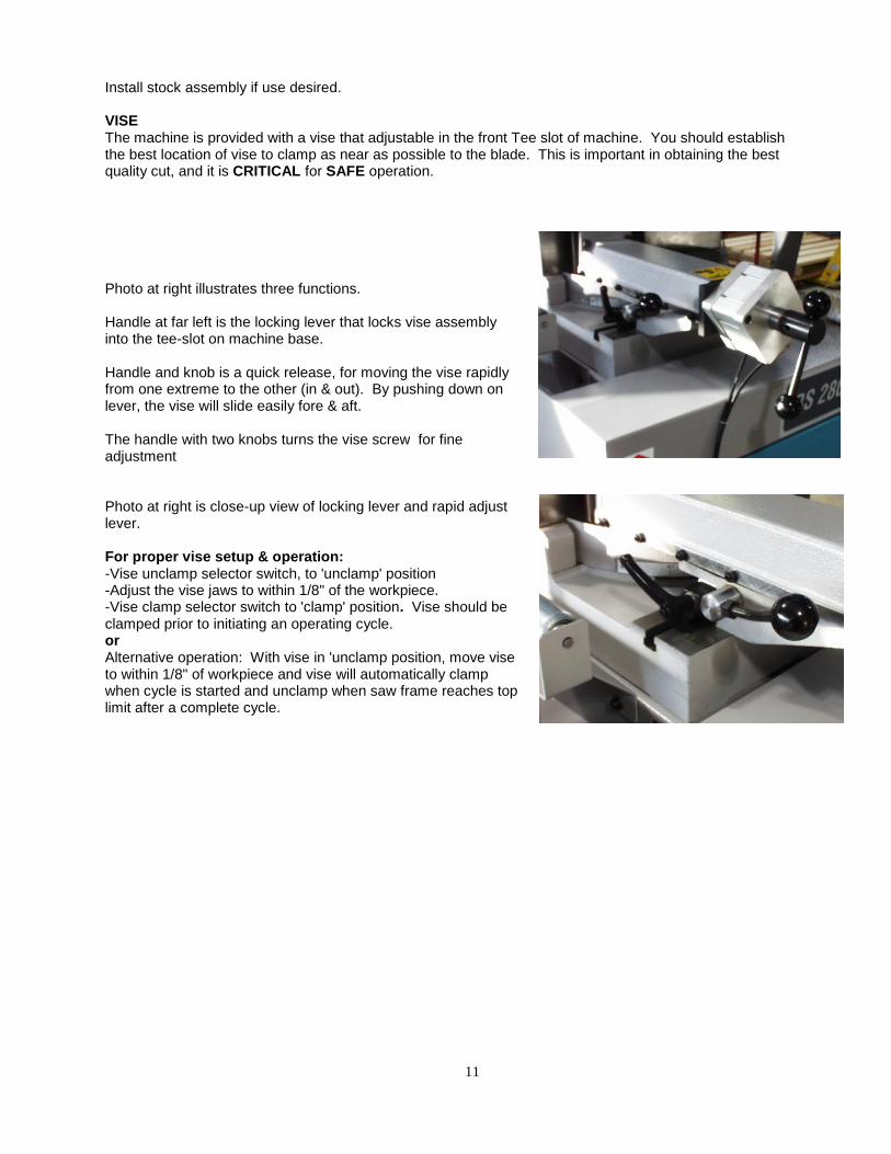
Install stock assembly if use desired. VISE The machine is provided with a vise that adjustable in the front Tee slot of machine. You should establish the best location of vise to clamp as near as possible to the blade. This is important in obtaining the best quality cut, and it is CRITICAL for SAFE operation. Photo at right illustrates three functions. Handle at far left is the locking lever that locks vise assembly into the tee-slot on machine base. Handle and knob is a quick release, for moving the vise rapidly from one extreme to the other (in & out). By pushing down on lever, the vise will slide easily fore & aft. The handle with two knobs turns the vise screw for fine adjustment Photo at right is close-up view of locking lever and rapid adjust lever. For proper vise setup & operation: -Vise unclamp selector switch, to 'unclamp' position -Adjust the vise jaws to within 1/8" of the workpiece. -Vise clamp selector switch to 'clamp' position. Vise should be clamped prior to initiating an operating cycle. or Alternative operation: With vise in 'unclamp position, move vise to within 1/8" of workpiece and vise will automatically clamp when cycle is started and unclamp when saw frame reaches top limit after a complete cycle.
12
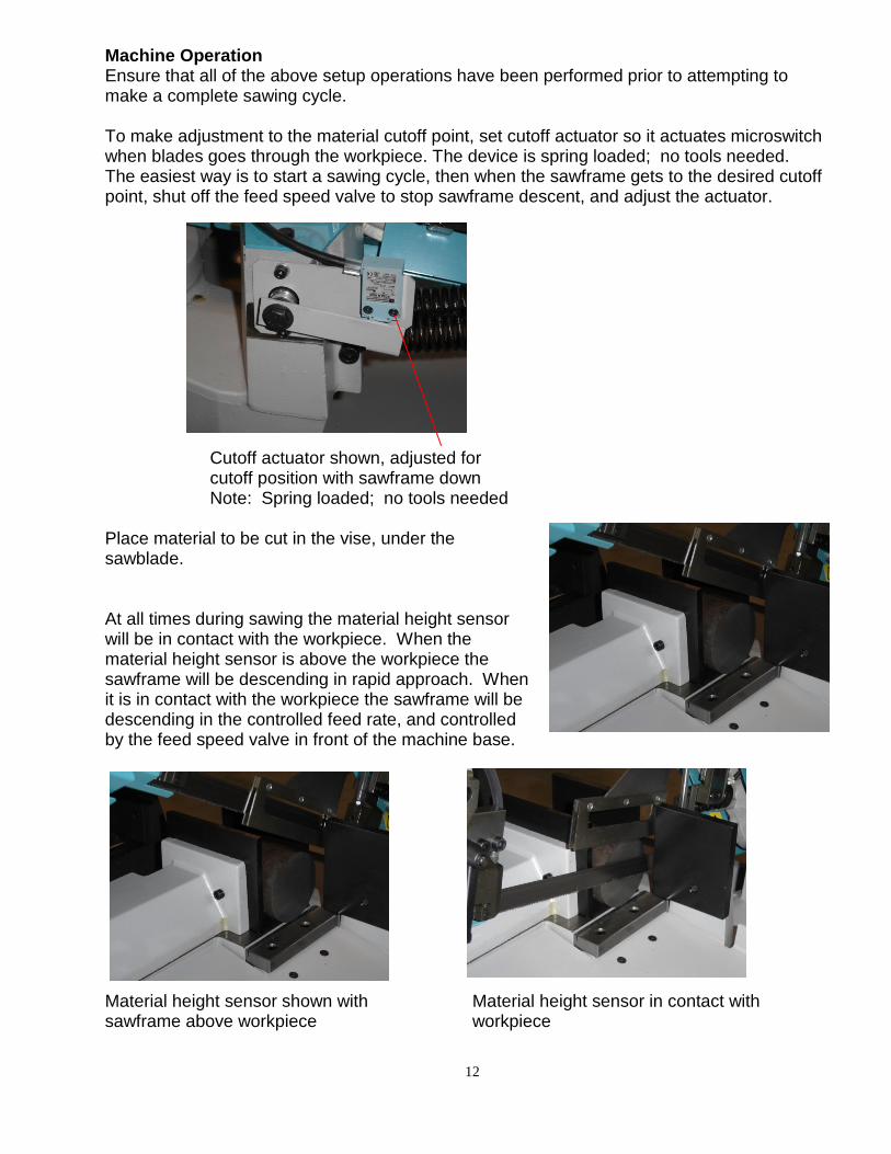
Machine Operation Ensure that all of the above setup operations have been performed prior to attempting to make a complete sawing cycle. To make adjustment to the material cutoff point, set cutoff actuator so it actuates microswitch when blades goes through the workpiece. The device is spring loaded; no tools needed. The easiest way is to start a sawing cycle, then when the sawframe gets to the desired cutoff point, shut off the feed speed valve to stop sawframe descent, and adjust the actuator. Cutoff actuator shown, adjusted for cutoff position with sawframe down Note: Spring loaded; no tools needed Place material to be cut in the vise, under the sawblade. At all times during sawing the material height sensor will be in contact with the workpiece. When the material height sensor is above the workpiece the sawframe will be descending in rapid approach. When it is in contact with the workpiece the sawframe will be descending in the controlled feed rate, and controlled by the feed speed valve in front of the machine base.
Material height sensor shown with Material height sensor in contact with sawframe above workpiece workpiece
13
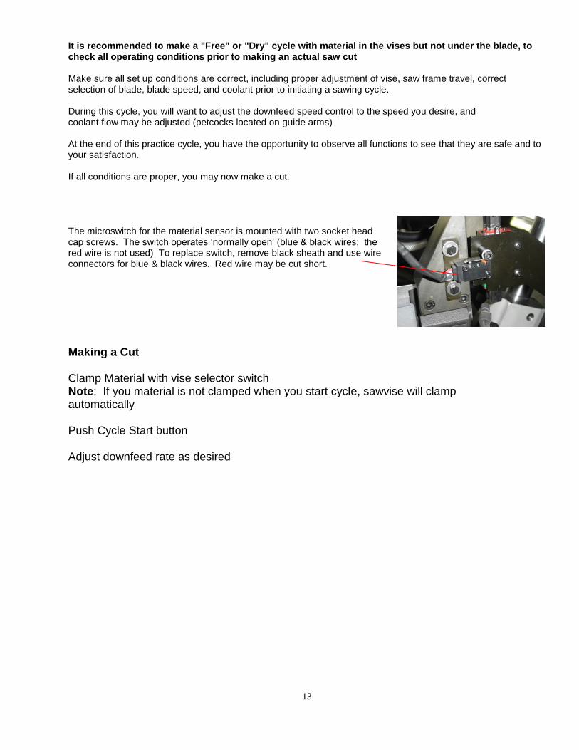
It is recommended to make a "Free" or "Dry" cycle with material in the vises but not under the blade, to check all operating conditions prior to making an actual saw cut Make sure all set up conditions are correct, including proper adjustment of vise, saw frame travel, correct selection of blade, blade speed, and coolant prior to initiating a sawing cycle. During this cycle, you will want to adjust the downfeed speed control to the speed you desire, and coolant flow may be adjusted (petcocks located on guide arms) At the end of this practice cycle, you have the opportunity to observe all functions to see that they are safe and to your satisfaction. If all conditions are proper, you may now make a cut. The microswitch for the material sensor is mounted with two socket head cap screws. The switch operates ‘normally open’ (blue & black wires; the red wire is not used) To replace switch, remove black sheath and use wire connectors for blue & black wires. Red wire may be cut short.
Making a Cut Clamp Material with vise selector switch Note: If you material is not clamped when you start cycle, sawvise will clamp automatically Push Cycle Start button Adjust downfeed rate as desired

14
BLADE INSTALLATION USE GLOVES! THE TEETH ON A BLADE ARE FOR CUTTING! Please refer to the section on APPLICATIONS to select proper blade. Raise saw frame to the point where the blade clears the fixed vise. Disconnect machine power to ensure safe blade change. Loosen LH blade guide adjustable locking handle and move the LH guide close to the RH guide. Swing away rear bandwheel cover (4 latches) and front guard.
Tension end latch Middle latch (2 of) Drive end latch The gas cylinder on the end of the sawframe will allow cover to be held open for blade changing.
15
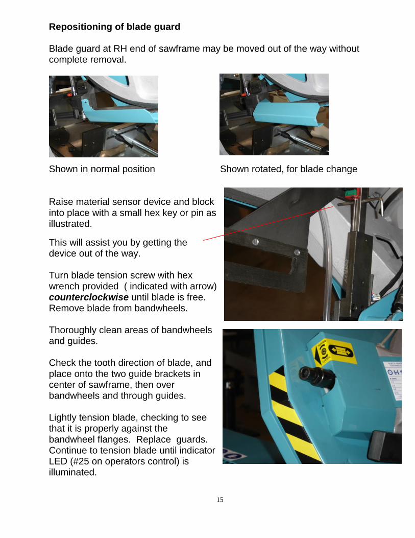
Repositioning of blade guard Blade guard at RH end of sawframe may be moved out of the way without complete removal.
Shown in normal position Shown rotated, for blade change Raise material sensor device and block into place with a small hex key or pin as illustrated.
This will assist you by getting the device out of the way. Turn blade tension screw with hex wrench provided ( indicated with arrow) counterclockwise until blade is free. Remove blade from bandwheels. Thoroughly clean areas of bandwheels and guides. Check the tooth direction of blade, and place onto the two guide brackets in center of sawframe, then over bandwheels and through guides. Lightly tension blade, checking to see that it is properly against the bandwheel flanges. Replace guards. Continue to tension blade until indicator LED (#25 on operators control) is illuminated.

16
OPERATING THE MACHINE Ensure that all of the above setup operations have been performed prior to attempting to make a complete sawing cycle. The first setup adjustment to be made is the material cutoff point. Run the sawframe down until it has reached the point that will completely cut through your material, and set cutoff actuator so it actuates microswitch at cutoff point. The device is spring loaded; no tools needed.
Cutoff actuator shown with sawframe Cutoff actuator shown, adjusted for In fully raised position cutoff position with sawframe down VISE The machine is provided with a vise that adjustable in the front of machine. You should establish the best location of vise to clamp as near as possible to the blade. This is important in obtaining the best quality cut, and it is CRITICAL for SAFE operation. -Push Vise Unclamp key (18) -Loosen lever (1) to slide vise assembly laterally in front slot to desired position. Reclamp. -Loosen lever (2) to slide vise jaw in and out from the workpiece. Reclamp -Adjust the vise jaws to within 1/8" of the workpiece with handwheel (3). -Push Vise Clamp key (19). Vise should be clamped prior to initiating an operating cycle, but in case this is neglected, vise will automatically clamp when cycle is started and unclamp when saw frame reaches top limit after a complete cycle.

17
Place material to be cut in the vise, under the sawblade.

18
Operation Note At all times during sawing the material height sensor will be in contact with the workpiece. When the material height sensor is above the workpiece the sawframe will be descending in rapid approach. When it is in contact with the workpiece the sawframe will be descending in the controlled feed rate, and controlled by the feed speed valve in front of the machine base.
Material height sensor shown with Material height sensor in contact with sawframe above workpiece workpiece Inspect LH guide assembly to ensure it is as close as possible to the workpiece. Push Cycle Start button. Check coolant flow and blade speed, and adjust as necessary. Adjust Feed Speed until you reached desired sawing rate. Additional notes: The microswitch for the material sensor is mounted with two socket head cap screws. The switch operates ‘normally open’ (blue & black wires; the red wire is not used) To replace switch, remove black sheath and use wire connectors for blue & black wires. Red wire may be cut short.

19
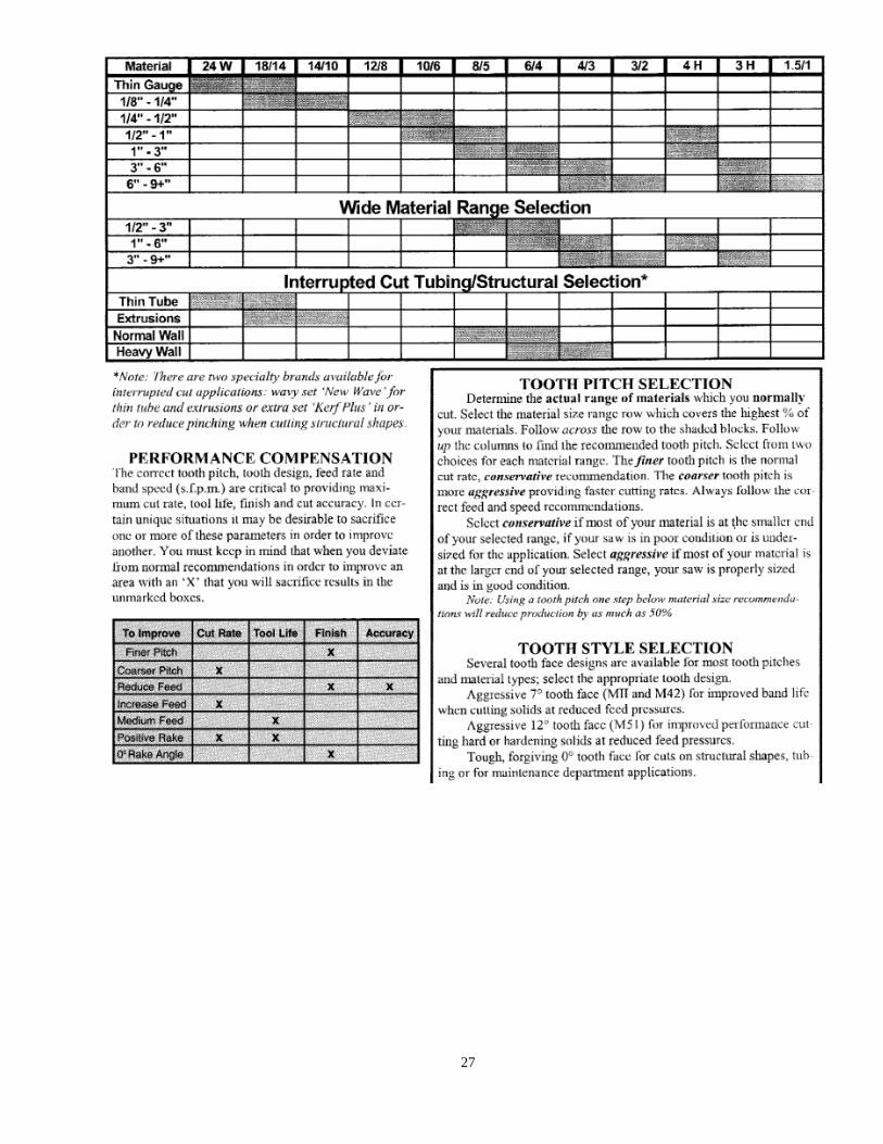
UNDERSTANDING SAWING CONTROLS Successful sawing requires an understanding of the sawing variables. Many sawing problems can be eliminated with proper understanding of the adjustments available to you on your machine.
BLADE SPEED The charts contained in the "Applications" section are a result of years of research and testing by the bandsaw blade manufacturer. Pay attention to them. Make sure you use the proper blade speed for the type and size of material you are cutting. If you have questions, call the factory or your local blade supplier. The correct blade speed ensures that the material is being removed as quickly as possible. Too slow or too fast yields a chip load less than optimum and may dull the blade prematurely. Too slow a blade speed will lead to overloading of teeth and crooked cuts. Observe your chip load. CHIP LOAD Careful observation of the chip load is important when sawing. Chips could be nicely curled as shown in illustration. Too tight a curl may mean too heavy a feed pressure. Lack of a curl shows too little feed pressure. Chips that are blue in color could mean too great a blade speed, too heavy feed pressure, or a combination of the two. FEED SPEED Feed speed valve controls the rate of saw frame descent. The setting should be so that the saw frame moves only as fast as the material is being removed with a proper chipload. Open the valve slowly enough that the blade does not crash into the workpiece and damage the blade. Often it is proper to ease the blade into the workpiece, then gradually open the valve further when the blade is well into the cut.
Angle Cutting Your machine will make angle cuts from 0-45° left & 60° right. To set an angle, first loosen lever behind the fixed vise jaw. Swivel the saw frame until the graduation desired on the swiveling
plate match the indicator on the base. Relock handle. Stops are provided at 60-45-0-45 degrees. It may be necessary to readjust the moving vise jaw and the when miter cutting, as failure to do so may result in interference with the blade.
20
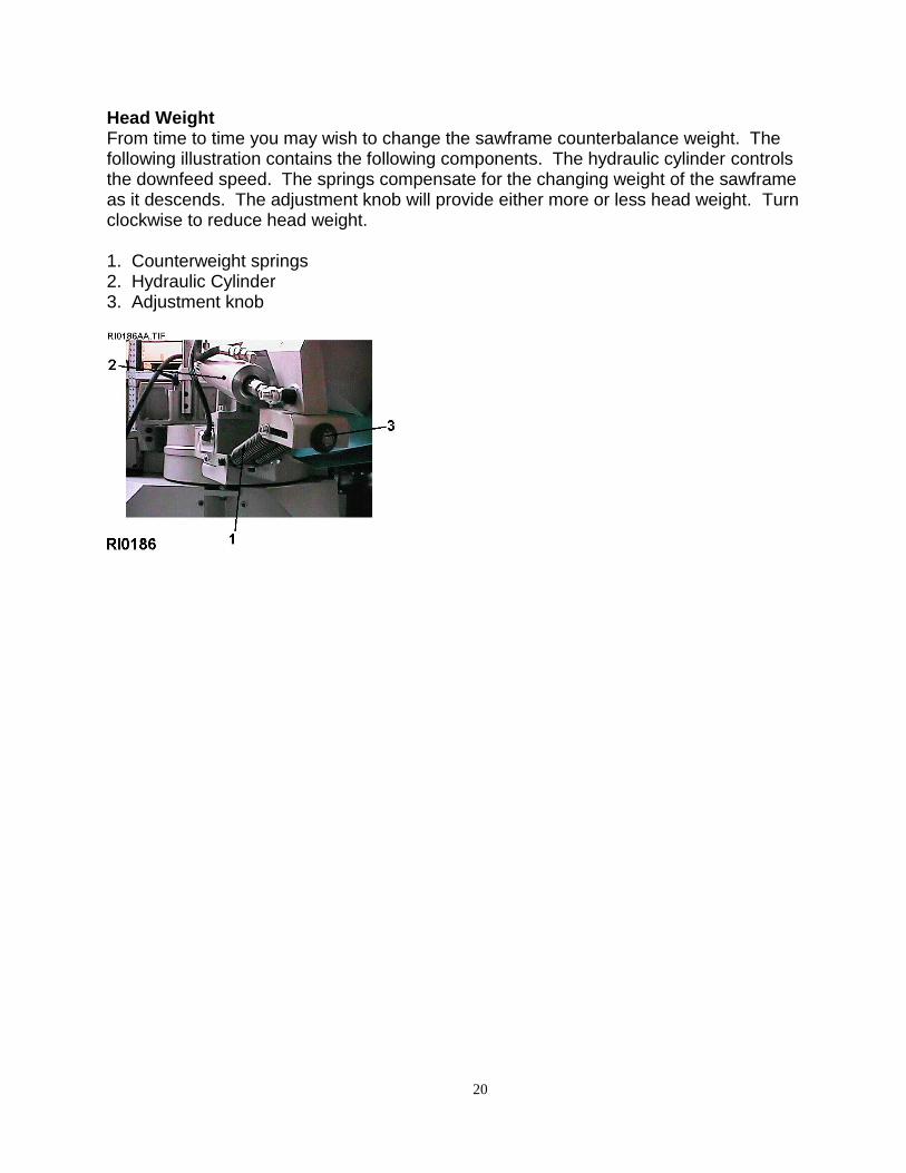
Head Weight From time to time you may wish to change the sawframe counterbalance weight. The following illustration contains the following components. The hydraulic cylinder controls the downfeed speed. The springs compensate for the changing weight of the sawframe as it descends. The adjustment knob will provide either more or less head weight. Turn clockwise to reduce head weight. 1. Counterweight springs 2. Hydraulic Cylinder 3. Adjustment knob

21
1
2
MAINTENANCE DAILY -Clean all chips from machine -Replenish coolant level -Inspect all blades for sharpness -Check blade tension and adjust as necessary WEEKLY
-Remove and clean out coolant tank and replenish with fresh coolant mixture
Yearly -Remove and replace gearbox oil
Oil Level With sawframe in UP position, oil should be visible on end of dip stick illustrated (1) With dipstick removed, this is also the hole through which oil is added.
Drain plug Drain plus is found at bottom rear of gearbox. See illustration for drain plug removal (2)
RECOMMENDED OIL EQUIVALENTS
LUBRICATIONS CHARTLocation Viscosity
Gearbox 100
Hydraulic System 46
Air Regulator/Oiler System 32
22
Variable Speed Drive Will Not Operate
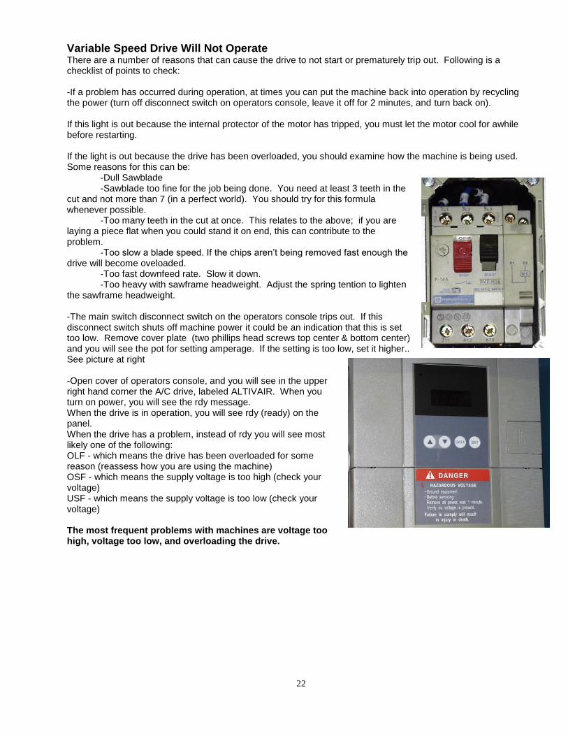
There are a number of reasons that can cause the drive to not start or prematurely trip out. Following is a checklist of points to check: -If a problem has occurred during operation, at times you can put the machine back into operation by recycling the power (turn off disconnect switch on operators console, leave it off for 2 minutes, and turn back on). If this light is out because the internal protector of the motor has tripped, you must let the motor cool for awhile before restarting. If the light is out because the drive has been overloaded, you should examine how the machine is being used. Some reasons for this can be: -Dull Sawblade -Sawblade too fine for the job being done. You need at least 3 teeth in the cut and not more than 7 (in a perfect world). You should try for this formula whenever possible. -Too many teeth in the cut at once. This relates to the above; if you are laying a piece flat when you could stand it on end, this can contribute to the problem. -Too slow a blade speed. If the chips aren’t being removed fast enough the drive will become oveloaded. -Too fast downfeed rate. Slow it down. -Too heavy with sawframe headweight. Adjust the spring tention to lighten the sawframe headweight. -The main switch disconnect switch on the operators console trips out. If this disconnect switch shuts off machine power it could be an indication that this is set too low. Remove cover plate (two phillips head screws top center & bottom center) and you will see the pot for setting amperage. If the setting is too low, set it higher.. See picture at right -Open cover of operators console, and you will see in the upper right hand corner the A/C drive, labeled ALTIVAIR. When you turn on power, you will see the rdy message. When the drive is in operation, you will see rdy (ready) on the panel. When the drive has a problem, instead of rdy you will see most likely one of the following: OLF - which means the drive has been overloaded for some reason (reassess how you are using the machine) OSF - which means the supply voltage is too high (check your voltage) USF - which means the supply voltage is too low (check your voltage) The most frequent problems with machines are voltage too high, voltage too low, and overloading the drive.

23
TROUBLESHOOTING Aside from obvious machine malfunctions, most sawing problems can be attributed to improper practices or applications, and will result in blade problems or unsatisfactory cuts or cutting times. 1. Improper application, i.e. an application not suited to a bandsawing machine 2. Improper blade selection, including -wrong pitch
-wrong type
4. Material improperly clamped in machine vise 5. Improper use of coolant 6. Feed rate too heavy 8. Improper training of saw operator
Sawframe Will Not Swivel Beneath the locking handle is a steel plug that contacts the swiveling turntable. It’s about 20mm in diameter, and it’s possible that rust & corrosion can lock it up. Remove the backfence and clean out this area.
Remove the aluminum insert and you find a grease fitting in item. Grease this. You may also want to clean any junk you find in this area, and use some light oil in the area. Note: If you do not have a grease gun for this type of fitting, please note it is called a “flush-style” grease fitting (with an M8 thread). You will also find tips (adapters) are available that will attach to your standard manual grease gun. You can also take off the other backfence and clean out this area. You must consider the coolant you are using, and how you mix it. You need a good grade of water soluable synthetic, and mix it leaner than 10:1.

24
VEGETABLE BASED COOLANT OF NATURAL ORIGINS CALLED NATUR EP 700 SERIES, WITH THE PRECISE AIM OF IMPROVING DRAMATICALLY THE WORKING ENVIRONMENT CONDITIONS AND IN THE MEANWHILE TO
SUPPLY CUTTING TOOLS PERFORMANCES HIGHER TO THAT ACHIEVABLE WITH THE USE OF
TRADITIONAL CUTTING NEAT MINERAL OILS. NATUR 700 SERIES IS WHOLLY FREE FROM
ANY LUBRICANT MINERAL OIL AND IT IS COMPOSED TOTALLY BY SYNTHETIC ESTERS
DERIVED FROM RAW MATERIALS OF NATURAL ORIGINS. ODOURLESS, LIGHT-COLOURED,
THESE PRODUCTS ARE WHOLLY BIODEGRADABLE AND ABSOLUTELY NON-TOXIC, THE USE OF
NATUR 700 SERIES AVOIDS TOTALLY THE RISK DUE TO THE USE OF MINERAL OILS AND
CONSEQUENTLY THE PERIODICAL MEDICAL VISIT.
IN ADDITION, NATUR 700 EP SERIES HAS AN EXCEPTIONAL LUBRICANT POWER COMBINED
WITH EXTREME PRESSURE PREROGATIVES AND A GOOD COOLING ACTION WHICH KEEPS IT
SUITABLE TO OBTAIN MAXIMAL RESULTS WITH STRONG FEEDS AND WITH THE TYPE OF
WORKING TOOL, AVOIDING GASSINGS AND SEIZING-UP.
NATUR 700 EP SERIES HAS EVEN THE PREROGATIVE TO REDUCE SMOKES, HAS LOW
VOLATILITY WHICH REDUCES NOTEWORTHY STEAM REDUCTION, SUCH AN EXCELLENT
CHEMICAL STABILITY TO AVOID POLYMERISATION OR DEGRADATION OF THE USING
PRODUCT; LAST, BUT NOT THE LEAST, NATUR 700 EP HAS THE CHARACTERISTIC OF AUTO
EXTINGUISHING IMMEDIATELY AT THE ARISING OF A FIRE TRIGGER.
NATUR 707 EP IS A NEAT FLUID WITH COMPLEX ADDITIVATION, WITH VERY HIGH ANTIWELDING
POWER AND CONSPICUOUS EXTREME PRESSURE RESISTANCE, AND, USED WITH
TOOLS OR CERAMIC METAL INSERTS, IT ALLOWS TO DOUBLE THE FEED SPEED IN
COMPARISON WITH THE USUAL PARAMETERS OF USAGE. THE USE OF NATUR 707 EP AVOIDS
SMOKES THAT WOULD DEVELOP WITH TRADITIONAL OILS DURING THE INCREASING FEED
SPEEDS MENTIONED ABOVE. FURTHERMORE, NATUR 707 EP IS SUITABLE TO BE USED ON
GEAR-CUTTING MACHINES USING BOTH CUTTING SYSTEMS SUCH AS “GLEASON” AND
SLOTTING MACHINE SUCH AS “FELLOWS”. NATUR 707 EP IS ALSO WHOLLY FREE OF CHLORINE
AND ITS DERIVATIVES.
PRODUCT SPECIFIC GRAVITY
AT 15 ° C KG/L
VISCOSITY CST AT 40 ° C FLASH POINT ° C.
NATUR 707 EP 0.928 68 290
25
POSSIBLE MACHINE PROBLEMS MOTOR FAILS TO DEVELOP FULL POWER 1. Power line overloaded 2. Undersize wire 3. Low voltage from power company MOTOR OVERHEATS 1. Motor overloaded 2. High or low power supply voltage 3. Air circulation over motor restricted COOLANT FLOW INADEQUATE 1. Valve closed or clogged 2. Coolant tank empty 3. Crimped or restricted coolant line 4. Defective valve 5. Defective or clogged pump 6. Clogged pump filter inside main tank CANNOT MAKE SQUARE CUT 1. Dull blade 2. Wrong blade for application; 3. Blade installed with teeth backwards 4. Vise not set at 90 ° 5. Material not clamped squarely BLADE WILL NOT CUT AT ALL Blade mounted with teeth in wrong direction Blade running wrong direction MOTOR WILL NOT RUN 1. Low voltage 2. Fuse blown or circuit breaker open 5. Open circuit in wiring 6. Motor defective MOTOR WILL NOT START; FUSES BLOW 1. Short circuit in line or cord 2. Short circuit in motor terminal box 3. Fuses too light 4. Defective motor MOTOR STALLS EASILY 1. Low voltage supply 2. Inadequate wiring 3. Excessive pressure being used while sawing 4. Dull blade (in conjunction with above)
PREMATURE DULLING OR BREAKING OF SAWBLADE 1. Cutting speed too fast for material being cut 2. Feed rate too fast 3. Excessive feed pressure 4. Improper blade for material being cut 5. Cutting without proper coolant 6. Wrong coolant for job 7. Fusion of chips in sawblade (coolant problem) 8. Fusion of chips in sawblade (incorrect pitch) 9. Material loose in vise 10. Workpiece not properly clamped in vise, and moving during the cut TEETH STRIPPING FROM BLADE 1. Excessive feed pressure 2. Feed speed too fast 3. Blade speed too slow 4. Gullets of teeth overloading, blade pitch too fine 5. Blade pitch too coarse 6. Workpiece not firmly clamped in vise jaws 7. Workpiece clamped incorrectly. When possible, flat and/or rectangular pieces should be placed on side, to allow cutting through thinnest possible section CROOKED CUTS 1 . Excessive feed pressure 2. Incorrect blade tension 3. Blade speed too slow 4. Too fine pitch of sawblade 5. Blade dull 6. Guides improperly set; gap too wide between carbides 7. Guides set too far from workpiece 8. Vise jaws not square to blade 9. Bandwheel flanges work, causing loss of set to one side of saw teeth SAW BLADE "KICKS" Chips have fused in teeth (see 8 & 9 above)

26
27

28

29

30

31
32
33

34
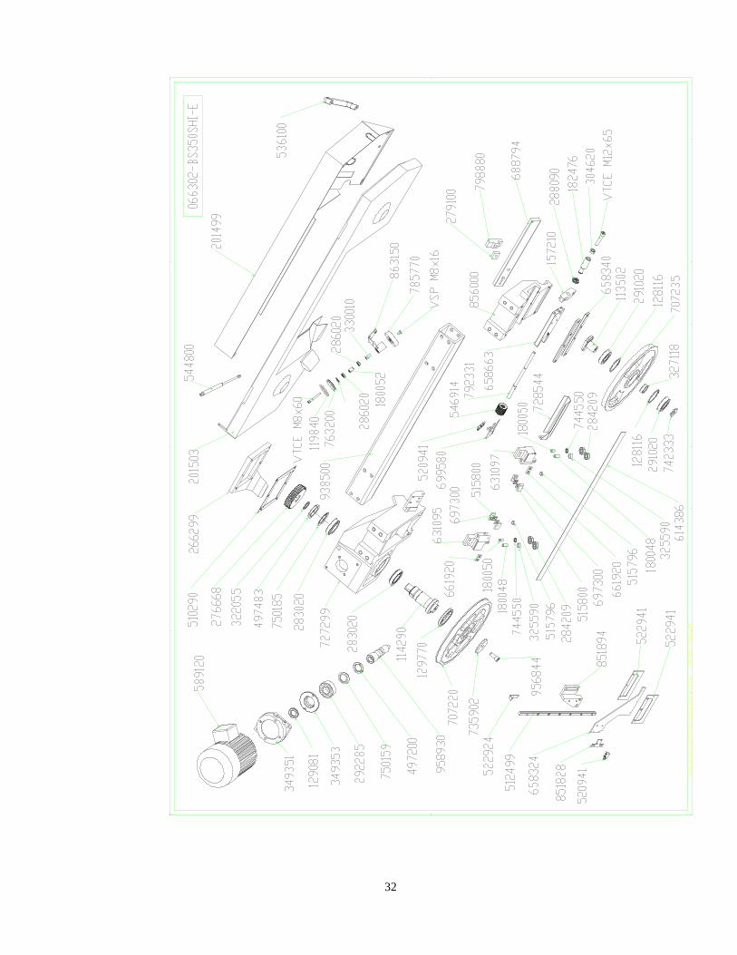
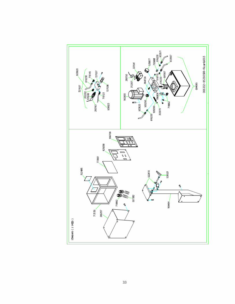
Part# Description 113502--BS 280 FRONT BAND WHEEL SHAFT-- 114290--BS350 BACK BAND WHEEL SHAFT-- 118500--BS350 CENTRAL PIN RING-- 119574--OR RING 3275 2,62X69-- 119840--OR RING 6400 3,34X47-- 127810--SEEGER RING A17 RTD TABLE-- 128030--SEEGER RING J22 / BS350 BRUSH-- 128116--SEEGER INNER RING J72-- 129696--SEAL RING 40X55X7-- 129770--SEAL RING 75X95X12-- 136827--LENGTH STOP ROD D.20 BS340/280-- 141000--FLOOR STAND SIRIO-- 144990--VICE LOCKING CONN.ROD BS350-- 144992--VICE NUT D.20 BS350-- 144995--VICE THREADED BRASS NUT BS350-- 157210--BAND TENSIONER BLOCK 280350NEW-- 157220--VICE ROD FOR BS 350-- 172180--BASE LOCKING BUSH D20 BS280-- 179458--SPACER D.6,5X10X14-- 180048--LEFT BAND GUIDE BUSH BS350-- 180050--RIGHT BAND GUIDE BUSH BS350-- 180052--SPACER D16 BS350-- 181950--CYLINDRICAL BUSH BS350 SHI-- 182433--TEMPERATED BUSH 10X15X12-- 182466--TEMPERATED BUSH 12X18X12-- 182476--BAND STRETCHER BUSH-- 184000--VICE CARRIAGE BS350-- 188051--HIWIN HGW15CAZ0C CARRIAGE-- 201499--TUBE GUARD 12" BS350-- 201503--BAND GUARD-2 PIECES- BS350-- 205328--HYDRAULIC UNIT W/MOTOR-- 205600--ARM BASE HINGE BS280AFI-E--
205900--EL.CONTROL BOX HINGE BS280AFIE-- 216270--KEY 8X7X25 UNI6604-- 222830--CYLINDER SHI D.50-- 227512--BASE FOR BS350 GH/SHI/SHI-E-- 260150--4WAYS CONNECTOR-- 265792--CAM HOLDER COVER BS350 GH-- 265818--ELECTRIC BOARD COVER 350SHIE-- 266299--GEAR BOX COVER-- 267502--UNLOADING ROLLER COVER BS350-- 267504--LOADING ROLLER COVER BS350SHIE-- 276668--BRONZE WHEEL BS350 ME Z37-- 279100--WEDGE FOR BANDGUIDE ROD BS350-- 280060--VICE ADJUSTING WEDGE BS350-- 280765--HK1616 CARRIAGE CONNECTION-- 283020--CARR.CONN. 32010X 50X80X20-- 284209--BEARING 6201.2ZR 12X32X10-- 286020--BRUSH/PUMP CARRIAGE CONNECTION-- 288090--BEARING 51103 ..X..X.-- 291020--CARRIAGE CONNECTION 6207 35X72-- 292285--CARR.CONN. 3207A 35X72X27-- 322055--WHEEL ADJUSTING SPACER 350-- 323380--CYLINDER BACK SPACER 350-- 323385--CYLINDER FRONT SPACER 350-- 327118--PULLEY SPACER D.35X42 BS280-- 327201--HEXAGONAL SPACER 7X65-- 327281--COOLANT DISTRIBUTOR BS280-- 330010--HEXAGONAL BRUSH CONNECTION-- 330050--VICE LOCKING ECCENTRIC BS350-- 330055--VICE RAPID MOVING ECCENTRIC 35--

35
331427--LONG ELECTRIC PUMP 230400460-- 331925--HOSE CLAMP W2 12-20-- 332100--HOSE CLAMP HOP9-- 349351--MOTOR/REDUCTION FLANGE BS350-- 349353--ENDLESS SCREW FLANGE BS350-- 486505--VICE CARRIAGE JAW BS350-- 492788--RIGHT JAW BS350-- 492800--LEFT JAW BS350 SHI-E-- 497200--RING KM7 M35X1,5-- 497303--LOCKING RING KM9 M45X1,5-- 497483--RING KM10 M50X1,5 BS340PR-- 499850--RING M45X1,5-- 510200--ELECTROPUMP SEAL D.130X102-- 510290--REDUCTION GASKET BS350-- 511290--SAW FR.CYL.GASKET MDB2X400501-- 512499--GUIDE HIWIN LGR15R417C 20/37-- 513931--BLACK HANDLE D.12x40-- 514762--BLACK HANDLE DIA. 30-M8-- 515753--OILER M8 CH10-- 515780--SPECIAL INSERT D15,95X6,4-- 515800--SQUARE CARBURE PAD 19,3X4 F.4-- 520941--STROKE-END ABV161660-- 521000--STROKE END SWITCH TELEMEC.-- 521145--STROKE END SWITCH TELEMEC.-- 521580--LEGRAND PLASTIC STRING-- 521652--OIL HOSES SUPPORT FOR BS 350-- 521903--TURNING ARM SUPPORT BS350SHI-E-- 521920--UNDER BASE METAL SHEET, BS 350-- 522100--REDUCTION SPRINGS FIXED GUARD-- 522630--TUBE SUPPORT FOR BS 350-- 522924----- 522941----- 529020--CYLINDER LOCKING LEVER-- 536100--HANDLE UGN565.2-26-160-SW-- 536419--HANDLE M8X20 TYPE 63-- 536521--TURNING HANDLE M10 TYPE80--
536675--TURNING HANDLE M12X45 TYPE 80-- 544800--GAS SPRING 082597 SIR/VEL AF-E-- 546938--SPINDLE CUP SPRING 40X20,4X2,5-- 546957--CUP SPRING 31,5X16,3X2-- 546969--CUP SPRING 25X12,2X1,5-- 547200--SPRING 12X19X2-- 547210--SPRING 14,5X22X2-- 547260--SPRING 22,8X22X1,5-- 547263--HEAD SELECTOR SPRING SIRIO-- 547316--BASE SPRING BS280PLUS/340/350-- 547652--SAW FRAME RETURN SPRING 340280-- 548950--VICE CYLINDER SPRING VTF500-- 589120--3PH MOTOR 2-4P V400 BS350-- 614515-5/7--BAND 3370X27X09 SVGLB M42 5/7-- 616170--BRASS THREADED CONNECTION M4-4-- 616230--OIL THREADED CONNECTION 1/4-- 616628--CONNECTION 1/2"X 1/2"-- 620382--HYDRAULIC OIL 46 CST-- 621898--REDUCTION OIL BS280 EP100CST-- 628489--STROKE-END PLATE BOW DOWN-- 630700--CABLE GLAND PG13,5 MIRKO-- 630975--CABLE GLAND SB1750-22-- 631095--BACK BAND GUIDE BS350-- 631097--FRONT BAND GUIDE BS350-- 631150--LOWER BAND GUIDE BS350-- 631155--FRONT BAND GUIDE BS350-- 632788--BRASS. SPACER D.10-- 646550--SPRINGS CONNECTION PIN L.90-- 651530--OSCILLATING PIN FOR BS 350-- 652790--PLATFORM CENTRAL PIN BS350-- 654710--REDUCTION PLATE BLOCKING PLATE-- 658270--SPRINGS CONNECTION PLATE BS350-- 658324--APPROACHING PLATE BS280--

36
658340--BAND TENSIONING GUIDE PLATE BS-- 658663--FRONT BAND TENS.PLATE 80X20-- 661890--ROLLERS HOLDER FIXING PLATE 35-- 661900--PLATE FOR LOWER BANDGUIDE VTF-- 661915--PLATE FOR BANDSTRETCHER 2XM3-- 661920--BRUSH LOCKING PLATE BS280/60PL-- 667765--DOUBLE PLATE RPD0055-4,8-- 673860--BANDGUIDE STROKE-END PLATE-- 681000--SWIVELING LATFORM BS350-- 688794--MOVING FRONT BAND GUIDE PLATE-- 690814--COOLANT SPRAY GUN-- 694925--RUBB.HOSE CONNECTOR D.14X1/2"-- 696080--NYLON RUBB.HOSE CONNECTOR GES6-- 696224--NYLON RUBB.HOSE CONNECTOR R1/8-- 696346--NYLON PUSH-ON CONNECTOR R1/2-- 697300--PAD SUPPORT FOR BAND GUIDE 350-- 697836--ELECTROPUMP SUPPORT-- 698050--UNLOAD.W40 ROLLER HOLDER BS350-- 698055--W40 LOADING ROLLER HOLDER 350-- 699580--BAND FRONT STROKE-END HOLDER-- 699591--STROKE-END HOLDER NEWAUT-- 707220--PULLEY D.360 BS350-- 707235--PULLEY D.360 BS350-- 712020--BOX FOR KEYBOARD-- 713108--EL.CONTROL PANEL BS350 SHI-E-- 716145--ELBOW CONNECTION G-AMF=5020A1-- 716823--OIL CONNECTION D.6 1/4"-- 718999--OIL CONNECTION D.8 1/4"CON.-- 719061--OIL CONNECTION D.8 1/4"CILE321--
719073--OIL CONNECTION D.6 1/8"-- 722000--3WAY CONNECTION 1/2"-- 722345--CONNECTION T-4FFM-L=4050 1/4"-- 725445--ALUMINIUM LENGTH STOP DEVICE-- 726786--LENGTH STOP ROD D.20 BS340/280-- 727044--CMP.UNIT SPEED REGULATOR ARON-- 727299--FRAME REDUCER BS350-- 727803--REDUCTION PG16F PG13.5M-- 728544--FRONT BAND COVER BS350-- 729295--PLATFORM FRONT COVER BS350-- 734694--COPPER WASHER 1/4-- 734698--COPPER WASHER 1/8-- 735602--SUPPORT WASHER SS22X32X2-- 735902--BACK PULLEY WASHER BS350-- 738976--WASHER 45X12X5-- 741509--SUPPORT WASHER SS20X28X2-- 742333--WASHER 45X35X10,5-- 742431--BURNISHED WASHER 35X10X6-- 744100--WASHER 20X11,5-- 744500--SUPPORT WASHER SS9X15X1,2-- 744550--SUPPORT WASHER SS13X19X1,5-- 744611--PRINTED WASHER 5X15X1,2-- 744715--PRINTED WASHER 6X18X2-- 744820--PRINTED WASHER 8X24X2-- 744987--PRINTED WASHER 12X30X4-- 750011--KNURLED SCHNORR WASHER D.8-- 750159--WASHER MB7 M35X1,5-- 750180--SAFETY WASHER MB9 M45X1,5-- 755801--COCK 6310 1/8"MF-- 755888--COCK ART.400 1/4" FEM/FEM.-- 755995--COCK 405 1/2"MF-- 758760--ROLLER 6X6 BS350-- 763200--BRUSH DRIVE WHEEL FOR BS 350-- 778615--BALL D.12 BS280-- 780850--UNIBALL JOINT SMG10 M10-- 785770--NYLON BRUSH D.100X20-- 788270--ELASTIC PIN 5X10 DIN7343--

37
788320--ELASTIC PIN 5X40 DIN 7343-- 789065--ELASTIC PIN 6X20 DIN7343-- 791620--CYLINDRICAL PIN 10X45 UNI6364-- 791945--CYLINDRICAL PIN 8X26 DIN1472-- 792331--BAND TENSIONING ROD 280350 NEW-- 796809--BRACKET 1"-- 796930--REGULATOR SUPPORT PLATE-- 798880--BANDGUIDE LOCKING BRACKET BS35-- 851799--CYLINDER FRONT SUPPORT BS350-- 851828----- 851894---- 851900--VICE CARRIAGE SUPPORT BS350-- 856999--RIGHT JAW SUPPORT BS350-- 857100--LEFT JAW SUPPORT BS350 SH/GH-- 863150--BRUSH SUPPORT BS350-- 864724--OIL PLUG+GASKET 1/4"-- 865362--PLUG+BAR ALS 2-18-- 911015--PLATFORM GRADUATED PLATE BS350-- 918592--PLATE BOSS FOR BS 350-- 918677--EL. KEYBOARD TRON 8+8-- 929345--TIE ROD M12X140 BS350-- 933571--TUBE R6 3/8"-- 933577--TUBE R6 3/8" 3080-- 933597--TUBE R6 3/8" 2350-- 933800--SPRINGS FIXING TUBE BS350-- 935493--PLASTIC TUBE 13X19 ARIANNA-- 936823--TUBE R7 1/4" 5100-- 937763--TUBE R7 3/16" 2900-- 938500--TUBULAR SAW FRAME BS350-- 940000--PILOT CHECK VALVE ATOS=HRO13-- 940895--ELECTRIC PUMP TANK DELTA 20-- 956843--LEFT SCREW TE M14X30-- 957132--VICE SCREW BS 350 SHI-- 958930--ENDLESS SCREW BS350 GH-- 962402--WHEEL 733-50 12H7X20 M5-- 964234--WHEEL 19912520H7PFT-O--
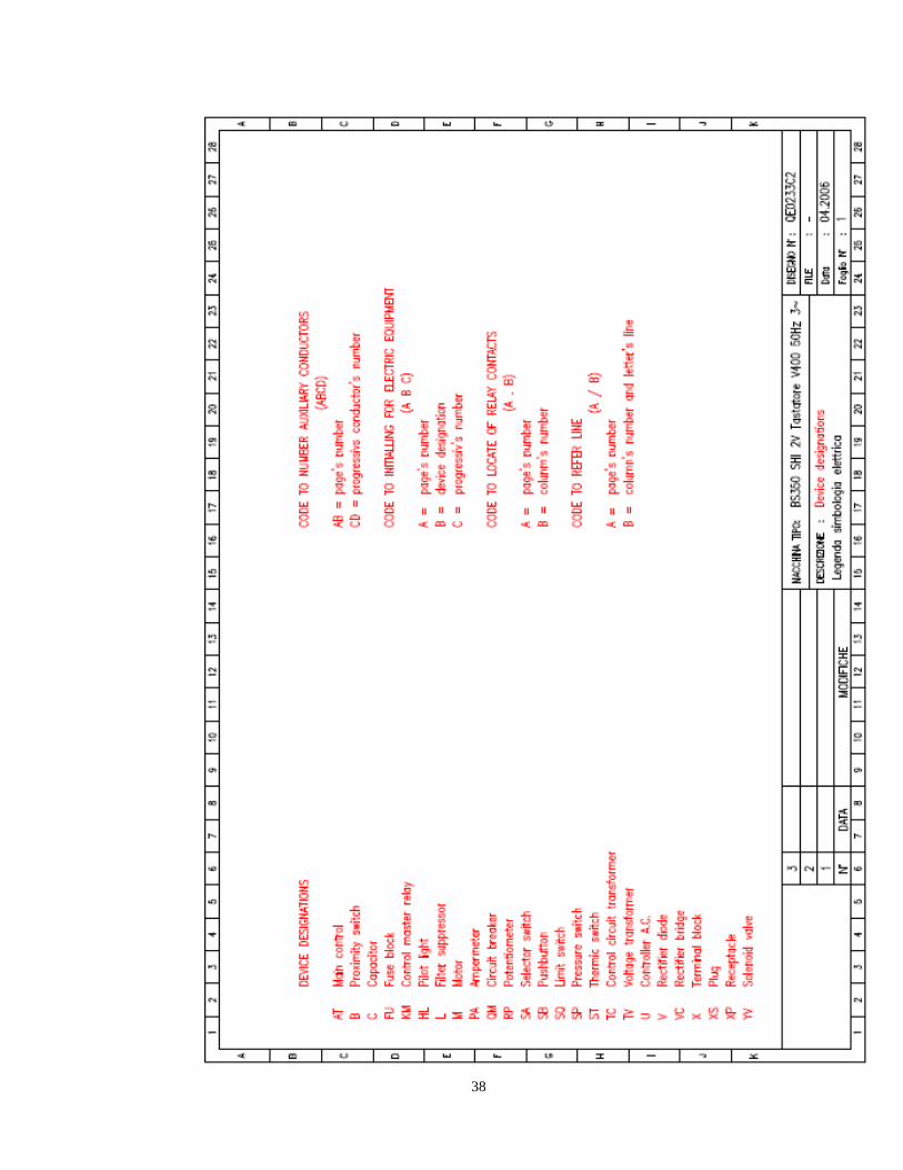
38
39
40
41

42
43
44

45
46

47
48

49

50