operating instructions and parts manual dual mitering...
TRANSCRIPT

1
Operating Instructions and Parts Manual Dual Mitering EVS Band Saw Models MBS-1323EVS-H, MBS-1323EVS-H-4
JET 427 New Sanford Road LaVergne, Tennessee 37086 Part No. M-413412 Ph.: 800-274-6848 Edition 5 04/2018 www.jettools.com Copyright © 2018 JET

2
1.0 IMPORTANT SAFETY INSTRUCTIONS
WARNING – To reduce risk of injury:
1. Read and understand the entire owner's manual before attempting assembly or operation.
2. Read and understand the warnings posted on the machine and in this manual. Failure to comply with all of these warnings may cause serious injury.
3. Replace the warning labels if they become obscured or removed.
4. This band saw is designed and intended for use by properly trained and experienced personnel only. If you are not familiar with the proper and safe operation of a band saw, do not use until proper training and knowledge have been obtained.
5. Do not use this band saw for other than its intended use. If used for other purposes, JET disclaims any real or implied warranty and holds itself harmless from any injury that may result from that use.
6. Always wear ANSI Z87.1 approved safety glasses or face shield while using this band saw. (Everyday eyeglasses only have impact resistant lenses; they are not safety glasses.)
7. Before operating this machine, remove tie, rings, watches and other jewelry, and roll sleeves up past the elbows. Do not wear loose clothing. Confine long hair. Non-slip footwear or anti-skid floor strips are recommended. Do not wear gloves.
8. Wear ear protectors (plugs or muffs) if noise exceeds safe levels.
9. CALIFORNIA PROPOSITION 65 WARNING: This product contains chemicals known to the State of California to cause cancer, or birth defects or other reproductive harm.
10. This product, when used for welding, cutting, or working with metal, produces fumes, gases, or dusts which contain chemicals known to the State of California to cause birth defects and, in some cases, cancer. (California Health and Safety Code Section 25249.5 et seq.)
11. Make certain the switch is in the OFF position before connecting the machine to the power supply.
12. Make certain the machine is properly grounded.
13. Make all machine adjustments or maintenance with the machine unplugged from the power source.
14. Remove adjusting keys and wrenches. Form a habit of checking to see that keys and adjusting wrenches are removed from the machine before turning it on.
15. Keep safety guards in place at all times when the machine is in use. If removed for maintenance purposes, use extreme caution and replace the guards immediately after completion of maintenance.
16. Check damaged parts. Before further use of the machine, a guard or other part that is damaged should be carefully checked to determine that it will operate properly and perform its intended function. Check for alignment of moving parts, binding of moving parts, breakage of parts, mounting and any other conditions that may affect its operation. A guard or other part that is damaged should be properly repaired or replaced.
17. Provide for adequate space surrounding work area and non-glare, overhead lighting.
18. Keep the floor around the machine clean and free of scrap material, oil and grease.
19. Keep visitors a safe distance from the work area. Keep children away.
20. Make your workshop child proof with padlocks, master switches or by removing starter keys.
21. Give your work undivided attention. Looking around, carrying on a conversation and “horse-play” are careless acts that can result in serious injury.
22. Maintain a balanced stance at all times so that you do not fall into the blade or other moving parts. Do not overreach or use excessive force to perform any machine operation.
23. Use the right tool at the correct speed and feed rate. Do not force a tool or attachment to do a job for which it was not designed. The right tool will do the job better and more safely.
24. Use recommended accessories; improper accessories may be hazardous.
25. Maintain tools with care. Keep saw blades sharp and clean for the best and safest performance. Follow instructions for lubricating and changing accessories.
26. Maintain proper adjustment of blade tension, blade guides and thrust bearings.
27. Turn off the machine before cleaning. Use a brush to remove chips or debris — do not use your hands.

3
28. Do not stand on the machine. Serious injury could occur if the machine tips over.
29. Never leave the machine running unattended. Turn the power off and do not leave the machine until it comes to a complete stop.
30. Remove loose items and unnecessary work pieces from the area before starting the machine.
31. Never hand hold the material. Always use the vise and clamp it securely.
32. Be sure that blade is not in contact with workpiece when motor is started. Allow motor to come up to speed before bringing blade into contact with workpiece.
33. Avoid contact with coolant, especially guarding your eyes.
34. Never reach around or over saw blade during operation. Keep hands and fingers away from blade area.
35. Do not remove jammed pieces until blade has stopped.
36. Don’t use in dangerous environment. Don’t use power tools in damp or wet location, or expose them to rain. Keep work area well lighted.
37. Use proper extension cord. Make sure your extension cord is in good condition. When using an extension cord, be sure to use one heavy enough to carry the current your product will draw. An undersized cord will cause a drop in line voltage resulting in loss of power and overheating. Table 2 (sect. 6.3) shows correct size to use depending on cord length and nameplate ampere rating. If in doubt, use the next heavier gage. The smaller the gage number, the heavier the cord.
Familiarize yourself with the following safety notices used in this manual:
This means that if precautions are not heeded, it may result in minor injury and/or possible machine damage.
This means that if precautions are not heeded, it may result in serious, or possibly even fatal, injury.
4
2.0 Table of contents Section Page 1.0 IMPORTANT SAFETY INSTRUCTIONS ....................................................................................................... 2 2.0 Table of contents ............................................................................................................................................ 4 3.0 About this manual .......................................................................................................................................... 5 4.0 Specifications ................................................................................................................................................. 6 5.0 Setup and assembly ....................................................................................................................................... 8
5.1 Shipping contents ....................................................................................................................................... 8 5.2 Unpacking and cleanup .............................................................................................................................. 8 5.3 Installation .................................................................................................................................................. 8
6.0 Electrical connections .................................................................................................................................... 8 6.1 GROUNDING INSTRUCTIONS ................................................................................................................. 8 6.2 Extension cords .......................................................................................................................................... 9
7.0 Adjustments ................................................................................................................................................... 9 7.1 Blade installation and removal ................................................................................................................... 9 7.2 Guide post adjustment ............................................................................................................................... 9 7.3 Blade guide adjustment .............................................................................................................................. 9 7.4 Blade tension and tracking ....................................................................................................................... 10 7.5 Belt tension ............................................................................................................................................... 11 7.6 Vise adjustment ........................................................................................................................................ 11 7.7 Bow swivel adjustment ............................................................................................................................. 12 7.8 Material stop ............................................................................................................................................. 12 7.9 Coolant flow .............................................................................................................................................. 12
8.0 Control panel ................................................................................................................................................ 12 9.0 Operation ..................................................................................................................................................... 13
9.1 Automatic shut-off .................................................................................................................................... 13 9.2 Auxiliary coolant hose .............................................................................................................................. 13 9.3 Prior to Operation ..................................................................................................................................... 13 9.4 General operating procedure ................................................................................................................... 13 9.5 Evaluating cutting efficiency ..................................................................................................................... 14 9.6 Blade selection ......................................................................................................................................... 14 9.7 Blade break-in procedures ....................................................................................................................... 14
10.0 User-maintenance ...................................................................................................................................... 15 10.1 General cleaning .................................................................................................................................... 15 10.2 Lubrication .............................................................................................................................................. 15 10.3 Belt replacement .................................................................................................................................... 15 10.4 Additional servicing ................................................................................................................................ 15
11.0 Optional accessory ..................................................................................................................................... 15 12.0 Troubleshooting MBS-1323EVS-H Band Saw ........................................................................................... 16 13.0 Replacement Parts ..................................................................................................................................... 17
13.1.1 MBS-1323EVS-H Bow Assembly – Exploded View ............................................................................ 18 13.1.2 MBS-1323EVS-H Bow Assembly – Parts List ..................................................................................... 19 13.2.1 MBS-1323EVS-H Base Assembly – Exploded View ........................................................................... 22 13.2.2 MBS-1323EVS-H Base Assembly – Parts List .................................................................................... 23 13.3.1 MBS-1323EVS-H Electrical Box Assembly – Exploded View ............................................................. 25 13.3.2 MBS-1323EVS-H Electrical Box Assembly – Parts List ...................................................................... 25
14.0 Electrical Connections for MBS-1323EVS-H ............................................................................................. 26 14.1 230V Only ............................................................................................................................................... 26 14.2 460V Only ............................................................................................................................................... 27
15.0 Warranty and service ................................................................................................................................. 28
5
3.0 About this manual This manual is provided by JET, covering the safe operation and maintenance procedures for a JET Model MBS-1323EVS-H Mitering Band Saw. This manual contains instructions on installation, safety precautions, general operating procedures, maintenance instructions and parts breakdown. Your machine has been designed and constructed to provide consistent, long-term operation if used in accordance with the instructions as set forth in this document.
If there are questions or comments, please contact your local supplier or JET. JET can also be reached at our web site: www.jettools.com.
Retain this manual for future reference. If the machine transfers ownership, the manual should accompany it.
Read and understand the entire contents of this manual before attempting assembly or operation! Failure to comply may cause serious injury!
Register your product using the mail-in card provided, or register online: http://www.jettools.com/us/en/service-and-support/warranty/registration/
6
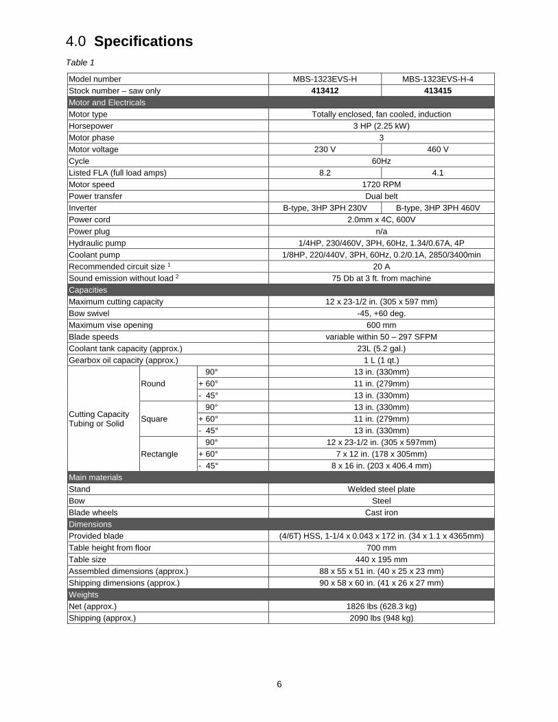
4.0 Specifications Table 1
Model number MBS-1323EVS-H MBS-1323EVS-H-4 Stock number – saw only 413412 413415 Motor and Electricals Motor type Totally enclosed, fan cooled, induction Horsepower 3 HP (2.25 kW) Motor phase 3 Motor voltage 230 V 460 V Cycle 60Hz Listed FLA (full load amps) 8.2 4.1 Motor speed 1720 RPM Power transfer Dual belt Inverter B-type, 3HP 3PH 230V B-type, 3HP 3PH 460V Power cord 2.0mm x 4C, 600V Power plug n/a Hydraulic pump 1/4HP, 230/460V, 3PH, 60Hz, 1.34/0.67A, 4P Coolant pump 1/8HP, 220/440V, 3PH, 60Hz, 0.2/0.1A, 2850/3400min Recommended circuit size 1 20 A Sound emission without load 2 75 Db at 3 ft. from machine Capacities Maximum cutting capacity 12 x 23-1/2 in. (305 x 597 mm) Bow swivel -45, +60 deg. Maximum vise opening 600 mm Blade speeds variable within 50 – 297 SFPM Coolant tank capacity (approx.) 23L (5.2 gal.) Gearbox oil capacity (approx.) 1 L (1 qt.)
Cutting Capacity Tubing or Solid
Round 90° 13 in. (330mm) + 60° 11 in. (279mm) - 45° 13 in. (330mm)
Square 90° 13 in. (330mm) + 60° 11 in. (279mm) - 45° 13 in. (330mm)
Rectangle 90° 12 x 23-1/2 in. (305 x 597mm) + 60° 7 x 12 in. (178 x 305mm) - 45° 8 x 16 in. (203 x 406.4 mm)
Main materials Stand Welded steel plate Bow Steel Blade wheels Cast iron Dimensions Provided blade (4/6T) HSS, 1-1/4 x 0.043 x 172 in. (34 x 1.1 x 4365mm) Table height from floor 700 mm Table size 440 x 195 mm Assembled dimensions (approx.) 88 x 55 x 51 in. (40 x 25 x 23 mm) Shipping dimensions (approx.) 90 x 58 x 60 in. (41 x 26 x 27 mm) Weights Net (approx.) 1826 lbs (628.3 kg) Shipping (approx.) 2090 lbs (948 kg)

7
1 subject to local and national electrical codes 2 The specified values are emission levels and are not necessarily to be seen as safe operating levels. As workplace conditions vary, this information is intended to allow the user to make a better estimation of the hazards and risks involved only.
L = length, W = width, H = height n/a = not applicable
The specifications in this manual were current at time of publication, but because of our policy of continuous improvement, JET reserves the right to change specifications at any time and without prior notice, without incurring obligations.

8
Read and understand all assembly instructions before attempting assembly. Failure to comply may cause serious injury.
5.0 Setup and assembly
Disconnect band saw from power during setup.
5.1 Shipping contents 1 Band saw 1 Splash plate 1 Tool box containing: 6 Leveling pads 1 Set of open-end wrenches 1 Set of hex wrenches 1 Cross-point screwdriver 1 Adjustable wrench, 12 in. 6 Hex cap bolts, 1/2-20 x 2in. 6 Hex nuts, 1/2in.
5.2 Unpacking and cleanup 1. Finish uncrating saw and inspect for damage.
Should any have occurred, contact your local distributor. Do not discard any packing material until saw is set up and running properly.
2. Remove all bolts attaching machine to shipping pallet. (The wood support beam can be removed after machine has been connected to power and the bow raised.)
3. Clean all rust protected surfaces with a cleaner-degreaser or kerosene to remove protective coating. Do not use gasoline, paint thinner, mineral spirits, etc. These may damage painted surfaces.
4. Lubricate all slideways with SAE 10W oil.
5. Compare contents of shipping carton with the contents list in this manual. Report shortages, if any, to your distributor.
5.3 Installation 1. The band saw should be located on a solid and
level foundation, preferably concrete. Allow room for bow swiveling, servicing and for moving large stock around the machine.
2. Use lifting straps that are isolated from the band saw’s finished surfaces and knobs, to move machine to desired location. Position straps under secure areas; do not strap bow or vise assembly.
3. Install leveling bolts/nuts/pads, and the leveling feet as desired, through the base flanges.
4. Place a level on the table surface and check side-to-side and front-to-back.
5. Adjust leveling screws until machine is level in both directions and tighten nuts against the base flanges.
6. Install material stop into front hole in table, as shown in Figure 7-9.
7. Fill coolant reservoir with 15L (4 gal.) of appropriate coolant, by pouring it through the filter screen atop the pan.
8. Install splash plate over lip of base and below cutting area. This deflects coolant and chips down into the base.
6.0 Electrical connections
Electrical connections must be made by a qualified electrician in compliance with all relevant codes. This machine must be properly grounded to help prevent electrical shock and possible fatal injury.
The MBS-1323EVS-H Horizontal Band Saw is wired for 3-phase, 230V; the MBS-1323EVS-H-4 is wired for 3-phase 460V. The machine is not provided with an electrical plug; you may either attach a proper UL/CSA-listed plug, or “hardwire” the machine directly to a service panel.
It is recommended that the band saw be connected to a dedicated 20 amp circuit with circuit breaker or time-delay fuse marked “D”. Local codes take precedence over recommendations.
Before connecting to power source, be sure switch is in off position.
6.1 GROUNDING INSTRUCTIONS This tool must be grounded. In the event of a malfunction or breakdown, grounding provides a path of least resistance for electric current to reduce the risk of electric shock. This tool is equipped with an electric cord having an equipment-grounding conductor. If a plug is used, it must be plugged into a matching outlet that is properly installed and grounded in accordance with all local codes and ordinances.
Improper connection of the equipment-grounding conductor can result in a risk of electric shock. The conductor with insulation having an outer surface that is green with or without yellow stripes is the equipment-grounding conductor. If repair or replacement of the electric cord or plug is necessary, do not connect the equipment-grounding conductor to a live terminal.
Check with a qualified electrician or service personnel if the grounding instructions are not completely understood, or if in doubt as to whether the tool is properly grounded. Failure to comply may cause serious or fatal injury.

9
If hardwired:
Permanently connected tools: This tool should be connected to a grounded metal permanent wiring system; or to a system having an equipment-grounding conductor. Make sure a disconnect is available for the operator. During hard-wiring of the machine, make sure the fuses have been removed or the breakers have been tripped in the circuit to which the drill press will be connected. ALWAYS FOLLOW PROPER LOCK-OUT/TAG-OUT PRO-CEDURES.
6.2 Extension cords The use of extension cords is discouraged; try to position equipment within reach of the power source. If an extension cord becomes necessary, be sure it is heavy enough to carry the current your product will draw. An undersized cord will cause a drop in line voltage resulting in loss of power and overheating.
Table 2 shows recommended size to use depending on cord length and nameplate ampere rating. If in doubt, use the next heavier gauge. The smaller the gauge number, the heavier the cord.
Ampere Rating Volts Total length of
cord in feet
More Than
Not More Than
240 50 100 200 300
AWG
0 6 18 16 16 14 6 10 18 16 14 12 10 12 16 16 14 12
12 16 14 12 Not Recommended
Extension Cord Recommendations Table 2
7.0 Adjustments
Disconnect machine from power source before making adjustments, unless indicated otherwise.
7.1 Blade installation and removal Refer to Figure 7-1.
Always wear leather gloves when handling blades to avoid injury.
A blade (1-1/4 in. W x 172 in. L) is pre-installed and tensioned on saw. To replace blade:
1. Raise bow about 15-degrees and keep it in raised position by turning feed rate control knob clockwise all the way (see sect. 8.0).
2. Disconnect machine from power source.
3. Open both wheel covers (A, Figure 7-1) and clean out any swarf from wheel areas.
4. Remove red blade guards (B).
5. Back off the blade guides by loosening knob (H, Figure 7-2). Back off the wire chip brush.
6. Release blade tension by turning blade tension handwheel (C) counter-clockwise.
7. Remove blade from both wheels and out of each blade guide.
8. Make sure teeth of new blade are pointing in direction of travel. If necessary, turn blade inside out.
9. Position new blade around wheels and through upper slot. Slide it into blade guide bearings with back edge of blade contacting backup bearing. (see Figure 7-2). For further guide bearing adjustment, see sect. 7.3
10. Lightly increase tension (C) and position blade so it rests against shoulder of both wheels.
11. When blade is properly positioned, place full tension upon it (see sect. 7.4.1).
12. Reinstall blade guards (B).
13. Adjust chip brush up against blade teeth.
14. Jog the start/stop buttons to ensure blade is tracking properly. If tracking adjustment is needed, see sect. 7.4.2.
15. Close wheel covers.
Figure 7-1: blade changing
7.2 Guide post adjustment The blade guide posts (D, Figure 7-1) must be set to just clear the workpiece, but should not interfere with workpiece or other saw components during bow’s descent.
Loosen knobs and slide posts into position. Always tighten knobs before operating machine.
7.3 Blade guide adjustment The bearing and carbide guides come pre-adjusted from the factory for the installed blade. If adjustment is needed, or if a blade is replaced, follow the below steps for left and right guides.

10
Refer to Figures 7-2 and 7-3.
1. Disconnect machine from power source.
2. To adjust eccentric bearings, loosen hex socket cap screw (K1, Figure 7-2) about one full turn.
3. Turn hex nut (K2) with wrench until ball bearings are approximately 0.003” from blade. Note: Do not pinch blade.
4. Tighten hex socket cap screw (K1) while holding hex nut (K2) in place.
5. Repeat for other blade guide assembly.
Figure 7-2: blade guide bearing adjustment
6. Turn knurled knob (L, Figure 7-3) to adjust carbide top (M1) and side (M2) guides. Guides should place light pressure on blade. Do not overtighten.
Figure 7-3: carbide guide adjustment
7.4 Blade tension and tracking Refer to Figure 7-4.
7.4.1 Tension Blade tension has been set by manufacturer at approximately 1800 kg/cm2 (25,000 psi) for the supplied blade. Turn handwheel (C, Figure 7-4) clockwise; if collar (N) slips out of position, then blade is properly tensioned. Continue turning handwheel until collar re-engages. NOTE: Simply turn handwheel, do not press on it.
If tension mechanism will not move blade, loosen and then re-tighten socket head cap screws on gibs (X, Figure 7-3).
7.4.2 Tracking
Tracking is performed with wheel covers open and blade moving. Use extreme caution so that you do not come into contact with blade.
Blade tracking has been set by manufacturer. Adjustment is rarely required when blade is used properly and is correctly welded.
Tracking is set properly when back of blade lightly touches shoulder of wheels. Note: Over-tracking (allowing blade back to rub hard against wheel shoulder) may damage blade wheels and blade.
If blade is not tracking properly:
1. Raise bow enough to allow saw motor to operate.
2. Open wheel cover and remove left blade guard.
3. Back off left and right bearing guide assemblies.
NOTE: Maintain proper tension at all times using the blade tensioning mechanism.
4. Loosen center locking screws (O, Figure 7-4) in all three hex adjustment screws (P) on tensioning mechanism.
Figure 7-4: blade tension and tracking
While performing the following, keep blade from excessively rubbing on wheel shoulder, which may damage wheel and/or blade.
5. Start saw. Slowly turn single hex adjustment screw (P1) to tilt idler wheel. Do not turn either of the other two adjustment screws. Turn adjustment screw until blade is touching shoulder of idler wheel.
NOTE: Turning screw inward causes blade to move toward wheel shoulder. Turning screw outward causes blade to move away from shoulder.
11
6. Turn single hex adjustment screw (P1) so blade starts to move away from wheel shoulder. Then immediately turn single hex adjustment screw in opposite direction so that blade stops, then moves slowly toward shoulder.
Keep fingers clear of blade and wheel to avoid injury.
7. Turn single hex adjustment screw (P1) to stop motion of blade on wheel as it gets closer to wheel shoulder. Put a 6-inch length of paper between blade and wheel. The paper should not be cut as it passes between wheel shoulder and blade.
8. Turn single hex adjustment screw (P1) a small amount. Repeat insertion of paper between wheel shoulder and blade until paper is cut in two pieces. NOTE: You may have to repeat the check with the paper several times before blade and shoulder cuts paper into two pieces. Do not hurry this adjustment; patience and accuracy here will pay off with better, more accurate, quieter cutting and much longer machine and blade life.
9. When the paper is cut, turn hex adjustment screw (P1) slightly counterclockwise. This assures that blade is not rubbing excessively against wheel shoulder.
10. Shut off saw.
11. Hold hex adjustment screws (P, P1) with a wrench and tighten center locking screws (O). Make sure hex adjustment screws do not move while tightening center screws.
12. Adjust left and right bearing guide assemblies. See sect. 7-3.
13. Install left blade guard and close wheel cover.
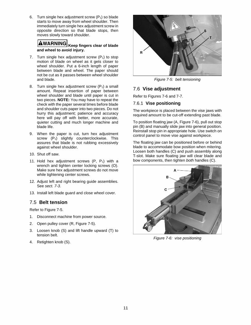
7.5 Belt tension Refer to Figure 7-5.
1. Disconnect machine from power source.
2. Open pulley cover (R, Figure 7-5).
3. Loosen knob (S) and lift handle upward (T) to tension belt.
4. Retighten knob (S).
Figure 7-5: belt tensioning
7.6 Vise adjustment Refer to Figures 7-6 and 7-7.
7.6.1 Vise positioning The workpiece is placed between the vise jaws with required amount to be cut-off extending past blade.
To position floating jaw (A, Figure 7-6), pull out stop pin (B) and manually slide jaw into general position. Reinstall stop pin in appropriate hole. Use switch on control panel to move vise against workpiece.
The floating jaw can be positioned before or behind blade to accommodate bow position when mitering. Loosen both handles (C) and push assembly along T-slot. Make sure floating jaw will clear blade and bow components, then tighten both handles (C).
Figure 7-6: vise positioning

12
7.6.2 Vise pressure adjustment Open rear door and adjust hydraulic clamping pressure of vise with knob (D, Figure 7-7); clockwise to increase. Recommended pressure is between 10 to 12 kg/cm2 (142 to 170 PSI).
Figure 7-7: hydraulic system
7.7 Bow swivel adjustment Refer to Figures 7-8 and 7-9.
1. Remove 90° stop pin (E).
2. Lift up on lever (F) and push bow to desired angle according to scale and pointer (G).
3. Push down lever (F) all the way until it locks into position. If lever will not push all the way down or does not have sufficient tightness to secure bow, adjust screw beneath lever (F1).
Figure 7-8: bow swivel adjustment
Figure 7-9: bow locking lever
7.8 Material stop Refer to Figure 7-10.
The material stop is generally used when cutting multiple pieces to the same length. Position stop block (H) desired distance away from blade and tighten knob.
If closer reach is needed over table, insert small rod and upper knob (J).
Figure 7-10: material stop
7.9 Coolant flow
Coolant pump must be submerged before operating to prevent damage to pump.
The blade guides are fitted with coolant valves. Coolant is provided to the fittings through interconnecting tubing, and is dispensed directly onto saw blade.
Adjust coolant flow valves to provide desired flow. The flow should be no more than blade can draw into the workpiece by its movement through the material.
The coolant flow can be stopped in two ways: Turn off coolant pump switch on control panel, or close coolant flow valves.
8.0 Control panel Refer to Figure 8-1.
Figure 8-1: control panel
Feed rate control (A) – Sets amount of downward force that is applied to saw blade. The feed rate is proportional to opening of valve. Increasing valve opening (counterclockwise) increases feed rate; decreasing valve opening (clockwise) reduces feed rate. When set to zero, bow is locked in raised position.
Start button (B) – Press to start main motor/blade.
Stop button (C) – Press to stop main motor/blade. Coolant will still flow.

13
Bow movement (D) – Raises or lowers bow.
Coolant switch (E) – Turn arrow to “I” to turn on coolant flow. Turn arrow to “O” to stop coolant flow.
Power indicator light (F) – illuminates whenever machine is operating.
If bulb is out, light will not be on but machine may still have power.
Manual/auto selector (G) – Choice of manual or automatic bow movement.
Vise close (H) – Press and hold to clamp workpiece in vise. Vise will stop when pressure reaches 10kg/cm2.
Vise open (I) – Press and hold to release workpiece.
LED readout (J) – Identifies blade speed in surface feet per minute.
Blade speed selector (K) – Clockwise increases speed.
Emergency stop button (L) – Press to immediately stop all machine functions. To restart machine, rotate button clockwise until it disengages.
9.0 Operation
9.1 Automatic shut-off 9.1.1 Cut completion Limit switches (A, Figure 9-1) control bow movement. Saw must automatically shut off when cut is completed. The switches are pre-set by the manufacturer, but can be adjusted if needed.
Figure 9-1: auto shut-off switch
9.1.2 Blade breakage If the blade breaks during operation, a sensor near drive wheel will shut off the saw (Figure 9-2).
Figure 9-2: blade break sensor
9.2 Auxiliary coolant hose The saw is equipped with auxiliary coolant hose and spray nozzle. This can be used to direct greater volume of coolant at workpiece, or for washing off table area.
9.3 Prior to Operation 1. Check that blade tooth direction matches
diagram on blade guard, and blade guides are properly set.
2. Check to see that blade is properly seated on wheels after applying correct tension (approximately 25,000 lbs.).
3. Select proper speed and feed rate for material being cut.
4. Material to be cut must be securely held in vise.
5. Check to see that coolant level is adequate and turn on coolant pump if material to be cut requires it. Machine should be filled with approximately 23L (5.2 gal.) of proper coolant mixture. Follow directions on product maker’s label and fill coolant tank through chip tray area.
6. Do not start cut on a sharp edge.
7. Keep machine lubricated. See sect. 10.2.
9.4 General operating procedure
All blade covers and machine guards must be in place and secured before turning on band saw.
1. Select proper speed on digital readout for type of material to be cut.
2. Raise bow high enough to clear workpiece.
Make sure blade is not in contact with workpiece when motor is started.
3. Place stock between vise jaws, set stock for desired width of cut and tighten vise. (See Figure 9-3 for recommended placement in vise of varied workpiece shapes.)

14
4. Make sure left blade guide post is adjusted as close as possible to left vise jaw.
5. Select auto or manual mode.
6. Start motor and allow machine to reach operating speed.
7. Turn on coolant and adjust coolant valves as desired.
8. Turn feed rate control knob for desired rate, then press blade descent button. Allow blade to slowly enter workpiece.
9. Blade will stop running at completion of cut, whether in auto or manual mode.
IMPORTANT: In manual mode, bow will remain in down position – select up direction with switch (D, Figure 8-1) to raise bow. In auto mode, after cut completion bow will rise to original position.
Figure 9-3
9.5 Evaluating cutting efficiency Is the blade cutting efficiently? The best way to determine this is to observe the chips formed by the cutting blade:
If chip formation is powdery, then feed rate is much too light, or blade is dull.
If chips formed are curled, but colored — that is, either blue or straw-colored from heat generated during the cut — then feed rate is too high.
If chips are slightly curled and are not colored by heat — blade is sufficiently sharp and is cutting at its most efficient rate.
9.6 Blade selection The saw is provided with a blade that is adequate for a variety of cut-off jobs on a variety of common materials.
See Table 3 for recommended speeds for various materials. These selections, while appropriate for many shop cutting needs, do not encompass the wide variety of blades of special configuration (tooth pitch and set) and special alloys for cutting unusual or exotic materials.
A coarse blade could be used for a solid steel bar but a finer tooth blade would be used on a thin-wall tube. In general, the blade choice is determined by the thickness of the material; the thinner the material, the finer the tooth pitch.
A minimum of three teeth should be on the work piece at all times for proper cutting. The blade and workpiece can be damaged if the teeth are so far apart that they straddle the workpiece.
For very high production on cutting of special materials, or to work hard-to-cut materials such as stainless steel, tool steel, or titanium, ask your industrial distributor for more specific blade recommendations. Also, the supplier who provides the workpiece material should be prepared to provide very specific instructions regarding the best blade (and coolant or cutting fluid, if needed) for the material and shape supplied.
Speed/FPM Material 100 Tool Steel, Stainless Steel,
Phosphor Bronze, Hard Bronze, Hard Cast Iron, Malleable Iron
165 Mild Steel, Soft Cast Iron, Med. Hard Brass, Med.Hard Bronze
230 Soft Brasses and Bronzes, Hard Aluminum, Plastics
Table 3
9.7 Blade break-in procedures New blades are very sharp, and therefore have a tooth geometry which is easily damaged if a careful break-in procedure is not followed. Consult the blade manufacturer’s literature for break-in of specific blades on specific materials. However, the following procedure will be adequate for break-in of JET-supplied blades on lower alloy ferrous materials.
1. Clamp a round section workpiece in the vise. The workpiece should be 2 inches or larger in diameter.
2. Set saw on low speed. Start cut with a very light feed rate.
3. When saw has completed 1/3 of cut, increase feed rate slightly and allow saw to complete the cut.
15
4. Keep the same settings and begin a second cut on the same or similar workpiece.
5. When blade has completed about 1/3 of cut, increase feed rate. Watch chip formation until cutting is at its most efficient rate (sect. 9.5) and allow saw to complete the cut. The blade is now considered ready for regular service.
10.0 User-maintenance
Always disconnect power to machine before performing maintenance. Failure to comply may result in serious personal injury.
10.1 General cleaning Keep wheels clear of chips and debris.
Keep slide areas (such as vise ways and T-slot, slide for bow swivel, and behind the scale where the guide posts slide) clean and oiled.
Keep a light coat of SAE 10W oil on machined parts to inhibit rust.
Keep proximity switches and sensors clear of dirt or dust.
10.2 Lubrication All ball bearings are permanently lubricated and sealed; they require no further attention.
Coolant – Maintain proper coolant level. Clean chip sludge from coolant tank as needed. Replace coolant on a frequency appropriate to type of coolant being used. Oil-based coolants can sour. Refer to coolant supplier’s instructions for frequency.
Hydraulic cylinder pivot – apply a light oil every 6 months.
Blade tension screw – grease every 6 months.
Wire brush bearing – apply a light oil monthly.
10.2.1 Hydraulic system The hydraulic oil tank has been prefilled by the manufacturer. Check oil level in sight glass (Figure 7-7). If oil needs to be added, pour through fill plug hole.
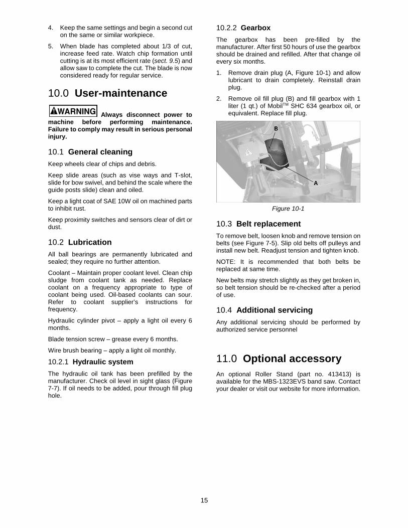
10.2.2 Gearbox The gearbox has been pre-filled by the manufacturer. After first 50 hours of use the gearbox should be drained and refilled. After that change oil every six months.
1. Remove drain plug (A, Figure 10-1) and allow lubricant to drain completely. Reinstall drain plug.
2. Remove oil fill plug (B) and fill gearbox with 1 liter (1 qt.) of MobilTM SHC 634 gearbox oil, or equivalent. Replace fill plug.
Figure 10-1
10.3 Belt replacement To remove belt, loosen knob and remove tension on belts (see Figure 7-5). Slip old belts off pulleys and install new belt. Readjust tension and tighten knob.
NOTE: It is recommended that both belts be replaced at same time.
New belts may stretch slightly as they get broken in, so belt tension should be re-checked after a period of use.
10.4 Additional servicing Any additional servicing should be performed by authorized service personnel
11.0 Optional accessory An optional Roller Stand (part no. 413413) is available for the MBS-1323EVS band saw. Contact your dealer or visit our website for more information.

16
12.0 Troubleshooting MBS-1323EVS-H Band Saw Symptom Possible Cause Correction*
Excessive blade breakage
Material loose in vise. Clamp work securely.
Incorrect speed or feed. Check machinery handbook for speed/ feed appropriate for material being cut.
Teeth too coarse for material. Check machinery handbook for recommended blade type.
Incorrect blade tension. Adjust blade tension to the point where the blade just does not slip on the wheel.
Saw blade is in contact with workpiece before the saw is started.
Start the motor before placing the saw on the workpiece.
Blade rubs on wheel flange. Adjust blade tracking.
Misaligned guides. Adjust guides.
Cracking at weld. Longer annealing cycle.
Premature blade dulling Blade teeth too coarse. Use a finer tooth blade.
Blade speed too high. Try a lower blade speed.
Inadequate feed pressure. Decrease spring tension.
Hard spots in workpiece or scale on/in workpiece.
Increase feed pressure (hard spots). Reduce speed, increase feed pressure (scale).
Work hardening of material (especially stainless steel).
Increase feed pressure by reducing spring tension.
Insufficient blade tension. Increase tension to proper level.
Operating saw without pressure on workpiece.
Do not run blade at idle in/on material.
Bad cuts (out-of-square)
Workpiece not square with blade. Adjust vise so it is square with the blade. (Always clamp work tightly in vise.)
Feed pressure too fast. Decrease pressure.
Guide bearings not adjusted properly.
Adjust guide bearing clearance to 0.001 inch (0.002 inch maximum).
Inadequate blade tension. Gradually increase blade tension.
Span between the two blade guides too wide.
Move blade guide bar closer to work.
Dull blade. Replace blade.
Incorrect blade speed. Check blade speed/pulley position.
Blade guide assembly is loose. Tighten blade guide assembly.
Blade guide bearing assembly loose. Tighten blade guide bearing assembly.
Blade track too far away from wheel flanges.
Adjust blade tracking.
Guide bearing worn. Replace worn bearing.
Bad cuts (rough)
Blade speed too high for feed pressure.
Reduce blade speed and feed pressure.
Blade too coarse. Replace with finer blade.
Blade is twisting Blade is binding in the cut. Decrease feed pressure.
Blade tension too high. Decrease tension on blade

17
Symptom Possible Cause Correction*
Unusual wear on side or back of blade
Blade guides worn Replace blade guides.
Blade guide bearings not adjusted. Adjust blade guide bearings.
Blade guide bearing bracket is loose. Tighten blade guide bearing bracket.
Teeth missing/ripped from blade
Blade tooth pitch too coarse for workpiece.
Use blade with finer tooth pitch.
Feed too slow; feed too fast. Increase feed pressure and/or blade speed.
Workpiece vibrating. Clamp workpiece securely.
Gullets loading up with chips. Use blade with coarse tooth pitch—reduce feed pressure. Brush blade to remove chips.
Motor running too hot Blade tension too high. Reduce tension on blade.
Drive belt tension too high. Reduce tension on drive belt.
Blade too coarse for workpiece (especially with tubular stock).
Use blade with fine tooth pitch.
Blade too fine for workpiece (especially with heavier, soft material).
Use blade with coarse tooth pitch.
Insufficient gearbox lubrication Check gearbox oil.
No coolant flow Pump motor is burned out. Replace pump.
Screen/filter on pump is clogged. Clean screen/filter.
Impeller is loose. Tighten impeller.
Coolant level too low. Add coolant to reservoir.
Excessive noise or vibration
Belt is too tight. Reset belt tension.
Blade runs excessively hot; blade warpage
No or insufficient lubricant. Check operation of lubrication valves and nozzles.
Side carbide guides too tight on blade. Loosen side carbide guides about 1/4 turn of knurled knob.
*Warning: Some corrections may require a qualified electrician.
Table 4
13.0 Replacement Parts Replacement parts are listed on the following pages. To order parts or reach our service department, call 1-800-274-6848 Monday through Friday, 8:00 a.m. to 5:00 p.m. CST. Having the Model Number and Serial Number of your machine available when you call will allow us to serve you quickly and accurately.
Non-proprietary parts, such as fasteners, can be found at local hardware stores, or may be ordered from JET. Some parts are shown for reference only, and may not be available individually.
18
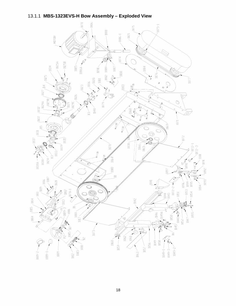
13.1.1 MBS-1323EVS-H Bow Assembly – Exploded View

19
13.1.2 MBS-1323EVS-H Bow Assembly – Parts List
Index No Part No Description Size Qty 1001 .......... MBS1323EVS-1001 ...... Front Blade Wheel ............................................... ...................................... 1 1002 .......... MBS-1018-1-5 ............... Slide ..................................................................... ...................................... 1 1003 .......... EHB916V-02 ................. Shroud .................................................................. ...................................... 1 1004 .......... EHB916V-03 ................. Tension Screw ..................................................... ...................................... 1 1005 .......... EHB916V-19 ................. Thrust Bearing Housing ....................................... ...................................... 1 1006 .......... EHB916V-18 ................. Driven Dog .......................................................... ...................................... 1 1007 .......... MBS-1018-1-6 ............... Gib ........................................................................ ...................................... 2 1008 .......... EHB916V-13 ................. Front Spindle ........................................................ ...................................... 1 1009 .......... MBS1323EVS-1009 ...... Handwheel ........................................................... ...................................... 1 1009-1 ....... MBS1323EVS-1009-1 ... Collar .................................................................... ...................................... 1 1009-2 ....... MBS1323EVS-1009-2 ... Blade Tension Gauge .......................................... ...................................... 1 1009-3 ....... TS-0270061 .................. Set Screw ............................................................. 5/16"-18×5/8" ................ 2 1010 .......... EHB916V-21 ................. Disc Spring ........................................................... ...................................... 6 1011 .......... MBS-1018-1-4 ............... Slide Seat ............................................................. ...................................... 1 1012 .......... EHB916V-20 ................. Lock nut ................................................................ ...................................... 1 1013 .......... EHB916V-07 ................. Lock Ring ............................................................. ...................................... 1 1014 .......... TS-0060111 .................. Hex Cap Screw .................................................... 3/8x2-1/2 ....................... 3 1015 .......... EHB916V-10 ................. Adjusting Screw ................................................... 3/4x1-1/2 ....................... 3 1016 .......... TS-0081051 .................. Hex Cap Screw .................................................... 5/16x1" .......................... 4 1017 .......... TS-0060061 .................. Hex Cap Screw .................................................... 3/8"x1-1/4" .................... 1 1018 .......... EHB916V-26 ................. Special Washer .................................................... ...................................... 1 1019 .......... TS-0732061 .................. Lock Washer ........................................................ 3/8" ................................ 1 1020 .......... TS-0060061 .................. Hex Cap Screw .................................................... 3/8x1-1/4 ....................... 1 .................. MBS1323EVS-ABTA ..... Adjust Blade Tension Assembly (includes 1002-1007, 1009-1016, 1019-1020) ..... ...................................... 1 1021 .......... MBS1323EVS-1021 ...... Input Pulley .......................................................... ...................................... 1 1022 .......... MBS1323EVS-1022 ...... Gear Box Housing ................................................ ...................................... 1 1023 .......... MBS1323EVS-1023 ...... End Cap (Right) ................................................... ...................................... 1 1024 .......... MBS1323EVS-1024 ...... End Cap (Left) ...................................................... ...................................... 1 1025 .......... MBS1323EVS-1025 ...... Lower Cap ............................................................ ...................................... 1 1025A ........ TS-0267121 .................. Set Screw ............................................................. 1/4"×3/4" ....................... 3 1025B ........ TS-0561011 .................. Nut ........................................................................ 1/4" ................................ 3 1026 .......... MBS1323EVS-1026 ...... Worm .................................................................... ...................................... 1 1027 .......... MBS1323EVS-1027 ...... Worm Gear ........................................................... ...................................... 1 1028 .......... KS-7750 ........................ Key ....................................................................... 7 x 7 x 50L .................... 1 1029 .......... MBS1323EVS-1029 ...... Worm Shaft .......................................................... ...................................... 1 1029A ........ MBS1323EVS-1029A .... Retaining Ring ...................................................... ...................................... 1 1029B ........ 5508917 ........................ Key, Double Rd Hd .............................................. 8 x 8 x 35 L ................... 1 1029C ........ 5508917 ........................ Key, Double Rd Hd .............................................. 8 x 8 x 35 L ................... 1 1030 .......... MBS1323EVS-1030 ...... Rear Blade Wheel ................................................ ...................................... 1 1031 .......... MBS1323EVS-1031 ...... Upper Cap ............................................................ ...................................... 1 1032 .......... MBS1323EVS-1032 ...... Special Washer .................................................... ...................................... 1 1033 .......... MBS1323EVS-1033 ...... Collar .................................................................... ...................................... 1 1034 .......... TS-0208061 .................. Socket Head Cap Screw ...................................... 5/16” – 18 x 1” ............... 6 1035 .......... TS-0207031 .................. Socket Head Cap Screw ...................................... 1/4” – 20 x 5/8” .............. 4 1036 .......... TS-0207031 .................. Socket Head Cap Screw ...................................... 1/4” – 20 x 5/8” .............. 4 1037 .......... TS-0207031 .................. Socket Head Cap Screw ...................................... 1/4” – 20 x 5/8” .............. 4 1038 .......... TS-0267121 .................. Set Screw ............................................................. 1/4"×3/4" ....................... 3 1038A ........ TS-0561011 .................. Nut ........................................................................ 1/4" ................................ 3 1039 .......... MBS1323EVS-1039 ...... Oil Seal ................................................................. 50 x 72 x 12 .................. 1 1040 .......... MBS1323EVS-1040 ...... Oil Seal ................................................................. 30 x 45 x 8 .................... 1 .................. MBS1323EVS-GBA ...... Gear Box Assembly (includes 1022-1029, 1031-1040,B3-B5) ................... 1 1041 .......... MBS1323EVS-1041 ...... Bracket ................................................................. ...................................... 2 1042 .......... MBS1323EVS-1042 ...... Slide Way ............................................................. ...................................... 1 1043 .......... MBS1323EVS-1043 ...... Blade Guide Post ................................................. ...................................... 2 1044 .......... MBS1323EVS-1044 ...... Locking Piece ....................................................... ...................................... 2 1045 .......... MBS1323EVS-1045 ...... Carbide Guide ...................................................... ...................................... 4 1046 .......... MBS1323EVS-1046 ...... Top Carbide Guide ............................................... ...................................... 2 1047 .......... MBS1323EVS-1047 ...... Disc Spring ........................................................... ...................................... 4 1048 .......... MBS1323EVS-1048 ...... Carbide Guide Adjusting Screw ........................... ...................................... 2
20
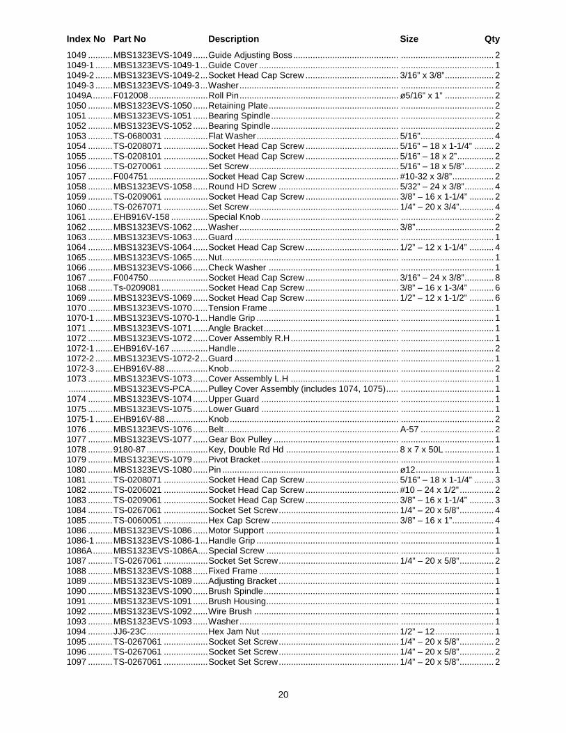
Index No Part No Description Size Qty 1049 .......... MBS1323EVS-1049 ...... Guide Adjusting Boss ........................................... ...................................... 2 1049-1 ....... MBS1323EVS-1049-1 ... Guide Cover ......................................................... ...................................... 1 1049-2 ....... MBS1323EVS-1049-2 ... Socket Head Cap Screw ...................................... 3/16” x 3/8” .................... 2 1049-3 ....... MBS1323EVS-1049-3 ... Washer ................................................................. ...................................... 2 1049A ........ F012008 ........................ Roll Pin ................................................................. ø5/16” x 1” .................... 2 1050 .......... MBS1323EVS-1050 ...... Retaining Plate ..................................................... ...................................... 2 1051 .......... MBS1323EVS-1051 ...... Bearing Spindle .................................................... ...................................... 2 1052 .......... MBS1323EVS-1052 ...... Bearing Spindle .................................................... ...................................... 2 1053 .......... TS-0680031 .................. Flat Washer .......................................................... 5/16" .............................. 4 1054 .......... TS-0208071 .................. Socket Head Cap Screw ...................................... 5/16” – 18 x 1-1/4” ........ 2 1055 .......... TS-0208101 .................. Socket Head Cap Screw ...................................... 5/16” – 18 x 2” ............... 2 1056 .......... TS-0270061 .................. Set Screw ............................................................. 5/16” – 18 x 5/8” ............ 2 1057 .......... F004751 ........................ Socket Head Cap Screw ...................................... #10-32 x 3/8” ................. 2 1058 .......... MBS1323EVS-1058 ...... Round HD Screw ................................................. 5/32” – 24 x 3/8” ............ 4 1059 .......... TS-0209061 .................. Socket Head Cap Screw ...................................... 3/8” – 16 x 1-1/4” .......... 2 1060 .......... TS-0267071 .................. Set Screw ............................................................. 1/4” – 20 x 3/4” .............. 4 1061 .......... EHB916V-158 ............... Special Knob ........................................................ ...................................... 2 1062 .......... MBS1323EVS-1062 ...... Washer ................................................................. 3/8” ................................ 2 1063 .......... MBS1323EVS-1063 ...... Guard ................................................................... ...................................... 1 1064 .......... MBS1323EVS-1064 ...... Socket Head Cap Screw ...................................... 1/2” – 12 x 1-1/4” .......... 4 1065 .......... MBS1323EVS-1065 ...... Nut ........................................................................ ...................................... 1 1066 .......... MBS1323EVS-1066 ...... Check Washer ..................................................... ...................................... 1 1067 .......... F004750 ........................ Socket Head Cap Screw ...................................... 3/16” – 24 x 3/8” ............ 8 1068 .......... Ts-0209081 ................... Socket Head Cap Screw ...................................... 3/8” – 16 x 1-3/4” .......... 6 1069 .......... MBS1323EVS-1069 ...... Socket Head Cap Screw ...................................... 1/2” – 12 x 1-1/2” .......... 6 1070 .......... MBS1323EVS-1070 ...... Tension Frame ..................................................... ...................................... 1 1070-1 ....... MBS1323EVS-1070-1 ... Handle Grip .......................................................... ...................................... 1 1071 .......... MBS1323EVS-1071 ...... Angle Bracket ....................................................... ...................................... 1 1072 .......... MBS1323EVS-1072 ...... Cover Assembly R.H ............................................ ...................................... 1 1072-1 ....... EHB916V-167 ............... Handle .................................................................. ...................................... 2 1072-2 ....... MBS1323EVS-1072-2 ... Guard ................................................................... ...................................... 1 1072-3 ....... EHB916V-88 ................. Knob ..................................................................... ...................................... 2 1073 .......... MBS1323EVS-1073 ...... Cover Assembly L.H ............................................ ...................................... 1 .................. MBS1323EVS-PCA ....... Pulley Cover Assembly (includes 1074, 1075) ..... ...................................... 1 1074 .......... MBS1323EVS-1074 ...... Upper Guard ........................................................ ...................................... 1 1075 .......... MBS1323EVS-1075 ...... Lower Guard ........................................................ ...................................... 1 1075-1 ....... EHB916V-88 ................. Knob ..................................................................... ...................................... 2 1076 .......... MBS1323EVS-1076 ...... Belt ....................................................................... A-57 .............................. 2 1077 .......... MBS1323EVS-1077 ...... Gear Box Pulley ................................................... ...................................... 1 1078 .......... 9180-87 ......................... Key, Double Rd Hd .............................................. 8 x 7 x 50L .................... 1 1079 .......... MBS1323EVS-1079 ...... Pivot Bracket ........................................................ ...................................... 1 1080 .......... MBS1323EVS-1080 ...... Pin ........................................................................ ø12 ................................ 1 1081 .......... TS-0208071 .................. Socket Head Cap Screw ...................................... 5/16” – 18 x 1-1/4” ........ 3 1082 .......... TS-0206021 .................. Socket Head Cap Screw ...................................... #10 – 24 x 1/2” .............. 2 1083 .......... TS-0209061 .................. Socket Head Cap Screw ...................................... 3/8” – 16 x 1-1/4” .......... 3 1084 .......... TS-0267061 .................. Socket Set Screw ................................................. 1/4” – 20 x 5/8” .............. 4 1085 .......... TS-0060051 .................. Hex Cap Screw .................................................... 3/8” – 16 x 1” ................. 4 1086 .......... MBS1323EVS-1086 ...... Motor Support ...................................................... ...................................... 1 1086-1 ....... MBS1323EVS-1086-1 ... Handle Grip .......................................................... ...................................... 1 1086A ........ MBS1323EVS-1086A .... Special Screw ...................................................... ...................................... 1 1087 .......... TS-0267061 .................. Socket Set Screw ................................................. 1/4” – 20 x 5/8” .............. 2 1088 .......... MBS1323EVS-1088 ...... Fixed Frame ......................................................... ...................................... 1 1089 .......... MBS1323EVS-1089 ...... Adjusting Bracket ................................................. ...................................... 1 1090 .......... MBS1323EVS-1090 ...... Brush Spindle ....................................................... ...................................... 1 1091 .......... MBS1323EVS-1091 ...... Brush Housing ...................................................... ...................................... 1 1092 .......... MBS1323EVS-1092 ...... Wire Brush ........................................................... ...................................... 1 1093 .......... MBS1323EVS-1093 ...... Washer ................................................................. ...................................... 1 1094 .......... JJ6-23C ......................... Hex Jam Nut ........................................................ 1/2” – 12 ........................ 1 1095 .......... TS-0267061 .................. Socket Set Screw ................................................. 1/4” – 20 x 5/8” .............. 2 1096 .......... TS-0267061 .................. Socket Set Screw ................................................. 1/4” – 20 x 5/8” .............. 2 1097 .......... TS-0267061 .................. Socket Set Screw ................................................. 1/4” – 20 x 5/8” .............. 2

21
Index No Part No Description Size Qty 1098 .......... MBS1323EVS-1098 ...... Strap ..................................................................... ...................................... 1 1099 .......... MBS1323EVS-1099 ...... Special Washer .................................................... ...................................... 1 1100 .......... MBS1323EVS-1100 ...... Brush Spindle ....................................................... ...................................... 1 P1 .............. EHB916V-08 ................. Roll Pin ................................................................. M5x30 ........................... 1 P2 .............. EHB916V-253 ............... Roll Pin ................................................................. 6ø×30ø ......................... 2 B1 .............. BB-6306 ........................ Bearing ................................................................. 6306# ............................ 2 B2 .............. BB-51103 ...................... Thrust Bearing ...................................................... 51103# .......................... 2 B3 .............. BB-30206 ...................... Bearing ................................................................. 30206# .......................... 2 B4 .............. BB-30208 ...................... Bearing ................................................................. 30208# .......................... 2 B5 .............. BB-30208 ...................... Bearing ................................................................. 30208# .......................... 2 B6 .............. BB-6201ZZ .................... Bearing ................................................................. 6201# ............................ 4 M ............... MBS1323EVS-M ........... Motor .................................................................... 3HP, 230/460V, 3PH .... 1 .................. 414403 .......................... Blade (not shown)………………….…………1-1/4”×0.043”×172” (4/6T) ..... 1 .................. JET-254 ......................... JET Logo (not shown) .......................................... 254 x 105mm ................ 1 .................. LM000250 ..................... Warning Label (not shown) .................................. 4” x 3” ............................ 1 .................. MBS1323EVS-TBC ....... Toolbox Complete (not shown; see sect. 5.1 for contents) ......................... 1

22
13.2.1 MBS-1323EVS-H Base Assembly – Exploded View

23
13.2.2 MBS-1323EVS-H Base Assembly – Parts List
Index No Part No Description Size Qty
1101 .......... MBS1323EVS-1101 ...... Coolant Pan W/Coupling ...................................... ...................................... 1 1101-1 ....... MBS1323EVS-1101-1 ... Coolant Pump ...................................................... 1/8HP,220/440V,3PH ... 1 1101-2 ....... MBS1323EVS-1101-2 ... Coolant Tank ........................................................ ...................................... 1 1101-3 ....... MBS1323EVS-1101-3 ... Coolant Gauge ..................................................... ...................................... 1 1101-4 ....... MBS1323EVS-1101-4 ... Door ..................................................................... ...................................... 1 1101-5 ....... MBS1323EVS-1101-5 ... Lock W/O Key ...................................................... ...................................... 1 1101-6 ....... EHB916V-96 ................. 3 Way Coolant Block ............................................ ...................................... 1 1101-7 ....... MBS1323EVS-1101-7 ... Door ..................................................................... ...................................... 1 1101-8 ....... EHB916V-278 ............... Gun Set ................................................................ ...................................... 1 1102 .......... MBS1323EVS-1102 ...... Arch Seat ............................................................. ...................................... 1 1103 .......... MBS1323EVS-1103 ...... Door ..................................................................... ...................................... 1 1103-1 ....... MBS1323EVS-1103-1 ... Lock W/Key .......................................................... ...................................... 3 1104 .......... MBS1323EVS-1104 ...... Door ..................................................................... ...................................... 1 1105 .......... MBS1323EVS-1105 ...... Rotating Seat ....................................................... ...................................... 1 1106 .......... MBS1323EVS-1106 ...... Pivot Fixed Seat ................................................... ...................................... 1 1106-1 ....... MBS1323EVS-1106-1 ... Special Washer .................................................... ...................................... 1 1107 .......... TS-0060061 .................. Hex Cap Screw .................................................... 3/8” – 16 x 1-1/4” .......... 1 1108 .......... 5303761 ........................ Hex Jam Nut ........................................................ 3/8” ................................ 1 1109 .......... MBS1323EVS-1109 ...... Pivot Shaft ............................................................ ...................................... 1 1110 .......... MBS1323EVS-1110 ...... Special Washer .................................................... ...................................... 1 1111 .......... TS-0209051 .................. Socket Head Cap Screw ...................................... 3/8” – 16 x 1” ................. 2 1112 .......... MBS1323EVS-1112 ...... Socket Head Cap Screw ...................................... 1/2” – 12 x 3” ................. 4 1113 .......... TS-0561021 .................. Hex Nut ................................................................ 5/16"-18 ........................ 1 1114 .......... TS-0060061 .................. Hex Cap Screw .................................................... 3/8” – 16 x 1-1/4” .......... 1 1115 .......... 5303761 ........................ Hex Jam Nut ........................................................ 3/8” ................................ 1 1116 .......... F005003 ........................ Socket Head Cap Screw ...................................... 5/8” – 11 x 3” ................. 1 1117 .......... F012263 ........................ Hex Jam Nut ........................................................ 5/8”-11 .......................... 1 1118 .......... MBS1323EVS-1118 ...... Pivot Shaft for Dashpot ........................................ ...................................... 1 1119 .......... EGH1880-B09 ............... Ext. Retaining Ring .............................................. S-25 .............................. 1 1120 .......... MBS1323EVS-1120 ...... Dashpot ............................................................... ...................................... 1 1121 .......... MBS1323EVS-1121 ...... Fixed Seat ............................................................ ...................................... 1 1122 .......... MBS1323EVS-1122 ...... Bracket ................................................................. ...................................... 2 1123 .......... MBS1323EVS-1123 ...... Height Adjustment Plate ....................................... ...................................... 1 1123-1 ....... MBS1323EVS-1123-1 ... Limit Switch .......................................................... ...................................... 2 1123-2 ....... TS-0060031 .................. Hex Cap Screw .................................................... 3/8"-16 x 3/4" ................ 1 1124 .......... MBS1323EVS-1124 ...... Special Washer .................................................... 3/8” ................................ 1 1125 .......... EHB916V-261 ............... Knob ..................................................................... ...................................... 1 1126 .......... TS-0267061 .................. Socket Set Screw ................................................. 1/4” – 20 x 5/8” .............. 2 1126A ........ MBS1323EVS-1126A .... Washer ................................................................. 1/4” ................................ 2 1127 .......... TS-0271031 .................. Socket Set Screw ................................................. 3/8” – 16 x 3/8” .............. 3 1128 .......... MBS1323EVS-1128 ...... Locking Screw ...................................................... ...................................... 1 1129 .......... MBS1323EVS-1129 ...... Special Washer .................................................... 1/2" ................................ 1 1130 .......... MBS1323EVS-1130 ...... Special Washer .................................................... ...................................... 1 1131 .......... MBS1323EVS-1131 ...... Eccentric .............................................................. ...................................... 1 1132 .......... TS-0208091 .................. Socket Head Cap Screw ...................................... 5/16” – 18 x 1-3/4” ........ 1 1133 .......... F012263 ........................ Hex Jam Nut ........................................................ 5/8”-11 .......................... 1 1134 .......... MBS1323EVS-1134 ...... Shaft ..................................................................... ...................................... 1 1135 .......... MBS1323EVS-1135 ...... Handle .................................................................. ...................................... 1 1136 .......... MBS1323EVS-1136 ...... Pivot Shaft ............................................................ ...................................... 1 1137 .......... MBS1323EVS-1137 ...... Angle Bracket Spacer .......................................... ...................................... 1 1138 .......... TS-0208091 .................. Socket Head Cap Screw ...................................... 5/16” – 18 x 1-3/4” ........ 5 1138A ........ TS-0267071 .................. Socket Set Screw ................................................. 1/4" – 20 x 3/4".............. 3 1139 .......... MBS1323EVS-1139 ...... Table .................................................................... ...................................... 1 1140 .......... TS-0208061 .................. Socket Head Cap Screw ...................................... 5/16” – 18 x 1” ............... 4 1141 .......... TS-0208081 .................. Socket Head Cap Screw ...................................... 5/16” – 18 x 1-1/2” ........ 4 1142 .......... MBS1323EVS-1142 ...... Fixed Vise Jaw ..................................................... ...................................... 1 1143 .......... EHB1018VM-200 .......... Adjustable Handle ................................................ ...................................... 1 1144 .......... MBS1323EVS-1144 ...... Block .................................................................... ...................................... 1 1145 .......... MBS1323EVS-1145 ...... Moveable Bed ...................................................... ...................................... 1 1146 .......... MBS1323EVSH-1146 ... Cylinder Frame ..................................................... ...................................... 1
24
Index No Part No Description Size Qty 1147 .......... TS-0090061 .................. Hex Cap Screw .................................................... 3/8” – 16 x 1-1/4” .......... 4 1148 .......... MBS1323EVSH-1148 ... Floating Vise Jaw ................................................. ...................................... 1 1149 .......... TS-0209061 .................. Socket Head Cap Screw ...................................... 3/8” – 16 x 1-1/4" .......... 2 1150 .......... MBS1323EVS-1150 ...... Connecting Shaft .................................................. ...................................... 1 1151 .......... MBS1323EVS-1151 ...... Block .................................................................... ...................................... 1 1152 .......... MBS1323EVSH-1152 ... Pin ........................................................................ ø6 .................................. 1 1153 .......... MBS1323EVSH-1153 ... Vise Slide Block ................................................... ...................................... 1 1154 .......... MBS1323EVSH-1154 ... Hydraulic Cylinder ................................................ ...................................... 1 1154-1 ....... EHB1018VMH-326-1 .... Vise Pressure Gauge ........................................... ...................................... 1 1154-2 ....... EHB1018VMH-326-2 .... Straight Fitting ...................................................... ...................................... 1 1154-3 ....... EHB1018VMH-326-3 .... T-Fitting ................................................................ ...................................... 1 1154-4 ....... EHB1018VMH-326-4 .... Elbow Fitting ......................................................... ...................................... 1 1154-5 ....... EHB1018VMH-326-5 .... Straight Fitting ...................................................... ...................................... 1 1155 .......... MBS-1018-1-263-1 ........ Support Seat ........................................................ ...................................... 1 1156 .......... EHB1018VM-256 .......... Locking Piece ....................................................... ...................................... 1 1157 .......... TS-0680061 .................. Flat Washer .......................................................... 1/2" ................................ 1 1158 .......... TS-0561051 .................. Hex Nut ................................................................ 1/2"-12 .......................... 2 1159 .......... MBS-1018-1-276 ........... Seat ...................................................................... ...................................... 1 1160 .......... EHB1018VM-277 .......... Movable Block ...................................................... ...................................... 1 1161 .......... TS-0051051 .................. Hex Cap Screw .................................................... 5/16"-18×1" ................... 2 1163 .......... MBS1323EVS-1163 ...... Stop Block ............................................................ ...................................... 1 1164 .......... TS-0267091 .................. Socket Set Screw ................................................. 1/4” – 20 x 1” ................. 4 1165 .......... EHB916V-261 ............... Knob ..................................................................... ...................................... 1 1166 .......... MBS1323EVS-1166 ...... Pivot Shaft ............................................................ ...................................... 1 1167 .......... EHB916V-261 ............... Knob ..................................................................... ...................................... 2 1168 .......... MBS1323EVS-1168 ...... Stop Bracket ......................................................... ...................................... 1 1169 .......... MBS1323EVS-1169 ...... Bar ........................................................................ ...................................... 1 1170 .......... MBS1323EVS-1170 ...... Set Screw ............................................................. 1/4” – 20 x 3/4” .............. 6 1171 .......... TS-0208061 .................. Socket Head Cap Screw ...................................... 5/16” – 18 x 1” ............... 3 1172 .......... MBS1323EVS-1172 ...... Sliding Surface ..................................................... ...................................... 1 1175 .......... MBS1323EVS-1175 ...... Control Box .......................................................... ...................................... 1 1176 .......... EHB916V-289 ............... Socket Head Button Screw .................................. 3/16” – 24 x 3/8” ............ 6 1177 .......... MBS1323EVS-1177 ...... Control Panel ....................................................... ...................................... 1 1178 .......... TS-0208071 .................. Socket Head Cap Screw ...................................... 5/16" – 18 x 1-1/4" ...... 10 1179 .......... TS-0273042 .................. Socket Set Screw ................................................. 1/4" – 20 x 3/4"............ 10 1180 .......... MBS1323EVS-1180 ...... Feed Knob ............................................................ ...................................... 1 1181 .......... EHB1018VM-301 .......... Start Switch .......................................................... ...................................... 1 1182 .......... EHB1018VM-302 .......... Stop Switch .......................................................... ...................................... 1 1183 .......... EHB1018VM-301-1 ....... Vise Clamp/Unclamp Switch ................................ ...................................... 2 1184 .......... EHB916V-305 ............... Power Indicator Light ........................................... ...................................... 1 1185 .......... EHB1018VM-303 .......... Selection Switch ................................................... ...................................... 3 1186 .......... MBS1323EVS-1186 ...... Frequency Inverter ............................................... for 230V ........................ 1 .................. MBS1323EVS-1186-4 ... Frequency Inverter ............................................... for 460V ........................ 1 1187 .......... MBS1323EVS-1187 ...... Frequency Inverter Knob with Variable Resistor (VR) ................................ 1 1188 .......... EHB1018VM-304 .......... Emergency Switch ............................................... ...................................... 1 1189 .......... EHB916V-167 ............... Handle .................................................................. ...................................... 1 1190 .......... EHB1018VM-321 .......... Hydraulic Motor .................................................... 1/4HP ............................ 1 1191 .......... EHB1018VMH-322 ........ Direction Valve ..................................................... ...................................... 1 1192 .......... EHB1018VMH-322 ........ Direction Valve ..................................................... ...................................... 1 1193 .......... EHB1018VMH-324 ........ Manifold Block ...................................................... ...................................... 1 1194 .......... EHB1018VM-325 .......... Hydraulic Pump .................................................... ...................................... 1 1195 .......... MBS1323EVS-1195 ...... Oil Box .................................................................. ...................................... 1 1196 .......... EHB1018VM-327 .......... Solenoid Valve ..................................................... ...................................... 1 .................. LM000264 ..................... ID/Warning Label, MBS-1323EVS-H (not shown) ...................................... 1

25
13.3.1 MBS-1323EVS-H Electrical Box Assembly – Exploded View
13.3.2 MBS-1323EVS-H Electrical Box Assembly – Parts List
Index No Part No Description Size Qty 308-1 ......... EHB1018VM-308-1 ....... Transformer .......................................................... 230/460/12/24/110V ..... 1 308-2 ......... EHB916V-308-2 ............ Fuse Block ........................................................... 32A ............................... 1 308-2-1 ...... EHB1018VM-308-2-1 .... Fuse ..................................................................... 5A ................................. 1 308-3 ......... EHB1018VM-308-3 ....... Relay .................................................................... 250V10A ....................... 1 308-4 ......... EHB1018VM-308-4 ....... Relay Socket ........................................................ ...................................... 1 308-5 ......... EHB1018VM-308-5 ....... Terminal Block ..................................................... .................................... 11 308-6 ......... EHB1018VM-308-6 ....... Electrical Plate ..................................................... ...................................... 1 308-7 ......... EHB1018VM-308-7 ....... Round Head Screw .............................................. 3/16”x3/8” .................... 54 308-8 ......... TS-0680011 .................. Washer ................................................................. 3/16” ............................ 54 308-9 ......... MBS1323EVS-308-9 ..... Power Cable ......................................................... ...................................... 1 308-10 ....... MBS1323EVS-308-10 ... Control Cable ....................................................... ...................................... 1 308-11 ....... MBS1323EVS-308-11 ... Ground Cable ....................................................... Yellow/Green ................ 1 308-12 ....... MBS1323EVS-308-12 ... Overload Relay .................................................... 0.35-0.5A ...................... 1 308-13 ....... EHB1018VM-308-13 ..... Magnetic Contactor .............................................. CU-11 110V .................. 3 308-15 ....... MBS1323EVS-308-15 ... Motor Cable .......................................................... ...................................... 1 308-16 ....... MBS1323EVS-308-16 ... Pump Cable ......................................................... ...................................... 1 308-17 ....... MBS1323EVS-308-17 ... Hydraulic Cable .................................................... ...................................... 1 308-18 ....... MBS1323EVS-308-18 ... Limit Switch Cable ................................................ 650mm L ....................... 1 308-19 ....... MBS1323EVS-308-19 ... Limit Switch Cable ................................................ 550mm L ....................... 1

26
14.0 Electrical Connections for MBS-1323EVS-H
14.1 230V Only

27
14.2 460V Only

28
15.0 Warranty and service JET warrants every product it sells against manufacturers’ defects. If one of our tools needs service or repair, please contact Technical Service by calling 1-800-274-6846, 8AM to 5PM CST, Monday through Friday.
Warranty Period The general warranty lasts for the time period specified in the literature included with your product or on the official JET branded website.
• JET products carry a limited warranty which varies in duration based upon the product. (See chart below) • Accessories carry a limited warranty of one year from the date of receipt. • Consumable items are defined as expendable parts or accessories expected to become inoperable within a
reasonable amount of use and are covered by a 90 day limited warranty against manufacturer’s defects.
Who is Covered This warranty covers only the initial purchaser of the product from the date of delivery.
What is Covered This warranty covers any defects in workmanship or materials subject to the limitations stated below. This warranty does not cover failures due directly or indirectly to misuse, abuse, negligence or accidents, normal wear-and-tear, improper repair, alterations or lack of maintenance. JET woodworking machinery is designed to be used with Wood. Use of these machines in the processing of metal, plastics, or other materials outside recommended guidelines may void the warranty. The exceptions are acrylics and other natural items that are made specifically for wood turning.
Warranty Limitations Woodworking products with a Five Year Warranty that are used for commercial or industrial purposes default to a Two Year Warranty. Please contact Technical Service at 1-800-274-6846 for further clarification.
How to Get Technical Support Please contact Technical Service by calling 1-800-274-6846. Please note that you will be asked to provide proof of initial purchase when calling. If a product requires further inspection, the Technical Service representative will explain and assist with any additional action needed. JET has Authorized Service Centers located throughout the United States. For the name of an Authorized Service Center in your area call 1-800-274-6846 or use the Service Center Locator on the JET website.
More Information JET is constantly adding new products. For complete, up-to-date product information, check with your local distributor or visit the JET website.
How State Law Applies This warranty gives you specific legal rights, subject to applicable state law.
Limitations on This Warranty JET LIMITS ALL IMPLIED WARRANTIES TO THE PERIOD OF THE LIMITED WARRANTY FOR EACH PRODUCT. EXCEPT AS STATED HEREIN, ANY IMPLIED WARRANTIES OF MERCHANTABILITY AND FITNESS FOR A PARTICULAR PURPOSE ARE EXCLUDED. SOME STATES DO NOT ALLOW LIMITATIONS ON HOW LONG AN IMPLIED WARRANTY LASTS, SO THE ABOVE LIMITATION MAY NOT APPLY TO YOU. JET SHALL IN NO EVENT BE LIABLE FOR DEATH, INJURIES TO PERSONS OR PROPERTY, OR FOR INCIDENTAL, CONTINGENT, SPECIAL, OR CONSEQUENTIAL DAMAGES ARISING FROM THE USE OF OUR PRODUCTS. SOME STATES DO NOT ALLOW THE EXCLUSION OR LIMITATION OF INCIDENTAL OR CONSEQUENTIAL DAMAGES, SO THE ABOVE LIMITATION OR EXCLUSION MAY NOT APPLY TO YOU. JET sells through distributors only. The specifications listed in JET printed materials and on official JET website are given as general information and are not binding. JET reserves the right to effect at any time, without prior notice, those alterations to parts, fittings, and accessory equipment which they may deem necessary for any reason whatsoever. JET® branded products are not sold in Canada by JPW Industries, Inc.
Product Listing with Warranty Period 90 Days – Parts; Consumable items 1 Year – Motors; Machine Accessories 2 Year – Metalworking Machinery; Electric Hoists, Electric Hoist Accessories; Woodworking Machinery used for industrial or commercial purposes 5 Year – Woodworking Machinery Limited Lifetime – JET Parallel clamps; VOLT Series Electric Hoists; Manual Hoists; Manual Hoist Accessories; Shop Tools; Warehouse & Dock products; Hand Tools; Air Tools
NOTE: JET is a division of JPW Industries, Inc. References in this document to JET also apply to JPW Industries, Inc., or any of its successors in interest to the JET brand.