model pg 2000ap - powergen · model pg 2000ap powered by: ... technical data basic technical data...
TRANSCRIPT
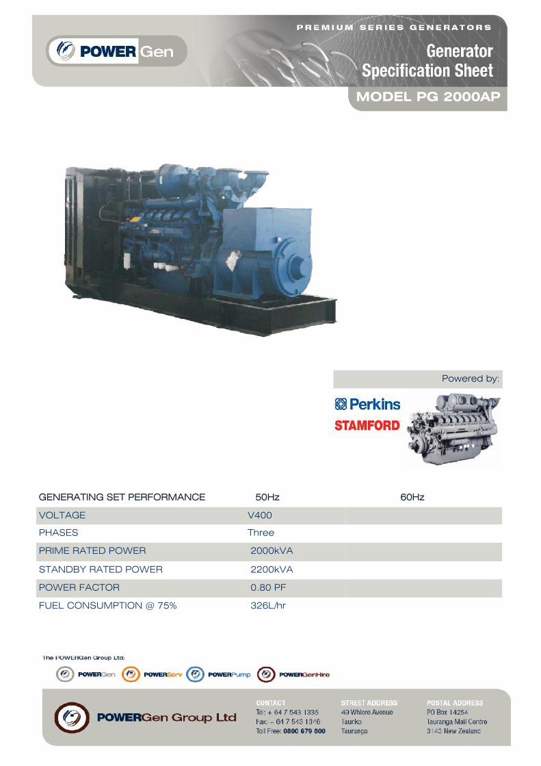
MODEL PG 2000AP
Powered by:
GENERATING SET PERFORMANCE 50Hz 60Hz
VOLTAGE V400
PHASES Three
PRIME RATED POWER 2000kVA
STANDBY RATED POWER 2200kVA
POWER FACTOR 0.80 PF
FUEL CONSUMPTION @ 75% 326L/hr
ENGINE PERKINS 4016-TAG2A
PERFORMANCE 50Hz 60Hz
BASELOAD RATED POWER 1362KWm
PRIME RATED POWER 1715KWm
STANDBY RATED POWER 1886KWm
FUEL CONSUMPTION 208g/KWh @ 100%207g/KWh @ 75%215g/KWh @ 50%
TYPE Diesel 4 stroke
ASPIRATION
INJECTION TYPE Direct injection
ENGINE GOVERNOR Electronic governing
CYLINDERS AND ARRANGEMENT 16 Vee
BORE x STROKE 160 x 190mm
COMPRESSION RATIO 13.6 : 1
ELECTRICAL SYSTEM VOLTAGE 24 volt
BATTERY TYPE Lead acid, 24V
DERATING FOR TEMPERATURE 40 deg C
DERATING FOR ALITITUDE 1000mm
DERATING FOR HUMIDITY 90%
Turbocharged and air to air charge cooled
ENGINE
ALTERNATOR STAMFORD
PERFORMANCE 50Hz 60Hz
MODEL LV 804 W
BASELOAD RATED POWER 40 deg C 3322kVA
PRIME RATED POWER 40 deg C 3555kVA
STANDBY RATED POWER 40 deg C 3800kVA
STANDBY RATED POWER 27 deg C 3910kVA
EFFICIENCY 96.5%
STANDARD WINDING CONNECTIONS Star Delta
EXCITER Separately excited by P.M.G
POLES 4 poles
PHASES 3 phases
WIRES 6 leads
VOLTAGE REGULATION +/- 0.5%
INSULATION CLASS Class H
ENCLOSURE IP23
MAXIMUM OVERSPEED 150%
STANDARD AVR MODEL MA330
OPTIONAL AVR MODEL TBA
DERATING FOR TEMPERATURE 40 deg C
DERATING FOR ALTITUDE 1000m
ALTERNATOR
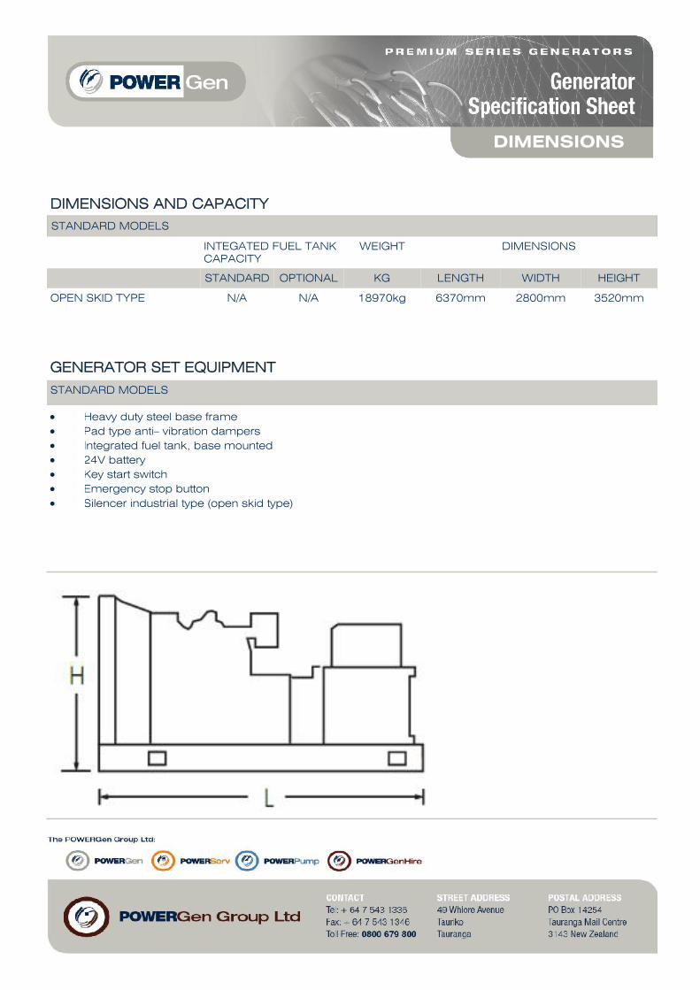
DIMENSIONS AND CAPACITY
STANDARD MODELS
INTEGATED FUEL TANKCAPACITY
WEIGHT DIMENSIONS
STANDARD OPTIONAL KG LENGTH WIDTH HEIGHT
OPEN SKID TYPE N/A N/A 18970kg 6370mm 2800mm 3520mm
GENERATOR SET EQUIPMENT
STANDARD MODELS
Heavy duty steel base frame Pad type anti– vibration dampers Integrated fuel tank, base mounted 24V battery Key start switch Emergency stop button Silencer industrial type (open skid type)
DIMENSIONS

AUTOMATIC MODELS– EQUIPMENT
4 poles 3200ABB circuit breaker, electronic control unit DeepSea 5320, control panel box key,emergency stop button, water jacket heaters,
AUTOMATIC MODELS– PROTECTORS
Low oil pressure, low fuel level, overload, over/ under frequency, unbalanced load, low voltage, over/under battery voltage belt breakage, charge alternator fail, Independent earth fault trip.
AUTOMATIC MODELS– INSTRUMENTATION
Voltmeter, ammeter (3 phases), frequency meter, hour meter, battery voltage meter, fuel level
CONTROLLER
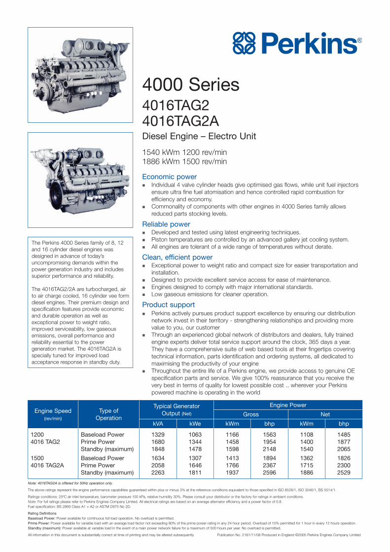
4000 Series4016TAG24016TAG2ADiesel Engine – Electro Unit
1540 kWm 1200 rev/min1886 kWm 1500 rev/min
Economic power� Individual 4 valve cylinder heads give optimised gas flows, while unit fuel injectors
ensure ultra fine fuel atomisation and hence controlled rapid combustion forefficiency and economy.
� Commonality of components with other engines in 4000 Series family allowsreduced parts stocking levels.
Reliable power� Developed and tested using latest engineering techniques.� Piston temperatures are controlled by an advanced gallery jet cooling system.� All engines are tolerant of a wide range of temperatures without derate.
Clean, efficient power� Exceptional power to weight ratio and compact size for easier transportation and
installation.� Designed to provide excellent service access for ease of maintenance.� Engines designed to comply with major international standards.� Low gaseous emissions for cleaner operation.
Product support� Perkins actively pursues product support excellence by ensuring our distribution
network invest in their territory - strengthening relationships and providing morevalue to you, our customer
� Through an experienced global network of distributors and dealers, fully trainedengine experts deliver total service support around the clock, 365 days a year.They have a comprehensive suite of web based tools at their fingertips coveringtechnical information, parts identification and ordering systems, all dedicated tomaximising the productivity of your engine
� Throughout the entire life of a Perkins engine, we provide access to genuine OEspecification parts and service. We give 100% reassurance that you receive thevery best in terms of quality for lowest possible cost .. wherever your Perkinspowered machine is operating in the world
The Perkins 4000 Series family of 8, 12and 16 cylinder diesel engines wasdesigned in advance of today’suncompromising demands within thepower generation industry and includessuperior performance and reliability.
The 4016TAG2/2A are turbocharged, airto air charge cooled, 16 cylinder vee formdiesel engines. Their premium design andspecification features provide economicand durable operation as well asexceptional power to weight ratio,improved serviceability, low gaseousemissions, overall performance andreliability essential to the powergeneration market. The 4016TAG2A isspecially tuned for improved loadacceptance response in standby duty.
Engine Speed(rev/min)
Type ofOperation
kVA kWe kWm bhp kWm bhp
Gross Net
Engine PowerTypical GeneratorOutput (Net)
1200 Baseload Power 1329 1063 1166 1563 1108 14854016 TAG2 Prime Power 1680 1344 1458 1954 1400 1877
Standby (maximum) 1848 1478 1598 2148 1540 2065
1500 Baseload Power 1634 1307 1413 1894 1362 18264016 TAG2A Prime Power 2058 1646 1766 2367 1715 2300
Standby (maximum) 2263 1811 1937 2596 1886 2529
Note: 4016TAG2A is offered for 50Hz operation only.
The above ratings represent the engine performance capabilities guaranteed within plus or minus 3% at the reference conditions equivalent to those specified in ISO 8528/1, ISO 3046/1, BS 5514/1.
Ratings conditions: 25ºC air inlet temperature, barometer pressure 100 kPa, relative humidity 30%. Please consult your distributor or the factory for ratings in ambient conditions.Note: For full ratings please refer to Perkins Engines Company Limited. All electrical ratings are based on an average alternator efficiency and a power factor of 0.8.Fuel specification: BS 2869 Class A1 + A2 or ASTM D975 No 2D.
Rating DefinitionsBaseload Power: Power available for continuous full load operation. No overload is permitted.Prime Power: Power available for variable load with an average load factor not exceeding 80% of the prime power rating in any 24 hour period. Overload of 10% permitted for 1 hour in every 12 hours operation.Standby (maximum): Power available at variable load in the event of a main power network failure for a maximum of 500 hours per year. No overload is permitted.
All information in this document is substantially correct at time of printing and may be altered subsequently Publication No. 2181/11/08 Produced in England ©2005 Perkins Engines Company Limited
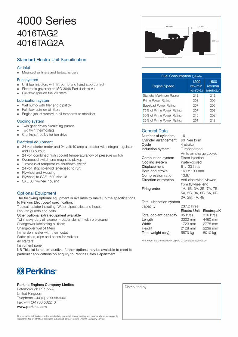
4460 mm
3827 mm
2775 mm
3239 mm
Perkins Engines Company LimitedPeterborough PE1 5NAUnited KingdomTelephone +44 (0)1733 583000Fax +44 (0)1733 582240www.perkins.com
All information in this document is substantially correct at time of printing and may be altered subsequentlyPublication No. 2181/11/08 Produced in England ©2005 Perkins Engines Company Limited
Standard Electro Unit Specification
Air inlet� Mounted air filters and turbochargers
Fuel system� Unit fuel injectors with lift pump and hand stop control� Electronic governor to ISO 3046 Part 4 class A1� Full-flow spin-on fuel oil filters
Lubrication system� Wet sump with filler and dipstick� Full-flow spin-on oil filters� Engine jacket water/lub oil temperature stabiliser
Cooling system� Twin gear driven circulating pumps� Two twin thermostats� Crankshaft pulley for fan drive
Electrical equipment� 24 volt starter motor and 24 volt/40 amp alternator with integral regulator
and DC output� 24 volt combined high coolant temperature/low oil pressure switch� Overspeed switch and magnetic pickup� Turbine inlet temperature shutdown switch� 24 volt stop solenoid (energised to run)� Flywheel and Housing� Flywheel to SAE J620 size 18� SAE 00 flywheel housing
Optional EquipmentThe following optional equipment is available to make up the specificationsto Perkins ElectropaK specification:Tropical radiator including: Water pipes, clips and hosesFan, fan guards and beltsOther optional extra equipment availableTwin heavy duty air cleaner – paper element with pre-cleanerChangeover lubricating oil filtersChangeover fuel oil filtersImmersion heater with thermostatWater pipes, clips and hoses for radiatorAir startersInstrument panelNB This list is not exhaustive, further options may be available to meet toparticular applications on enquiry to Perkins Sales Department
Distributed by
4000 Series4016TAG24016TAG2A
General DataNumber of cylinders 16Cylinder arrangement 60º Vee formCycle 4 strokeInduction system Turbocharged
Air to air charge cooledCombustion system Direct injectionCooling system Water-cooledDisplacement 61.123 litresBore and stroke 160 x 190 mmCompression ratio 13.6:1Direction of rotation Anti-clockwise, viewed
from flywheel endFiring order 1A, 1B, 3A, 3B, 7A, 7B,
5A, 5B, 8A, 8B, 6A, 6B,2A, 2B, 4A, 4B
Total lubrication systemcapacity 237.2 litres
Electro Unit ElectropaKTotal coolant capacity 95 litres 316 litresLength 3302 mm 4460 mmWidth 1723 mm 2775 mmHeight 2128 mm 3239 mmTotal weight (dry) 5570 kg 8010 kg
Final weight and dimensions will depend on completed specification
Standby Maximum Rating 212 212
Prime Power Rating 208 209
Baseload Power Rating 207 205
75% of Prime Power Rating 207 203
50% of Prime Power Rating 215 202
25% of Prime Power Rating 251 212
Fuel Consumption (g/kWh)
1200 1500Engine Speed rev/min rev/min
4016TAG2 4016TAG2A
��������Technical Data
Basic technical dataNumber of cylinders .. ... ... ... ... ... ... ... ... ... ... ... ... ... ... ... ... . 16Cylinder arrangement ... ... ... ... ... ... ... ... ... ... ... ... ... ... 60° VeeCycle . ... ... ... ... ... ... ... ... ... ... ... ..4 stroke, compression ignitionInduction system ... ... ... ... ... ... ... ... ... ... ... ... ... ...TurbochargedCompression ratio . ... ... ... ... ... ... ... ... ... ... ... ... ..13,6:1 nominalBore... ... ... ... ... ... ... ... ... ... ... ... ... ... ... ... ... ... ... ... ... 160 mmStroke ... ... ... ... ... ... ... ... ... ... ... ... ... ... ... ... ... ... ... ... 190 mmCubic capacity... ... ... ... ... ... ... ... ... ... ... ... ... ... ... ..61,123 litresDirection of rotation ... ... ... ... ... Anti-clockwise viewed on flywheelFiring order ... ... 1A,1B,3A,3B,7A,7B,5A,5B,8A,8B,6A,6B,2A,2B,4A,4B
Cylinders 1 are furthest from flywheel.Cylinders designated ‘A’ are on the left side of the engine when viewed from the front (opposite end to flywheel)Total weight Electrounit (engine only) ... ... ... ... ... ... (dry) 5570 kg.. ... ... ... ... ... ... ... ... ... ... ... ... ... ... ... ... ... ... ... ... (wet) 5847 kgOverall dimensions ... ... ... ... ... ... ... ... ... ... ... ...Height 2128 mm.. ... ... ... ... ... ... ... ... ... ... ... ... ... ... ... ... ... ... .. Length 3302 mm.. ... ... ... ... ... ... ... ... ... ... ... ... ... ... ... ... ... ... ... Width 1723 mmMoment of inertia .. ... ... ... ... ... ... ... ... ... ... ...Engine 11,15 kgm2
.. ... ... ... ... ... ... ... ... ... ... ... ... ... ... ... ... ... ..Flywheel 9,57 kgm2
Cyclic irregularity for engine/flywheel (Prime power):4016TAG1A ... 1500 rev/min. ... ... ... ... ... ... ... ... ... ... ... ... 1,3004016TAG2A ... 1500 rev/min. ... ... ... ... ... ... ... ... ... ... ... ... 1,277
RatingsSteady state speed stability at constant load . ... ... ... ... ...± 0,25%Electrical ratings are based on average alternator efficiency and are for guidance only (0,8 power factor being used).
Operating pointEngine speed . ... ... ... ... ... ... ... ... ... ... ... ... ... ... ... 1500 rev/minStatic injection timing.. ... ... ... ... ... ... ... ... ... ... ... ... ... see belowCooling water exit temp.. ... ... ... ... ... ... ... ... ... ... ... ... ... .<93 °C
Fuel dataTo conform to BS2869 class A1, A2.
PerformanceEstimated sound pressure level 1500 rev/min ... ... ... 106/112 dBANote: All data based on operation to ISO 3046/1, BS 5514 andDIN 6271 standard reference conditions.
Test conditions Air temperature... ... ... ... ... ... ... ... ... ... ... ... ... ... ... ... ... ...25 °CBarometric pressure ... ... ... ... ... ... ... ... ... ... ... ... ... ... ...100 kPaRelative humidity ... ... ... ... ... ... ... ... ... ... ... ... ... ... ... ... ... .30%Air inlet restriction at maximum power (nominal) ... ... ... ... 2,5 kPaExhaust back pressure (nominal)... ... ... ... ... ... ... ... ... ... 3,0 kPa
4000 Series4016TAG1A4016TAG2A
Emission compliant engines
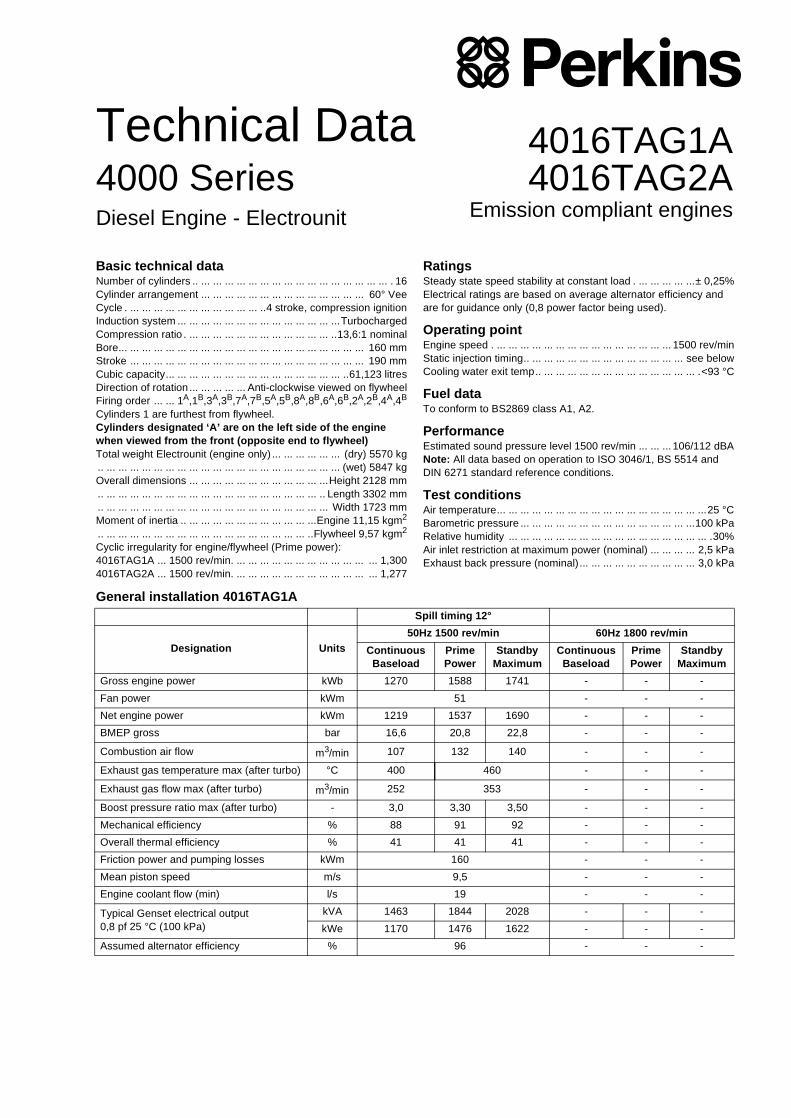
General installation 4016TAG1ASpill timing 12°
Designation Units50Hz 1500 rev/min 60Hz 1800 rev/min
Continuous Baseload
Prime Power
Standby Maximum
Continuous Baseload
Prime Power
Standby Maximum
Gross engine power kWb 1270 1588 1741 - - -
Fan power kWm 51 - - -
Net engine power kWm 1219 1537 1690 - - -
BMEP gross bar 16,6 20,8 22,8 - - -
Combustion air flow m3/min 107 132 140 - - -
Exhaust gas temperature max (after turbo) °C 400 460 - - -
Exhaust gas flow max (after turbo) m3/min 252 353 - - -
Boost pressure ratio max (after turbo) - 3,0 3,30 3,50 - - -
Mechanical efficiency % 88 91 92 - - -
Overall thermal efficiency % 41 41 41 - - -
Friction power and pumping losses kWm 160 - - -
Mean piston speed m/s 9,5 - - -
Engine coolant flow (min) l/s 19 - - -
Typical Genset electrical output0,8 pf 25 °C (100 kPa)
kVA 1463 1844 2028 - - -
kWe 1170 1476 1622 - - -
Assumed alternator efficiency % 96 - - -
Diesel Engine - Electrounit

General installation 4016TAG2A
Note: Not to be used for CHP design purposes. (Indicative figures only). Consult Perkins Engines Co. Ltd. Assumes complete combustion.
Continuous Baseload rating Power available for continuous full load operation. Prime Power rating is available for unlimited hours per year with a variable load of which the average engine load factor is 80% of the published prime power rating. Standby Power rating is for the supply of emergency power at variable load for the duration of the non-availability of the mains power supply. NO OVERLOAD capacity is available at this rating. Engines must not be allowed to have facilities for parallel operation with the mains supply. This rating should be applied only when reliable mains power is available. Should this not be the case then refer to Prime Power rating. A standby rated engine should be sized for an average load factor of 80% based on published standby rating for 500 operating hours per year. Standby ratings should never be applied except in true emergency power failure conditions.
On 16 cylinder engines used for baseload operation, the following items must be incorporated:1. Auto lubricating oil pump (extra price, see options).2. Centrifugal by-pass filter to be baseframe mounted (extra price, see options).3. Electrically driven radiators on separate baseframe (customer supply).4. Start/stop sequence as follows:
START - 4 minutes priming.2 minutes start and no load 1500 rev/min.Synchronise and ramp to full load over 3 minutes.
STOP - Ramp down to no load 1500 rev/min.5 minutes no load and running.Stop engine and run oil priming pump for 4 minutes.
Spill timing 14°
Designation Units50Hz 1500 rev/min 60Hz 1800 rev/min
Continuous Baseload
Prime Power
Standby Maximum
Continuous Baseload
Prime Power
Standby Maximum
Gross engine power kWb 1413 1766 1890 - - -
Fan power kWm 51 - - -
Net engine power kWm 1362 1715 1839 - - -
BMEP gross bar 18,5 23,1 25,4 - - -
Combustion air flow m3/min 117 137 145 - - -
Exhaust gas temperature max (after turbo) °C 450 493 - - -
Exhaust gas flow (max) m3/min 275 393 - -
Boost pressure ratio - 3,0 3,49 3,80 - - -
Mechanical efficiency % 88 92 92 - - -
Overall electrical efficiency % 41 40 40 - - -
Friction power and pumping losses kWm 160 - - -
Mean piston speed m/s 9,5 - -
Engine coolant flow (min) l/s 19 - -
Typical Genset electrical output0,8 pf 25 °C (100 kPa)
kVA 1634 2058 2206 - - -
kWe 1307 1646 1765 - - -
Assumed alternator efficiency % 96 - - -
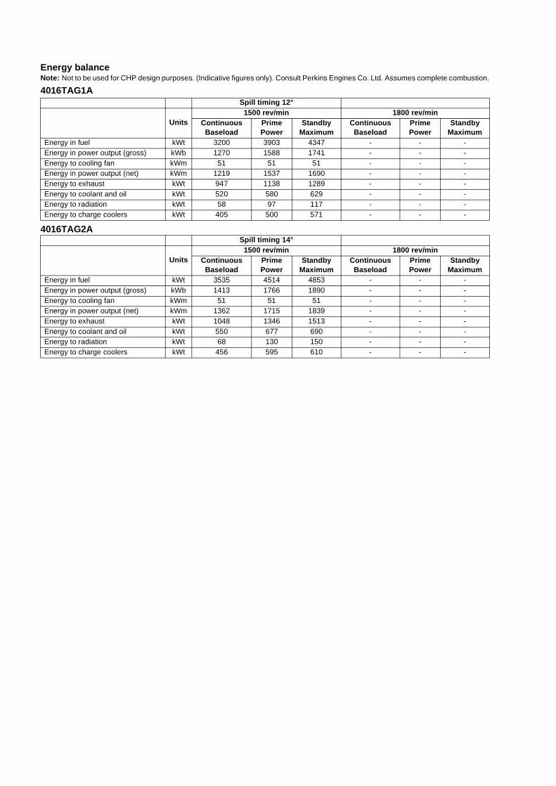
Energy balanceNote: Not to be used for CHP design purposes. (Indicative figures only). Consult Perkins Engines Co. Ltd. Assumes complete combustion.
4016TAG1A
4016TAG2A
Spill timing 12°
Units1500 rev/min 1800 rev/min
Continuous Baseload
Prime Power
Standby Maximum
Continuous Baseload
Prime Power
Standby Maximum
Energy in fuel kWt 3200 3903 4347 - - -Energy in power output (gross) kWb 1270 1588 1741 - - -Energy to cooling fan kWm 51 51 51 - - -Energy in power output (net) kWm 1219 1537 1690 - - -Energy to exhaust kWt 947 1138 1289 - - -Energy to coolant and oil kWt 520 580 629 - - -Energy to radiation kWt 58 97 117 - - -Energy to charge coolers kWt 405 500 571 - - -
Spill timing 14°
Units1500 rev/min 1800 rev/min
Continuous Baseload
Prime Power
Standby Maximum
Continuous Baseload
Prime Power
Standby Maximum
Energy in fuel kWt 3535 4514 4853 - - -Energy in power output (gross) kWb 1413 1766 1890 - - -Energy to cooling fan kWm 51 51 51 - - -Energy in power output (net) kWm 1362 1715 1839 - - -Energy to exhaust kWt 1048 1346 1513 - - -Energy to coolant and oil kWt 550 677 690 - - -Energy to radiation kWt 68 130 150 - - -Energy to charge coolers kWt 456 595 610 - - -
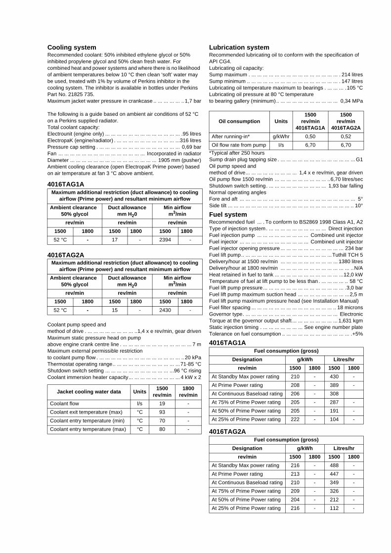
Cooling systemRecommended coolant: 50% inhibited ethylene glycol or 50% inhibited propylene glycol and 50% clean fresh water. For combined heat and power systems and where there is no likelihood of ambient temperatures below 10 °C then clean ‘soft’ water may be used, treated with 1% by volume of Perkins inhibitor in the cooling system. The inhibitor is available in bottles under Perkins Part No. 21825 735.Maximum jacket water pressure in crankcase .. ... ... ... ... .. 1,7 bar
The following is a guide based on ambient air conditions of 52 °C on a Perkins supplied radiator.Total coolant capacity:Electrounit (engine only) ... ... ... ... ... ... ... ... ... ... ... ... ... .95 litresElectropaK (engine/radiator) . ... ... ... ... ... ... ... ... ... ... ...316 litresPressure cap setting . ... ... ... ... ... ... ... ... ... ... ... ... ... ... 0,69 barFan ... ... ... ... ... ... ... ... ... ... ... ... ... ... ... Incorporated in radiatorDiameter ... ... ... ... ... ... ... ... ... ... ... ... ... ... ... 1905 mm (pusher)Ambient cooling clearance (open ElectropaK Prime power) based on air temperature at fan 3 °C above ambient.
4016TAG1A
4016TAG2A
Coolant pump speed and method of drive . ... ... ... ... ... ... ... ... ..1,4 x e rev/min, gear drivenMaximum static pressure head on pump above engine crank centre line . ... ... ... ... ... ... ... ... ... ... ... ... 7 mMaximum external permissible restriction to coolant pump flow . ... ... ... ... ... ... ... ... ... ... ... ... ... ... .. 20 kPaThermostat operating range.. ... ... ... ... ... ... ... ... ... ... ...71-85 °CShutdown switch setting ... ... ... ... ... ... ... ... ... ... ... ...96 °C risingCoolant immersion heater capacity... ... ... ... ... ... ... ... ... 4 kW x 2
Lubrication systemRecommended lubricating oil to conform with the specification of API CG4.Lubricating oil capacity:Sump maximum . ... ... ... ... ... ... ... ... ... ... ... ... ... ... ... . 214 litresSump minimum .. ... ... ... ... ... ... ... ... ... ... ... ... ... ... ... . 147 litresLubricating oil temperature maximum to bearings . ... ... ... .105 °CLubricating oil pressure at 80 °C temperatureto bearing gallery (minimum).. ... ... ... ... ... ... ... ... ... ... 0,34 MPa
*Typical after 250 hoursSump drain plug tapping size . ... ... ... ... ... ... ... ... ... ... ... ... ... G1Oil pump speed andmethod of drive... ... ... ... ... ... ... ... ... 1,4 x e rev/min, gear drivenOil pump flow 1500 rev/min ... ... ... ... ... ... ... ... ... ..6,70 litres/secShutdown switch setting. ... ... ... ... ... ... ... ... ... ... 1,93 bar fallingNormal operating anglesFore and aft ... ... ... ... ... ... ... ... ... ... ... ... ... ... ... ... ... ... ... ... 5°Side tilt ... ... ... ... ... ... ... ... ... ... ... ... ... ... ... ... ... ... ... ... ... .. 10°
Fuel systemRecommended fuel ... . To conform to BS2869 1998 Class A1, A2Type of injection system. ... ... ... ... ... ... ... ... ... ... Direct injectionFuel injection pump ... ... ... ... ... ... ... ... ... Combined unit injectorFuel injector ... ... ... ... ... ... ... ... ... ... ... ... Combined unit injectorFuel injector opening pressure ... ... ... ... ... ... ... ... ... ... ... 234 barFuel lift pump.. ... ... ... ... ... ... ... ... ... ... ... ... ... ... ...Tuthill TCH 5Delivery/hour at 1500 rev/min ... ... ... ... ... ... ... ... ... ... 1380 litresDelivery/hour at 1800 rev/min ... ... ... ... ... ... ... ... ... ... ... ... ..N/AHeat retained in fuel to tank ... ... ... ... ... ... ... ... ... ... ... ...12,0 kWTemperature of fuel at lift pump to be less than . ... ... ... ... .. 58 °CFuel lift pump pressure... ... ... ... ... ... ... ... ... ... ... ... ... ... .3,0 barFuel lift pump maximum suction head ... ... ... ... ... ... ... ... ...2,5 mFuel lift pump maximum pressure head (see Installation Manual)Fuel filter spacing ... ... ... ... ... ... ... ... ... ... ... ... ... ... .. 18 micronsGovernor type. ... ... ... ... ... ... ... ... ... ... ... ... ... ... ... ... ElectronicTorque at the governor output shaft ... ... ... ... ... ... ... ... 1,631 kgmStatic injection timing . ... ... ... ... ... ... ... See engine number plateTolerance on fuel consumption .. ... ... ... ... ... ... ... ... ... ... ... .+5%
4016TAG1A
4016TAG2A
Maximum additional restriction (duct allowance) to cooling airflow (Prime power) and resultant minimum airflow
Ambient clearance50% glycol
Duct allowancemm H20
Min airflowm3/min
rev/min rev/min rev/min
1500 1800 1500 1800 1500 1800
52 °C - 17 - 2394 -
Maximum additional restriction (duct allowance) to cooling airflow (Prime power) and resultant minimum airflow
Ambient clearance50% glycol
Duct allowancemm H20
Min airflowm3/min
rev/min rev/min rev/min
1500 1800 1500 1800 1500 1800
52 °C - 15 - 2430 -
Jacket cooling water data Units1500
rev/min1800
rev/min
Coolant flow l/s 19 -
Coolant exit temperature (max) °C 93 -
Coolant entry temperature (min) °C 70 -
Coolant entry temperature (max) °C 80 -
Oil consumption Units1500
rev/min4016TAG1A
1500rev/min
4016TAG2A
After running-in* g/kWhr 0,50 0,52
Oil flow rate from pump I/s 6,70 6,70
Fuel consumption (gross)
Designation g/kWh Litres/hr
rev/min 1500 1800 1500 1800
At Standby Max power rating 210 - 430 -
At Prime Power rating 208 - 389 -
At Continuous Baseload rating 206 - 308
At 75% of Prime Power rating 205 - 287 -
At 50% of Prime Power rating 205 - 191 -
At 25% of Prime Power rating 222 - 104 -
Fuel consumption (gross)
Designation g/kWh Litres/hr
rev/min 1500 1800 1500 1800
At Standby Max power rating 216 - 488 -
At Prime Power rating 213 - 447 -
At Continuous Baseload rating 210 - 349 -
At 75% of Prime Power rating 209 - 326 -
At 50% of Prime Power rating 204 - 212 -
At 25% of Prime Power rating 216 - 112 -
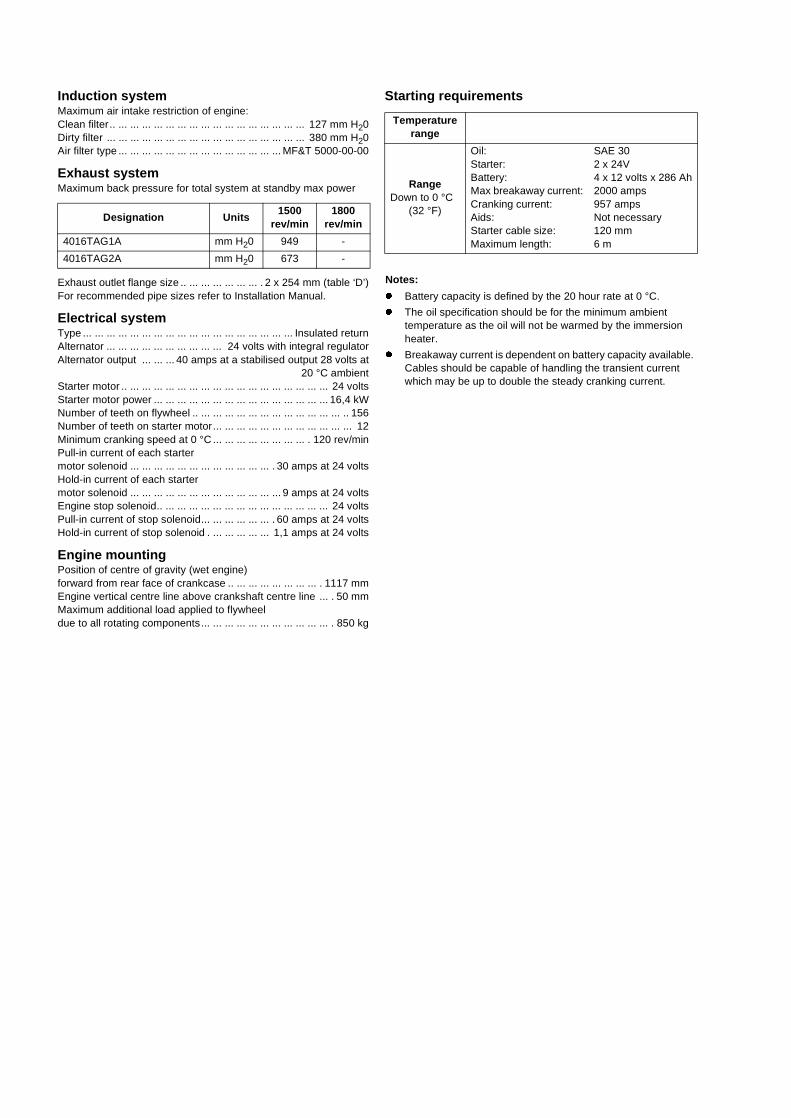
Induction systemMaximum air intake restriction of engine:Clean filter.. ... ... ... ... ... ... ... ... ... ... ... ... ... ... ... ... 127 mm H20Dirty filter ... ... ... ... ... ... ... ... ... ... ... ... ... ... ... ... ... 380 mm H20Air filter type ... ... ... ... ... ... ... ... ... ... ... ... ... ... MF&T 5000-00-00
Exhaust systemMaximum back pressure for total system at standby max power
Exhaust outlet flange size .. ... ... ... ... ... ... . 2 x 254 mm (table ‘D’)For recommended pipe sizes refer to Installation Manual.
Electrical systemType ... ... ... ... ... ... ... ... ... ... ... ... ... ... ... ... ... ... Insulated returnAlternator ... ... ... ... ... ... ... ... ... ... 24 volts with integral regulatorAlternator output ... ... ... 40 amps at a stabilised output 28 volts at
20 °C ambientStarter motor .. ... ... ... ... ... ... ... ... ... ... ... ... ... ... ... ... ... 24 voltsStarter motor power ... ... ... ... ... ... ... ... ... ... ... ... ... ... ... 16,4 kWNumber of teeth on flywheel .. ... ... ... ... ... ... ... ... ... ... ... ... .. 156Number of teeth on starter motor... ... ... ... ... ... ... ... ... ... ... ... 12Minimum cranking speed at 0 °C ... ... ... ... ... ... ... ... . 120 rev/minPull-in current of each starter motor solenoid ... ... ... ... ... ... ... ... ... ... ... ... . 30 amps at 24 voltsHold-in current of each starter motor solenoid ... ... ... ... ... ... ... ... ... ... ... ... ... 9 amps at 24 voltsEngine stop solenoid.. ... ... ... ... ... ... ... ... ... ... ... ... ... ... 24 voltsPull-in current of stop solenoid... ... ... ... ... ... . 60 amps at 24 voltsHold-in current of stop solenoid . ... ... ... ... ... 1,1 amps at 24 volts
Engine mountingPosition of centre of gravity (wet engine) forward from rear face of crankcase .. ... ... ... ... ... ... ... . 1117 mmEngine vertical centre line above crankshaft centre line ... . 50 mmMaximum additional load applied to flywheeldue to all rotating components... ... ... ... ... ... ... ... ... ... ... . 850 kg
Starting requirements
Notes:
� Battery capacity is defined by the 20 hour rate at 0 °C.
� The oil specification should be for the minimum ambient temperature as the oil will not be warmed by the immersion heater.
� Breakaway current is dependent on battery capacity available. Cables should be capable of handling the transient current which may be up to double the steady cranking current.
Designation Units1500
rev/min1800
rev/min
4016TAG1A mm H20 949 -
4016TAG2A mm H20 673 -
Temperature range
RangeDown to 0 °C
(32 °F)
Oil:Starter:Battery:Max breakaway current:Cranking current:Aids:Starter cable size:Maximum length:
SAE 302 x 24V4 x 12 volts x 286 Ah2000 amps957 ampsNot necessary120 mm6 m
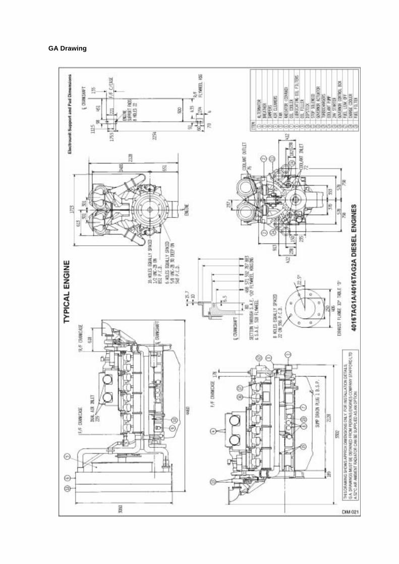
GA Drawing
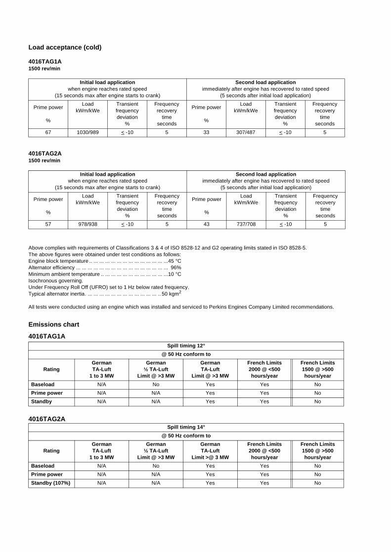
Load acceptance (cold)
4016TAG1A 1500 rev/min
4016TAG2A1500 rev/min
Above complies with requirements of Classifications 3 & 4 of ISO 8528-12 and G2 operating limits stated in ISO 8528-5.The above figures were obtained under test conditions as follows:Engine block temperature .. ... ... ... ... ... ... ... ... ... ... ... ... ...45 °CAlternator efficiency ... ... ... ... ... ... ... ... ... ... ... ... ... ... ... ... 96%Minimum ambient temperature .. ... ... ... ... ... ... ... ... ... ... ...10 °CIsochronous governing.Under Frequency Roll Off (UFRO) set to 1 Hz below rated frequency.Typical alternator inertia. ... ... ... ... ... ... ... ... ... ... ... ... .. 50 kgm2
All tests were conducted using an engine which was installed and serviced to Perkins Engines Company Limited recommendations.
Emissions chart
4016TAG1A
4016TAG2A
Initial load applicationwhen engine reaches rated speed
(15 seconds max after engine starts to crank)
Second load applicationimmediately after engine has recovered to rated speed
(5 seconds after initial load application)
Prime power
%
LoadkWm/kWe
Transientfrequencydeviation
%
Frequencyrecovery
time seconds
Prime power
%
LoadkWm/kWe
Transientfrequency deviation
%
Frequencyrecovery
timeseconds
67 1030/989 < -10 5 33 307/487 < -10 5
Initial load applicationwhen engine reaches rated speed
(15 seconds max after engine starts to crank)
Second load applicationimmediately after engine has recovered to rated speed
(5 seconds after initial load application)
Prime power
%
LoadkWm/kWe
Transientfrequencydeviation
%
Frequencyrecovery
time seconds
Prime power
%
LoadkWm/kWe
Transientfrequency deviation
%
Frequencyrecovery
timeseconds
57 978/938 < -10 5 43 737/708 < -10 5
Spill timing 12°
@ 50 Hz conform to
RatingGermanTA-Luft
1 to 3 MW
German½ TA-Luft
Limit @ >3 MW
GermanTA-Luft
Limit @ >3 MW
French Limits2000 @ <500hours/year
French Limits1500 @ >500hours/year
Baseload N/A No Yes Yes No
Prime power N/A N/A Yes Yes No
Standby N/A N/A Yes Yes No
Spill timing 14°
@ 50 Hz conform to
RatingGermanTA-Luft
1 to 3 MW
German½ TA-Luft
Limit @ >3 MW
GermanTA-Luft
Limit >@ 3 MW
French Limits2000 @ <500hours/year
French Limits1500 @ >500hours/year
Baseload N/A No Yes Yes No
Prime power N/A N/A Yes Yes No
Standby (107%) N/A N/A Yes Yes No
��������
All information in the document is substantially correct at the time of printing but may be subsequently altered by the company.
Distributed by
4000 Series Emission compliant engines
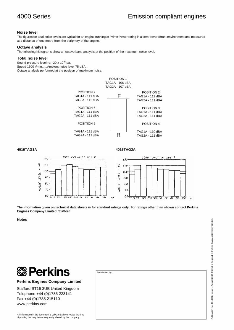
Noise levelThe figures for total noise levels are typical for an engine running at Prime Power rating in a semi-reverberant environment and measured at a distance of one metre from the periphery of the engine.
Octave analysisThe following histograms show an octave band analysis at the position of the maximum noise level.
Total noise levelSound pressure level re: -20 x 10-6 pa.Speed 1500 r/min......Ambient noise level 75 dBA.Octave analysis performed at the position of maximum noise.
4016TAG1A 4016TAG2A
The information given on technical data sheets is for standard ratings only. For ratings other than shown contact Perkins Engines Company Limited, Stafford.
Notes
POSITION 7TAG1A - 111 dBATAG2A - 112 dBA
POSITION 6TAG1A - 111 dBATAG2A - 111 dBA
POSITION 5
TAG1A - 111 dBATAG2A - 111 dBA
POSITION 1TAG1A - 106 dBATAG2A - 107 dBA
POSITION 2TAG1A - 112 dBATAG2A - 111 dBA
POSITION 3TAG1A - 111 dBATAG2A - 111 dBA
POSITION 4
TAG1A - 110 dBATAG2A - 111 dBA
F
R
Pub
licat
ion
No.
TS
L425
8, Is
sue
1, A
ugus
t 200
2. P
rinte
d in
Eng
land
. © P
erki
ns E
ngin
es C
ompa
ny L
imite
d.
Perkins Engines Company Limited
Stafford ST16 3UB United KingdomTelephone +44 (0)1785 223141Fax +44 (0)1785 215110www.perkins.com
WDG 12 - Technical Data SheetLV 804 W
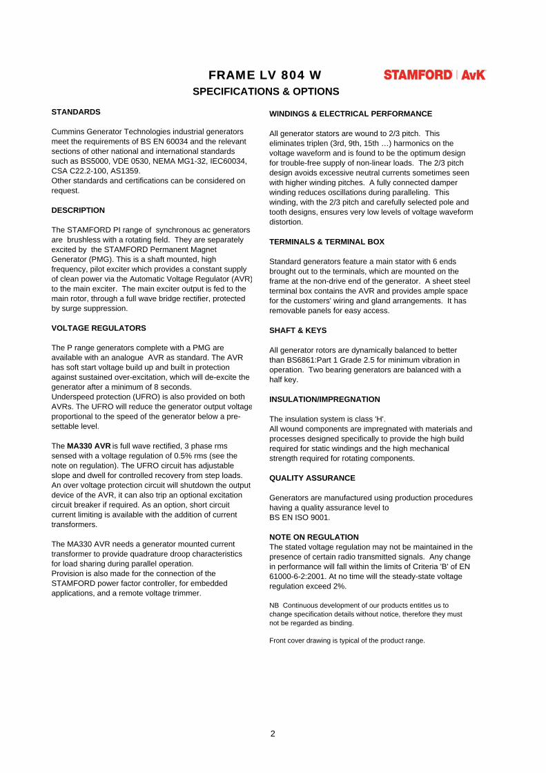
FRAME LV 804 WSPECIFICATIONS & OPTIONS
STANDARDS
Cummins Generator Technologies industrial generators meet the requirements of BS EN 60034 and the relevant sections of other national and international standards such as BS5000, VDE 0530, NEMA MG1-32, IEC60034, CSA C22.2-100, AS1359.Other standards and certifications can be considered on request.
DESCRIPTION
The STAMFORD PI range of synchronous ac generators are brushless with a rotating field. They are separately excited by the STAMFORD Permanent Magnet Generator (PMG). This is a shaft mounted, high frequency, pilot exciter which provides a constant supply of clean power via the Automatic Voltage Regulator (AVR)to the main exciter. The main exciter output is fed to the main rotor, through a full wave bridge rectifier, protected by surge suppression. VOLTAGE REGULATORS
The P range generators complete with a PMG are available with an analogue AVR as standard. The AVR has soft start voltage build up and built in protection against sustained over-excitation, which will de-excite the generator after a minimum of 8 seconds. Underspeed protection (UFRO) is also provided on both AVRs. The UFRO will reduce the generator output voltageproportional to the speed of the generator below a pre-settable level.
The MA330 AVR is full wave rectified, 3 phase rms sensed with a voltage regulation of 0.5% rms (see the note on regulation). The UFRO circuit has adjustable slope and dwell for controlled recovery from step loads. An over voltage protection circuit will shutdown the output device of the AVR, it can also trip an optional excitation circuit breaker if required. As an option, short circuit current limiting is available with the addition of current transformers.
The MA330 AVR needs a generator mounted current transformer to provide quadrature droop characteristics for load sharing during parallel operation. Provision is also made for the connection of the STAMFORD power factor controller, for embedded applications, and a remote voltage trimmer.
WINDINGS & ELECTRICAL PERFORMANCE
All generator stators are wound to 2/3 pitch. This eliminates triplen (3rd, 9th, 15th …) harmonics on the voltage waveform and is found to be the optimum design for trouble-free supply of non-linear loads. The 2/3 pitch design avoids excessive neutral currents sometimes seen with higher winding pitches. A fully connected damper winding reduces oscillations during paralleling. This winding, with the 2/3 pitch and carefully selected pole and tooth designs, ensures very low levels of voltage waveform distortion.
TERMINALS & TERMINAL BOX
Standard generators feature a main stator with 6 ends brought out to the terminals, which are mounted on the frame at the non-drive end of the generator. A sheet steel terminal box contains the AVR and provides ample space for the customers' wiring and gland arrangements. It has removable panels for easy access.
SHAFT & KEYS
All generator rotors are dynamically balanced to better than BS6861:Part 1 Grade 2.5 for minimum vibration in operation. Two bearing generators are balanced with a half key.
INSULATION/IMPREGNATION
The insulation system is class 'H'.All wound components are impregnated with materials and processes designed specifically to provide the high build required for static windings and the high mechanical strength required for rotating components.
QUALITY ASSURANCE
Generators are manufactured using production procedures having a quality assurance level to BS EN ISO 9001.
NOTE ON REGULATIONThe stated voltage regulation may not be maintained in the presence of certain radio transmitted signals. Any change in performance will fall within the limits of Criteria 'B' of EN 61000-6-2:2001. At no time will the steady-state voltage regulation exceed 2%.
NB Continuous development of our products entitles us to change specification details without notice, therefore they must not be regarded as binding.
Front cover drawing is typical of the product range.
2
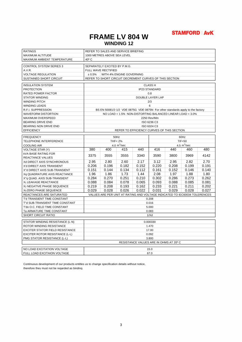
FRAME LV 804 W
RATINGS REFER TO SALES AND SERVICE BRIEFING MAXIMUM ALTITUDE 1000 METRES ABOVE SEA LEVEL MAXIMUM AMBIENT TEMPERATURE 40º C
CONTROL SYSTEM SERIES 3 SEPARATELY EXCITED BY P.M.G. A.V.R. FULL WAVE RECTIFIED VOLTAGE REGULATION ± 0.5% WITH 4% ENGINE GOVERNING SUSTAINED SHORT CIRCUIT REFER TO SHORT CIRCUIT DECREMENT CURVES OF THIS SECTION
INSULATION SYSTEM CLASS H PROTECTION IP23 STANDARD RATED POWER FACTOR 0.8 STATOR WINDING DOUBLE LAYER LAP WINDING PITCH 2/3 WINDING LEADS 6 R.F.I. SUPPRESSION BS EN 50081/2-1/2 VDE 0875G VDE 0875N For other standards apply to the factory WAVEFORM DISTORTION NO LOAD < 1.5% NON-DISTORTING BALANCED LINEAR LOAD < 3.0% MAXIMUM OVERSPEED 2250 Rev/Min BEARING DRIVE END ISO 6236 C3 BEARING NON DRIVE END ISO 6324 C3 EFFICIENCY REFER TO EFFICIENCY CURVES OF THIS SECTION
FREQUENCY 50Hz 60Hz TELEPHONE INTERFERENCE THF< 2% TIF<50 COOLING AIR m3/sec m3/sec VOLTAGE STAR (Y) 380 400 415 440 416 440 460 480 kVA BASE RATING FOR REACTANCE VALUES Xd DIRECT AXIS SYNCHRONOUS 2.95 2.80 2.60 2.17 3.12 2.95 2.82 2.70 X'd DIRECT AXIS TRANSIENT 0.206 0.196 0.182 0.152 0.220 0.208 0.199 0.191 X''d DIRECT AXIS SUB-TRANSIENT 0.151 0.144 0.134 0.112 0.161 0.152 0.146 0.140 Xq QUADRATURE AXIS REACTANCE 1.96 1.86 1.73 1.44 2.08 1.97 1.88 1.80 X''q QUAD. AXIS SUB-TRANSIENT 0.284 0.270 0.251 0.210 0.302 0.286 0.273 0.262 XL LEAKAGE REACTANCE 0.088 0.084 0.078 0.065 0.093 0.088 0.085 0.081 X2 NEGATIVE PHASE SEQUENCE 0.219 0.208 0.193 0.162 0.233 0.221 0.211 0.202 X0 ZERO PHASE SEQUENCE 0.029 0.028 0.026 0.022 0.031 0.029 0.028 0.027 REACTANCES ARE SATURATED T'd TRANSIENT TIME CONSTANT T''d SUB-TRANSIENT TIME CONSTANT T'do O.C. FIELD TIME CONSTANT Ta ARMATURE TIME CONSTANT SHORT CIRCUIT RATIO 1/Xd STATOR WINDING RESISTANCE (L-N) ROTOR WINDING RESISTANCE EXCITER STATOR FIELD RESISTANCE EXCITER ROTOR RESISTANCE (L-L) PMG STATOR RESISTANCE (L-L)
RESISTANCE VALUES ARE IN OHMS AT 20º C
NO LOAD EXCITATION VOLTAGE 15.0 FULL LOAD EXCITAION VOLTAGE 67.0
WINDING 12
3340
VALUES ARE PER UNIT AT RATING AND VOLTAGE INDICATED TO IEC60034 TOLERENCES
4.0 4.5
3800 3969 4142
3.800
0.0165.0000.083
0.0003301.47017.000.092
0.208
35903375 3555 3555
Continuous development of our products entitles us to change specification details without notice,therefore they must not be regarded as binding.
3
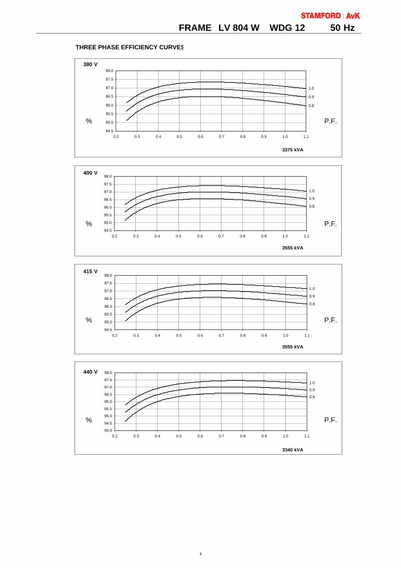
FRAME LV 804 W WDG 12 50 Hz
THREE PHASE EFFICIENCY CURVES
380 V
% P.F.
3375.0 kVA3375 kVA
400 V
% P.F.
3555 kVA
415 V
% P.F.
3555 kVA
440 V
% P.F.
3340 kVA
0.8
0.9
1.0
94.5
95.0
95.5
96.0
96.5
97.0
97.5
98.0
0.2 0.3 0.4 0.5 0.6 0.7 0.8 0.9 1.0 1.1
0.8
0.9
1.0
94.5
95.0
95.5
96.0
96.5
97.0
97.5
98.0
0.2 0.3 0.4 0.5 0.6 0.7 0.8 0.9 1.0 1.1
0.8
0.9
1.0
94.5
95.0
95.5
96.0
96.5
97.0
97.5
98.0
0.2 0.3 0.4 0.5 0.6 0.7 0.8 0.9 1.0 1.1
0.8
0.9
1.0
94.0
94.5
95.0
95.5
96.0
96.5
97.0
97.5
98.0
0.2 0.3 0.4 0.5 0.6 0.7 0.8 0.9 1.0 1.1
4
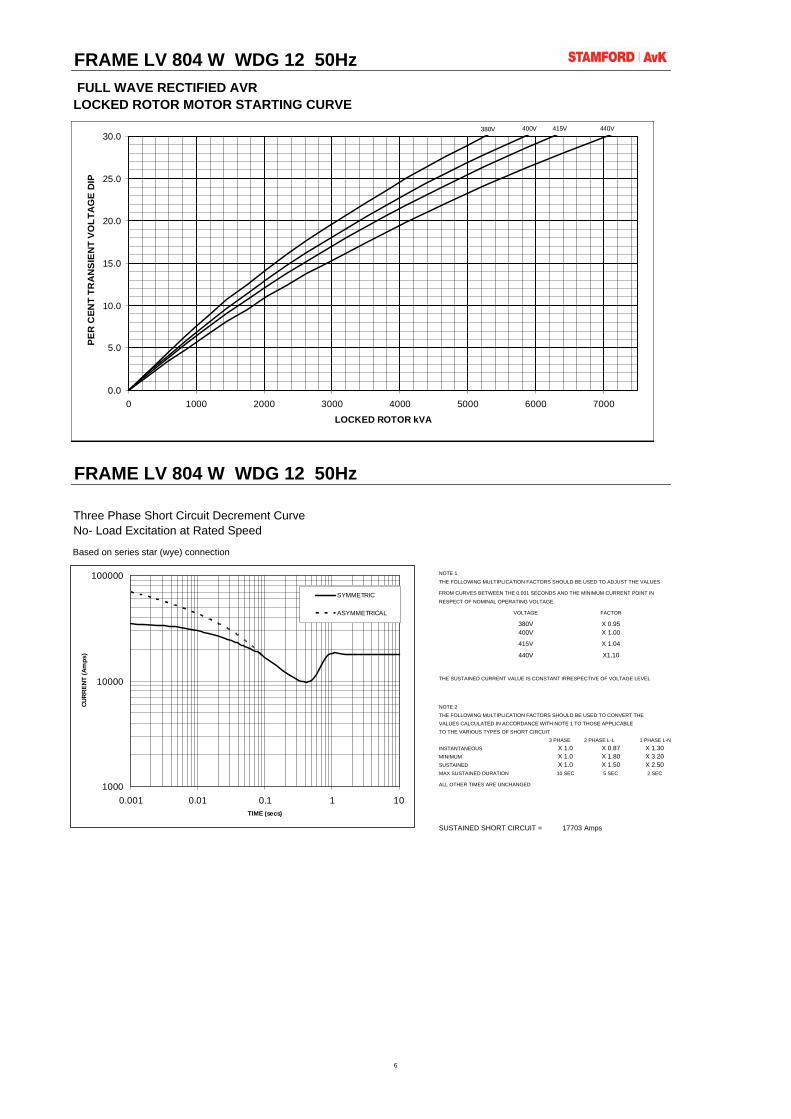
FRAME LV 804 W WDG 12 50Hz FULL WAVE RECTIFIED AVRLOCKED ROTOR MOTOR STARTING CURVE
FRAME LV 804 W WDG 12 50Hz
Three Phase Short Circuit Decrement CurveNo- Load Excitation at Rated Speed
Based on series star (wye) connection
NOTE 1
THE FOLLOWING MULTIPLICATION FACTORS SHOULD BE USED TO ADJUST THE VALUES
FROM CURVES BETWEEN THE 0.001 SECONDS AND THE MINIMUM CURRENT POINT IN
RESPECT OF NOMINAL OPERATING VOLTAGE
VOLTAGE FACTOR
380V X 0.95400V X 1.00
415V X 1.04
440V X1.10
THE SUSTAINED CURRENT VALUE IS CONSTANT IRRESPECTIVE OF VOLTAGE LEVEL
NOTE 2THE FOLLOWING MULTIPLICATION FACTORS SHOULD BE USED TO CONVERT THEVALUES CALCULATED IN ACCORDANCE WITH NOTE 1 TO THOSE APPLICABLETO THE VARIOUS TYPES OF SHORT CIRCUIT
3 PHASE 2 PHASE L-L 1 PHASE L-NINSTANTANEOUS X 1.0 X 0.87 X 1.30MINIMUM X 1.0 X 1.80 X 3.20SUSTAINED X 1.0 X 1.50 X 2.50MAX SUSTAINED DURATION 10 SEC 5 SEC 2 SEC
ALL OTHER TIMES ARE UNCHANGED
SUSTAINED SHORT CIRCUIT = 17703 Amps
1000
10000
100000
0.001 0.01 0.1 1 10TIME (secs)
CUR
REN
T (A
mps
)
SYMMETRIC
ASYMMETRICAL
380V 400V 415V 440V
0.0
5.0
10.0
15.0
20.0
25.0
30.0
0 1000 2000 3000 4000 5000 6000 7000
LOCKED ROTOR kVA
PER
CEN
T TR
AN
SIEN
T VO
LTA
GE
DIP
6
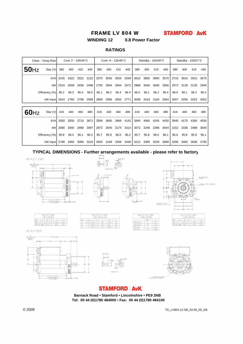
Class - Temp Rise
Star (V) 380 400 415 440 380 400 415 440 380 400 415 440 380 400 415 440
kVA 3155 3322 3322 3122 3375 3555 3555 3340 3610 3800 3800 3570 3715 3910 3910 3675
kW 2524 2658 2658 2498 2700 2844 2844 2672 2888 3040 3040 2856 2972 3128 3128 2940
Efficiency (%) 96.2 96.3 96.4 96.5 96.1 96.2 96.3 96.4 96.0 96.1 96.2 96.4 96.0 96.1 96.2 96.3
kW Input 2624 2760 2758 2589 2809 2956 2953 2771 3008 3163 3160 2964 3097 3256 3252 3052
Star (V) 416 440 460 480 416 440 460 480 416 440 460 480 416 440 460 480
kVA 3350 3550 3710 3871 3590 3800 3969 4142 3840 4060 4245 4430 3940 4170 4360 4550
kW 2680 2840 2968 3097 2872 3040 3175 3314 3072 3248 3396 3544 3152 3336 3488 3640
Efficiency (%) 95.8 96.0 96.1 96.2 95.7 95.9 96.0 96.2 95.7 95.8 96.0 96.1 95.6 95.8 95.9 96.1
kW Input 2798 2960 3089 3219 3000 3169 3306 3446 3212 3389 3539 3689 3296 3482 3636 3790
© 2009 TD_LV804.12.GB_03.09_09_GB
WINDING 12
TYPICAL DIMENSIONS - Further arrangements available - please refer to factory
FRAME LV 804 W 0.8 Power Factor
RATINGS
Cont. F - 105/40°C Cont. H - 125/40°C Standby - 150/40°C Standby - 163/27°C
50Hz
60Hz
50Hz
60Hz
Barnack Road • Stamford • Lincolnshire • PE9 2NBTel: 00 44 (0)1780 484000 • Fax: 00 44 (0)1780 484100

®DSECONTROL®
MONITORINGWITHINTELLIGENCE.
The DSE7310 and DSE7320 are newcontrol modules for single gen-setapplications. The modules havebeen developed from the successfulDSE5310 and DSE5320 Series andincorporate a number of advancedfeatures to meet the mostdemanding on-site applications.
The DSE7310 is an Automatic StartControl Module and the DSE7320 isanAutoMains (Utility) FailureControlModule. Both modules have beendesigned to start and stopdiesel andgas generating sets that includeelectronic and non-electronicengines. TheDSE7320 includes theadditional capability of being able tomonitor a mains (utility) supply.
Both modules include USB, RS232and RS485 ports as well asdedicated DSENet® terminals forexpansion device connectivity.
The modules are simple to operateand feature a newly designedmenu layout for improved clarity.Enhanced features include a realtime clock for enhanced event andperformance monitoring, ethernetcommunications for low costmonitoring, mutual standby toreduce engine wear and tear, trendanalysis to assist in the detectionof patterns in engine status andpreventative maintenancedesigned to detect if engine partshave developed fault conditions sothey can be replaced before amajor problem occurs.
FEATURES• Backed up real time clock• 132 x 64 pixel LCD display• Configurable display languages• USB connectivity• Robust module enclosure• Five-key menu navigation• Durable soft touch membranebuttons
• Fully configurable via PC software• LED and LCD alarm indication• Engine exercise mode• Configurable start & fuel outputs• kWh monitoring• Automatic load transfer• Eight configurable digital inputs• Six configurable outputs• Configurable timers and alarms• Modbus RTU• Magnetic pick-up• Front panel programming• Multiple date and time exercisescheduler
• SMS messaging• Power save mode• PIN protected programming• User selectable RS232 & RS485communications
• DSENet® compatible• Ethernet communications viaDSE860/865
• Customer logo display capability• Multiple date and timemaintenance scheduler
• Configurable display pages• Programmable loadshedding/acceptance
• Trend analysis• Preventative maintenance• kW overload protection• Unbalanced load protection• PDA compatible PC software
• Flexible sender input• Configurable SCADA output page
NEWFEATURES• True dual mutual standby withload balancing timer
• Fan control for additional cooling• ‘Protections Disabled’ facility• Fuel usage monitoring and low fuelalarm
• Support for up to three remotedisplay units
• Automatic sleep mode• Easy access, configurablediagnostics page shows summaryof output states
• Improved programmable event log(250) showing date and time
• Manual fuel pump control• Alternative configuration• Multiple date and time scheduler• 3 Programmable Maintenancealarms with comms alert
• Customisable status screens• Low fuel level alarm delay• Charge alternator fail warning andshutdown alarms with userprogrammable delay
• Independent Earth fault trip• Sleep mode• Load switching (Load sheddingand dummy load outputs)
• Manual speed trim (on CAN enginesthat support this feature)
• Additional display screens to helpwith modem diagnostics
• Security levels – PC software haspassword system to controlaccess to PC software features
• Operator configurable virtual LEDsvisible in SCADA
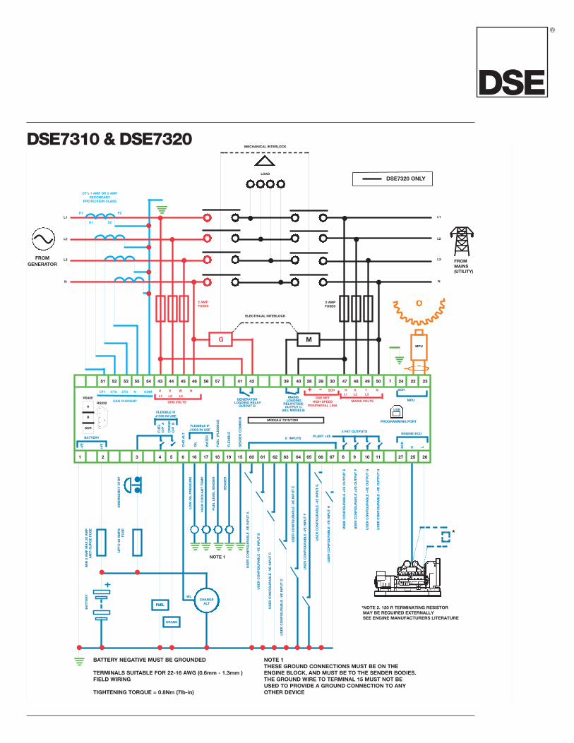
DSE7310 &DSE7320AUTOSTART & AUTOMAINS (UTILITY) FAILURECONTROLMODULES (COMMUNICATIONS & EXPANSION)
SPECIFICATION
DCSUPPLY
ALTERNATOR INPUT
MAINS/UTILITY INPUT (DSE7320 ONLY)
CONTINUOUS VOLTAGERATING8V to 35V Continuous
CRANKING DIP PROTECTIONAble to survive 0V for 50mS, providing supplywas at least 10V before dropout and supplyrecovers to 5V. This is achieved without the needfor internal batteries
CHARGE FAIL/ EXCITATION0V to 35V fixed power source 2.5W
MAXIMUM STANDBY CURRENT160mA at 12V 80mA at 24V
MAXIMUM OPERATING CURRENT340mA at 12V 160mA at 24V
RANGE15V - 333V (L-N) 50Hz - 60Hz(Minimum 15V AC Ph-N)
ACCURACY1% of full scale true RMS sensing
SUPPORTED TOPOLOGIES3 phase 4 wire3 phase 3 wireSingle phase 2 wire2 phase 3 wire L1 & L22 phase 3 wire L1 & L3
RANGE15V - 333V (L-N) 50Hz - 60Hz(Minimum 15V AC Ph-N)
ACCURACY1% of full scale true RMS sensing
SUPPORTED TOPOLOGIES3 phase 4 wire3 phase 3 wireSingle phase 2 wire2 phase 3 wire L1 & L22 phase 3 wire L1 & L3
CT’S
BURDEN0.5VA
PRIMARY RATING1A - 8000A (user selectable)
SECONDARY RATING1A or 5A secondary (user selectable)
ACCURACYOFMEASUREMENT1% of full load rating
RECOMMENDATIONSClass 1 required for instrumentationProtection class required if using for protection
Continued on page 2
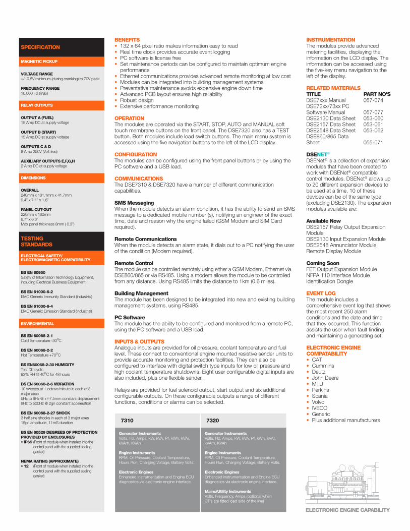
BENEFITS• 132 x 64 pixel ratio makes information easy to read• Real time clock provides accurate event logging• PC software is license free• Set maintenance periods can be configured to maintain optimum engineperformance
• Ethernet communications provides advanced remote monitoring at low cost• Modules can be integrated into building management systems• Preventative maintenance avoids expensive engine down time• Advanced PCB layout ensures high reliability• Robust design• Extensive performance monitoring
OPERATIONThe modules are operated via the START, STOP, AUTO and MANUAL softtouch membrane buttons on the front panel. The DSE7320 also has a TESTbutton. Both modules include load switch buttons. The main menu system isaccessed using the five navigation buttons to the left of the LCD display.
CONFIGURATIONThe modules can be configured using the front panel buttons or by using thePC software and a USB lead.
COMMUNICATIONSThe DSE7310 & DSE7320 have a number of different communicationcapabilities.
SMSMessagingWhen the module detects an alarm condition, it has the ability to send an SMSmessage to a dedicated mobile number (s), notifying an engineer of the exacttime, date and reason why the engine failed (GSM Modem and SIM Cardrequired).
Remote CommunicationsWhen the module detects an alarm state, it dials out to a PC notifying the userof the condition (Modem required).
Remote ControlThe module can be controlled remotely using either a GSM Modem, Ethernet viaDSE860/865 or via RS485. Using a modem allows the module to be controlledfrom any distance. Using RS485 limits the distance to 1km (0.6 miles).
BuildingManagementThe module has been designed to be integrated into new and existing buildingmanagement systems, using RS485.
PC SoftwareThe module has the ability to be configured and monitored from a remote PC,using the PC software and a USB lead.
INPUTS &OUTPUTSAnalogue inputs are provided for oil pressure, coolant temperature and fuellevel. These connect to conventional engine mounted resistive sender units toprovide accurate monitoring and protection facilities. They can also beconfigured to interface with digital switch type inputs for low oil pressure andhigh coolant temperature shutdowns. Eight user configurable digital inputs arealso included, plus one flexible sender.
Relays are provided for fuel solenoid output, start output and six additionalconfigurable outputs. On these configurable outputs a range of differentfunctions, conditions or alarms can be selected.
INSTRUMENTATIONThe modules provide advancedmetering facilities, displaying theinformation on the LCD display. Theinformation can be accessed usingthe five-key menu navigation to theleft of the display.
RELATEDMATERIALSTITLE PART NO’SDSE7xxx Manual 057-074DSE72xx/73xx PCSoftware Manual 057-077DSE2130 Data Sheet 053-060DSE2157 Data Sheet 053-061DSE2548 Data Sheet 053-062DSE860/865 DataSheet 055-071
DSENET®
DSENet® is a collection of expansionmodules that have been created towork with DSENet® compatiblecontrol modules. DSENet® allows upto 20 different expansion devices tobe used at a time. 10 of thesedevices can be of the same type(excluding DSE2130). The expansionmodules available are:
Available NowDSE2157 Relay Output ExpansionModuleDSE2130 Input Expansion ModuleDSE2548 Annunciator ModuleRemote Display Module
Coming SoonFET Output Expansion ModuleNFPA 110 Interface ModuleIdentification Dongle
EVENT LOGThe module includes acomprehensive event log that showsthe most recent 250 alarmconditions and the date and timethat they occurred. This functionassists the user when fault findingand maintaining a generating set.
ELECTRONIC ENGINECOMPATABILITY• CAT• Cummins• Deutz• John Deere• MTU• Perkins• Scania• Volvo• IVECO• Generic• Plus additional manufacturers7310 7320
Generator InstrumentsVolts, Hz, Amps, kW, kVA, Pf, kWh, kVAr,kVArh, KVAh
Engine InstrumentsRPM, Oil Pressure, Coolant Temperature,Hours Run, Charging Voltage, Battery Volts.
Electronic EnginesEnhanced Instrumentation and Engine ECUdiagnostics via electronic engine interface.
Generator InstrumentsVolts, Hz, Amps, kW, kVA, Pf, kWh, kVAr,kVArh, KVAh
Engine InstrumentsRPM, Oil Pressure, Coolant Temperature,Hours Run, Charging Voltage, Battery Volts.
Electronic EnginesEnhanced instrumentation and Engine ECUdiagnostics via electronic engine interface.
Mains/Utility InstrumentsVolts, Frequency, Amps (optional whenCT’s are fitted load side of the line)
TESTINGSTANDARDS
SPECIFICATION
MAGNETIC PICKUP
RELAYOUTPUTS
DIMENSIONS
ELECTRICAL SAFETY/ELECTROMAGNETIC COMPATIBILITY
ENVIRONMENTAL
VOLTAGERANGE+/- 0.5V minimum (during cranking) to 70V peak
FREQUENCY RANGE10,000 Hz (max)
OUTPUT A (FUEL)15 Amp DC at supply voltage
OUTPUT B (START)15 Amp DC at supply voltage
OUTPUTSC&D8 Amp 250V (Volt free)
AUXILIARYOUTPUTS E,F,G,H2 Amp DC at supply voltage
OVERALL240mm x 181.1mm x 41.7mm9.4” x 7.1” x 1.6”
PANEL CUT-OUT220mm x 160mm8.7” x 6.3”Max panel thickness 8mm ( 0.3”)
BS EN 60950Safety of Information Technology Equipment,including Electrical Business Equipment
BS EN 61000-6-2EMC Generic Immunity Standard (Industrial)
BS EN 61000-6-4EMC Generic Emission Standard (Industrial)
BS EN 60068-2-1Cold Temperature -30oC
BS EN 60068-2-2Hot Temperature +70oC
BS EN60068-2-30 HUMIDITYTest Db cyclic93% RH @ 40oC for 48 hours
BS EN 60068-2-6 VIBRATION10 sweeps at 1 octave/minute in each of 3major axes5Hz to 8Hz @ +/-7.5mm constant displacement8Hz to 500Hz @ 2gn constant acceleration
BS EN 60068-2-27 SHOCK3 half sine shocks in each of 3 major axes15gn amplitude, 11mS duration
BS EN 60529 DEGREESOF PROTECTIONPROVIDED BY ENCLOSURES• IP65 (Front ofmodulewhen installed into the
control panel with the supplied sealinggasket)
NEMARATING (APPROXIMATE)• 12 (Front ofmodulewhen installed into the
control panel with the supplied sealinggasket)
ELECTRONICENGINECAPABILITY
®
BATTERY
-VE
+VE CHGALT
OIL
WATER
FUEL
(FLE
XIBLE
)
SENDERCOMMON
FLEXIBLE
8 INPUTSPLANT +VE
GENERATORLOADING RELAY
OUTPUT D
MAINSLOADING
RELAY(7320)OUTPUT C
(ALL MODELS)FLEXIBLE IFJ1939 IN USE
FLEXIBLE IFJ1939 IN USE 4 FET OUTPUTS
ENGINE ECU
MPUSCR
SCR
H L
BATTERY NEGATIVE MUST BE GROUNDED
TERMINALS SUITABLE FOR 22-16 AWG (0.6mm - 1.3mm )FIELD WIRING
TIGHTENING TORQUE = 0.8Nm (7lb-in)
NOTE 1THESE GROUND CONNECTIONS MUST BE ON THEENGINE BLOCK, AND MUST BE TO THE SENDER BODIES.THE GROUND WIRE TO TERMINAL 15 MUST NOT BEUSED TO PROVIDE A GROUND CONNECTION TO ANYOTHER DEVICE
*NOTE 2. 120 R TERMINATING RESISTORMAY BE REQUIRED EXTERNALLYSEE ENGINE MANUFACTURERS LITERATURE
*
NOTE 1
CT1 CT2 CT3 N COM
51 52 53 55 54 43 44 45 46 56 57 41 42 39 40 28 29 30 47 48 49 50 7 24 22 23
1 2 3 4 5 6 16 17 18 19 15 60 61 62 63 64 65 66 67 8 9 10 11 27 25 26
U V W N
L1 L2 L3
R S T NL1 L2 L3
GEN VOLTS MAINS VOLTS
+ - SCR
DSE NETHIGH SPEED
PERIPHERAL LINKGEN CURRENT
EMERGENCYSTOP
LOW
OIL
PRESSURE
HIGHCOOLA
NTTEMP
FUELLE
VELSENDER
SENDER
USERCONFIGURABLE
-VEINPUTA
USERCONFIGURABLE
-VEINPUTB
USERCONFIGURABLE
-VEINPUTC
USERCONFIGURABLE
-VEINPUTD
USERCONFIGURABLE
-VEINPUTE
USERCONFIGURABLE
-VEINPUTF
USERCONFIGURABLE
-VEINPUTG
USERCONFIGURABLE
-VEINPUTH
USERCONFIGURABLE
+VEOUTPUTE
USERCONFIGURABLE
+VEOUTPUTF
USERCONFIGURABLE
+VEOUTPUTG
USERCONFIGURABLE
+VEOUTPUTH
UPTO32
AMPS
FUSE
MIN
2AMPMAX20
AMP
ANIT-SURGEFU
SE
BATTERY
FUELFUEL
WL
CRANK
CHARGEALT
2 AMPFUSES
CT’s 1 AMP OR 5 AMPSECONDARY
PROTECTION CLASS
P1 P2
S1 S2
MPU
M
2 AMPFUSES
ELECTRICAL INTERLOCK
MECHANICAL INTERLOCK
LOAD
L3
N
L2
L1
L3
N
L2
L1
FROMMAINS(UTILITY)
FROMGENERATOR
FUEL
O/P
A
CRANK
O/P
B
RS485
RS232
SCR
B
A
PROGRAMMING PORT
USB
G
DSE7320 ONLY
MODULE 7310/7320
DSE7310 &DSE7320
055-051/02/09 (4)USA
®
YOUR LOCAL DISTRIBUTOR.
DEEP SEA ELECTRONICS PLCmaintains a policy of continuous development and reserves the right tochange the details shown on this data sheet without prior notice. The contents are intended for guidance only.
This data sheet is printed on 9lives 55 Silk, which is produced with 55% recycled fibrefrom both pre and post-consumer sources, together with 45% virgin ECF fibre.
DEEP SEA ELECTRONICS INC3230 Williams AvenueRockfordIL 61101-2668 USA
TELEPHONE+1 (815) 316 8706
FACSIMILE+1 (815) 316 8708
WEBSITEwww.deepseausa.com
DEEP SEA ELECTRONICS PLCHighfield HouseHunmanby Industrial EstateHunmanby, North YorkshireYO14 0PH England
TELEPHONE+44 (0)1723 890099
FACSIMILE+44 (0)1723 893303
WEBSITEwww.deepseaplc.com
Registered in England & Wales No.01319649 VAT No.316923457
PENDING