model taf - cincinnati fan
TRANSCRIPT

OMM-15-0509-page 1
Installation, Safety, Operation & Maintenance Instructions And Parts ListFor Models TAF,WAF, HTF &WAF/HTF, Belt Drive Tube Axial Fans
Arrangement 9
All Cincinnati Fan products are packaged to minimize any damage during shipment. The freight carrier is responsiblefor delivering all items in their original condition as received from Cincinnati Fan. The individual receiving this equipmentis responsible for inspecting this unit for any obvious or concealed damage. If any damage is found, it should be notedon the bill of lading before the freight is accepted and the receiver must file a claim with the freight carrier.
ATTENTION: RECEIVING DEPARTMENT
LONG TERM STORAGE NOTICE
If this fan will NOT be installed and put into operation within 30 days, refer to the “Long Term StorageInstructions” on page 15. Failure to follow all applicable long term storage instructions, will void your warranty.This fan should be stored indoors in a clean, dry location.
FAN SERIAL NUMBER: ________________________ MFG. DATE: ____________________
NOTE: The serial number above is a required reference for any assistance. It is stamped on the fan nameplate.
FAN SPECIFICATIONS:
Model: ________ Propeller Number: ___________________
FAN PERFORMANCE DATA: (If entered on order)
CFM: ________ SP: ________ (Inches of Water Gauge) Motor BHP: ________
Density: ________ Altitude: ________ (Ft. above S.L.) Airstream Temperature: ________°F.
Fan RPM: ________ Maximum Safe Fan RPM: ____________ DO NOT EXCEED THIS RPM
MOTOR DATA: (This section is completed only if the motor was supplied by Cincinnati Fan)
HP: __________ RPM: ____________ Voltage: ______________________________ Phase:________
Hz: ___________ Frame Size: ___________ Enclosure: ____________ Efficiency: ____________
IF Motor is EXP, Class(es) & Group(s) are:_________________________
Manufacturers Model Number: ___________________________ CFV Part Number: ___________
DRIVE DATA:
Fan Sheave: ______________ Motor Sheave: _______________ Belts: ______________
No. of Grooves: ___________ Fixed Speed: �� Adjustable Speed: ��
FAN SPECIFICATIONS
Form: OMM-15-0509Effective: 5/4/09Supersedes: OMM-15-0507Part No.: 01236
READ ENTIRE MANUAL, INCLUDING “SECTION IV. INITIAL UNIT STARTUP” BEFORE ATTEMPTING TO INSTALL AND OPERATE THIS EQUIPMENT.
NOTE

DANGER
OMM-15-0509-page 2
TABLE OF CONTENTS
Hazardous voltage High speed rotating Lock out/Tag out to Avoid injury. NEVER Avoid injury. You MUSTcan cause electrical equipment can cause prevent personal injury operate without ALL read and understand allshock and death. severe personal injury. BEFORE starting ANY required safety instructions in this manual
service or inspection. guards in place. BEFORE installing.
I. GENERAL
A. Unpacking:
Be careful not to damage or deform any parts of the fan when removing it from the packaging container. All thepackaging material should be kept in the event the fan needs to be returned.
Handling:Handling of the fan should be performed by trained personnel and be consistent with all safe handling practices.Verify that all lifting equipment is in good operating condition and has the proper lifting capacity. The fan should belifted using well-padded chains, cables or lifting straps with spreader bars. NEVER lift the fan by an inlet ordischarge flange, fan or motor shaft, motor eye bolt, or any other part of the fan assembly that could causedistortion of the fan assembly.
B. Safety Instructions & Accessories:
1. Safety Instructions:All installers, operators and maintenance personnel should read AMCA Publication 410-96, “Recommended SafetyPractices for Users and Installers of Industrial and Commercial Fans”. This manual is included with the fan.Additional copies can be requested by writing us at Cincinnati Fan, 7697 Snider Rd., Mason, OH 45040-9135
2. Sound:Some fans can generate sound that could be hazardous to personnel. It is the responsibility of the user to measure thesound levels of the fan and/or system, determine the degree of personnel exposure, and comply with all applicablesafety laws and requirements to protect personnel from excessive noise.
I. GENERAL A. Unpacking and Handling ..................................2B. Safety Instructions & Accessories .................2-3
II. INSTALLATIONA. Vibration............................................................3B. Mounting Methods ............................................4C. Safety Guards...................................................4D. Dampers and Shutters......................................4E. Set Screw and Taper-lock BushingTorque Values....................................................4
F. Fan Bearings ....................................................5G. V-Belt Drives .....................................................5H. V-Belt Drive Installation .................................5-6
III. ELECTRICALA. Disconnect Switches.........................................6B. Motors............................................................6-7C. Maximum Speed & Speed Controllers .............8
IV. INITIAL UNIT STARTUPA. Pre-Startup & Post-Startup Checks..................8B. Vibration............................................................9
V. ROUTINE INSPECTION & MAINTENANCEA. Hardware ..........................................................9B. Motor or Fan Bearing Lubrication................9-10C. Propeller Balance ...........................................10D. Vibration..........................................................11E. Fan Shaft or Bearing Replacement ...........11-12F. Dampers and Shutters....................................12G. Safety Equipment or Accessories...................13
VI. ORDERING REPLACEMENT PARTS ..................13
VII. TROUBLESHOOTING ...........................................14
VIII. LONG TERM STORAGE .......................................15
IX. WARRANTY, LIMITS OF LIABILITY,RESPONSIBILITY & RETURNS..........................16
X. PARTS DRAWING.................................................17

OMM-15-0509-page 3
3. Air Pressure and Suction:In addition to the normal dangers of rotating machinery, the fan can present additional hazards from the suction or pressurecreated at the fan inlet or discharge. Suction at the fan inlet can draw materials into the fan where they become high veloci-ty projectiles at the discharge and cause severe personal injury or death. It can also be extremely dangerous to persons inclose proximity to the inlet or discharge as the forces involved can overcome the strength of most individuals.
NEVER OPERATE A FAN WITH A NON-DUCTED INLET AND/OR DISCHARGE. IF THE FAN INLET AND/OR DISCHARGE IS NON-DUCTED, IT IS THE USERS RESPONSIBILITY TO INSTALL AN
INLET AND/OR DISCHARGE GUARD.
NO GUARANTEE OF ANY LEVEL OF SPARK RESISTANCE IS IMPLIED BY SPARK RESISTANT CONSTRUCTION.IT HAS BEEN DEMONSTRATED THAT ALUMINUM IMPELLERS RUBBING ON RUSTY STEEL CAN CAUSE HIGH
INTENSITY SPARKS. AIR STREAM MATERIAL AND DEBRIS OR OTHER SYSTEM FACTORS CAN ALSO CAUSE SPARKS.
4. Temperature:Many fans, fan components and all motors operate at temperatures that could burn someone if they come in contact withthem. If this potential hazard could exist in your installation, steps must be taken by the user to protect anyone from comingin contact with this equipment. The maximum airstream temperature for this fan is:
6. Safety Accessories:Guards:All moving parts must be guarded to protect personnel. Safety requirements can vary, so the number and types of guardsrequired to meet company, local, state and OSHA regulations must be determined and specified by the actual user or oper-ator of the equipment.
NEVER start any fan without having all required safety guards properly installed. All fans should be checked on aregular schedule, for missing or damaged guards. If any required guards are found to be missing or defective, thepower to the fan should be immediately turned off and locked out in accordance with OSHA regulations. Power tothe fan should NOT be turned back on until the required guards have been repaired or replaced.
This fan can become dangerous due to a potential “windmill” effect, even though all electrical power has been turned off ordisconnected. The fan propeller should be carefully secured to prevent any rotational turning BEFORE working on anyparts of the fan/motor assembly that could move.
7. Access or Inspection Doors:
II. INSTALLATION
A. Vibration:
Before any mounting method is selected, the user should be aware of the effects vibration will have on the fan, motor andother parts. Improper fan installation can cause excessive vibration causing premature prop and/or bearing failure, that isnot covered under warranty. Vibration eliminator pads or springs should be properly installed to prevent any fan vibrationfrom transmitting to the foundation or support structure.
WARNING
DANGER
I
SHUT THE FAN DOWN IMMEDIATELY IF THERE IS ANY SUDDEN INCREASE IN VIBRATION.
WARNING
NEVER OPEN ANY ACCESS OR INSPECTION DOORS WHILE THE FAN IS OPERATING. SERIOUS INJURY OR DEATHCOULD RESULT FROM THE EFFECTS OF AIR PRESSURE OR AIR SUCTION. DISCONNECT OR LOCK OUT POWERTO THE FAN AND LET THE FAN PROPELLER COME TO A COMPLETE STOP BEFORE OPENING ANY TYPE OF
ACCESS OR INSPECTION DOOR.
DANGER
5. Spark Resistance: (Per AMCA Standard 99-0401-86 and ISO 13499)
Fan Models
Max. AirstreamTemperature
TAF & WAF
HTF & WAF/HTF
200°F (93°C)
375°F (191°C)

B. Mounting Methods:1. In Duct Work
Any component of a building structure that will be supporting the fan and any duct work must have the weight loadcapacity and be rigid enough to support the weight of the fan without bending, bowing or flexing during operation. Ifnot, severe vibration can occur that could lead to fan and/or structural failure. Consult an architectural or structuralengineer for assistance.
Tube axial fans are designed to be mounted in duct work of the same diameter as the fan. The flange rings are pre-punched and should be bolted to duct flanges having the same dimensions. We do offer companion rings, as anoption, to make the connection process easier. These fans can be mounted with the fan and motor shaft in a hori-zontal or vertical up-blast (motor shaft down) configuration.
OMM-15-0509-page 4
If this fan will be mounted in a vertical down-blast configuration, with the motor shaft up, the pro-peller MUST be secured to the fan shaft with a pin or locking collar. If there is no pin or locking collarto additionally secure the propeller to the fan shaft, DO NOT use the fan without adding this feature.Not providing this feature could lead to property damage, injury or death.
DANGER
Set screws should NEVER be used more than once. If the set screws are loosened, they MUST be replaced.Use only knurled, cup-point, set screws with a nylon locking patch.
CAUTION
SET SCREW TORQUE VALUES TORQUE VALUES FORTAPER-LOCK BUSHINGSDiameter & Number
of Treads/InchHex Wrence Size
(Across Flats)Required Torque
(Inch Pounds)
1/4-205/16-183/8-167/16-141/2-135/8-11
1/8”5/32”3/16”7/32”1/4”5/16”
65165228348504
1104
Taper-lockBushing Size
Required Torque(Inch Pounds)
H
BPQR
95
192192350350
Table 2Table 1
The use of flexible connectors on the inlet and outlet of the fan will make it possible to mount this fan in a duct systemand isolate any fan/motor vibration from the duct work. If flexible connectors will be used, the fan should be equippedwith horizontal or vertical support clips. Threaded rod should be used to connect the support clips to the building struc-ture. Each rod should be strong enough to support two (2) times the weight of the entire fan/motor assembly. Springhangers would be needed on the rods to isolate any fan vibration from the building.
2. On MachineryIf this fan will be mounted on machinery, the surface it will be mounted to must be strong and rigid enough to supportthe weight of the entire fan without flexing, bowing, bending or oil-canning and thus causing vibration. Companion ringsare available that will match the flanges on this fan. To minimize any leakage, it is recommended that some type ofcaulking be used between the fan flange and the machine.
C. Safety Guards:Cincinnati Fan offers guards, as optional, to keep your fan in compliance with OSHA safety regulations. These includeinlet or discharge guards and belt guards. It is the responsibility of the user to make sure this fan meets all local, stateand OSHA safety regulations. If you have a specific guard requirement not covered by OSHA, please contact the localCincinnati Fan sales office for assistance.
D. Dampers and Shutters: (Airflow control devices)If the fan is supplied with any type of air flow control device, it should be closed before initial startup of the fan to mini-mize overloading of the motor. Any airflow control device, with bearings, should be maintained in accordance with themanufacturers instructions. Any air flow control device, with an automatic control mechanism, should be adjusted perthe manufacturers recommendations.
E. Set Screw and Taper-lock Bushing Torque Values:All propeller set screws are tightened to the proper torque prior to shipment. Some props may have taper-lock hubsand split, taper-lock bushings to secure the prop to the fan shaft.NOTE: Check all set screw or taper-lock bushing torques. Forces encountered during shipment, handling, rigging andtemperature can affect factory settings. For correct torque values, see Tables 1 and 2 below.

OMM-15-0509-page 5
F. Fan Bearings:If the fan bearings have set screws to lock the bearings onto the fan shaft, the set screws should be tightened to thesame torque levels as shown in Table 1 on page 4. Fan bearings should be lubricated in accordance with the bearingmanufacturer’s recommendation and with the same type of grease. See chart under Section B-2 on page 11. Thefan bearings are pre-lubricated at the factory. The fan bearing cover should only be removed during inspectionor maintenance, but only after the power to the motor has been turned off and locked out. The bearing coverMUST be replaced before the power is turned back on.
G.V-Belt Drives:If Cincinnati Fan supplied the belts and sheaves (drives package), they were carefully selected for the specific operat-ing conditions supplied to us by the customer.
If the user is supplying the sheaves and/or belts, it is their responsibility to make the correct component selections forthe specific operating conditions. Their selection must also NOT ALLOW the fan to exceed its maximum safe speedor hub load. If you do not know the maximum safe speed or hub load for this fan, DO NOT make any drive selectionwithout first consulting Cincinnati Fan or our sales office for your area. “Timing” belts should never be used onfans. If you are replacing belts and/or sheaves, checking belt tension or proper alignment, see below and page 6.Sheave set screws or taper-lock bushing bolts should be tightened to the torque values as indicated in Tables 1 and/or2 on page 4.
H. V-Belt Drive Installation:Power to the motor must be turned off and locked out, BEFORE inspecting, installing or servicing any compo-nents of the drives. READ AND FOLLOW ALL THE STEPS BELOW AND ON PAGE 6.
If you are installing any new belts, inspect and replace any worn or damaged sheaves, bearings or shafts while thepower is turned off and locked out. This will eliminate additional down time later to replace any other parts that wereworn or defective.
Changing any of the v-belt drive component selections, supplied with the fan, could result in unsafeoperating conditions which could cause equipment failure, personal injury and death.
DANGER
Fig. 1
Shafts not parallel Sheaves not aligned Proper alignment
ASSEMBLY STEPS: (Below are general instructions. Obtain specific instructions from your drives dealer)NOTE: The fan must be removed from the duct work or machine to install or replace the drives
1. Lockout and disconnect power to the motor.2. Remove belt guard or belt guard/weather cover, if supplied.3. Remove the screws that hold the bearing cover to the bearing base. Remove the cover.4. The adjustable motor base should be used for belt tension adjustment. Loosen the tension on the belts by first loos-
ening the 4 “locking bolts” in the side of the base, but DO NOT remove these bolts.5. Turn the 4 “tensioning bolts” in the top of the motor base counter-clockwise, so the motor base moves as close to
the fan drum as possible. This will reduce the tension on the belts.6. Remove belt(s) from the motor sheave and then the fan sheave. Remove belt(s) from through the belt tube.
If replacing belts and sheaves, go on to Step 7. If replacing belts only, go to Step 12 on page 6.7. Loosen set screws or taper-lock bolts in the fan sheave and the motor sheave. Remove sheaves.8. Check the fan and motor shafts for any nicks or burrs. Remove any burrs with a file or emery paper.9. Slide new sheaves onto the fan and motor shafts. DO NOT drive or pound the sheaves on as this may damage the
fan and/or motor bearings.10. Align the fan and motor sheaves with a straight-edge (or string) as shown in Fig. 2 on page 6. If the sheaves are not
the same width, align by sight. For more precise methods, consult your local drives dealer.NOTE: Any sheave with a taper-lock bushing will slide a little on the shaft as the bolts are tightened. You will need to
compensate for the sliding before performing Step 12 on page 6.If you are also replacing the motor, you might need to adjust the motor on the motor base to keep the fanand motor shafts parallel as shown in Fig. 1 above.
If you are installing a complete set of new drives, the mostcritical steps of the installation are alignment of the sheavesand belt tension. Misaligned sheaves and/or improperbelt tension will cause excessive fan vibration andresult in premature belt and /or bearing failure.
The fan and motor shafts must be parallel and the sheavesmust be in line with each other. See Fig. 1 at right.
For complete drive installationinstructions, please see thesewebsites:
www.emerson-ept.com/catalogs/instshts/browning/form5453.pdfORwww.maskapulleys.com/images/produit/Product%20Training_jan09.1.pdf

OMM-15-0509-page 6
Straight edgeshould touchsheaves atthese 4 points.
Straight Edge Too Tight
Too LooseProper Tension(Slight Bow)
Fig. 2 Fig. 3
11. Slide the belt(s) into the belt tube and place the belt(s) over the sheaves. DO NOT force, pry or “roll” the belts, as thiscould damage the cords in the belt(s). If there is more than 1 belt, all the belts should be a “matched set”.
12. After the sheaves are properly aligned and parallel, tighten the set screws and/or taper-lock hub bolts in the sheavesto the correct torque values shown in Tables 1 and/or 2 on page 4.
13. Adjust the motor base, by turning the 4 “tensioning bolts” in the top of the base clockwise, until the belts appear tobe snug, then recheck the alignment as in Step 10 on page 5.
14. Finger tighten the “locking bolts” in the side of the base.WARNING: BEFORE ATTEMPTING THE FOLLOWING STEPS, MAKE SURE THE AREA AROUND THE FAN IS
SAFE AND SECURED SO NO ONE CAN GET NEAR THE FAN AND GET INJURED WHEN IT ISSTARTED. USE CAUTION AND GOOD JUDGMENT.
15. Reconnect or unlock power to the motor and run the fan for a few minutes to allow belts to “seat” properly. Then turnoff and lock out the power to the motor.
16. Loosen the 4 “locking bolts”, in the side of the motor base, and re-adjust the belt tension using the 4 “tensioningbolts” in the top of the base.
17. Tighten the 4 “locking bolts” in the side of the motor base.18. Unlock power to motor and run the fan. The belts should be running as shown in Fig. 3 below. If not, repeat Steps
10-14 above after you have turned off power to the motor.19. Disconnect power to the motor.20. Reinstall the bearing cover and any safety guards.21. Reinstall fan into the duct system or machine.22. Reconnect power to the motor and turn on.23. After running the fan for 3 days, lock out and disconnect power to the motor and remove fan from the duct sys-
tem or machine.24. Connect power to the motor and repeat Step 18 above.25. Repeat any other steps as necessary.
ALL WIRING CONNECTIONS, INSPECTION AND MAINTENANCE OF ANY MOTOR MUST BE PERFORMED BY ALICENSED ELECTRICIAN IN ACCORDANCE WITH THE MOTOR MANUFACTURERS RECOMMENDATIONS, ALL
ELECTRICAL CODES AND OSHA REGULATIONS. FAILURE TO PROPERLY INSTALL, MAKE WIRINGCONNECTIONS, INSPECT OR PERFORM ANY MAINTENANCE TO A MOTOR CAN RESULT IN MOTOR FAILURE, PROPERTY DAMAGE, EXPLOSION, ELECTRICAL SHOCK AND DEATH.
DANGER
III. ELECTRICAL
A. Disconnect Switches:All fan motors should have an independent disconnect switch located in close visual proximity to turn off the electri-cal service to the fan motor. Disconnects must be locked out in accordance with OSHA “lock out-tag out” pro-cedures before any inspection or maintenance is performed on the fan and/or motor assembly. The “lockout-tag out” procedure should be performed by a licensed electrician or authorized personnel.All disconnects should be sized in accordance with the latest NEC codes (National Electric Codes) and any localcodes and should be installed only by a licensed electrician. “Slow blow” or “time delay” fuses or breakers should beused since the initial start-up time for the fan motor, although rare, can be up to 10 seconds.
B. Motors:
1. DO NOT connect or operate a motor without reading the motor manufacturers instructions supplied withthe fan. The basic principle of motor maintenance is: KEEP THE MOTOR CLEAN AND DRY. This requires peri-odic inspections of the motor. The frequency of the inspections depends on the type of motor, the service andenvironment it will be subjected to and the motor manufacturers instructions.

OMM-15-0509-page 7
2. Cleaning: Cleaning should be limited to exterior surfaces only. Follow motor manufacturers cleaning instruc-tions.
3. Lubrication: Most small motors have sealed bearings that are permanently lubricated for the life of the motor.Some larger motors have grease plugs that should be replaced with grease fittings to perform re-lubrication.These motors, or any motor with grease fittings, should be lubricated in accordance with the motor manufacturersrecommendations. Lubrication frequency depends on the motor horsepower, speed and service. BE SURE youuse compatible grease and DO NOT over grease.
4. Location: A standard Open Drip Proof or Totally Enclosed type motor is suitable in a clean, dry location below104°F. (40°C). If the location will be wet, dirty or reach temperatures above 104°F (40°C), a different type of motormay be necessary. Consult our local sales office for your area for proper motor selection assistance. All wiringmust meet NEC (National Electric Codes) standards.
5. Wiring Connections: All wiring connections should be made for the proper voltage and phase as shown on themotor nameplate. Connections should follow the motor manufacturers recommendations as shown on the wiringschematic. This wiring diagram will be located on the outside of the motor, inside of the motor conduit box or onthe motor nameplate. Reversing some wires might be necessary to get the correct fan rotation.
6. Motors with Thermal Overload Protection: If a motor is equipped with thermal overloads, the thermal overloadmust be wired per the wiring schematic to be operable. There are 3 types of thermal overloads:
a. Automatic: These will automatically shut the motor down if the internal temperature exceeds the design limits.
b. Manual: These motors will have a button on them. If the motor overheats, it will shut down. After you haveinspected the motor and eliminated the over heating problem, you will need to “reset” it by pushing the button.You should still lock out the power BEFORE inspecting the motor.
c. Thermostats: This type of thermal is a temperature sensing device ONLY. If the motor overheats, the thermo-stats will open or close (depending on the type) and send a “signal” to the electrical box. THEY WILL NOTTURN THE MOTOR OFF. These are pilot circuit devices that must be connected to the magnetic startercircuit.
7. EXPLOSION PROOF Motors: No motor is explosion proof. Explosion proof (EXP) motors are designed so if there isan explosion WITHIN the motor, the explosion will be CONTAINED INSIDE the motor and not allowed to get out tothe atmosphere. All explosion proof motors must be selected based on the atmosphere and/or the environment themotor will be operating in. Explosion proof motors are designed, rated, and labeled for their operating conditionsbased on Classes, Groups and “T” Codes. The Class, Group and “T” Code of an EXP motor MUST be selectedbased on the atmosphere and/or environmental conditions the motor will be operating in. Consult the NEC(National Electric Code) and the NFPA (National Fire Protection Association) for the proper EXP motorClass, Group and “T” Code required for your specific application and location.
IF AN EXPLOSION PROOF MOTOR IS USED IN AN AREA CONTAINING VOLATILE LIQUIDS, GASES, FUMES OR DUST FOR WHICH THE MOTOR WAS NOT DESIGNED TO OPERATE IN, AN
EXPLOSION AND/OR FIRE CAN OCCUR.
DANGER
MAKE SURE YOU LOCK OUT THE POWER TO THE MOTOR BEFORE INSPECTING ANY MOTOR WITHAUTOMATIC THERMALS. WHEN THE THERMALS COOL DOWN, THEY WILL ALLOW THE MOTOR TOAUTOMATICALLY START UP AGAIN, UNLESS YOU HAVE LOCKED OUT THE POWER TO THE MOTOR.
DANGER
NOTICE:a. All EXP motors have some type of thermal overload as required by UL (Underwriters Laboratories). Refer to all of Section 6 above.
b. All EXP motors are required to have the UL (Underwriters Laboratories) and CSA (Canadian Standards Association) listing numbers on the motor name plate or on a separate plate attached to the motor. The Class, Group and “T” Code the motor is designed for must also be listed.
8. Normal Motor Operating Temperatures:Using your hand to test the normal running temperature of a motor can be a very painful experience;The normal operating temperature of a fully loaded, open type, electric motor operating in a 70°F. (21° C.)ambient temperature is 174°F. (79° C.)

OMM-15-0509-page 8
C. Maximum Fan Speed and Motor Speed Controllers:If you will be using any type of motor speed controller with this fan, DO NOT exceed the maximum safe fan speed.Installing and using a speed control device requires special training and certification as required by the speed con-trol manufacturer. See the manufacturers instructions for proper use, installation and wiring connections for the maxi-mum speed settings. It may also be necessary to “block out” some speeds to eliminate a resonant vibration problem.The maximum safe fan speed is shown on the data sheet shipped with the fan. If you have lost the data sheet, con-tact Cincinnati Fan or our sales office for your area. You must have the serial number from the fan name plate for usto determine the maximum safe fan speed. Cincinnati Fan will only extend the motor manufacturers warranty, whenused with a speed controlling device, if the motor has the words “Inverter Duty” marked on the motor name plate. Ifthe motor does not have “Inverter Duty” marked on the motor name plate, and you have a motor failure, you will berequired to contact the motor manufacturer for any service or warranty claims.
IV. INITIAL UNIT STARTUP
A. Pre-Startup & Post-Startup Checks: (Check blocks as each step is completed. Retain this for your records.)A1. Pre-Startup Checks Completed By: ___________________________________ DATE: ___________________
A2. 8 Hour, Post-Startup Checks Completed By: _______________________ DATE: ___________________A3. 3 Day, Post-Startup Checks Completed By: _____________________ DATE: ___________________
MAKE SURE POWER TO THE MOTOR IS LOCKED OUT BEFORE STARTING PRE-STARTUP OR POST-STARTUP CHECKS.
BEFORE MOUNTING FAN IN DUCT WORK OR ON A MACHINE:If you will be mounting this fan into a duct system, and there is no access door in the fan drum, it is strongly recom-mended that an access door be installed in the duct work section next to the fan. That will allow you access to performthe post-startup checks more easily.
1. Check the propeller by spinning it by hand to ensure it rotates freely.2. Check the propeller set screws to make sure they are tight per Table 1 on page 4.3. If the propeller has a taper-lock bushing, make sure the bolts are tightened per Table 2 on page 4.4. Make certain there is no foreign material in the fan or duct work that can become a projectile.5. Ensure all electrical power components are properly sized and matched for your electrical system.6. Record the Full Load Amps listed on the motor nameplate. You will need to refer to this later.
Low Voltage: _________________________
High Voltage: ________________________
AFTER MOUNTING FAN IN DUCT WORK OR ON A MACHINE:
7. Check all duct work hardware to make sure it is tight.8. Make sure any inspection doors in the duct work are securely bolted or locked.9. Check that any required guards are properly secured.
10. Any dampers or valves should be fully opened and closed to make sure there is no binding or interference.11. If your fan is mounted on an elevated support structure, make sure the structure is welded at all the joint connections
and the structure is properly braced to prevent any “side sway”.12. Make sure the propeller is stationary prior to startup. Starting a fan with a prop that is rotating backwards can
cause propeller damage.13. Make the necessary wiring connections to the motor per National Electric Code (NEC) regulations.14. Apply power to the fan motor momentarily (i.e. “bump start”) to check the propeller rotation. If the fan is rotating in the
wrong direction, reconnect the motor leads per the motor manufacturers wiring schematic. The fan rotation mustmatch the rotation indicated by the rotation arrow decals on the outside of the fan drum. After reconnecting theleads, repeat this step.
15. Apply power to the fan motor and let it come up to full speed. Turn off the power. Listen for any unusual noise ormechanical abnormality while the propeller is still spinning. If any are noticed, lock out the power, wait for the propellerto come to a complete stop, locate the cause and correct it.
16. Unlock power and start the fan.17. Measure, record and keep the following motor data for future reference and comparison.
(Single phase motors will only have L1 and L2 leads.)
Amperage draw on each motor lead: L1 _______ L2 _______ L3 _______(Running amps SHOULD NOT exceed the motor nameplate amps for the voltage being operated on). Comparethese amp readings to the Full Load Amps you recorded in Step 6 above.
Voltage coming to motor leads: L1_______ L2_______ L3_______ (Should be about the same input voltage on all leads).
NOTICE: Failure to complete and document all the following pre-startup and both post-startupchecks, listed in sections A (below) and B on page 9, could void all warranties.

OMM-15-0509-page 9
B. Vibration:All props are balanced to comply with ANSI S2.19, G6.3. However, rough handling in shipment and/or erection, weakand/or non-rigid foundations, and misalignment may cause a vibration problem after installation. After installation, thevibration levels should be checked by personnel experienced with vibration analysis and vibration analysis equipment.
BEFORE STARTING ANY INSPECTION OR MAINTENANCE, BE SURE FAN IS TURNED OFF, POWER IS LOCKEDOUT AND THE PROPELLER HAS BEEN CAREFULLY SECURED TO PREVENT WIND MILLING. IF THE
OPERATING CONDITIONS OF THE FAN ARE TO BE CHANGED (SPEED, PRESSURE, TEMPERATURE, ETC.)CONSULT CINCINNATI FAN, OR OUR SALES OFFICE FOR YOUR TERRITORY, TO DETERMINE IF THE UNIT WILL
OPERATE SAFELY AT THE NEW CONDITIONS.
WARNING
V. ROUTINE INSPECTION & MAINTENANCE
Periodic inspection of all the fan parts is the key to good maintenance and trouble-free operation. The frequency of inspec-tions must be determined by the user and is dependent upon the severity of the application. BUT, it should NEVER exceeda 12 month period. The user should prepare an inspection and maintenance schedule and make sure it is adhered to.
A. Hardware:
All fan hardware should be checked to make sure it is tight. All set screws or taper-lock bushing bolts should betightened to the torque values shown in Tables 1 and 2 on page 4.NOTE: If any set screws have become loose, they must be thrown away and replaced. NEVER use set screws more
than once. Replace with knurled, cup-point set screws with a nylon locking patch.
B. Motor and Fan Bearing Lubrication:
1. Motor Bearings:Most smaller motors have sealed bearings that never require re-lubrication for the life of the motor. For any motorswith grease fittings, consult the motor manufacturers recommendations with reference to the lubrication frequencyand the type of grease that should be used. DO NOT over grease the motor bearings. Generally, 1-2 shots should be enough. Use a hand operated grease gunat no more than 40 PSI. IF POSSIBLE, CAREFULLY lubricate the motor bearings while the motor is running.

OMM-15-0509-page 10
C. Propeller Balance:All propellers are balanced at the factory. It is not uncommon that additional “trim balancing” is required after thefan is assembled. Trim balancing of the fan assembly, in the field, is typically always necessary for all replacementprops.
Airstream material or chemicals can cause abrasion or corrosion of the fan parts. This wear is generally unevenand, over time, will lead to the prop becoming unbalanced causing excessive vibration. When that happens, theprop must be rebalanced or replaced. The other airstream components should also be inspected for wear or struc-tural damage and cleaned or replaced if necessary. After cleaning any prop, it should be balanced.
There are two ways to balance a propeller:
1. Add balancing weights for fabricated aluminum, steel or stainless steel props:Balance weights should be rigidly attached to the prop at a location that will not interfere with the fanhousing nor disrupt air flow. They should (if at all possible) be welded to the prop. When trim balancingthe propeller, on the fan shaft, be sure to ground the welder directly to the prop. Otherwise, the weldingcurrent will likely pass through the fan shaft and damage the fan and/or motor bearings.
2. Grinding off material for cast aluminum props:When grinding on the prop to remove material, be very careful not to grind too much in one area. Thatcould affect the structural integrity of the prop.
FAN OPERATING
SPEED (RPM)1/2” TO
1”11/8” TO
11/2”15/8” TO 115/16”
2” TO 21/2”
211/16” TO 33/16”
37/16” TO 315/16”
FAN SHAFT O.D. IN INCHES
6665554322
UP TO 500501-10001001-15001501-20002001-25002501-30003001-35003501-40004001-45004501-5000
6655543321
665432211—
6543221———
543221————
5421——————
The above lubrication frequencies are based on the fan bearings operating in a clean and dry environment from -20°F (-29°C) up to 120°F (49°C). For hostile, moisture laden environments
and/or temperatures below -20°F (-29°C) or above 120°F (49°C), consult the bearing manufacturer for the proper grease type and recommended lubrication frequencies.
If possible, carefully lubricate the bearings while the fan is running.
Add grease until a slight bead appears at the bearing seals. DO NOT over grease. Generally, 1-2 shots with a hand grease gun that has a maximum pressure rating of 40 PSI.
Warning: Over greasing bearings will cause them to run hot.
The TYPE of grease you use MUST BE compatible with the grease already in the bearings.
THIS FAN IS EQUIPPED WITH BEARINGS PRE-LUBRICATED AND READY FOR USEGenerally Recommended Lubrication Frequency in MONTHS
2. Fan Bearings:The fan bearings should be re-lubricated per the chart below and on the outside of the fan drum. Use this chartfor all clean and dry applications where the fan airstream temperature is -20°F (-29°C) up to 200°F (93°C). Thiswould be the correct temperature limits for Model TAF and WAF fans. Although the airstream temperature canbe up to 200°F (93°C), the fan bearings (inside the bearing cover) will only be subjected to a maximum of120°F (49°C).
For Models HTF and HTF/WAF fans, the maximum airstream temperature limit is 375°F (191°C). A chart simi-lar to the chart below will also specify that only Dow Corning DC-44 high temperature (silicone based)grease should be used.
DO NOT overgrease the fan bearings. Generally, 1-2 shots should be enough. Use a hand-operated greasegun at no more than 40 PSI. IF POSSIBLE, CAREFULLY LUBRICATE THE FAN BEARINGS WHILE THEFAN IS RUNNING.

OMM-15-0509-page 11
D. Vibration:
As mentioned previously in this manual, excessive vibration can cause premature motor and/or fan bearing failure thatcould lead to catastrophic failure of the fan. After performing any routine maintenance, the vibration readings should betaken again. New readings should be taken (maximum every 12 months) and compared to the readings you recordedpreviously. If any major differences are present, the cause should be determined and corrected before the fan isput back into operation.The most common causes of vibration problems are:
1. Prop unbalance 4. Poor fan inlet and/or discharge conditions2. Bearing failure 5. Foundation stiffness3. Mechanical looseness 6. Misaligned sheaves and/or belts
E. Fan Shaft & Bearing Replacement:The fan shaft and bearings for Cincinnati Fan tube axial fans are carefully selected to match the maximum load andoperating conditions. If the instructions in this manual and those provided by the bearing manufacturer are followed, youshould not need to replace the bearings for many years.When you do need to replace the bearings, the fan shaft should also be replaced.Use the following applicable steps when replacing the fan shaft/bearing assembly:1. LOCK OUT THE POWER SOURCE AND DISCONNECT THE POWER AT THE MOTOR CONDUIT BOX.2. Remove the entire fan/motor assembly from the duct work or machine.3. Place fan on the floor or on a work bench, with the motor on top, and secure the fan so it cannot roll.4. Measure the distance from the end of the fan shaft to the front of the propeller hub. Keep this dimension for later.5. Loosen and remove the two (2) set screws in the propeller. They will have to be replaced.6. Pull the propeller off of the fan shaft being careful not to deform the blades.7. Loosen (do not remove) the four (4) “locking bolts” in the side of the motor adjustment base.8. Turn (do not remove) the four(4) “tensioning bolts” in the top of the motor adjustment base counter-clockwise to
loosen the tension on the belt(s).Step 9 for Models TAF and HTF only:
Remove the screws in the bearing cover. Remove the bearing cover. On Model HTF, be careful when removing thecover so as not to tear the insulation fabric inside and underneath the cover.Proceed to STEP 12.
Step 9 for Models WAF and WAF-HTF only:Remove the caulking on the front of the moisture displacement collar and remove the set screw in the collar thatholds the collar on the fan shaft.
Step 10 for Models WAF and WAF-HTF only:Remove the 4 screws holding the cover over the fan shaft onto the bearing cover.
Step 11 for Models WAF and WAF-HTF only:Carefully remove the bearing cover so as not to damage the gasket under the cover on Model WAF, or the insula-tion fabric inside and underneath the cover on Model WAF-HTF.Proceed to STEP 12.
12. Slide the belt(s) off of the motor sheave and then the fan sheave.13. Remove the belt(s) through the top of the belt tube.14. Loosen the set screws, or the bolts in the taper-lock bushing, of the fan sheave and remove the sheave from the fan
shaft.NOTE: It should not be necessary to loosen or remove the motor sheave.
15. Disconnect the grease fittings from the bearings being careful not to kink the grease lines.16. Remove the bolts that hold the bearings onto the bearing base.17. Remove the fan shaft and bearings as an assembly.18. Measure the distance from both ends of the fan shaft to the bearings on each end. Keep these dimensions for
later.19. Properly dispose of the old shaft and bearings.20. Install the new fan bearings onto the bearing base with the hardware removed in STEP 16 above. DO NOT tighten
at this time. Be sure the bearing locking collars are facing each other and the set screws are in line with each other.NOTE: On Models HTF and WAF-HTF, there is an insulation fabric that covers the entire bearing mounting platesurface. The bearings are mounted on top of this fabric.
21. Install the new fan shaft into the bearings so it extends out from both bearings per the dimensions you took in STEP18 above. Be sure the bearing locking collars are facing each other and the set screws are in line with each other.
22. Tighten the bearing mounting bolts that hold the bearings to the bearing base.23. Using a soft-faced mallet, GENTLY tap on the shaft, in between the two bearings, while turning the shaft by hand.
This will “seat” the bearing races. The shaft must turn freely.24. Tighten the set screws in both bearings to the proper torque values shown in Table 1 on page 4. NOTE: If there are
2 set screws per bearing, make sure you tighten one set screw of one bearing in line with one set screw in the otherbearing. Then tighten the other 2 set screws.
25. Turn the fan shaft by hand again to make sure it turns freely and does not bind.

OMM-15-0509-page 12
26. Carefully re-install the lubrication fittings into the bearings.27. Install a new key into the keyway of the fan shaft for the fan sheave.28. Replace the set screws in the fan sheave or the bolts in the fan sheave, taper-lock bushing.29. Re-install the fan sheave onto the fan shaft and check the fan sheave alignment with the motor sheave. Both sheaves
must be aligned as shown in Fig. 2 on page 6.30. After you have properly aligned the fan and motor sheaves, lock the set screws or the taper-lock bushing bolts in the
fan sheave to the torque values shown in Tables 1 or 2 on page 4.31. Re-install the belt(s) onto the fan and motor sheaves.32. Adjust the tension on the belt(s) by turning the 4 adjustment bolts on the top of the motor base. To obtain proper belt
tension, refer to Section H, V-Belt Drive Installation on pages 5 and 6.Step 33 for Models TAF and HTF only:
Re-install the bearing cover over the bearings, install the bolts and tighten them. On Model HTF, the insulation fabricMUST still be in place inside the bearing cover and on the bearing base surface where the bearings are mounted.Proceed to Step 37.
Step 33 for Model WAF only:Check the gasket on the bearing base, where the bearing cover will be mounted, to assure it is in good condition. Ifnot, it MUST be replaced. Re-install the bearing cover over the bearings, install the bolts and tighten them.
Step 34 for Model WAF only:Re-apply a small bead of silicone caulk on the back surface of the cover that you removed in Step 10 on page 11.Slide the cover over the fan shaft and mount it on the front of the bearing cover with the 4 screws.
Step 35 for Model WAF only:Replace the set screw in the moisture displacement collar and then slide the collar over the fan shaft until it just clearsthe front of the bearing cover. Turn the fan shaft, by hand, to make sure the collar is not rubbing on the bearing cover.
Step 36 for Model WAF only:Tighten the set screw in the collar onto the fan shaft to the appropriate torque value in Table 1 on page 4.Apply a bead of silicone caulk around the shaft on the front of the collar.Proceed to Step 37.
Step 33 for Model WAF-HTF only:Check to make sure the insulation fabric inside the bearing cover, and on the bearing base, is in good condition. Ifnot, it MUST be replaced. Re-install the bearing cover over the bearings, install the bolts and tighten them.
Step 34 for Model WAF-HTF only:Re-apply a small bead of silicone caulk on the back surface of the cover that you removed in Step 10 on page 11.Slide the cover over the fan shaft and mount it on the front of the bearing cover with the 4 screws.
Step 35 for Model WAF-HTF only:Replace the set screw in the moisture displacement collar and then slide the collar over the fan shaft until it just clearsthe front of the bearing cover. Turn the fan shaft, by hand, to make sure the collar is not rubbing on the bearing cover.
Step 36 for Model WAF-HTF only:Tighten the set screw in the collar onto the fan shaft to the appropriate torque value in Table 1 on page 4.Apply a bead of silicone caulk around the shaft on the front of the collar.Proceed to Step 37.
37. Install new set screws in the propeller.38. Install a new key in the fan shaft keyway for the propeller.39. Install the propeller onto the fan shaft and locate the hub on the shaft to the same dimension you took in Step 4 on
page 11.40. Carefully spin the propeller, by hand, and listen for any rubbing or grinding sounds. If any are heard, find the cause
and make the necessary corrections.41. Tighten the propeller set screws onto the fan shaft to the appropriate torque value in Table 1 on page 4.
NOTE: Tighten the set screw over the key first and then tighten the set screw onto the shaft.42. Repeat Step 40 above.43. Re-install the fan into your duct work or onto your machine.44. Reconnect the electrical wires to the motor.45. “Bump start” the motor and then turn it off. Check the fan rotation as it slows down. If necessary, make wiring
changes to correct the fan rotation. NOTE: This step should only be necessary on 3 Phase motors.46. After running the fan for 3 days, lock out and disconnect power to the motor and remove fan from the duct system
or machine.47. .Repeat Step 7 on page 11 and then Steps 34, 43, 44 and 45 above.
F. Dampers and Shutters: (Airflow control device)
Turn off and lock out power to the fan motor. Any dampers or shutters should be periodically inspected to make sure allparts are still operable within their full range and there is no interference with any other damper or fan components. Anybearings or seals should be checked for their proper function. The manufacturers maintenance instructions should be fol-lowed.

OMM-15-0509-page 13
G. Safety Equipment & Accessories:
It is the user’s responsibility to make sure that all safety guards required by company, local, state and OSHA regula-tions are properly attached and fully functional at all times. If any guards become defective or non-functional at anytime, the power to the fan MUST be turned off and locked out until complete repairs and/or replacements havebeen made, installed and inspected by authorized personnel. Any accessories used in conjunction with the fanshould also be inspected to make sure they are functioning within their intended limits and design specifications. Themanufacturer’s maintenance manuals should be referred to for correct maintenance procedures. These accessoriesinclude, but are not limited to, the following:
Shaft seals, inspection doors, vibration isolators or vibration bases, air flow or pressure measuring equipment,hoods, controls, special coatings, silencers, expansion joints or flexible connectors, and filters.
VI. ORDERING REPLACEMENT PARTS:
Under normal conditions, you should not need any spare or replacement parts for at least 24 months after shipmentfrom Cincinnati Fan. That does not include any wear due to abrasion, corrosion, excessive temperatures, abuse,misuse, accident or any severe conditions the fan was not designed for.
A. If this fan is vital to any process that could cost you lost revenue, we strongly recommend that you keep afan propeller, shaft and bearing assembly, motor, sheaves and belt(s) at your location.
B. If this fan is vital for the safety of any people and/or animals, we strongly recommend that you keep a com-plete fan/motor assembly, as originally ordered, at your location.
To order any parts or complete units, contact us for the name of our sales office for your area. Or you can find themon our website at: www.cincinnatifan.com
WE MUST HAVE THE FAN SERIAL NUMBER FROM THE FAN NAME PLATE TO IDENTIFY PARTS CORRECTLY.
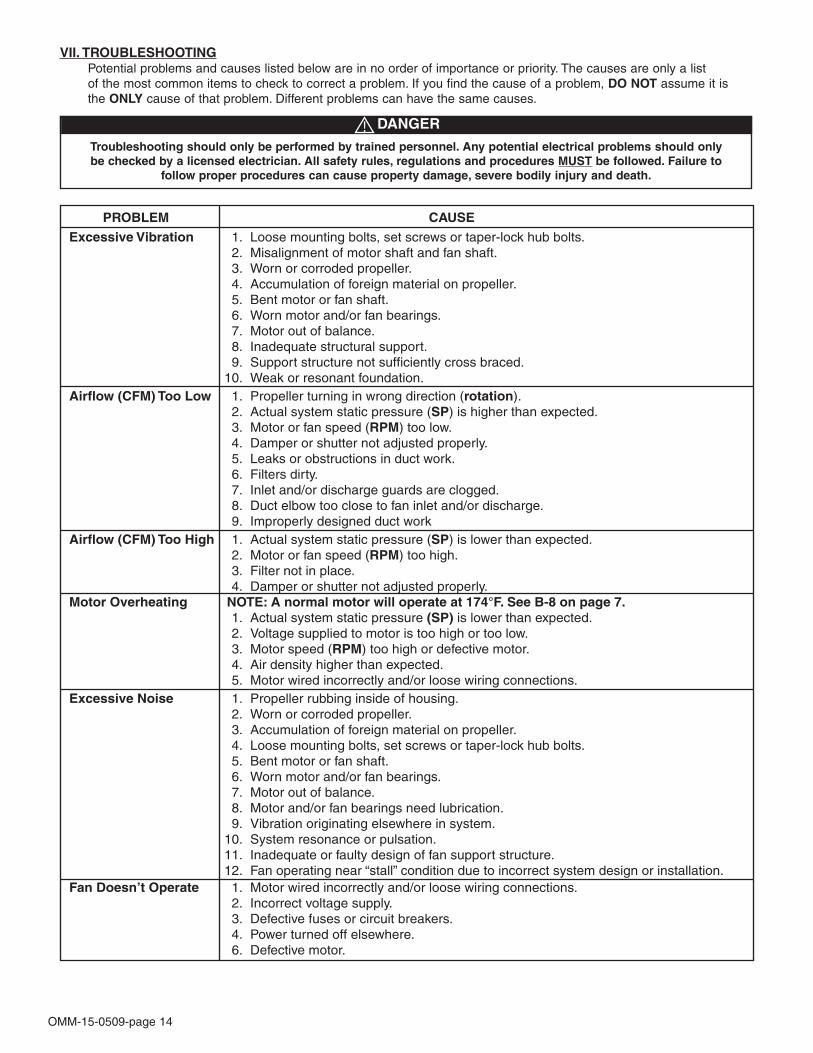
OMM-15-0509-page 14
Troubleshooting should only be performed by trained personnel. Any potential electrical problems should onlybe checked by a licensed electrician. All safety rules, regulations and procedures MUST be followed. Failure to
follow proper procedures can cause property damage, severe bodily injury and death.
DANGER
VII. TROUBLESHOOTINGPotential problems and causes listed below are in no order of importance or priority. The causes are only a listof the most common items to check to correct a problem. If you find the cause of a problem, DO NOT assume it isthe ONLY cause of that problem. Different problems can have the same causes.

OMM-15-0509-page 15
6. General Motor Procedure:
If the motor is not put into service immediately, the motor must be stored in a clean, dry, warm location. Minimumtemperature of 50°F. (10°C,). Several precautionary steps must be performed to avoid motor damage during storage.
a. Use a “Megger” each month to ensure that integrity of the winding insulation has been maintained. Recordthe Megger readings. Immediately investigate any significant drop in insulation resistance.
b. DO NOT lubricate the motor bearings during storage. Motor bearings are packed with grease at the factory.Excessive grease can damage the insulation quality in the motor.
c. If the storage location is damp or humid, the motor windings must be protected from moisture. This can bedone by applying power to the motor’s space heaters, (IF AVAILABLE) while the motor is in storage. If themotor does not have space heaters, storing it in a damp or humid location will, very quickly, cause internalcorrosion and motor failure which is not warranted.
d. Rotate motor shaft a minimum of 10 full turns each month to keep bearing grease from separating and dry-ing out.
NOTE:For specific storage instructions, for the actual motor and any accessory parts that were supplied, referto the manufacturer’s instructions.
VIII. LONG TERM STORAGE INSTRUCTIONS: (Storage exceeding 30 days after receipt of equipment)
NOTE: Failure to adhere to these instructions voids all warranties in their entirety.
1. Storage site selection:
(a) Level, well-drained, firm surface, in clean, dry and warm location. Minimum temperature of 50°F (10°C).(b) Isolated from possibility of physical damage from construction vehicles, erection equipment, etc.(c) Accessible for periodical inspection and maintenance.
2. The fan should be supported under each corner of its base to allow it to “breathe”. Supports (2 x 4’s, timbers, or rail-road ties) should be placed diagonally under each corner.
3. If the equipment is to be stored for more than three (3) months, the entire fan assembly must be loosely coveredwith plastic, but not tightly wrapped.
4. Initial inspections must be made of the fan components, and immediate corrective action taken if discrepancies arefound, to insure adequate protection of the equipment during storage.
(a) Sheave center distance should be reduced to reduce tension on the belts.
5. Storage Maintenance:
A periodic inspection and maintenance log, by date and action taken, must be developed and main-tained for each fan. See example below. Each item must be checked monthly.
EXAMPLE:
Storage / Maintenance Schedule Log

OMM-15-0509-page 16
DISCLAIMERThis manual, and all its content herein, is based on all applicable known material at the time this manual was created. Anyparts of this manual are subject to change at any time and without notice. If any statements, diagrams and/or instructions contained herein, for components not manufactured by the Seller, conflictwith instructions in the manufacturer’s manual (i.e.: motors, bearings, belts and sheaves, dampers, etc.), the instructions in themanufacturer’s manual, for that component take precedent.Should you want the latest version of this manual, please contact us or our sales office for your area. Or, you can print a currentversion by going to our website at: www.cincinnatifan.com
7697 Snider Road, Mason, OH 45040-9135Phone: (513) 573-0600 Fax: (513) 573-0640E-Mail: [email protected]
IX. LIMITED WARRANTY:Cincinnati Fan & Ventilator Company (Seller) warrants products of its own manufacture, against defects of material and workman-ship under normal use and service for a period of eighteen (18) months from date of shipment or twelve (12) months from date ofinstallation, whichever occurs first. This warranty does not apply to any of Seller’s products or any part thereof which has beensubject to extraordinary wear and tear, improper installation, accident, abuse, misuse, overloading, negligence or alteration. Thiswarranty does not cover systems or materials not of Seller’s manufacture. On products furnished by Seller, but manufactured byothers, such as motors, Seller extends the same warranty as Seller received from the manufacturer thereof. Expenses incurredby Purchaser’s in repairing or replacing any defective product will not be allowed except where authorized in writing and signedby an officer of the Seller.
The obligation of the Seller under this warranty shall be limited to repairing or replacing F.O.B. the Seller’s plant, or allowing creditat Seller’s option. THIS WARRANTY IS EXPRESSLY IN LIEU OF ALL OTHER WARRANTIES EITHER EXPRESSED ORIMPLIED INCLUDING THE WARRANTIES OF MERCHANTABILITY AND FITNESS FOR A PARTICULAR PURPOSE AND OFALL OTHER OBLIGATIONS AND LIABILITIES OF THE SELLER. THE PURCHASER ACKNOWLEDGES THAT NO OTHERREPRESENTATIONS WERE MADE TO PURCHASER OR RELIED UPON BY PURCHASER WITH RESPECT TO THE QUALI-TY OR FUNCTION OF THE PRODUCTS HEREIN SOLD.
Removal of the Sellers nameplate or any generic fan nameplate containing the fan serial number voids all warranties, either writ-ten or implied. Failure to complete and document all the pre-startup and post startup checks and perform the suggested routinemaintenance checks voids all warranties, either written or implied.
LIMITATION OF LIABILITY:Notice of any claim, including a claim for defect in material or workmanship, must be given to Seller in writing within 30 days afterreceipt of the equipment or other products. Seller reserves the right to inspect any alleged defect at Purchaser’s facility beforeany claim can be allowed and before adjustment, credit, allowance replacement or return will be authorized. See RETURNSbelow. Seller’s liability with respect to such defects will be limited to the replacement, free of charge, of parts returned atPurchaser’s expense F.O.B. Seller’s plant and found to be defective by the Seller.
IN NO EVENT WILL SELLER BE LIABLE FOR SPECIAL, INDIRECT, INCIDENTAL OR CONSEQUENTIAL DAMAGES,WHETHER IN CONTACT, TORT, NEGLIGENCE, STRICT LIABILITY OR OTHERWISE, INCLUDING WITHOUT LIMITATIONDAMAGES FOR INJURY TO PERSONS OR PROPERTY, LOST PROFITS OR REVENUE, LOST SALES OR LOSS OF USEOF ANY PRODUCT SOLD HEREUNDER. PURCHASER’S SOLE AND EXCLUSIVE REMEDY AGAINST SELLER WILL BETHE REPLACEMENT OF DEFECTIVE PARTS AS PROVIDED HEREIN OR REFUND OF THE PURCHASE PRICE FORDEFECTIVE PRODUCTS, AT SELLER’S SOLE OPTION. SELLER’S LIABILITY ON ANY CLAIM, WHETHER IN CONTRACT,TORT, NEGLIGENCE, STRICT LIABILITY OR OTHERWISE, FOR ANY LOSS OR DAMAGE ARISING OUT OF OR IN CON-NECTION WITH PURCHASER’S ORDER OR THE PRODUCTS OR EQUIPMENT PURCHASED HEREUNDER, SHALL IN NOCASE EXCEED THE PURCHASE PRICE OF THE EQUIPMENT GIVING RISE TO THE CLAIM.
RESPONSIBILITY:It is the understanding of the Seller that Purchaser and/or User will use this equipment in conjunction with additional equipmentor accessories to comply with all Federal, State and local regulations. The Seller assumes no responsibility for the Purchaser’sand/or User’s compliance with any Federal, State and local regulations.
RETURNS:Cincinnati Fan & Ventilator Company assumes no responsibility for any material returned to our plant without our permission. AnRMA (Return Material Authorization) number must be obtained and clearly shown on the outside of the carton or crate and on apacking slip. Any items returned must be shipped freight prepaid. Failure to comply will result in refusal of the shipment at ourreceiving department.

OMM-15-0509-page 17
X. PARTS DRAWING:
Cincinnati Fan manufactures many models and arrangements with special variations. For thatreason, the maintenance manuals contained on our website do not include a parts drawing nor thecompleted blower or fan specifications on page 1. For the parts drawing of all the standardcomponents and specifications for the specific blower or fan that you have, please contact our localCincinnati Fan sales office for your area.
You will need to give them the serial number shown on the blower or fan nameplate so they cansupply you the correct information.
Click on “Contact a Sales Rep” on our website for the name and contact information for our localsales office for your area. www.cincinnatifan.com
PLEASE NOTE