model transformations in the upes/upsoc development ... · e-mail: [email protected] p....
TRANSCRIPT

Innovations Syst Softw Eng (2009) 5:35–47DOI 10.1007/s11334-009-0080-9
ORIGINAL PAPER
Model transformations in the UPES/UPSoC development processfor embedded systems
Elvinia Riccobene · Patrizia Scandurra
Received: 1 September 2008 / Accepted: 12 January 2009 / Published online: 10 February 2009© Springer-Verlag London Limited 2009
Abstract Model-based development (MBD) aims at com-bining modeling languages with model transformers and codegenerators. Modeling languages, like profiles of the UnifiedModeling Language (UML), are increasingly being adoptedfor specific domains of interest to alleviate the complex-ity of platforms and express domain concepts effectively.Moreover, system development processes based on auto-matic model transformations are widely required to improvethe productivity and quality of the developed systems. In thispaper, we show how MBD principles and automatic modeltransformations provide the basis for the unified process forembedded systems (UPES) development process and its uni-fied process for system-on-chip (SoC) (UPSoC) subprocess.They have been defined to foster in a systematic and seam-less manner a model-based design methodology based onthe UML2 and UML profiles for the C/SystemC program-ming languages, which we developed to improve the currentindustrial system design flow in the embedded systems andsystem-on-chip area.
Keywords Model-based development (MBD) · Modeltransformations · Unified modeling language (UML) ·SystemC · Embedded system design
This work is supported in part by the project Model-drivenmethodologies and techniques for embedded systems design andanalysis based on UML, Abstract State Machines, and SystemC atSTMicroelectronics, AST R&I of Agrate Brianza (MI), Italy.
E. Riccobene (B)Dip. di Tecnologie dell’Informazione,Università di Milano, via Bramante 65, 26013 Crema (CR), Italye-mail: [email protected]
P. ScandurraDip. di Ingegneria dell’Informazione e Metodi Matematici,Università di Bergamo, Viale Marconi 5, 24044 Dalmine (BG), Italye-mail: [email protected]
1 Introduction
Model-based development (MBD) is an emerging paradigmin software production that combines domain-specific mod-eling languages (DSMLs) with model transformers, analyz-ers, and generators. Metamodel-based modeling languages,such as profiles or extensions of the Object ManagementGroup (OMG) standard Unified Modeling Language (UML),are increasingly being defined and adopted for specificdomains of interest (telecommunications, embedded systems,system-on-chip, real-time computing, aerospace, automotive,etc.), addressing the inability of third-generation languagesto alleviate the complexity of platforms and express domainconcepts effectively [35].
MBD emphasizes that software systems should bedesigned at a high abstraction level and then incrementallyrefined to contain more specific and detailed information,ending with the implementation of the system on a givenplatform. MBD principles propose the automation of parts ofthese refinements through automatic model transformationsin order to increase both the productivity and the quality ofthe developed systems. Model transformations are currentlya key research topic in the MBD context. The main researchinterest lies in vertical transformations, i.e., transformationsbetween models of different levels of abstraction such asthe platform-independent model (PIM) level, platform-spe-cific model (PSM) level, and code level of the OMG model-driven architecture (MDA) [17]. Another important aspect ishorizontal transformations, where models are translated intoother models at the same level of abstraction.
In [31], we presented a MBD-based methodology forembedded systems that we defined according to the platform-based design principles [15,45] and by exploiting the OMGMDA as a framework for MBD. The design methodology isbased on UML2, on a SystemC UML profile for the hardware
123
36 E. Riccobene, P. Scandurra
parts, and on a multithread C UML profile for the softwareparts. Both of the UML profiles are consistent sets of model-ing constructs designed to lift constructs (both structural andbehavioral) of the SystemC and C coding languages, respec-tively, to the UML modeling level. The design methodol-ogy, supported by a modeling environment, allows modelingof the system at higher levels of abstraction from a func-tional level to a register transfer level (RTL), handling boththe hardware architecture with the hardware-dependent soft-ware (HdS)—i.e. all software that is directly dependent onthe underlying hardware—and the (hardware-independent)application software. In [33], we presented the developmentprocess unified process for embedded systems (UPES), asan extension of the well-known software engineering uni-fied process (UP) [2] from the authors of the UML, to fos-ter our design methodology. UPES includes a subprocess,called the unified process for SoC (UPSoC), which combinesall involved notations together in a systematic and seamlessmanner for the HdS refinement flow.
In this paper, we show how the UPES/UPSoC processesare based on vertical and horizontal model transformationsfrom abstract models toward refined (but still abstract) mod-els and/or software code models. For the UPSoC subpro-cess, we show how well-established abstraction/refinementpatterns from hardware or system engineering and until nowonly used at code level, can be managed as model-to-modeltransformation steps and therefore applied at the UML level,by the use of the SystemC UML profile, along the model-ing process from a high-functional-level model down to aRTL model. We also show how MBD principles are appliedto provide the automation of model-to-code transformationsfrom abstract UML models toward detailed SystemC code.
The remainder of this paper is organized as follows.Sections 2 and 3 describe the design process UPES and itssubprocess UPSoC, respectively. Section 4 gives an over-view of the notations adopted in the UPSoC process, whileSect. 5 provides a brief description of the design environ-ment. Section 6 presents automatic model transformationsused in the UPSoC process. Section 7 provides some relatedwork. Section 8 concludes the paper and sketches some futuredirections of our contribution.
2 The unified process for ES (UPES)
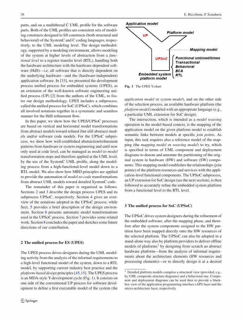
The UPES process drives designers during the UML model-ing activity from the analysis of the informal requirements toa high-level functional model of the system, down to a RTLmodel, by supporting current industry best practice and theplatform-based design principles [45,15]. The UPES processis an MDA-style Y-development cycle (Fig. 1). It consists onone side of the conventional UP process for software devel-opment to define a first executable model of the system (the
Fig. 1 The UPES Y-chart
application model or system model), and on the other sideof the selection process, an available hardware platform (theplatform model) modeled with an appropriate language (e.g.,a particular UML extension for SoC design).
The intersection, which is intended as a model weavingoperation in the model-based context, is the mapping of theapplication model on the given platform model to establishsemantic links between models at specific join points. Asinput, this task requires also a reference model of the map-ping (the mapping model or weaving model) to try, whichis specified in terms of UML component and deploymentdiagrams to denote and annotate the partitioning of the orig-inal system in hardware (HW) and software (SW) compo-nents. This mapping model establishes the relationships (joinpoints) of the platform resources and services with the appli-cation-level functional components. The UPSoC subprocess,an UP extension for SoC design (see the next section), is thenfollowed to accurately refine the embedded system platformfrom a functional level to the RTL level.
3 The unified process for SoC (UPSoC)
The UPSoC drives system designers during the refinement ofthe embedded software, after the mapping phase, and there-fore after the system components assigned to the HW par-tition have been mapped directly onto the HW resources ofthe selected platform. The UPSoC can also be adopted in astand-alone way also by platform providers to deliver offlinemodels of platforms1 by designing from scratch an abstracthardware platform—from the analysis of informal require-ments about the architecture elements (HW resources andprocessing elements)—or to directly design it at a desired
1 Detailed platform models comprise a structural view (provided, e.g.,by UML composite structure diagrams) and a behavioral one. Compo-nent and deployment diagrams can be used then to provide a black-box view of the application programming interface (API) layer and themicro-architecture layer, respectively.
123
Model transformations in the UPES/UPSoC development process for embedded systems 37
level of abstraction. The model of this generic platform couldthen be reused and targeted accordingly to implement a spe-cific hardware platform on which to embed a given system.In both cases, by using, e.g., the UML profile for SystemC[30,34] that provides in a graphical way all modeling ele-ments for the design of the hardware components, the hard-ware platform can be modeled at different abstraction levels:functional untimed/timed, transactional (TLM), behavioral,bus cycle accurate, and RTL (Fig. 1).
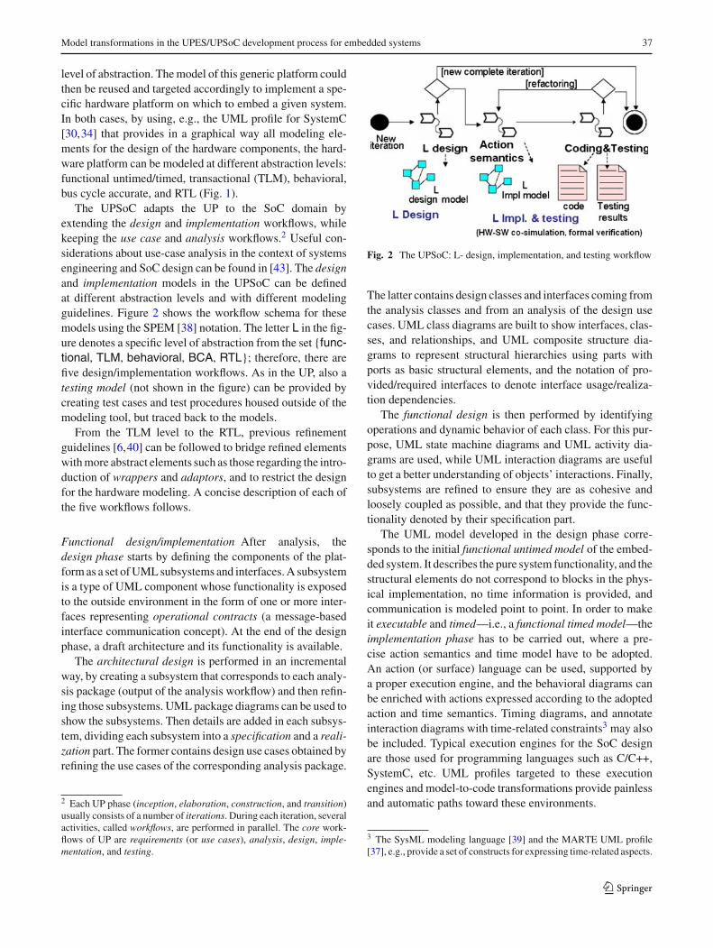
The UPSoC adapts the UP to the SoC domain byextending the design and implementation workflows, whilekeeping the use case and analysis workflows.2 Useful con-siderations about use-case analysis in the context of systemsengineering and SoC design can be found in [43]. The designand implementation models in the UPSoC can be definedat different abstraction levels and with different modelingguidelines. Figure 2 shows the workflow schema for thesemodels using the SPEM [38] notation. The letter L in the fig-ure denotes a specific level of abstraction from the set {func-tional, TLM, behavioral, BCA, RTL}; therefore, there arefive design/implementation workflows. As in the UP, also atesting model (not shown in the figure) can be provided bycreating test cases and test procedures housed outside of themodeling tool, but traced back to the models.
From the TLM level to the RTL, previous refinementguidelines [6,40] can be followed to bridge refined elementswith more abstract elements such as those regarding the intro-duction of wrappers and adaptors, and to restrict the designfor the hardware modeling. A concise description of each ofthe five workflows follows.
Functional design/implementation After analysis, thedesign phase starts by defining the components of the plat-form as a set of UML subsystems and interfaces. A subsystemis a type of UML component whose functionality is exposedto the outside environment in the form of one or more inter-faces representing operational contracts (a message-basedinterface communication concept). At the end of the designphase, a draft architecture and its functionality is available.
The architectural design is performed in an incrementalway, by creating a subsystem that corresponds to each analy-sis package (output of the analysis workflow) and then refin-ing those subsystems. UML package diagrams can be used toshow the subsystems. Then details are added in each subsys-tem, dividing each subsystem into a specification and a reali-zation part. The former contains design use cases obtained byrefining the use cases of the corresponding analysis package.
2 Each UP phase (inception, elaboration, construction, and transition)usually consists of a number of iterations. During each iteration, severalactivities, called workflows, are performed in parallel. The core work-flows of UP are requirements (or use cases), analysis, design, imple-mentation, and testing.
Fig. 2 The UPSoC: L- design, implementation, and testing workflow
The latter contains design classes and interfaces coming fromthe analysis classes and from an analysis of the design usecases. UML class diagrams are built to show interfaces, clas-ses, and relationships, and UML composite structure dia-grams to represent structural hierarchies using parts withports as basic structural elements, and the notation of pro-vided/required interfaces to denote interface usage/realiza-tion dependencies.
The functional design is then performed by identifyingoperations and dynamic behavior of each class. For this pur-pose, UML state machine diagrams and UML activity dia-grams are used, while UML interaction diagrams are usefulto get a better understanding of objects’ interactions. Finally,subsystems are refined to ensure they are as cohesive andloosely coupled as possible, and that they provide the func-tionality denoted by their specification part.
The UML model developed in the design phase corre-sponds to the initial functional untimed model of the embed-ded system. It describes the pure system functionality, and thestructural elements do not correspond to blocks in the phys-ical implementation, no time information is provided, andcommunication is modeled point to point. In order to makeit executable and timed—i.e., a functional timed model—theimplementation phase has to be carried out, where a pre-cise action semantics and time model have to be adopted.An action (or surface) language can be used, supported bya proper execution engine, and the behavioral diagrams canbe enriched with actions expressed according to the adoptedaction and time semantics. Timing diagrams, and annotateinteraction diagrams with time-related constraints3 may alsobe included. Typical execution engines for the SoC designare those used for programming languages such as C/C++,SystemC, etc. UML profiles targeted to these executionengines and model-to-code transformations provide painlessand automatic paths toward these environments.
3 The SysML modeling language [39] and the MARTE UML profile[37], e.g., provide a set of constructs for expressing time-related aspects.
123

38 E. Riccobene, P. Scandurra
Transactional design/implementation At the TLM level, thearchitecture is designed and validated in terms of function-ality as characterized by high-level block input and outputevents, and interblock data transfers. Communication detailsamong processing elements are separated from the detailsof computation. Communication is modeled by channels,while transaction requests take place by calling interfacefunctions of these channel elements. Transactions are pro-tocols exchanging abstract data between blocks, with asso-ciated timing information. Elements of a TLM model cancorrespond or not to blocks in the physical implementation.Channels’ interfaces encapsulate low-level details to enablehigher simulation speed than pin-based interfaces and alsoto speed up the modeling task.
The SoC architecture is designed with Intellectual Prop-erty (IP) blocks connected via application program interfaces(APIs) to implementation-independent high-level bus mod-els. System IP components and buses may be modified orreplaced with greater ease than at RTL, and simulated morethan 1,000 times faster. Thus designers can quickly optimizethe design to achieve what works best.
To make a transactional model executable (implementa-tion model), UML profiles for languages such as SpecC andSystemC supporting the transaction-level model can be con-sidered. Similar considerations apply to the next levels.
Behavioral design/implementation A behavioral model ispin-accurate and functionally accurate at its boundaries. It isnot cycle accurate, i.e., internal and input/output (I/O) eventsare not scheduled in a cycle-accurate manner. There is a cer-tain freedom left to implement the model in a certain numberof clock cycles.
BCA design/implementation A bus-cycle-accurate model ispin-accurate and functionally accurate. It is also cycle-accu-rate at its boundaries, i.e., in the number of clock cycles ittakes to perform its functionality (I/O interactions are sched-uled at the proper clock cycle; internal events are not sched-uled).
RTL design/implementation At RTL level the hardware isdescribed in terms of transfers among registers thoughfunctional units like adders, multipliers, arithmetic logic units(ALUs), etc. The RTL model is accurate at the clock cyclelevel, both at the boundaries and internally (all actions arescheduled at the appropriate clock cycle), and also pin-accu-rate.
The RTL platform model serves as input to the lower-levelvery-large-scale integration (VLSI) design flow, where logicsimulation and synthesis are performed, leading to the finalproduct.
4 UPSoC notations
A brief overview is provided here of the two main notationsadopted in the UpSoC subprocess: the SystemC coding lan-guage as the target language of the model-to-code transfor-mations, and the SystemC UML profile as the main modelingnotation used at different levels of abstractions and, there-fore, source/target language of the model-to-model transfor-mations.
4.1 SystemC overview
SystemC [1,21] is an IEEE standard controlled by the majorcompanies in the electronic design automation (EDA) indus-try. It is a system-level design language intended to supportthe description and validation of complex systems in an envi-ronment completely based on the C++ programming lan-guage.
SystemC is defined in terms of a C++ class library, orga-nized according to a layered architecture, shown in Fig. 3(taken from [40]). The core language and data types are theso-called core layer (or layer 0) of the standard SystemC,and consist of the event-based and discrete-timed SystemCsimulation kernel, the core design primitives and data types.The primitive channels represents, instead, the layer 1 of Sy-stemC; it comes with a predefined set of interfaces, ports andchannels for commonly used communication mechanismssuch as signals and FIFOs. Finally, the external libraries layeron top of the layer 1 are not considered as part of the standardSystemC language.
Figure 4 depicts a simplified metamodel (an abstract syn-tax provided in terms of a class diagram) of the main SystemCterms and concepts. The design of a system in SystemC isessentially given by a containment hierarchy of modules. Amodule is a container class able to encapsulate structure andfunctionality of hardware/software blocks. Each module may
Fig. 3 SystemC language architecture
123

Model transformations in the UPES/UPSoC development process for embedded systems 39
Fig. 4 A simplified SystemC metamodel
contain variables as simple data members, ports for commu-nication with the surrounding environment and processes forperforming module’s functionality and expressing concur-rency in the system. Two kinds of processes are available:method processes and thread processes. They run concur-rently in the design and may be sensitive to events which arenotified by other processes. A port of a module is a proxyobject through which the process accesses a channel inter-face. The interface defines the set of access functions for achannel, while the channel provides the implementation ofthese functions to serve as a container to encapsulate the com-munication of blocks. There are two kinds of channels: prim-itive channels and hierarchical channels. Primitive channelsdo not exhibit any visible structure, do not contain processes,and cannot (directly) access other primitive channels. A hier-archical channel is a module, i.e., it can have structure, it cancontain processes, and it can directly access other channels.
In 2006, SystemC received a major revision (2.2) andbecame an IEEE standard [1]. This last revision includesnew structural and behavioral features for transaction-levelmodeling (TLM) according to the Open SystemC Initiative(OSCI) TLM standard.
4.2 The SystemC UML profile
The UML2 profile for SystemC [34] is a consistent set ofmodeling constructs designed to lift both structural andbehavioral constructs of the SystemC coding language(including events and time features) to the UML modelinglevel.
A UML2 profile is a set of stereotypes. Each stereotypedefines how the syntax and the semantics of an existingUML2 construct (a class of the UML2 metamodel) isextended for a specific domain terminology or purpose. Astereotype can define additional semantic constraints—thewell-formedness rules expressed in the object constraint lan-guage (OCL) [20] over the base metaclass—to enforce asemantic restriction of the extended modeling element, aswell as tags to state additional properties. Figure 5 shows anexample of stereotype definition for the SystemC sc_porttogether with an example of OCL constraint. At model level,
Fig. 5 sc_port stereotype
Fig. 6 Modules, ports, and interfaces
when a stereotype is applied to a model element (an instanceof a UML metaclass), an instance of a stereotype is linked tothe model element. From a notational point of view, the nameof the stereotype is shown within a pair of guillemets aboveor before the name of the model element and the eventualtagged values displayed inside or close as name–value pairs.Examples of stereotypes application are provided here (seeFig. 6, e.g., for the sc_port stereotype) and in Sect. 6.1.
The SystemC UML profile is defined at two distinctlevels—the SystemC core layer (or layer 0) and theSystemC layer of predefined channels, ports and interfaces(or layer 1)—reflecting the layered architecture of SystemC.
The core layer—the basic SystemC profile—is the foun-dation upon which specific libraries of model elements oralso other modeling constructs can be defined. It is logicallystructured as follows.
A structure and communication part defines stereotypesfor the SystemC building constructs (modules, interfaces,ports, and channels) for use in UML structural diagrams suchas UML class diagrams and composite structure diagrams.UML class diagrams are used to define modules, interfaces,and channels. Figure 6 shows an example of a SystemC mod-ule exposing a multi-port, an array port, and a simple port,together with the port type and the interface definitions ofthe simple port.
The internal structure of composite modules, especiallyof the topmost-level module (representing the structure ofthe overall system), is captured by UML composite struc-ture diagrams. From these diagrams several UML objectdiagrams can be created to describe different configurationscenarios. This separation allows the (also partial) specifi-cation of different HW platforms as instances of the same
123

40 E. Riccobene, P. Scandurra
Fig. 7 A thread process pattern
parametric model (i.e., the composite structure diagram).Concrete examples of composite modules are provided inSect. 6.1.
A behavior and synchronization part defines special stateand action stereotypes which lead to an extension of the UMLstate machines, the SystemC process state machines [29].This formalism has been appositely included in the profiledefinition to model the control flow and the reactive behaviorof SystemC processes (methods and threads) within mod-ules. A finite number of abstract behavior patterns of statemachines have been identified. Figure 7 depicts one of thesebehavior patterns together with the corresponding SystemCpseudocode for a thread that: (i) is not initialized, (ii) has botha static (the event list e1s, . . . , eNs) and a dynamic sensitivity(the wait state), and (iii) runs continuously (by the infinitewhile loop). Note that the notation used for the wait statein the pattern in Fig. 7 stands for a shortcut to represent ageneric wait(e*) call where the event e* matches one ofthe cases reported in Fig. 8. Moreover, activities a1 and a2stand for blocks of sequential (or not) code without waitstatements.
It should be noted that the state machine pattern depicted inFig. 7 can be more complex if one or more wait statementsare enclosed in the scope of one or more nested control struc-tures. In this case, as part of the UML profile for SystemC, thecontrol structures while, if, etc. need to be explicitly rep-resented in terms of special stereotyped junction or choicepseudostates4 combined together in order to stand out thestate-like representation of the wait calls. The conditionalcontrol and loop controls, e.g., can be modeled as shown inFigs. 9 and 10, respectively. These stereotypes allow us togenerate code effectively from state diagrams in a style thatreflects the nature of constructs of the target implementationlanguage, despite well-know techniques (such as state pat-tern, stable table pattern, etc.) currently used to achieve thisgoal.
4 Choice pseudostates must be used in place of junction pseudostateswhenever the head condition of the while loop is a function of theresults of prior actions performed in the same run-to-completion step.
Fig. 8 Dynamic sensitivity of a thread
Fig. 9 Conditional controls
A data types part defines a UML class library to representthe set of SystemC data types.
In addition, predefined channels, ports, and interfaces oflayer 1 of SystemC are provided either as a UML class library,modeled with the basic stereotypes of the SystemC corelayer, or as a group of stand-alone stereotypes—the extendedSystemC profile—specializing the basic profile.
An extended version of the SystemC UML profile encap-sulating some new structural and behaviural features
123

Model transformations in the UPES/UPSoC development process for embedded systems 41
Fig. 10 Loop controls
Fig. 11 Tool architecture
(i.e., dynamic processes and fork/join synchronization mech-a-nisms) necessary to model a TLM library conforming tothe OSCI SystemC TLM library was presented in [3].
5 UPSoC design tool
For industrial application, the availability of appropriate toolsupport is crucial. In order to cover the full spectrum ofUPSoC by using C/C++ and SystemC as action languages,we developed a design tool working as front-end for consol-idated lower-level co-design tools.
Figure 11 shows the tool architecture. Components visu-alized inside dashed lines are still under development. Thetool consists of two major parts: a development kit (DK) withdesign and development components, and a runtime environ-ment (RE) represented by the SystemC execution engine.
The DK consists of a UML2 modeler supporting theSystemC UML profile, translators for the forward/reverseengineering to/from C/C++/SystemC, and an abstraction/refinement evaluator to guarantee traceability and correct-ness along the refinement process from the high-level abstractdescription to the final implementation. A more detaileddescription of the tool is provided in [32].
Initially, the UML2 modeler was based on the commercialEnterprise Architect (EA) tool [10] by SparxSystems. Fig-ure 12 shows a screenshot of EA. The SystemC data typesand predefined channels, interfaces, and ports are modeledwith the core stereotypes, and are available in the projectview with the name SystemC_Layer1.
Recently, we have implemented the UML2 modeler alsoin the Papyrus framework [23], an open-source Eclipse-basedUML modeler which supports the UML2 standard as definedby the OMG and allows the integration of model transfor-mation services. The latter are handled by transformationengines, such as the ATL engine [13] (the one we adopted),developed within the Eclipse Modeling Project [12] asimplementation of the OMG Queries–Views–Transforma-tions (QVT) [27] standard.
6 UPSoC model transformations
The MDA-style separation of models of UPES/UPSoCdemands automatic model transformations as support toevolution activities [18] in general, such as refinement/abstraction, model refactoring, model inconsistency manage-ment, etc.
According to the classification given in [8], for refine-ment/abstraction purposes we identify two main kinds ofmodel transformations to be adopted specifically in theUPSoC process: model-to-model transformations and model-to-code transformations. They are better explained in thefollowing sections by providing concrete examples.
6.1 Model-to-model transformations
Model-to-model transformations of UPSoC allow modelrefinement along the (not necessarily successive) abstractionlevels: functional, transactional, behavioral, BCA, and RTL.These transformations must be intended as vertical transfor-mations as they imply a change of the level of abstraction.Each model is here intended as an instance of the SystemCUML profile metamodel, and therefore is an implementationmodel with a fixed action semantics.
In the model-to-model category, we adopt a hybridapproach based on both direct manipulation and structure-driven approach [8]. The idea is to collect and reuse preciseabstraction/refinement transformation patterns, coming fromindustry best practices. The transformation patterns are onceand for all proved correct and complete, and can be used toguide the refinement process or to point out missing elementsin a refinement.
We have implemented some of these patterns in theEA-based environment by using the EA MDA transform-ers, and in the Papyrus-based environment using the ATLengine. By applying the model transformations defined for a
123

42 E. Riccobene, P. Scandurra
Fig. 12 Generate SystemCcode from EA
given pattern, a UML system design may automatically andcorrectly evolve to an abstract/refined model reflecting theabstraction/refinement rules defined for the applied pattern.Below, we provide an example of communication refinementfrom functional level to RTL level based on model transfor-mations.
6.1.1 Communication refinement
In general, in the refinement process we do not only refine themodel’s internal structure, its timing, or the data types beingused; we also need to think about how components com-municate with their environment. Communication refinementrefers to mapping an abstract communication protocol intoan actual implementation related to a given target architec-ture. To give an idea on how to perform refinement at UMLlevel by model-to-model transformations, we show here howto apply communication refinement patterns to a functionaltimed model leading to a RTL model.
We clarify the process of communication refinement in ageneral way. To this purpose, we assume to have two high-level modules M1 and M2 communicating over a channel Cvia some abstract protocol. As suggested in [40], one possi-ble approach to refining this basic communication scenariotoward an implementation consists of the following steps:
1. Select an appropriate communication scheme toimplement
2. Replace the abstract communication channel C with arefined one CRefined realizing the selected communica-tion protocol
3. Enable the communication of the modules M1 and M2over CRefined by either:
(a) wrapping CRefined in a way that the resulting chan-nel CWrapped provides the interfaces required by M1and M2 (wrapping) or
(b) refining M1 into M1Refined and M2 into M2Refined
in order their required interfaces match the onesprovided by CRefined (adapter-merging)
The two cases (not the only ones) are similar. Both includean intermediate step to build two further modules—i.e., twohierarchical channels called adapters—to map one interfaceto another: one, let us say A1, between M1 and CRefined, andone, let us say A2, between CRefined and M2. In case (a),the resulting channel CWrapped encloses CRefined and the twoadapters, while in case (b) these adapters are merged to thecalling modules M1 and M2, resulting in the refined modulesM1Refined and M2Refined. Deciding whether to use wrappingor merging depends on the methodology and chosen targetarchitecture.
Example We show here how to apply the described com-munication refinement strategy to a simple abstract (func-tional timed) producer/consumer system taken from [40].
123

Model transformations in the UPES/UPSoC development process for embedded systems 43
Fig. 13 A producer/consumerdesign
Fig. 14 Producer/consumermodules communicating via aprimitive FIFO
Fig. 15 Clocked RTL HWFIFO
The design of a producer/consumer module that writes andreads characters to/from a FIFO channel is shown by theUML composite structure diagram in Fig. 13. The top com-posite module is defined to contain one instance of the con-sumer module, one instance of the producer module, and oneFIFO channel instance. The FIFO channel permits to storecharacters by means of blocking read and write interfaces,such that characters are always reliably delivered. Two pro-cesses, the producer and the consumer (see the thread pro-cesses main within the producer and the consumer modulesin Fig. 14), respectively, feed and read the FIFO. The pro-ducer module writes data through its out port into the FIFOby a sc_fifo_out_if interface, and the consumer module readsdata from the FIFO through its in port by the sc_fifo_in_ifinterface. These two interfaces are implemented by the FIFOchannel (see the sc_fifo channel in Fig. 14). Because of theblocking nature of the sc_fifo read/write operations, all dataare reliably delivered despite the varying rates of productionand consumption.
Now, let us assume that the (abstract) FIFO instance aboveis replaced with a (refined) model of a clocked RTL hard-
ware FIFO named hw_fifo<T> for an hardware implementa-tion. The new hardware FIFO uses a signal-level ready/validhandshake protocol for both the FIFO input and output(Fig. 15). It should be noted that we cannot use hw_fifodirectly in place of sc_fifo, since the former does not provideany interfaces at all, but has ports that connect to signals, i.e.,has ports that use the sc_signal_in_if and sc_signal_out_ifinterfaces.
Following the wrapper-based approach (3b) describedabove, we can define a hierarchical channel hw_fifo_wrapper<T> (CWrapped) implementing the interfaces sc_fifo_out_if and sc_fifo_in_if and containing an instance ofhw_fifo<T> (CRefined). In addition, it contains sc_signalinstances to interface with hw_fifo<T> and a clock port(since hw_fifo<T> has also a clock port) to feed in the clocksignal to the hw_fifo<T> instance (Fig. 16). Finally, we needto add a hardware clock instance in the top-level design todrive the additional clock port that is now on the hw_fifo_wrapper<T> instance (Fig. 17). The hw_fifo_wrapper<T>implements the required signal-level ready/valid handshakeprotocol whenever a read or write operation occurs; this
123

44 E. Riccobene, P. Scandurra
Fig. 16 The hw_fifo_wrapper hierarchical channel
Fig. 17 A clockedproducer/consumer design
protocol will properly suspend read or write transactions ifhw_fifo<T> is not ready to complete the operation. Detailson the SystemC code can be found in [40].
6.2 Model-to-code transformations
Model-to-code transformations are primarily aimed at pro-viding executable models at a fixed abstraction level. Theymust be intended as horizontal transformations creating pro-gram text in the SystemC implementation language.
In the model-to-code category, we distinguish betweenvisitor- and template-based approaches. Visitor-based sim-ply means that the model is navigated and code is generatedfor each element visited according to specific rules describ-ing for each metaconcept what code to generate and whichelements to visit next. Template-based approaches use targettext that includes place holders that are to be replaced withconcrete data in concrete template instances. Rules in suchtemplate-based approaches usually access information in thesource model using the left-hand side of a rule and give atemplate as right-hand side that incorporates this data in apiece of target code.
We adopted a visitor-based approach for the EA-basedenvironment. The EA supports forward/reverse engineering
to/from C++. We developed an EA add-in (based on the EAautomation and scripting interface and on the Windows OLEAutomation ActiveX technology) which exploits the addedsemantics in the SystemC UML profile to generate completeSystemC code (full code generation) from input models (forboth the structural and behavioral views) developed with theEA-based UML modeler.
The EA-based code generator traverses all class diagramsand for every encountered class it produces a C++ header file(.h); this happens for both the definition of SystemC classes(modules, channels, and interfaces) and simple C++ clas-ses, allowing a mixed design style. Classes contain fieldsand methods. For each method it is possible to describe itsbehavior either as an inline code description or as a SystemCprocess state machine diagram. Each process state machine,therefore, contributes to the generation and enrichment of abody file (.cpp) containing the implementation code of allmethods of a class or module or channel.
Moreover, by an analysis of the composite structure dia-gram associated to a module to describe its internal struc-ture (especially the one of the topmost-level module, whichrepresents the structure of the overall system), it is possibleto determine how internal parts are connected to each otherin the module constructors in the header file. Finally, object
123
Model transformations in the UPES/UPSoC development process for embedded systems 45
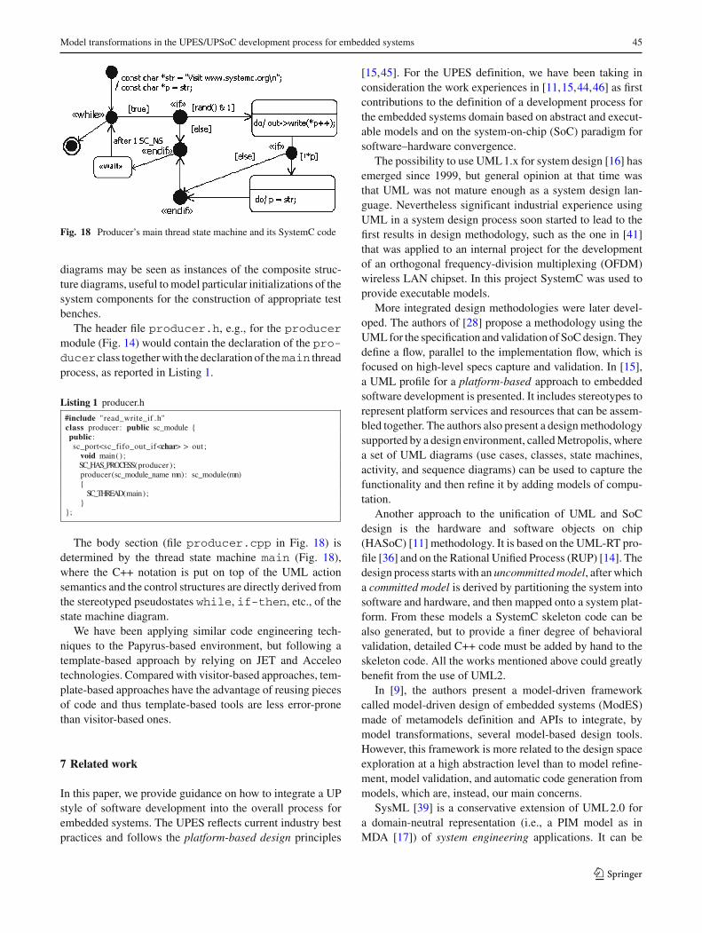
Fig. 18 Producer’s main thread state machine and its SystemC code
diagrams may be seen as instances of the composite struc-ture diagrams, useful to model particular initializations of thesystem components for the construction of appropriate testbenches.
The header file producer.h, e.g., for the producermodule (Fig. 14) would contain the declaration of the pro-ducer class together with the declaration of themain threadprocess, as reported in Listing 1.
Listing 1 producer.h
#include "read_write_if .h"class producer : public sc_module {public :sc_port<sc_fifo_out_if<char> > out ;
void main( ) ;SC_HAS_PROCESS(producer ) ;producer(sc_module_name mn): sc_module(mn){
SC_THREAD(main) ;}
};
The body section (file producer.cpp in Fig. 18) isdetermined by the thread state machine main (Fig. 18),where the C++ notation is put on top of the UML actionsemantics and the control structures are directly derived fromthe stereotyped pseudostates while, if-then, etc., of thestate machine diagram.
We have been applying similar code engineering tech-niques to the Papyrus-based environment, but following atemplate-based approach by relying on JET and Acceleotechnologies. Compared with visitor-based approaches, tem-plate-based approaches have the advantage of reusing piecesof code and thus template-based tools are less error-pronethan visitor-based ones.
7 Related work
In this paper, we provide guidance on how to integrate a UPstyle of software development into the overall process forembedded systems. The UPES reflects current industry bestpractices and follows the platform-based design principles
[15,45]. For the UPES definition, we have been taking inconsideration the work experiences in [11,15,44,46] as firstcontributions to the definition of a development process forthe embedded systems domain based on abstract and execut-able models and on the system-on-chip (SoC) paradigm forsoftware–hardware convergence.
The possibility to use UML 1.x for system design [16] hasemerged since 1999, but general opinion at that time wasthat UML was not mature enough as a system design lan-guage. Nevertheless significant industrial experience usingUML in a system design process soon started to lead to thefirst results in design methodology, such as the one in [41]that was applied to an internal project for the developmentof an orthogonal frequency-division multiplexing (OFDM)wireless LAN chipset. In this project SystemC was used toprovide executable models.
More integrated design methodologies were later devel-oped. The authors of [28] propose a methodology using theUML for the specification and validation of SoC design. Theydefine a flow, parallel to the implementation flow, which isfocused on high-level specs capture and validation. In [15],a UML profile for a platform-based approach to embeddedsoftware development is presented. It includes stereotypes torepresent platform services and resources that can be assem-bled together. The authors also present a design methodologysupported by a design environment, called Metropolis, wherea set of UML diagrams (use cases, classes, state machines,activity, and sequence diagrams) can be used to capture thefunctionality and then refine it by adding models of compu-tation.
Another approach to the unification of UML and SoCdesign is the hardware and software objects on chip(HASoC) [11] methodology. It is based on the UML-RT pro-file [36] and on the Rational Unified Process (RUP) [14]. Thedesign process starts with an uncommitted model, after whicha committed model is derived by partitioning the system intosoftware and hardware, and then mapped onto a system plat-form. From these models a SystemC skeleton code can bealso generated, but to provide a finer degree of behavioralvalidation, detailed C++ code must be added by hand to theskeleton code. All the works mentioned above could greatlybenefit from the use of UML2.
In [9], the authors present a model-driven frameworkcalled model-driven design of embedded systems (ModES)made of metamodels definition and APIs to integrate, bymodel transformations, several model-based design tools.However, this framework is more related to the design spaceexploration at a high abstraction level than to model refine-ment, model validation, and automatic code generation frommodels, which are, instead, our main concerns.
SysML [39] is a conservative extension of UML 2.0 fora domain-neutral representation (i.e., a PIM model as inMDA [17]) of system engineering applications. It can be
123
46 E. Riccobene, P. Scandurra
involved at the beginning of the design process, in placeof the UML, for the requirements, analysis, and functionaldesign workflows. So it is in agreement with our UML pro-file for SystemC, which can be thought of (and effectivelymade) as customization of SysML rather than UML. Unluck-ily, when we started, the SysML specification was not yetfinalized and there were no tools yet supporting it. Similarconsiderations apply also to the recent modeling and analysisof real-time embedded systems (MARTE) profile initiative[37].
The standardization proposal [42] by Fujitsu, in collabo-ration with IBM and NEC, has evident similarities with ourSystemC UML profile, such as the choice of SystemC as atarget implementation language. However, their profile doesnot provide building blocks for behavior modeling and anytime model.
Some other proposals already exist for extensions of UMLtowards C/C++/SystemC. All have in common the use ofUML stereotypes for SystemC constructs, but do not relyon a UML profile definition. In this sense, the work in [5]attempting to define a UML profile for SystemC is appre-ciable; but, as with all the other proposals, it is based on theprevious version of UML (UML 1.4). Moreover, in all theproposals we have seen, except in [19], no code generationfrom behavioral diagrams is considered.
Refinement, or in general model-to-model transformation,is another key concept in MBD. However, compared with therefinement techniques available for formal methods such asZ, B, and Abstract State Machines (ASMs) [4], little workhas been carried out for modeling languages such as UML.Some proposals that we are considering in our process canbe found in [7,22,24–26].
8 Conclusions and future directions
This paper describes aspects of reusable model-to-model andmodel-to-code transformations in the context of the UPES/UPSoC processes for embedded system development. Thisaspect is vital for integrating, synchronizing or transformingmodels for our design methodology based on the UPES/UP-SoC processes.
Today, model transformations are mainly written fromscratch. This is in many cases a very time-consuming anddifficult task. According to the MBD vision, there must belarge libraries of reusable model transformations available.
In the future, we aim to identify characteristics of reusabletransformations and ways of achieving reuse by collecting ina library precise abstraction/refinement transformation pat-terns according to the levels of abstraction: functional, trans-actional, behavioral, BCA, and RTL. In particular, we arefocusing on the TLM to model the communication aspectsat a certain number of TLM sublevels according to the OSCI
TLM 1.0 library [21]. We believe that the use of fine-grainedtransformations that are being composed (chaining) wouldbe beneficial for increasing both the productivity and qualityof the developed systems.
References
1. SystemC Language Reference Manual (2006). IEEE Std 1666-2005, 31 March 2006
2. Arlow J, Neustadt I (2002) UML and the unified process. Addi-son-Wesley, Reading
3. Bocchio S, Riccobene E, Rosti A, Scandurra P (2008) An enhancedsystemc uml profile for modeling at transaction-level. In: Villar E(ed) Embedded systems specification and design languages
4. Börger E, Stärk R (2003) Abstract state machines: a method forhigh-level system design and analysis. Springer, Berlin
5. Bruschi F, Sciuto D (2002) SystemC based design flow startingfrom UML model. In: Proceedings of European SystemC usersgroup meeting
6. Cai L, Gajski D (2003) Transaction level modeling: an overview. In:Proceedings of CODES+ISSS, Newport Beach, California, USA
7. The Catalysis Process (1998). http://www.catalysis.org8. Czarnecki K, Helsen S (2003) Classification of model transforma-
tion approaches. In: Proceedings of 2nd OOPSLA workshop ongenerative techniques in the context of model-driven architecture
9. do Nascimento FAM, Oliveira MFS, Wagner FR (2007) ModES:embedded systems design methodology and tools based on MDE.In: Fourth International workshop on Model-based Methodologiesfor Pervasive and Embedded Software (MOMPES’07). IEEE Press(2007)
10. The Enterprise Architect Tool (2008). http://www.sparxsystems.com.au/
11. Edwards M, Green P (2003) UML for hardware and software objectmodeling. UML for real design of embedded real-time systems,pp 127–147
12. Eclipse Modeling Framework (2008). http://www.eclipse.org/emf/13. Jouault F, Allilaire F, Bézivin J, Kurtev I, Valduriez P (2006)
ATL: a QVT-like transformation language. In: OOPSLA ’06: com-panion to the 21st ACM SIGPLAN conference on Object-ori-ented programming systems, languages, and applications. ACM,pp 719–720
14. Kruchten P (1999) The rational unified process. Addison-Wesley,Reading
15. Lavagno L, Martin G, Sangiovanni Vincentelli A, Rabaey J, ChenR, Sgroi M (2003) UML and platform based design. UML for realdesign of embedded real-time systems
16. Martin G (1999) UML and VCC. White paper, Cadence DesignSystems, Inc, Dec.
17. OMG (2003) The Model Driven Architecture (MDA). MDA GuideV1.0.1, http://www.omg.org/mda/
18. Mens T, Wermelinger M, Ducasse S, Demeyer S, Hirschfeld R,Jazayeri M (2005) Challenges in software evolution. In: Proceed-ings of the international workshop on software evolution. IEEE
19. Nguyen KD, Sun Z, Thiagarajan PS, Wong WF (2005) Model-driven SoC design: the UML-SystemC bridge. UML for SOCDesign
20. OMG. UML 2.0 OCL Specification, ptc/03-10-1421. The Open SystemC Initiative (2008). http://www.systemc.org22. Paige RF, Kolovos DS, Polack FAC (2005) Refinement via consis-
tency checking in MDA. In: Proceedings Refinement Workshop,ENTCS, Surrey, UK, April
23. Papyrus UML Web Site http://www.papyrusuml.org (2008)
123

Model transformations in the UPES/UPSoC development process for embedded systems 47
24. Pons C, Kutsche R-D (2003) Using UML-B and U2B for formalrefinement of digital components. In: Proceedings of forum onspecification and design languages, Frankfurt
25. Pons C, Kutsche R-D (2004) Traceability across refinement steps inUML modeling. In: Proceedings of the WiSME@UML workshop
26. Pons C, Garcia D (2006) An OCL-based technique for specify-ing and verifying refinement-oriented transformations in MDE.In: MoDELS, pp 646–660
27. OMG (2007) MOF Query/Views/Transformations, ptc/07-07-0728. Zhu Q, Oishi R, Hasegawa T, Nakata T (2004) System-on-chip
validation using UML and CWL. In: Proceedings of CODES29. Riccobene E, Scandurra P (2004) Modelling systemc process
behaviour by the UML method state machines. In: Proceedingsof RISE’04. Springer, Heidelberg
30. Riccobene E, Scandurra P, Rosti A, Bocchio S (2005) A UML2.0 profile for SystemC: toward high-level SoC design. In: EM-SOFT ’05: Proceedings of the 5th ACM international conferenceon embedded software. ACM Press, pp 138–141
31. Riccobene E, Scandurra P, Rosti A, Bocchio S (2006) A model-driven co-design flow for embedded systems. In: FDL ’06: Pro-ceedings of forum on specification and design languages
32. Riccobene E, Scandurra P, Rosti A, Bocchio S (2006) A model-driven design environment for embedded systems. In: DAC ’06:Proceedings of the 43rd annual conference on design automation.ACM, New York, pp 915–918
33. Riccobene E, Scandurra P, Rosti A, Bocchio S (2007) Design-ing a unified process for embedded systems. In: Fourth interna-tional workshop on Model-based Methodologies for Pervasive andEmbedded Software (MOMPES’07). IEEE
34. Riccobene E, Scandurra P, Rosti A, Bocchio S (2007) A UML2 pro-file for SystemC 2.1. STMicroelectronics Technical Report, April
35. Schmidt DC (2006) Guest editor’s introduction: model-drivenengineering. Computer 39(2):25–31
36. Selic B (2000) A generic framework for modeling resources withUML. In: Proceedings of the 16th symposium on integrated circuitsand systems design (SBCCI’03). IEEE Computer Society, vol 33,pp 64–69
37. De Simone R, et al. MARTE: A new profile RFP for the model-ling and analysis of real-time embedded systems. In: UML for SoCdesign workshop at DAC’05
38. OMG (2008) SPEM, formal/08-04-0139. OMG (2007) SysML, Version 1.0, formal/2007-09-01. http://www.
omgsysml.org/40. Gröetker T, Liao S, Martin G, Swan S (2002) System design with
SystemC. Kluwer, Dordrecht41. Moore T, Vanderperren Y, Sonck G, van Oostende P, Pauwels M,
Dehaene W (2002) A design methodology for the development of acomplex system-on-chip using uml and executable system models.In: Forum on specification and design languages. ECSL
42. Fujitsu Limited, IBM, NEC (2005) A UML extension for SoC.Draft RFC to OMG, 2005-01-01
43. Vanderperren Y, Dehaene W (2005) A model-driven developmentprocess for low power soc using UML. UML for SOC design
44. Vanderperren Y, Pauwels M, Dehaene W, Berna A, Ozdemir F(2003) A systemc based system on chip modelling and design meth-odology. SystemC: methodologies and applications
45. Sangiovanni Vincentelli A (2002) Defining platform-based design.EEDesign, February
46. Zhu Q, Matsuda A, Kuwamura S, Nakata T, Shoji M (2002)An object-oriented design process for system-onchip using UML.In: Proceedings of the 15th international symposium on SystemSynthesis, Kyoto, Japan
123