modeling an 80/40/20m fan dipole for dx - qsl.net a fan dipole.pdf · analyzing nearly any kind of...
TRANSCRIPT

DXCC WAS VUCC WAC W1DYJ ~ Larry Banks
Modeling an 80/40/20M Fan Dipole for DX March 2012
Modeling an 80/40/20M
Fan Dipole for DX
10 Matthews Way Harpswell ME
33 Blueberry Hill Road Woburn MA
Larry Banks, W1DYJ
First licensed: 1962 as KN1VFX (Novice)
W1DYJ since 1966 – Amateur Extra
New Station – New Antennas! • Installation and SWR Response
• Where is the DX?
• How do these Dipoles “Play?” (EZNEC)
What about Terrain? • HFTA and Terrain
• The effect on these Dipoles
Potential Improvements • Higher Dipoles?
• Different Types of Antennas?
Appendix Effect of Sea Water
Other HF Bands
DXCC WAS VUCC WAC W1DYJ ~ Larry Banks
Modeling an 80/40/20M Fan Dipole for DX March 2012
Modeling an 80/40/20M
Fan Dipole for DX
Page 2
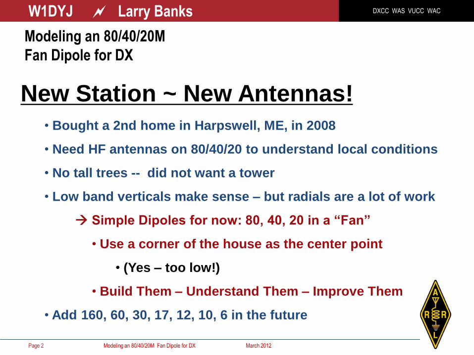
New Station ~ New Antennas!
• Bought a 2nd home in Harpswell, ME, in 2008
• Need HF antennas on 80/40/20 to understand local conditions
• No tall trees -- did not want a tower
• Low band verticals make sense – but radials are a lot of work
Simple Dipoles for now: 80, 40, 20 in a “Fan”
• Use a corner of the house as the center point
• (Yes – too low!)
• Build Them – Understand Them – Improve Them
• Add 160, 60, 30, 17, 12, 10, 6 in the future

DXCC WAS VUCC WAC W1DYJ ~ Larry Banks
Modeling an 80/40/20M Fan Dipole for DX March 2012 Page 3
Deck
Deck
80 40
20
Modeling an 80/40/20M
Fan Dipole for DX
Simple Dipoles for now: 80, 40, 20 Fan
Use a corner of the house as the center point
(The numbers on the wires
are for use with EZNEC.)

DXCC WAS VUCC WAC W1DYJ ~ Larry Banks
Modeling an 80/40/20M Fan Dipole for DX March 2012
Antenna Orientation
Page 4
South
America
170°
N
X
Y
Africa
90°
Europe
60°
Japan
335°
Modeling an 80/40/20M
Fan Dipole for DX

DXCC WAS VUCC WAC W1DYJ ~ Larry Banks
Modeling an 80/40/20M Fan Dipole for DX March 2012
Actual
Installation
Page 5
Polyphaser
Lightening
Protection
Dipole
Center
Screw Eye
for 80M
VHF / UHF
Cables
through
the wall in
Shack
Balun and
Dipole Center
DXCC WAS VUCC WAC W1DYJ ~ Larry Banks
Modeling an 80/40/20M Fan Dipole for DX March 2012
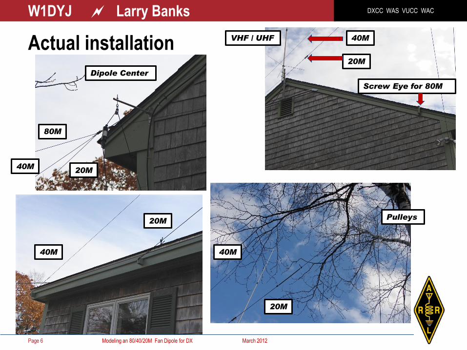
Actual installation
Page 6
Screw Eye for 80M
20M
40M
40M
20M
VHF / UHF
20M
40M
Pulleys
Dipole Center
20M 40M
80M
DXCC WAS VUCC WAC W1DYJ ~ Larry Banks
Modeling an 80/40/20M Fan Dipole for DX March 2012 Page 7
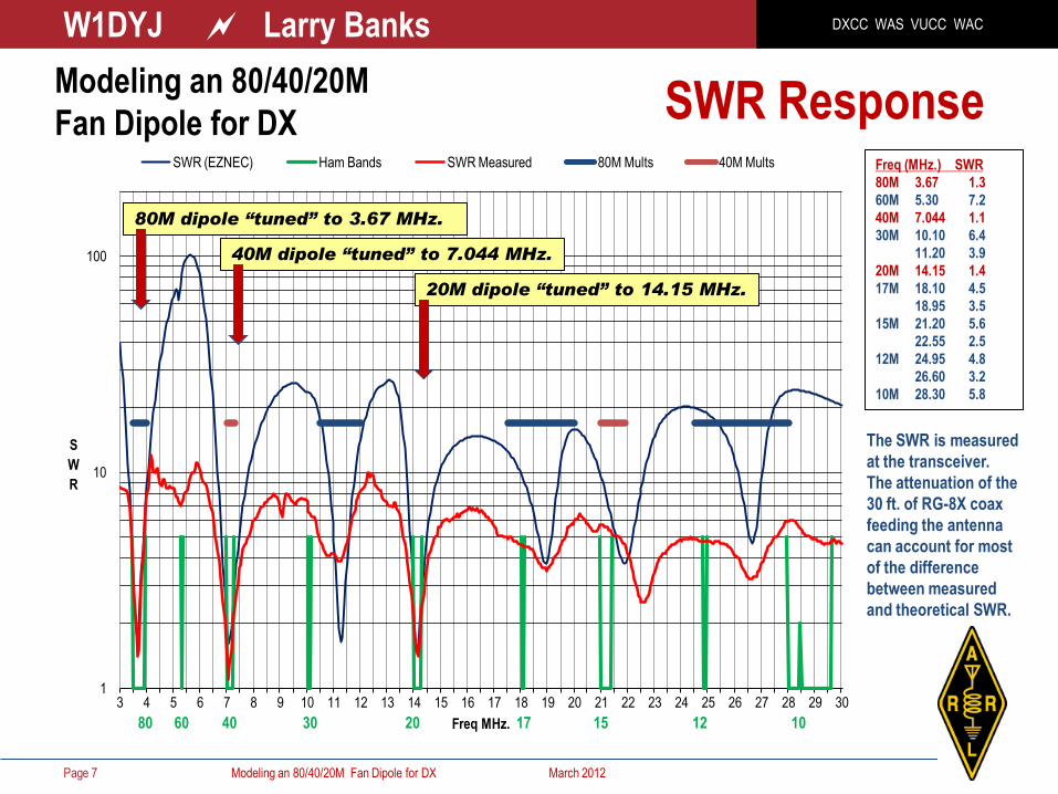
SWR Response
1
10
100
3 4 5 6 7 8 9 10 11 12 13 14 15 16 17 18 19 20 21 22 23 24 25 26 27 28 29 30
S
W
R
Freq MHz.
SWR (EZNEC) Ham Bands SWR Measured 80M Mults 40M Mults
80 60 40 30 20 17 15 12 10
Freq (MHz.) SWR
80M 3.67 1.3
60M 5.30 7.2
40M 7.044 1.1
30M 10.10 6.4
11.20 3.9
20M 14.15 1.4
17M 18.10 4.5
18.95 3.5
15M 21.20 5.6
22.55 2.5
12M 24.95 4.8
26.60 3.2
10M 28.30 5.8
80M dipole “tuned” to 3.67 MHz.
40M dipole “tuned” to 7.044 MHz.
20M dipole “tuned” to 14.15 MHz.
Modeling an 80/40/20M
Fan Dipole for DX
The SWR is measured
at the transceiver.
The attenuation of the
30 ft. of RG-8X coax
feeding the antenna
can account for most
of the difference
between measured
and theoretical SWR.

DXCC WAS VUCC WAC W1DYJ ~ Larry Banks
Modeling an 80/40/20M Fan Dipole for DX March 2012
Where is the DX? At what angle (from the horizon) does the RF arrive?
We must always remember this simple truth:
The ionosphere controls the elevation angles of the RF we see at our
location, not our antenna!
Page 8
Data from the ARRL Antenna Book , Dean Straw N6BV editor.
Information available as tables: the statistical distribution of elevation angles that
are necessary for communication via the ionosphere from one location to
another.
Also part of the software program HFTA (High Frequency Terrain Analysis)
Modeling an 80/40/20M
Fan Dipole for DX
DXCC WAS VUCC WAC W1DYJ ~ Larry Banks
Modeling an 80/40/20M Fan Dipole for DX March 2012
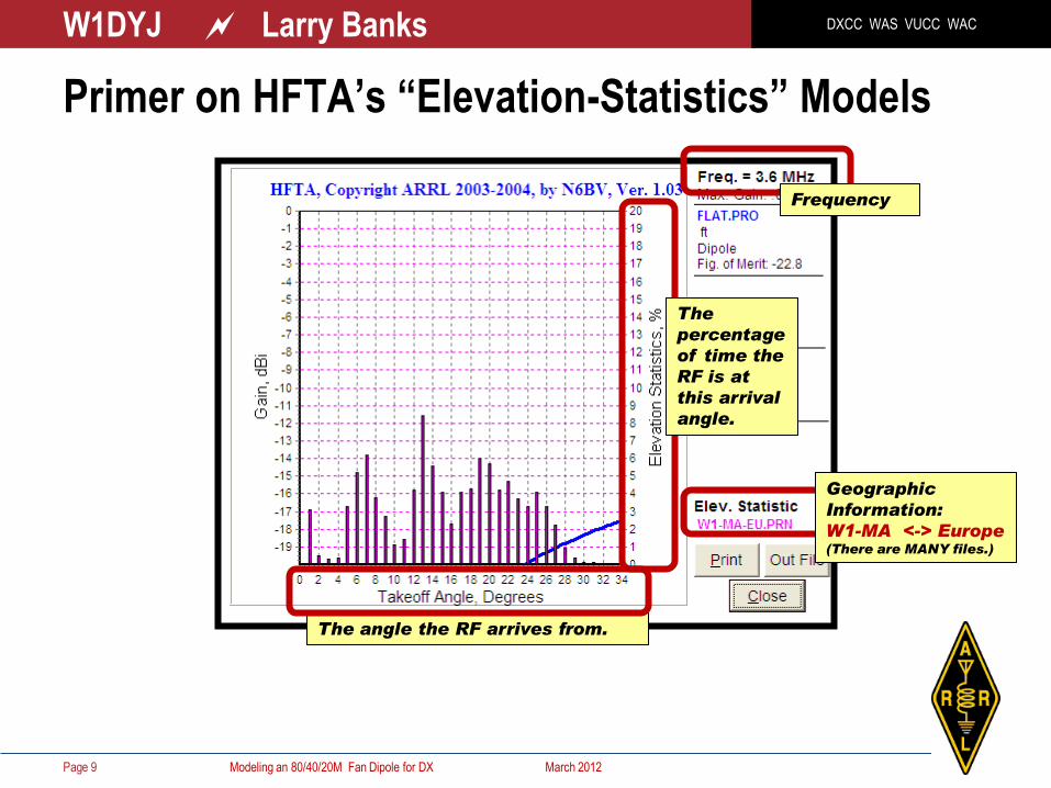
Primer on HFTA’s “Elevation-Statistics” Models
Page 9
The angle the RF arrives from.
Frequency
Geographic
Information:
W1-MA <-> Europe (There are MANY files.)
The
percentage
of time the
RF is at
this arrival
angle.

DXCC WAS VUCC WAC W1DYJ ~ Larry Banks
Modeling an 80/40/20M Fan Dipole for DX March 2012
Primer on HFTA’s “Elevation-Statistics” Models
Page 10
Example:
About 8.5% of the time,
European 80M RF arrives
at an arrival angle of 13°
Conclusion, from this one graph:
About 80% of the time, European 80M RF arrives at arrival angles between 5 22°
Note:
The statistical
data is an
overall average
of all time; i.e.
for any time,
any day, any
season, any
part of the 11-
year sunspot
cycle.
Specific
propagation
“today” will be
very limited in
angle.

DXCC WAS VUCC WAC W1DYJ ~ Larry Banks
Modeling an 80/40/20M Fan Dipole for DX March 2012
Elevation Statistics for New England – 80M
Page 11
Europe Africa
S. America Japan
5-22°
3-4°
4-11° 5-20°
3-22°
GOAL

DXCC WAS VUCC WAC W1DYJ ~ Larry Banks
Modeling an 80/40/20M Fan Dipole for DX March 2012
Elevation Statistics for New England – 40M
Page 12
Europe Africa
S. America Japan
6-16°
3-11°
5-11° 4-20°
3-20°
GOAL

DXCC WAS VUCC WAC W1DYJ ~ Larry Banks
Modeling an 80/40/20M Fan Dipole for DX March 2012
Elevation Statistics for New England – 20M
Page 13
4-18°
2-15°
3-10° 3-15°
3-18°
Europe Africa
S. America Japan
GOAL

DXCC WAS VUCC WAC W1DYJ ~ Larry Banks
Modeling an 80/40/20M Fan Dipole for DX March 2012
The previous slides show where the DX comes from, so…
How do these dipoles “play” from 3-22°
using EZNEC:
Page 14
Modeling an 80/40/20M
Fan Dipole for DX
EZNEC is a powerful but easy-to-use program for modeling and
analyzing nearly any kind of antenna in its actual operating environment.
EZNEC:
• plots azimuth and elevation patterns
• tells you gain, feedpoint impedance, SWR, and current distribution
• reports beamwidth, 3-dB pattern points, f/b ratio, takeoff angle
• …and more.

DXCC WAS VUCC WAC W1DYJ ~ Larry Banks
Modeling an 80/40/20M Fan Dipole for DX March 2012
REVIEW ~ Ideal EZNEC Dipole Patterns 3D Azimuth Elevation
Free Space
1/2 l
above real
ground
1/4 l
above real
ground

DXCC WAS VUCC WAC W1DYJ ~ Larry Banks
Modeling an 80/40/20M Fan Dipole for DX March 2012
Azimuth
Elevation Elevation
80M EZNEC patterns Data shown for 3.666 MHz.
Height = ~1/14 l
Page 16
Elevation ° Gain (dBi) @ 60°Azimuth
90 3.9 dBi r
20 - 5.6 - 9.5 dB
10 - 8.9 -12.8
5 -12.8 -16.7
Azimuth ° Gain (dBi) @ 20°Elevation
60 (Europe) -5.6 dBi
90 (Africa) -4.7 -4.9±0.9 dB
170 (S. America) -5.8
335 (Japan) -4.0
20° Europe

DXCC WAS VUCC WAC W1DYJ ~ Larry Banks
Modeling an 80/40/20M Fan Dipole for DX March 2012
Azimuth
Elevation
40M EZNEC patterns Data shown for 7.044 MHz.
Height = ~1/7 l
Page 17
Elevation ° Gain (dBi) @ 60°Azimuth
90 4.8 dBi r
20 - 1.6 - 6.4 dB
10 - 5.0 - 9.8
5 - 9.1 -13.9
Azimuth ° Gain (dBi) @ 20°Elevation
60 (Europe) -1.6 dBi
90 (Africa) -2.4 -2.1±1.6 dB
170 (S. America) -0.8
335 (Japan) -3.6
20° Europe

DXCC WAS VUCC WAC W1DYJ ~ Larry Banks
Modeling an 80/40/20M Fan Dipole for DX March 2012
Azimuth
Elevation
Page 18
20M EZNEC patterns Data shown for 14.15 MHz.
Height = ~ 0.27 l
Elevation ° Gain (dBi) @ 60°Azimuth
90 6.0 dBi r
20 1.3 - 4.7 dB
10 - 1.8 - 7.8
5 - 5.9 -11.9
Azimuth ° Gain (dBi) @ 20°Elevation
60 (Europe) 1.3 dBi
90 (Africa) 0.3 0.4±0.9 dB
170 (S. America) -0.5
335 (Japan) 0.8
20° Europe
DXCC WAS VUCC WAC W1DYJ ~ Larry Banks
Modeling an 80/40/20M Fan Dipole for DX March 2012
Conclusions
Page 19
Modeling an 80/40/20M
Fan Dipole for DX
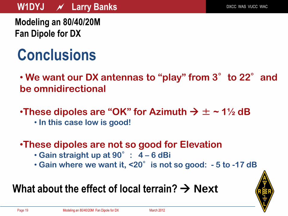
• We want our DX antennas to “play” from 3°to 22°and
be omnidirectional
•These dipoles are “OK” for Azimuth ± ~ 1½ dB • In this case low is good!
•These dipoles are not so good for Elevation • Gain straight up at 90°: 4 – 6 dBi
• Gain where we want it, <20°is not so good: - 5 to -17 dB
What about the effect of local terrain? Next
DXCC WAS VUCC WAC W1DYJ ~ Larry Banks
Modeling an 80/40/20M Fan Dipole for DX March 2012 Page 20
Modeling an 80/40/20M
Fan Dipole for DX
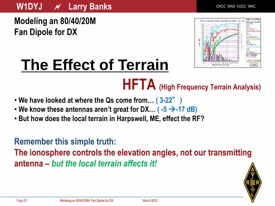
The Effect of Terrain
HFTA (High Frequency Terrain Analysis)
• We have looked at where the Qs come from… ( 3-22°)
• We know these antennas aren’t great for DX… ( -5 -17 dB)
• But how does the local terrain in Harpswell, ME, effect the RF?
Remember this simple truth:
The ionosphere controls the elevation angles, not our transmitting
antenna – but the local terrain affects it!

DXCC WAS VUCC WAC W1DYJ ~ Larry Banks
Modeling an 80/40/20M Fan Dipole for DX March 2012
HFTA
Page 21
HFTA (HF Terrain Assessment),
developed by Dean Straw N6BV. HFTA is
available on the latest ARRL Antenna Book
CD-ROM. HFTA shows visually how the
elevation angles of a horizontal dipole, Yagi
or stacked Yagis cover the statistical
distribution of elevation angles that are
necessary for communication via the
ionosphere from one location to another.
We must always remember this simple
truth:
The ionosphere controls the elevation
angles, not our transmitting antenna!
Frequency Simple Antenna
Your Local
Terrain
Statistical
Model of
QSOs
Antenna
Height

DXCC WAS VUCC WAC W1DYJ ~ Larry Banks
Modeling an 80/40/20M Fan Dipole for DX March 2012
HFTA ~ the Local Terrain to Europe
Page 22
DeLorme Topo USA 7.0 HFTA
Flat
(EZNEC)
From
“MicoDEM”
USGS
Antenna
Height

DXCC WAS VUCC WAC W1DYJ ~ Larry Banks
Modeling an 80/40/20M Fan Dipole for DX March 2012
HFTA ~ “Primer”
Page 23
From W1 Europe: % QSOs vs. Takeoff Angle
Frequency of Analysis
Terrain /
Antenna
Effect of the terrain on
this dipole @ 4º: +10 dB
+10 dB

DXCC WAS VUCC WAC W1DYJ ~ Larry Banks
Modeling an 80/40/20M Fan Dipole for DX March 2012
HFTA: Europe ~ 60°
Page 24
80M (3.666 MHz) 40M (7.044 MHz) 20M (14.15 MHz)

DXCC WAS VUCC WAC W1DYJ ~ Larry Banks
Modeling an 80/40/20M Fan Dipole for DX March 2012
HFTA: Africa ~ 90°
Page 25
80M (3.666 MHz) 40M (7.044 MHz) 20M (14.15 MHz)

DXCC WAS VUCC WAC W1DYJ ~ Larry Banks
Modeling an 80/40/20M Fan Dipole for DX March 2012
HFTA: South America ~ 170°
Page 26
80M (3.666 MHz.) 40M (7.044 MHz.) 20M (14.15 MHz.)

DXCC WAS VUCC WAC W1DYJ ~ Larry Banks
Modeling an 80/40/20M Fan Dipole for DX March 2012
HFTA: Japan ~ 336°
Page 27
80M (3.666 MHz.) 40M (7.044 MHz.) 20M (14.15 MHz.)

DXCC WAS VUCC WAC W1DYJ ~ Larry Banks
Modeling an 80/40/20M Fan Dipole for DX March 2012
Summarize: Effect of Terrain
Page 28
Modeling an 80/40/20M
Fan Dipole for DX
How can I improve on these dipoles? Next
Europe Africa S. America Japan
80M 0 ++ — +/-
40M ++ ++ +/- 0
20M + + +/- ++
The Effect of the Local Terrain

DXCC WAS VUCC WAC W1DYJ ~ Larry Banks
Modeling an 80/40/20M Fan Dipole for DX March 2012 Page 29
Will making them higher help much?
• EZNEC with dipole centers @ 36’ (rather than 18’)
• HFTA with 20M dipole center = 18’ & 36’
What about a different antenna on 20M?
• HFTA: Dipole 2 18’ vs. 2 el Yagi & 3 el Yagi @ 32’
Modeling an 80/40/20M
Fan Dipole for DX
Potential Improvements
DXCC WAS VUCC WAC W1DYJ ~ Larry Banks
Modeling an 80/40/20M Fan Dipole for DX March 2012
Potential Improvement?
Page 30
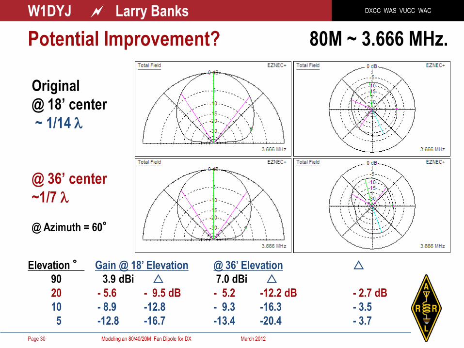
80M ~ 3.666 MHz.
Elevation ° Gain @ 18’ Elevation @ 36’ Elevation r
90 3.9 dBi r 7.0 dBi r
20 - 5.6 - 9.5 dB - 5.2 -12.2 dB - 2.7 dB
10 - 8.9 -12.8 - 9.3 -16.3 - 3.5
5 -12.8 -16.7 -13.4 -20.4 - 3.7
Original
@ 18’ center
~ 1/14 l
@ 36’ center
~1/7 l
@ Azimuth = 60°
DXCC WAS VUCC WAC W1DYJ ~ Larry Banks
Modeling an 80/40/20M Fan Dipole for DX March 2012 Page 31
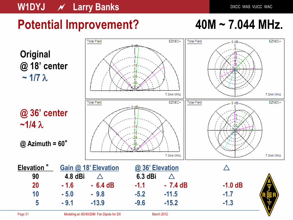
Original
@ 18’ center
~ 1/7 l
@ 36’ center
~1/4 l
@ Azimuth = 60°
Elevation ° Gain @ 18’ Elevation @ 36’ Elevation r
90 4.8 dBi r 6.3 dBi r
20 - 1.6 - 6.4 dB -1.1 - 7.4 dB -1.0 dB
10 - 5.0 - 9.8 -5.2 -11.5 -1.7
5 - 9.1 -13.9 -9.6 -15.2 -1.3
Potential Improvement? 40M ~ 7.044 MHz.

DXCC WAS VUCC WAC W1DYJ ~ Larry Banks
Modeling an 80/40/20M Fan Dipole for DX March 2012 Page 32
Original
@ 18’ center
~ 1/4 l
@ 36’ center
~1/2 l
@ Azimuth = 60°
Elevation ° Gain @ 18’ Elevation @ 36’ Elevation r
90 6.0 dBi r -0.1 dBi r
20 1.3 - 4.7 dB +4.0 +4.1 dB +8.7 dB
10 - 1.8 - 7.8 +0.8 +0.9 +8.7
5 - 5.9 -11.9 - 3.5 -3.4 +8.5
Potential Improvement? 20M ~ 14.15 MHz.

DXCC WAS VUCC WAC W1DYJ ~ Larry Banks
Modeling an 80/40/20M Fan Dipole for DX March 2012
HFTA – 20M
Dipoles @ 18’ & 36’
(To Europe)
Page 33
Potential Improvement? 20M ~ 14.15 MHz.

DXCC WAS VUCC WAC W1DYJ ~ Larry Banks
Modeling an 80/40/20M Fan Dipole for DX March 2012
HFTA – 20M
Dipole @ 18’
2 El Yagi @ 32’
3 El Yagi @ 32’
(To Europe)
Page 34
Potential Improvement? 20M ~ 14.15 MHz.
DXCC WAS VUCC WAC W1DYJ ~ Larry Banks
Modeling an 80/40/20M Fan Dipole for DX March 2012
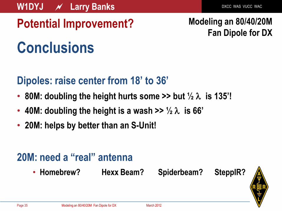
Conclusions Dipoles: raise center from 18’ to 36’
• 80M: doubling the height hurts some >> but ½ l is 135’!
• 40M: doubling the height is a wash >> ½ l is 66’
• 20M: helps by better than an S-Unit!
20M: need a “real” antenna
• Homebrew? Hexx Beam? Spiderbeam? SteppIR?
Page 35
Modeling an 80/40/20M
Fan Dipole for DX
Potential Improvement?

DXCC WAS VUCC WAC W1DYJ ~ Larry Banks
Modeling an 80/40/20M Fan Dipole for DX March 2012 Page 36
• Saltwater Analysis
• Other HF Bands
Modeling an 80/40/20M
Fan Dipole for DX
Appendix

DXCC WAS VUCC WAC W1DYJ ~ Larry Banks
Modeling an 80/40/20M Fan Dipole for DX March 2012
Salt Water Analysis
Page 37
Modeling an 80/40/20M
Fan Dipole for DX
Effect of Location – what about the cove?
Does it help low angle radiation?
Theory: Salt water affects vertical antennas more than horizontals.

DXCC WAS VUCC WAC W1DYJ ~ Larry Banks
Modeling an 80/40/20M Fan Dipole for DX March 2012
Effect of Salt Water– what about the cove? Theory: Salt water affects vertical antennas more than horizontals.
Page 38
Previous plots assumed average soil:
Conductivity = 0.005 Siemens/meter
Dielectric Constant = 13
Actual location:
Salt water ~400’ to the North West
~1000’ to the East
For Salt Water:
Conductivity = 5 Siemens/meter
Dielectric Constant = 81
Experiment:
“Average” soil for 400’ circle
Salt Water beyond that
EZNEC can have two different
“soils” in a radial pattern: 400 ft
DXCC WAS VUCC WAC W1DYJ ~ Larry Banks
Modeling an 80/40/20M Fan Dipole for DX March 2012
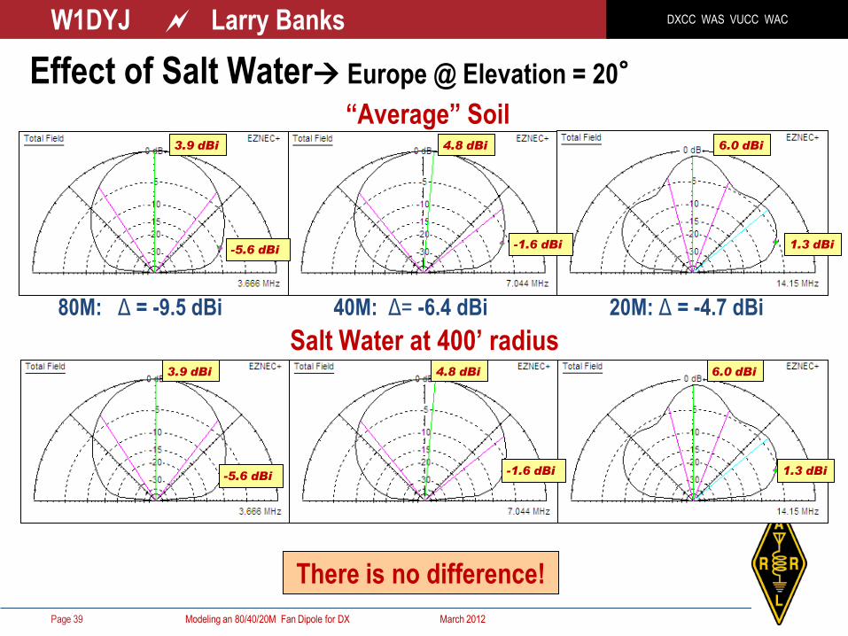
Effect of Salt Water Europe @ Elevation = 20°
Page 39
80M: Δ = -9.5 dBi 40M: Δ= -6.4 dBi 20M: Δ = -4.7 dBi
Salt Water at 400’ radius
There is no difference!
“Average” Soil 3.9 dBi
-5.6 dBi
4.8 dBi
-1.6 dBi
6.0 dBi
1.3 dBi
3.9 dBi
-5.6 dBi
4.8 dBi
-1.6 dBi
6.0 dBi
1.3 dBi

DXCC WAS VUCC WAC W1DYJ ~ Larry Banks
Modeling an 80/40/20M Fan Dipole for DX March 2012
Effect of Salt Water Europe @ Elevation = 20° A Test of the Method
Page 40
80M: Δ = -9.5 dBi 40M: Δ= -6.4 dBi 20M: Δ = -4.7 dBi
“Average” Soil 3.9 dBi
-5.6 dBi
4.8 dBi
-1.6 dBi
6.0 dBi
1.3 dBi
Salt Water everywhere (but house doesn’t float!) 8.6 dBi
-5.8 dBi
8.1 dBi
-0.0 dBi
8.1 dBi
2.8 dBi
80M: Δ = -14.4 dBi 40M: Δ= -8.1 dBi 20M: Δ = -5.3 dBi
Don’t use horizontal dipoles on a houseboat!

DXCC WAS VUCC WAC W1DYJ ~ Larry Banks
Modeling an 80/40/20M Fan Dipole for DX March 2012
Other HF Bands
Page 41
Modeling an 80/40/20M
Fan Dipole for DX

DXCC WAS VUCC WAC W1DYJ ~ Larry Banks
Modeling an 80/40/20M Fan Dipole for DX March 2012 Page 42
EZNEC patterns 60M ~ 5.3 MHz.
Height = ±0.09l
SWR ~ 7.2:1

DXCC WAS VUCC WAC W1DYJ ~ Larry Banks
Modeling an 80/40/20M Fan Dipole for DX March 2012 Page 43
EZNEC patterns 30M ~ 10.1 MHz 11.2 MHz.
Height = ±0.18l 3.9:1
SWR ~ 6.4:1

DXCC WAS VUCC WAC W1DYJ ~ Larry Banks
Modeling an 80/40/20M Fan Dipole for DX March 2012 Page 44
EZNEC patterns 17M ~ 18.1 MHz
Height = ±0.32l 18.95 MHz.
SWR ~ 4.5:1 3.5:1

DXCC WAS VUCC WAC W1DYJ ~ Larry Banks
Modeling an 80/40/20M Fan Dipole for DX March 2012 Page 45
EZNEC patterns 15M ~ 21.2 MHz
Height = ±0.37l 22.25 MHz.
SWR ~ 5.6:1 2.5:1
DXCC WAS VUCC WAC W1DYJ ~ Larry Banks
Modeling an 80/40/20M Fan Dipole for DX March 2012 Page 46
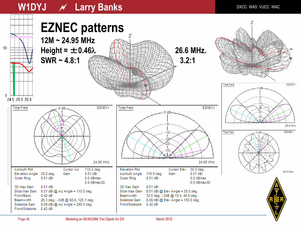
EZNEC patterns 12M ~ 24.95 MHz
Height = ±0.46l 26.6 MHz.
SWR ~ 4.8:1 3.2:1

DXCC WAS VUCC WAC W1DYJ ~ Larry Banks
Modeling an 80/40/20M Fan Dipole for DX March 2012 Page 47
EZNEC patterns 10M ~ 28.3 MHz
Height = ±0.55l
SWR ~ 5.8:1

DXCC WAS VUCC WAC W1DYJ ~ Larry Banks
Modeling an 80/40/20M Fan Dipole for DX March 2012 Page 48
Modeling an 80/40/20M
Fan Dipole for DX
Thank You
www.qsl.net/w1dyj