modeling and control of pmsm drive using mrac with signal
TRANSCRIPT

Modeling and Control of PMSM Drive UsingMRAC with Signal Adaptation Algorithm
Miroslav HorvaticUniversity of Applied Sciences
J. Krizanica b.b., 42000 Varazdin, CroatiaE-mail: [email protected]
Zeljko Ban, Toni BjazicDepartment of Control and Computer Engineering
University of ZagrebFaculty of Electrical Engineering and Computing
Unska 3, HR-10000 Zagreb, CroatiaE-mail: [email protected]
Abstract— The paper deals with modeling and control ofthe permanent magnet synchronous motor (PMSM) drive. Themathematical model of the drive with basic PI control loops isobtained from experimental data by parameter optimization.The model reference adaptive control (MRAC) algorithm withsignal adaptation is adjusted for control of the drive inpresence of the measuring noise. Algorithm parameters areobtained by computer optimization. Behavior of the controlsystem is tested by computer simulation.
I. INTRODUCTION
The permanent magnet synchronous motor (PMSM) driveis drive which significance rise in the group of low powerdrives in recent years because of the higher power density,lower moment of inertia and simplicity of the motor main-tenance [1]. The usage of vector control simplifies the speedand torque control procedures and enables wide area ofapplication of the motor [1], [2]. However, the variation inmoment of inertia of the drive causes the change in the qual-ity of the transient response, i.e. transient response speedand overshoots. In the cases where the unchanged qualityof the transient response is required with the presence ofthe moment inertia changes, the intelligent control algorithmis required. The adaptive control algorithms could be usedfor rotation speed control for PMSM drive with changeablemoment of inertia [4], [5], [7].
The adaptive control algorithms are sensible to presenceof the noise in the feedback signal. So, the filtering of themeasured signal should be considered for application of theadaptive control.
In this paper, the model reference adaptive control(MRAC) algorithm with signal adaptation is applied forcontrol of the PMSM drive with changeable moment ofinertia [4], [5], [6]. The primary control loops of the PMSMdrive are the torque vector control and PI rotation speed con-trol. The primary control loop algorithms are implementedin Servo PLC controller, which contains power supply inaddition to primary controllers. The adaptive control loopshould be designed as a outer control loop, which couldbe implemented in additional microcontroller. In order todetermine the form and parameters of the adaptive controlalgorithm, the mathematical model of the PMSM drive isrequired.
The form of the mathematical model of the PMSM driveis obtained by analytical approach [1], [2], [3], while theparameters are found by optimization procedure accordingto measured data. As the significant noise signal is presentin the measured rotation speed signal, it is necessary to
add the noise signal with the same main characteristic inthe mathematical model. The adjustable filter is designedin order to improve stability and behavior of the adaptivesystem. The main goals in the filter design were reducingthe noise impact to control and influencing to the systemtransient response as little as possible.
The MRAC with signal adaptation algorithm consist ofthe reference model and adaptation mechanism. The refer-ence model is designed as a reduced order reference modelwhich response is as close as possible to the response of thecontrolled drive with rated parameters. The parameters ofthe adaptive control algorithm are obtained by optimizationprocedure in a way to compensate the influence of themoment inertia change to system response.
The achieved results are tested by computer simulationusing Matlab/Simulink program package [8].
II. MATHEMATICAL MODEL OF THE PMSM DRIVE
The PMSM drive consists of Permanent Magnet Syn-chronous Motor and vector controlled servo converter withresolver speed feedback.
Nonlinear dynamic model of the PMSM is obtainedaccording to [1]. The stator voltage equations could bedescribed by following differential equations:
uq = Riq + Lqdiqdt
+ ωLdid + ωψr, (1)
ud = Rid + Lddiddt
− ωLqiq, (2)
whereud, uq – stator voltages in d− q coordinate system, (V),id, iq – stator currents in d− q rotor coordinate frame, (A),R – stator resistance (Ω),Ld – inductance in direct axis, (H),Lq - inductance in direction of q axis, (H),ψr – rotor magnetic flux linkage in stator, (Vs)ω – electrical rotor speed, (rad/s).
The electromagnetic torque of PMSM has a form
md =32p [ψriq + (Ld − Lq)iqid] , (3)
where p is number of motor pole pairs.Using vector control method [1] the torque and flux
control separation is provided in equations (1) to (3). Forthe rotation speed lower than rated rotation speed of thedrive, the zero direct axis current control method is used.This method determined equalizing the direct axis current

to zero in equations (1) to (3). According to this procedure,the equations (1) to (3) assumes the following form:
uq = Riq + Lqdiqdt
+ ωψr, (4)
ud = −ωLqiq, (5)
md =32pψriq. (6)
Taking into account that the rotor flux linkage ψr isconstant at constant temperature, the equations (4) to (6)assume the form of the linear differential equations. Theseequations are similar to the equations of the separatelyexcited dc motor drive with the constant flux excitation. Thecurrent iq represents the component of the stator current thatproduces the torque. The electromechanical equation of themotor could be described by the following equation:
Jdωm
dt= (md −ml −mfr) , (7)
whereJ – total moment of inertia, (kgm2)ωm – mechanical rotor speed, (rad/s),ml – is load torque, (Nm),mfr – torque produced by friction, (Nm).
Electrical rotor speed is proportional to mechanical rotorspeed:
ω = pωm. (8)
The linear model of the PMSM drive according toLaplace transform of the equations (4) to (8) is shown onFig. 1.
The primary control of PMSM drive is based on cascadecontrol with two control loops: torque control loop androtation speed control loop. The primary controllers areimplemented by digital signal processor in servo PLCsystem. The switching frequency of the inverter controlledby microcontroller is 16 kHz. As the response of the torquecontrol loop is significantly faster than the response ofthe speed control loop the torque control loop could besimplified and approximated by element with proportionalbehavior [3]. So, the torque controller together with vectorcontrol algorithms, switcher and stator circuit relevant fordetermining the torque of the motor could be described withfollowing equation:
Gt(s) =Md(s)
MdrefV (s)= Kt, (9)
whereGt(s) – transfer function of the torque control loop,Kt – torque control loop gain, (Nm/V),Md – torque of the PMSM, (Nm),
Fig. 1. Linear block diagram of the PMSM drive.
TABLE ITHE PARAMETERS OF THE PMSM DRIVE MODEL OBTAINED BY
OPTIMIZATION.
Par. Value Unit Par. Value Unit
Kt 0.073 Nm/V Kpω 5Td 1 ms Tiω 20 msKω 0.0318 Vs/rad Tω 2 msJn 7.2 · 10−5 kgm2 Mt 0.043 Nm
MdrefV – reference signal of the torque (V),s – Laplace variable.
The rotation speed is measured by resolver which signalis filtered. The transfer function of the resolver and filtercould be described with transfer function:
Gω(s) =ΩmrV (s)Ωm(s)
=Kω
1 + Tωs, (10)
whereGω – transfer function of the rotation speed sensor,Kω – gain of the rotation speed sensor, (Vs/rad),Tω – time constant of the rotation speed sensor, (s),Ωm – rotation speed of the PMSM, (rad/s),ΩmrV – measured signal of the rotation speed, (V).
The rotation speed controller is PI controller and couldbe described by transfer function:
Gc(s) =MdrefV (s)
ΩmrefV (s) − ΩmrV (s)= Kpω
(1 +
1Tiωs
),
(11)whereKpω – gain of the speed controller,Tiω – time constant of the speed controller, (s),ΩmrefV – reference signal of the rotation speed, (V).
The communication between the Servo PLC where theprimary controllers are implemented and additional con-troller for the adaptive control algorithm is realized byanalog signals. So, the A/D and D/A converters are usedfor conversion of the signals from the analog to the digitalform and from the digital to the analog form, respectively.The transfer function of the controller with built-in filter isdescribed by transfer function of the form:
GA/D(s) = GD/A(s) =1
1 + Tds(12)
where Td is time constant of the A/D and D/A converter.The controlled PMSM drive is mechanically coupled with
another PMSM drive which is used for producing loadtorque. Beside the load torque, the Coulomb friction torqueis present. The friction torque could be described by theequation of the form:
Mfr(t) = Mt sign(ωm) (13)
where Mt is constant value of the Coulomb friction torque.The block diagram of the complete PMSM drive is shown
on Fig. 2.The parameters of the PMSM drive are obtained accord-
ing to manufacturer data and by optimization procedureaccording to measured signals of the drive. Optimizationprocess is performed by Matlab/Simulink program packagewith Optimization toolbox [8], [9]. The drive parametersare shown in Table I.

Fig. 2. Block diagram of vector controlled PMSM drive system.
According to rotation speed recording, it is evident thatinfluence of the variable moment of inertia of the loadingmechanism to the PMSM drive significantly change thequality of the transient responses. So, the application ofthe adaptive control algorithm is recommended.
III. MRAC ALGORITHM WITH SIGNAL ADAPTATION
The classical approach to the MRAC system designrequires the same order of the referent model and theadjustable system as well as the measurable full state vector[10], [11]. The MRAC system with signal adaptation isstable according to the Lyapunov stability criterion if theadaptive algorithm has the following form [10], [11], [12]:
uA(t) = h · sign (ν(t)) ,
ν(t) = dT e(t),(14)
wheredT – weighting coefficient row vector,e – reference model and adjustable system state error vector,h – value of the maximal adaptation signal,ν – generalized error signal,uA - adaptation signal.
Adaptive control algorithm according to equation (14)causes oscillations in the system. The oscillations could beavoided by modified MRAC algorithm with signal adapta-tion of the form:
uA(t) = sat (ν(t), h) =
hKv · ν(t),
−h
∀Kv · ν(t) > h∀ |Kv · ν(t)| 6 h∀Kv · ν(t) < −h
,
(15)where Kν is the gain coefficient of the generalized error.
As the full state vector mostly is not observable as wellas the full order of the system is not even known, themodified adaptive control algorithm should be used. If thereference model of the reduced order and reduced orderstate variable vector is used the adaptive system could bestable for bounded range of system parameter variation [4],[5], [6]. Moreover, it is possible to compute error signal asthe difference between the reference model and adjustablesystem measured output variable. In that case, the necessaryerror vector e(t) of the reduced order should be obtained byestimation. The MRAC algorithm with signal adaptation issensitive to the noise in the measured output signal of theadjustable system. So if the significant noise is present, thefiltering of the signal should be performed. The filter shouldhave the characteristic which should satisfactory reduce thenoise and should not deteriorate the characteristic of thesignal.
A. Structure of the adaptive control algorithm
The modified MRAC algorithm with signal adaptationis designed according to equation (15). In the algorithmdesign the reduced order reference model is used. Thedesired behavior of the adjustable system in presence ofthe variation of the moment of inertia is determined by thirdorder reference model. The reference model has the form:
GRM (s) =1
am3s3 + am2s2 + am1s+ 1. (16)
The parameters of the reference model are obtained byoptimization, so that reference model describes the drive’sbehavior with nominal moment of inertia. Its parameters areshown in Table II.
The error vector determined by output variable of thePMSM drive and reference model is the first order vector.As the reduced error vector should consist of two morestate variables, the first and second derivative of the errorsignal should be obtained. Instead of using estimator thediscrete domain numerical derivative calculation method isused. The transfer functions for determining the derivativesof the error signal in the Z domain has the following form:
G1mrdV (z) = z−1Tdiscz , G2mrdV (z) = z2−2z+1
T 2discz2 , (17)
whereG1mrdV (z) – transfer function for calculation of the firstderivative,G2mrdV (z) – transfer function for calculation of the secondderivative,Tdisc – sampling time,z – Z-domain variable.
Block diagram of the whole adaptive control systembased on the modified MRAC algorithm with signal adapta-tion according to equations (15) to (17) is shown on Fig. 3.To achieve the rotation speed response overshoot lower than10%, a first order filter with time constant Tci = 9.4 ms andunity gain is added to the drive input.
The PMSM drive is modeled according to the blockdiagram on Fig. 2. The adaptive control algorithm shouldbe implemented in the microcontroller. As the PMSM drive
TABLE IITHE REFERENCE MODEL PARAMETERS.
Parameter Value
am1 0.012295am2 9.6679 · 10−5
am3 1.7343 · 10−7
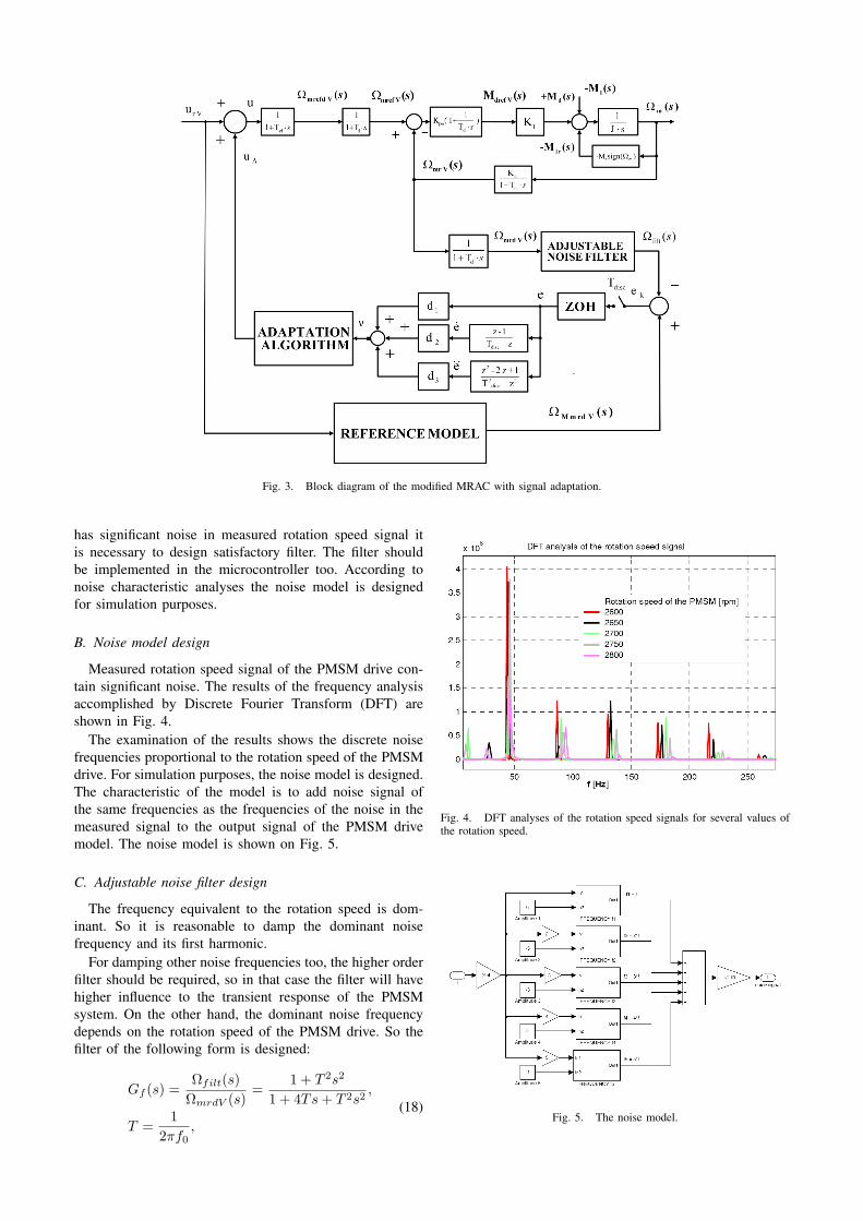
Fig. 3. Block diagram of the modified MRAC with signal adaptation.
has significant noise in measured rotation speed signal itis necessary to design satisfactory filter. The filter shouldbe implemented in the microcontroller too. According tonoise characteristic analyses the noise model is designedfor simulation purposes.
B. Noise model design
Measured rotation speed signal of the PMSM drive con-tain significant noise. The results of the frequency analysisaccomplished by Discrete Fourier Transform (DFT) areshown in Fig. 4.
The examination of the results shows the discrete noisefrequencies proportional to the rotation speed of the PMSMdrive. For simulation purposes, the noise model is designed.The characteristic of the model is to add noise signal ofthe same frequencies as the frequencies of the noise in themeasured signal to the output signal of the PMSM drivemodel. The noise model is shown on Fig. 5.
C. Adjustable noise filter design
The frequency equivalent to the rotation speed is dom-inant. So it is reasonable to damp the dominant noisefrequency and its first harmonic.
For damping other noise frequencies too, the higher orderfilter should be required, so in that case the filter will havehigher influence to the transient response of the PMSMsystem. On the other hand, the dominant noise frequencydepends on the rotation speed of the PMSM drive. So thefilter of the following form is designed:
Gf (s) =Ωfilt(s)
ΩmrdV (s)=
1 + T 2s2
1 + 4Ts+ T 2s2,
T =1
2πf0,
(18)
Fig. 4. DFT analyses of the rotation speed signals for several values ofthe rotation speed.
Fig. 5. The noise model.

whereGf (s) – transfer function of the filter,f0 – damping frequency of the filter, (Hz).
The damping frequency of the filter is function of theinput signal. The filter block should have two inputs. Thefirst input is the signal which should be filtered whilethe other input should determine the primary dumpingfrequency. The second input has to be equal to the rotationspeed of the motor. As the noise filter should be part of theadaptive controller, the reference rotation speed signal willbe used instead of the measured rotation speed signal. Themodel of the adjustable noise filter is shown on Fig. 6.
D. Optimization of the error weighting coefficientsError weighting coefficient vector d (size 3 × 1) is
determined by optimization based on integral absolute error(IAE) criterion:
I =∫
|e (t)|dt, (19)
where e is the difference between the reference modeloutput and the filtered measured speed of the PMSM drive.
Optimization is carried out on the reference step changeof 300 rpm and nominal moment of inertia. The optimiza-tion resulted in the following error weighting coefficientvector:
dT =[
12.2837 0.1571 6 · 10−4]. (20)
The simulation responses of reference model output,filtered speed, error and adaptation signal, for PMSM drivewith moments of inertia J = Jn, J = 0.5Jn, J = 0.25Jn,are shown on Fig. 7, 8 and 9, respectively.
Maximum error values for PMSM drive without adapta-tion em and with MRAC with signal adaptation algorithmem,adapt are shown in Table III.
It is seen from Table III that maximum error valuesare smaller in the case of adaptive system than in thecase of non-adaptive system. Errors have relatively largevalue bacause reference model is determined for the systemwithout noise model. Also the overall system model isof sixth order and the reference model is a third orderapproximation.
Fig. 6. The model of the adjustable noise filter.
TABLE IIIMAXIMUM ERROR VALUES FOR PMSM DRIVE WITHOUT ADAPTATION
em AND WITH MRAC WITH SIGNAL ADAPTATION ALGORITHM
em,adapt .
J em (%) em,adapt (%)
Jn 68.9 49.20.5Jn 62.8 42.7
0.25Jn 60.1 48.0
Fig. 7. The simulation responses of reference model output, filtered speed,error and adaptation signal, for PMSM drive with J = Jn.
Fig. 8. The simulation responses of reference model output, filtered speed,error and adaptation signal, for PMSM drive with J = 0.5Jn.

Fig. 9. The simulation responses of reference model output, filtered speed,error and adaptation signal, for PMSM drive with J = 0.25Jn.
IV. CONCLUSION
In this paper a mathematical model of a permanentmagnet synchronous motor drive is described. The modelparameters are determined based on the manufacturer’s dataand optimization based on experimental measurements onthe drive.
Since the measurement noise is significant in the PMSMdrive, a noise model is introduced which describes the realnoise fairly well. Thus a complete PMSM drive model isobtained. The drive has a possibility of moment of inertiachange, so the drive behavior is tested by model simula-tion using program package Matlab/Simulink for differentmoments of inertia.
Compensation of moment of inertia change is achievedby model reference adaptive control with modified signaladaptation algorithm. The algorithm is sensitive to the mea-surement noise so additional filtering of the measured signalhad to be carried through. Since the measurement noisehad two dominant frequencies in its specter, a filter withtwo stop bands for those frequencies is designed. In thatway the influence of measurement noise to the adaptationalgorithm is reduced, but not completely eliminated. It isshown that maximum error values for different moments ofinertia are reduced by 12 – 20% in relation to the PMSMdrive without adaptation.
The result achieved is good considering the noise/signalratio. The authors are planning to investigate other ways ofreducing the noise influence on the adaptation algorithm,e.g. different filtering tehniques or different choice of statespace variables.
REFERENCES
[1] R. Krishnan, Electric Motor Drives; Modeling, Analysis and Control,Prentice Hall, Inc, New Jersey, 2001.
[2] W. Leonhard, Control of Electrical Drives, Springer-Verlag, BerlinHeidelberg, 1996.
[3] J. Deur, ”Servo system with vector controlled PMSM”, Ms. Theses,Faculty of Electrical Engineering, Zagreb, 1993. (in Croatian)
[4] A. Mujanovic, P. Crnosija, Z. Ban, ”Determination of transient errorand signal adaptation algorithm coefficients in MRAS”, Proceedingsof the IEEE International Symposium on Industrial Electronics, ISIE99, Maribor, p. 631-634, 1999.
[5] P. Crnosija, Z. Ban, R. Krishnan, ”Application of Model ReferenceAdaptive Control With Signal Adaptation to PM Brushless DC MotorDrives”, Proceedings of the 2002 IEEE International Symposium onIndustrial Electronics, L’Aquila, p. 689-694, 2002.
[6] P. Crnosija, R. Krishnan, T. Bjazic, ”Performance Optimization ofPM Brushless DC Motor Drive with Reference Model and SignalAdaptation Controller” Proceedings of the EDPE 2005, Dubrovnik,p. 77, 2005.
[7] P. Crnosija, Z. Ban, ”Implementation of Modified MRAC to DrivesControl”, Proceeding of the 9th European Conference on PowerElectronics and Applications, Brussels, P.1-P.9, 2001.
[8] Matlab Help, Optimization Toolbox, version 6.5, The MathWorksInc., 2002.
[9] M. Horvatic, ”Parameter optimization of the MRAC algorithm withsignal adaptation for servo system”, Diploma theses, Faculty ofElectrical Engineering and Computing, Zagreb, 2005. (in Croatian)
[10] K. J. Astrom, Adaptive control, Addison-Wesley Publishing company,Reading, Massachusetts, 1989.
[11] H. Butler, Model reference adaptive control - from theory to practice,Prentice Hall, New York, 1992.
[12] V. Chalam, Adaptive control systems - Techniques and Applications,Marcel Dekker, Inc., New York and Basel, 1987.