modeling and stress analysis of gas turbine · pdf filemodeling and stress analysis of gas...
TRANSCRIPT
International Research Journal of Engineering and Technology (IRJET) e-ISSN: 2395 -0056
Volume: 04 Issue: 01 | Jan -2017 www.irjet.net p-ISSN: 2395-0072
© 2017, IRJET | Impact Factor value: 5.181 | ISO 9001:2008 Certified Journal | Page 1063
MODELING AND STRESS ANALYSIS OF GAS TURBINE ROTOR Rakesh K1, Kanchiraya S2
1P G student, Department of Mechanical Engineering, GEC, Hassan, Karnataka, India 2Assistant professor, Department of Mechanical Engineering, GEC, Hassan, Karnataka, India
----------------------------------------------------------------***-------------------------------------------------------------
ABSTRACT - The gas turbine is the heart of all modern aircraft. The power derived from the gas turbine provides necessary thrust required for the propulsion of the aircraft. The turbine is used for the purpose of expansion. Power developed by the turbine can be augmented by the addition of the energy in order to raise the temperature of the working fluid before expansion. The turbine rotor is the most critical component in a gas turbine engine because it operates at high temperature region and provides enough power to drive the compressor and other accessories. Three materials are used such as Aluminum 2618, Ti-6Al-4V and MAR-M-247. These three materials are currently using for the manufacture of gas turbine rotor. It is necessary to determine better fatigue life characteristics of these materials. In the present work the rotor is designed using catia software and analysed using Ansys workbench 16.2 software. Stress analysis has been carried out by the using boundary conditions and loads. The results obtained from the analysis have been used to determine the fatigue life and factor of safety by using relevant formula. It is observed from the analysis that material MAR-M-247 alloy has been found to exhibit better fatigue life characteristics.
Key words: Analysis, Gas turbine rotor, Fatigue Life, Ansys Workbench, Life estimation.
1. INTRODUCTION
The main purpose of gas turbine technology is to extract the maximum energy from the working fluid and to convert it into useful work with maximum efficiency by means of a plant having maximum reliability, minimum cost, minimum supervision and minimum starting time. The gas turbine obtains its power by utilizing the energy of burnt gases in a combustion chamber and the air which is at high temperature and pressure by expanding through the several fixed and moving blades. This gas stream is used to run the compressor which supplies the compressed air to the turbine engine as well as providing remaining energy that may be used to do other work. The turbine drives the compressor so it is coupled to the turbine shaft. After compression the working fluid is to be expanded in a gas turbine, then assuming that there were no losses in both compressor and turbine, the power developed by the turbine can be increased by increasing the working fluid volume at constant pressure or by increasing the pressure at constant volume. Either of these may be done by adding heat so that the
temperature of the working fluid is increased after
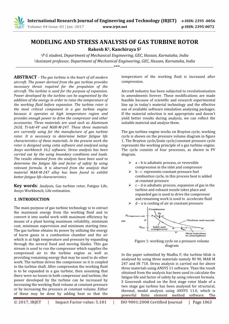
compression. Aircraft industry has been subjected to revolutionisation in amendments forever. These modifications are made feasible because of scientific and research experimental line up in today’s material technology and the effective use of available software simulation analysing packages. If the material selection is not appropriate and doesn’t yield better results during analysis, we can reflect the suitable material and analyse them. The gas turbine engine works on Brayton cycle, working cycle is shown on the pressure volume diagram in figure 1. The Brayton cycle/Joule cycle/constant pressure cycle represents the working principle of a gas turbine engine. The cycle consists of four processes, as shown in PV diagram.
a – b is adiabatic process, or reversible compression in the inlet and compressor
b - c represents constant pressure fuel combustion cycle, in this process heat is added at constant pressure
c – d is adiabatic process, expansion of gas in the turbine and exhaust nozzle takes place and expanded gas is used to drive the compressor and remaining work is used to accelerate fluid
d – a is cooling of air at constant pressure
Figure 1: working cycle on a pressure volume
diagram In the paper submitted by Madhu P, the turbine blisk is analysed by using three materials namely NI 90, MAR M 247 and IN 718. Stress analysis is carried out for above three materials using ANSYS 11 software. Then the result obtained from the analysis has been used to calculate the fatigue life and factor of safety by using relevant formula. S Gowreesh studied on the first stage rotor blade of a two stage gas turbine has been analysed for structural, thermal, modal analysis using ANSYS 11.0, which is powerful finite element method software. The

International Research Journal of Engineering and Technology (IRJET) e-ISSN: 2395 -0056
Volume: 04 Issue: 01 | Jan -2017 www.irjet.net p-ISSN: 2395-0072
© 2017, IRJET | Impact Factor value: 5.181 | ISO 9001:2008 Certified Journal | Page 1064
temperature distribution in the rotor blade has been evaluated using this software. The design features of the turbine segment of the gas turbine have been taken from the preliminary design of a power turbine for maximization of an existing turbo jet engine. It has been felt that a detail study can be carried out on the temperature effects to have a clear understanding of the combined mechanical and thermal stresses. In the paper submitted by Theju V, Uday P S, PLV Gopinath Reddy, C J Manjunath, turbine blade is designed with 2 materials they are inconel 718 and titanium T-6. An attempt is made to investigate the effect of temperature and induced stress on the turbine blades. A thermal analysis has been carried out to investigate the direction of the temperature flow which has been developed due to thermal loading. A structural analysis has been carried out to investigate the stresses shear stress and displacement of the turbine blades which has been developed due to coupling effect of thermal and centrifugal loads. They also tried to suggest the best material for a turbine blade by comparing the results obtained for 2 different materials.
2. PROCEDURE
This work involves modeling turbine rotor using catia software and carrying out detailed stress analysis of the turbine rotor. The gas turbine rotor is modeled using the modeling software catia V5 and maximum stress induced due to different loads acting on it is determined using Ansys workbench software. Before that study of different materials are carried out to select suitable material for the designing of the turbine rotor, because the turbine has to work in high working temperature without melting. By studying different material properties I come to know that aluminum, nickel and titanium possess good material properties and these three materials are good to design turbine rotor compared to other materials. So stress analysis is carried out for these 3 materials alloy. Stress analysis is carried out for aluminum 2618, nickel MAR-M-247 and titanium Ti-6Al-4V alloy.
The model is designed in catia V5 software. Then the model is imported into Ansys workbench software, the material properties are determined and then the model is meshed using the mesh tool. Later boundary conditions are applied and different loads, temperature which is acting on the turbine rotor is applied and then by solving we can obtain the various results like equivalent stress, strain and deformation value. The significant cause for the failure of gas turbine rotor is due to high temperature induced inside the gas turbine. The turbine blades have to withstand significant working temperature. Hence the material characteristics plays a very important role in determining the best suitable material for manufacturing of turbine rotor.
After stress analysis the number of cycles before failure occurs is calculated for all three materials by using strain life approach, also we can calculate the factor of safety for all the three different materials. Then by comparing the results which obtained, we have to select the best material based on the life estimated using the strain life approach.
3. RESULTS AND DISCUSSIONS The stress analysis and fatigue life for the given three materials have been carried out under maximum temperature and steady state conditions. For all the three materials under consideration the operating speed of 29000RPM has kept constant throughout the analysis.
From the above stress analysis it can be observed that the maximum working stress acts at the bolt area at the working temperature of around 910˚C and maximum von mises stress induced is within the permissible limits for all the materials which are considered for the stress analysis.
Factor of safety (FOS) is a term describing the structural capacity of a system beyond the applied loads or actual loads. A calculated ratio of strength (structural capacity) to actual applied load. This is a measure of the reliability of a particular design.
Strain life approach is used to calculate the fatigue life cycle of the above three materials and I used Muralidharan and Manson equation to calculate life of the turbine rotor and the equation is as below
(
)
( )
( )
( )
( )
Where = fatigue ductility coefficient
Ultimate stress
= obtained strain
E = Young’s modulus
Nf = Number of cycles

International Research Journal of Engineering and Technology (IRJET) e-ISSN: 2395 -0056
Volume: 04 Issue: 01 | Jan -2017 www.irjet.net p-ISSN: 2395-0072
© 2017, IRJET | Impact Factor value: 5.181 | ISO 9001:2008 Certified Journal | Page 1065
Figure 2: von-mises stress of aluminum 2618 alloy
Figure 3: Strain distribution of aluminum 2618 alloy
Figure 4: Von-mises stress distribution of MAR-M-247 alloy
Figure 5: strain distribution of MAR-M-247 alloy
Figure 6: Von-mises stress distribution of Ti-6Al-4V alloy
Figure 7: Strain distribution of Ti-6Al-4V alloy

International Research Journal of Engineering and Technology (IRJET) e-ISSN: 2395 -0056
Volume: 04 Issue: 01 | Jan -2017 www.irjet.net p-ISSN: 2395-0072
© 2017, IRJET | Impact Factor value: 5.181 | ISO 9001:2008 Certified Journal | Page 1066
The ANSYS 16.2 software is used for stress analysis of the turbine rotor and the result is a mention below For Aluminum 2618 alloy From figure 2 the maximum von mises stress induced in the turbine rotor is found to be 304.31 MPa and it act at the bolt area of the disc for the operational speed of 29000 rpm. From figure 3 it can be seen that maximum strain induced is equal to 0.0056134.
(
)
( )
( ) (
)
( )
Nickel MAR-M-247 alloy From figure 4 the maximum von mises stress induced in the turbine rotor is found to be 696.74 MPa and it act at the bolt area of the disc for the operational speed of 29000 rpm. From figure 5 it can be seen that maximum strain induced is equal to 0.0039228.
(
)
( )
( ) (
)
( )
Titanium Ti-6Al-4V alloy From figure 6 the maximum von mises stress induced in the turbine rotor is found to be 956.58 MPa and it act at the bolt area of the disc for the operational speed of 29000 rpm. From figure 7 it can be seen that maximum strain induced is equal to 0.0062834.
(
)
( )
( ) (
)
( )
The results which is obtained from the stress analysis using Ansys 16.2 is tabulated as show in the below table and also fatigue life of the turbine rotor which is calculated using strain life approach is also tabulated in the below table.
Table 1: Results of three materials Materials Aluminum
2618 Titanium Ti-6Al-4V
Nickel MAR-M-
247 Maximum
stress in MPa 304.31 956.58 696.74
Maximum strain
0.0056134 0.0062834 0.0039218
Deformation 0.29443 0.32958 0.20135 Yield strength
in MPa 370 1100 815
Ultimate tensile
strength in MPa
440 900 1036
Factor of safety
1.216 1.15 1.1697
Fatigue life cycles
2.98e5 3.023e4 6.7e5
4. CONCLUSION
The main aim of the project has been to select the best material which has better fatigue life among the three materials that is aluminum 2618 alloy, titanium Ti-6Al-4V alloy and nickel MAR-M-247 alloy considered for the future production of turbine rotor. To achieve this, a turbine rotor model has been created and stress analysis is carried out using Ansys 16.2 software.
The following conclusion has been made from the obtained results
For the given speed, temperature and geometry, the stresses induced in the component are within the permissible limits for all the three
materials so design is safe for all the materials. The maximum von mises stress in all the
materials is less than the yield strength which suggests that design is safe for all three materials.
The maximum stress induced is high in Ti-6Al-4V alloy, low in Aluminum 2618 alloy and moderate in MAR-M-247 alloy.
The number of fatigue cycle is high in MAR-M-247 alloy, so this is the best material for designing of turbine rotor among three materials.

International Research Journal of Engineering and Technology (IRJET) e-ISSN: 2395 -0056
Volume: 04 Issue: 01 | Jan -2017 www.irjet.net p-ISSN: 2395-0072
© 2017, IRJET | Impact Factor value: 5.181 | ISO 9001:2008 Certified Journal | Page 1067
REFERENCES
[1] Theju V, Uday P S, PLV Gopinath Reddy, C J Manjunath, “Design and analysis of gas turbine blade”, International journal of innovative research in science, engineering and technology, Vol. 3, issue 6, june 2014.
[2] Amr M S El-Hefny, Mustafa Arafa, A R Ragab and S M El-Raghy, “Stress analysis of a gas turbine rotor using finite element modeling”, production engineering and design for development.
[3] Madhu P, “Stress analysis and life estimation of gas turbine blisk for different materials of a jet engine”, International journal of science and research(IJSR), volume 5, issue 6, june 2016.
[4] P V Krishnakanth, G Narasa Raju, R D V Prasad, R Saisrinu, “Structural and thermal analysis of gas turbine blade using FEM”, International journal of scientific research engineering and technology(IJSRET).
[5] John V, T Ramakrishna, “Design and analysis of gas turbine blade”, International journal of advanced engineering research and studies Vol- 2, No.1, Dec 2012.
[6] S.Gowreesh, N.Sreenivasalu Reddy and N.V.Yogananda Murthy. “CONVECTIVE HEAT TRANSFER ANALYSIS OF a AERO GAS TURBINE BLADE USING ANSYS”, International journal of Mechanics of solids, vol-4, No.1, March 2009(ppt55-62).
[7] S.S.Rao, “The Finite Element method in Engineering”, BH Publications New Delhi, 3rd Edition, 1999. [8] Jet engine Rolls Royce book, 5th edition, technical publications department rolls Royce, derby, England.
[9] Robert L. Norton, Machine design An integrated approach (second edition), Pearson education.
[10] William D. Callister, Jr, Material science and Engineering, An introduction 3rd edition.
[11] William F. smith, Foundations of material science and engineering, second edition, McGraw-Hill international edition.
[12] George F. Titterton, Aircraft materials and processes, 5th edition.
[13] Lawrence W. Fisher, Selection of engineering materials and adhesives.
[14] Aerospace structural metals handbook published by CINDAS/USAF CRDA handbooks operation, Purdue University, Vol-3, Vol-4, Vol-5.
[15] Dr. K Lingaiah Machine design data handbook, vol-1 and vol-2.
[16] H Kimura and O Izumi, Titanium science and technology, proceeding of the 4th international conference on titanium.
[17] T L Anderson, Fracture mechanics, Fundamentals and applications, 2nd edition.
BIOGRAPHY RAKESH K studying M.Tech in Computational Analysis in Mechanical Sciences from Visvesvaraya Technological University, Belagavi