modeling concepts and overview of the unified modeling language (uml)
TRANSCRIPT
Modeling Concepts and Overview of the Unified Modeling Language (UML)

Modeling Introduction
• What is a model?
- Model is a representation or simplification of reality
- Abstraction allows us to focus on the essential aspects of a model
- A good model is the crux of good software development
• Why model?
- A good model helps us to visualize, specify, construct, and document what we are building
- Models helps us to view (and understand) the system under development from different perspectives
- Models obtained through abstraction enable us to handle complexity in a disciplined manner

Modeling Introduction contd.....
- Models facilitate communication between the users, the developers, and other shareholders
• Principles of Modeling
- Choose the right model
- Use different levels of abstraction
- Models should be a reflection of reality
- Different models, each representing different aspects (e.g., static vs dynamic features), are required to represent reality adequately
UML Overview
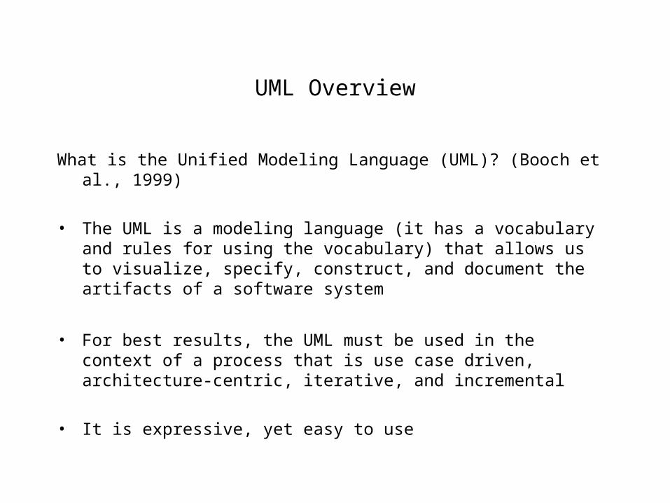
What is the Unified Modeling Language (UML)? (Booch et al., 1999)
• The UML is a modeling language (it has a vocabulary and rules for using the vocabulary) that allows us to visualize, specify, construct, and document the artifacts of a software system
• For best results, the UML must be used in the context of a process that is use case driven, architecture-centric, iterative, and incremental
• It is expressive, yet easy to use

Conceptual Model of the UML
Conceptually, the UML consists of:
• Building Blocks ( things, relationships, and diagrams)
• Rules
• Mechanisms

Things in the UML
• Structural Things (interfaces, classes, use cases, collaborations, active classes, component, node)
• Behavioral Things (interactions and state machines)
• Grouping Things (packages)
• Annotational Things (notes)

Relationships in the UML
• Association
• Generalization
• Realization
• Dependency

Diagrams in the UML
• Use Case Diagram
• Activity Diagram
• Class Diagram
• Object Diagram
• Sequence Diagram
• Collaboration Diagram
• Statechart Diagram
• Component Diagram
• Deployment Diagram

UML Rules
• A good (well-formed) model should conform to UML’s semantic rules
• Semantic rules exist for names, scope, visibility, integrity, execution
• Circumstances (such as the increasing complexity of a system under development) sometimes compel us to elide (hide details to simplify the view), leave out elements (incomplete model), or compromise the integrity of the model (inconsistent model)

Common Mechanisms in the UML
• Specifications
• Adornments
• Common division ( class/object, interface/implementation)
• Extensibility Mechanisms (Stereotypes, Tagged Values, Constraints)

Architecture
• System should be viewed from a number of perspectives
• Architecture deals with structural and behavioral aspects of a system, as well as with other concerns such as reuse, performance, scalability, functionality, constraints, trade-offs, and so forth
• Five interlocking views may be used to delineate an architecture:
Use Case View
Design View (sometimes referred to as the Logical View)
Process View
Implementation View
Deployment View

The Process
• The UML should be used in the context of a process
• For best results, the process should be:
Use Case Driven
Architecture-Centric
Iterative and incremental
• Typical phases of a process are:
Inception - make a business case
Elaboration - product vision & architecture, requirements, project plan, risk evaluation, basis for testing
Construction - iteratively and incrementally build a product, test, refine designs, ensure consistency with requirements, acceptance criteria, etc.,
Transition - hand over the system to the end users, continually evaluate, improve, and enhance the system

OO Concepts

OO Concepts
• A class encapsulates data and procedures
• A class is an abstraction that maps onto a real world abstraction
• A class may be abstract or concrete

Example of a class
public class Account {
private String accountNumber;
private float balance;
public Account(String aNumber)
{
accountNumber = aNumber;
}
public void withdraw(float money) { ...... }
public void deposit(float money) {.....}
}

Object
• An object is an instance of a class
• It can be identified with some occurrence in the real world
• Objects have identity, state, and behavior
• Example:
Account myAccount = new Account(“1000”);
myAccount is an object

Instance Versus Class Variables
• Instance variable: Each instance has its own value for that variable, e.g., each account instance has its own balance
• Class variable: It is a variable that is shared by all instances of the class, e.g., A minimum balance for an Account may be shared by all Account instances

Inheritance
• The properties of a superclass are acquired by the subclasses
• The subclasses may override and/or extend the properties of the superclass
• Example: In our example, Savings and Checking could be subclasses of Account

Polymorphism and Dynamic Binding
• A client that deals with a class can also use the subclasses of that class
• A polymorphic variable can refer to objects of different classes. Example:
Account c = new Checking(); // c.withdraw(200.00);
c = new Savings(); // c.withdraw(500.00);
• A polymorphic function may take arguments of different types. Example:
void f(Account anAccount) { .... } can be invoked with c as an argument as long c is an instance of Savings or Checking

Dynamic Binding
• Binding that occurs at compile time is called Static Binding
• Run time binding is referred to as Dynamic Binding
• Dynamic binding gives run time flexibility

Introduction to OO Analysis and Design

OO Analysis
OO Analysis:•Functional Requirements definition of the system•Description of classes in the problem domain•High-level system components and their interactions•Interaction between classes

Source: The internet

OO Design
•Transform analysis model into a feasible design•Define operations and other features•Define how these features are to be realized•Define organization of system in terms of building blocks

Why OO?
•Flexibility - reuse, extensibility•OO development is a relatively seamless process•Abstractions/classes can be mapped onto real-world concepts•OO makes it easier to deal with complexity•Lends itself to prototyping

Different Views of a System
•Functional ViewUse cases provide a static functional view while activity diagrams give a dynamic functional view
•Static Structural ViewClass and object diagrams

•Behavioral (Dynamic Structural) ViewInteraction DiagramsState Machines
•Architectural ViewLogical (e.g., Package Diagrams), hardware (e.g., Deployment Diagrams), process, and implementation (e.g., Component Diagram) architectures

What constitutes a flexible design?
•High CohesionClasses should represent a single abstraction and each method should fulfill a responsibility•Low CouplingDependencies/interactions between classes should be minimized•Behavior should be evenly distributed“Inquisitive’ control objects should be avoided•High modularity

System Functional Models
•Functional model leads to design which in turn leads to implementation
•Functional requirements define the requirements of a system from an external perspective

Types of Requirements
• Functional - system does what is it supposed to do
• Performance, e.g., response time
• Robustness, e.g., exception handling
• Compatibility with other systems, reusability, etc.,

Use Cases
•Use cases represent the typical interactions between users and the system•A use case is a coherent unit of functionality that satisfies some user-visible function, thus helping the user achieve a discrete goal•Use cases could be trivial or non-trivial, big or small

Use Case Identification
•Identify the actors•Determine the interactions between the actors and the system•What interactions are initiated by the actors?•What interactions are initiated by the system?

Use Case Identification
• What information should the system store? How is this information created, stored, updated, deleted, and queried?
• Are there any time-based activities performed by the system?
• Are there any external events that affect the system?
• Are there any activities performed when the internal state of the system changes?
Actors
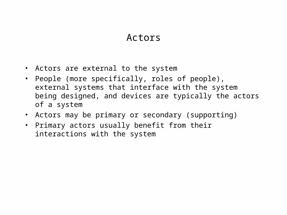
• Actors are external to the system
• People (more specifically, roles of people), external systems that interface with the system being designed, and devices are typically the actors of a system
• Actors may be primary or secondary (supporting)
• Primary actors usually benefit from their interactions with the system

PLACE ORDER
CANCEL ORDER
CANCEL ORDERITEM
RETURN ORDERITEM
CATALOG ORDER SYSTEM
CATALOG CUSTOMER
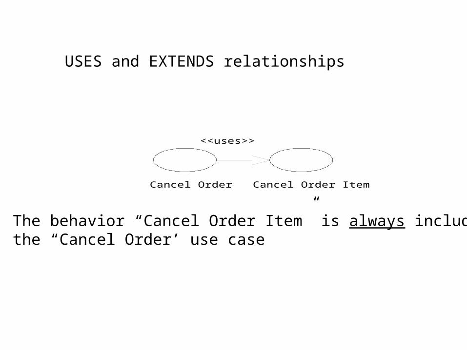
USES and EXTENDS relationships
Cancel Order
<<uses>>
Cancel Order Item
The behavior “Cancel Order Item” is always included inthe “Cancel Order’ use case

<<extends>> Relationship
Place Order Add Customer
<<extends>>
The use case “Place Order’ sometimes includes the behaviorof “Add Customer” (for example when “Place Order” attemptsto create an order for a customer who has not yet been added tothe system)
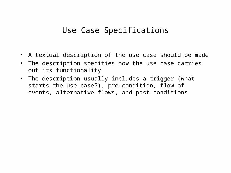
Use Case Specifications
• A textual description of the use case should be made
• The description specifies how the use case carries out its functionality
• The description usually includes a trigger (what starts the use case?), pre-condition, flow of events, alternative flows, and post-conditions

Sample Use case Specification
Name: Cancel Order Item
Trigger: The use case starts when the telephone agent (for the customer) enters “Cancel Order Item”
Pre-condition: An order o exists for the given order number
Main flow of events:
1. Find all line items for the order o
2. For each line item found
cancel line item
end

Use case description continued...
3. Order is marked canceled and the use case ends
Alternative paths
If any of the line items is “Not pending”, the order cannot be canceled, and the use case ends
Post-condition: The order has been marked canceled and saved

Activity Diagrams
•Use case presents a static view of system functionality•The sequence of use case execution, conditions under which an extension occurs, and temporal relationships are hard to divine from use case diagrams•An activity diagram flowcharts the workflow of activities and presents the steps in a use case•An activity diagram is therefore a dynamic representation os system functionality

An activity in an activity diagram may be a task, another use case, or just a step being done in the use case
An activity
A BActivity B follows A
Start End

Activity Diagram notations
A B
C
[x == 5]
[x != 5]
You could also have nested decision points

Activity Diagrams notations
A
B
C
D
Synchronization Bar

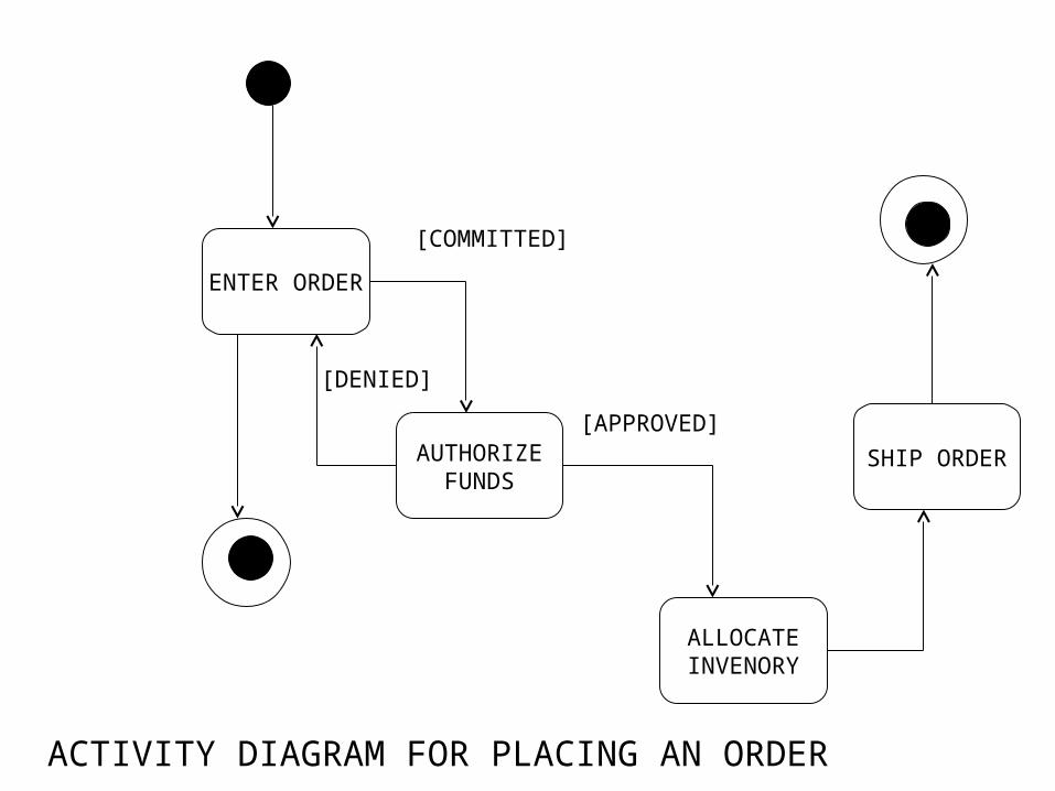
ENTER ORDER
AUTHORIZEFUNDS
ALLOCATEINVENORY
SHIP ORDER
[DENIED]
[COMMITTED]
[APPROVED]
ACTIVITY DIAGRAM FOR PLACING AN ORDER


Class Diagramming Notation

Class Diagrams
ASSOCIATION: relationships between instances of a classes, e.g., customer places order, employee works for company
•Each association has two roles•Each role has multiplicity
Customer Order
0..*1..1 0..*1..1
Role A
Role B

A B1
Only one B is associated with an A
A B1..*
One or more instances of B are associated with an A
A B
0 or 1 instance of B is associated with an A
0..1
A B*
An A is associated with 0 or more instances of B

A B1..3
1, 2, or 3 instances of B are associated with an A
0..*1..1
Customer Order
0..*1..1
Role A
Role B
The arrow head on the association implies navigability. In this example, we can determine the customer from the order
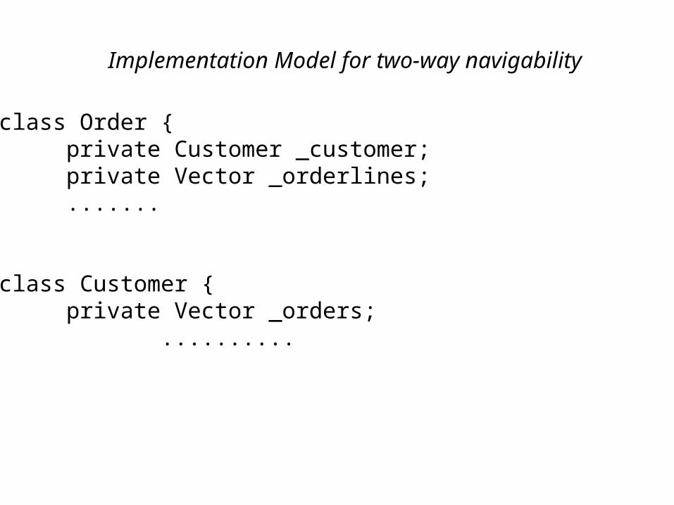
Implementation Model for two-way navigability
class Order {private Customer _customer;private Vector _orderlines;.......
class Customer {private Vector _orders;
..........

Interfaces and Abstract Classes
•An interface contains abstract methods and its member variables are static and final. It is primarily a collection of method signatures•An abstract class can have method implementations as well as variables that are not static and final
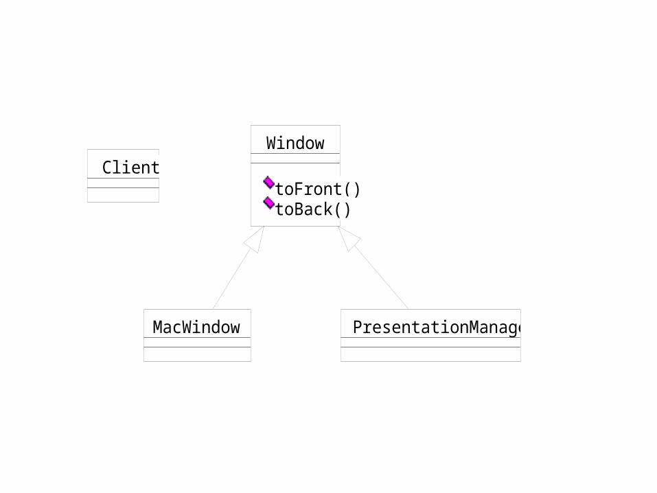
ClientWindow
toFront()toBack()
MacWindow PresentationManager
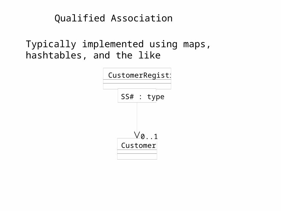
Qualified Association
Typically implemented using maps, hashtables, and the like
CustomerRegistry
Customer0..1
SS# : typeSS# : type
0..1

SPECIFICATION PERSPECTIVE ........
class Order {public OrderLine lineItem(Product aProduct);public void addLineItem(Number amount, Product
forProduct);
IMPLEMENTATION PERSPECTIVE:
class Order {private Dictionary _lineItems;

Association Class
PERSON COMPANY
Employmentperiod: dateRange
0..1
* employer
ASSOCIATION CLASS

TSet
insert(T)remove(T)
EmployeeSet
TEMPLATE CLASS
<<bind>>
<Employee>

IMPLEMENTATION.....
class Set <T> {void insert (T newElement);void remove (T anElement);........
Declare.....
Set<Employee> employeeSet;

Value Versus Reference Semantics
•Identity•Sharing•Cardinality•Direction of navigation
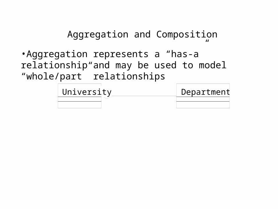
Aggregation and Composition
•Aggregation represents a “has-a” relationship and may be used to model “whole/part” relationships
DepartmentUniversity

Aggregation Versus Composition
• In aggregation, there is no link between the lifetimes of the whole and its parts
• An aggregation is semantically stronger than an association
• A part in an aggregation can be shared by other wholes
• Meaning of navigation is the same as in an association

Composition
• Semantically stronger than an aggregation
• Characterized by coincident lifetimes of the whole and its parts
• Object can be a part of only one whole
FrameWindow
Composition example from Booch et al., (1999)

Reflexive Association
Employee
0..10..*
supervises
supervisor
subordinate
0..10..*

Ternary Associations
Passenger FlightSeatAssignment
Seat
Note: Multiplicity is not shown

Attribute Syntax
• The syntax of an attribute in the UML is:
[visibility] name [multiplicity] [ :type ] [= initial value]
[{property string}]
Visibility: +, - , or # (public, private, protected)
multiplicity: refers to the number of the instances of the attribute in the class
type: data type

Property String
• changeable (default): value can be modified
• addOnly: values can be added, but not removed or changed
• frozen: value cannot be changed after object initialization

Syntax for Operations
• The UML has the following syntax for an operation:
[visibility] name [ (list of parameters) ] [: return type ]
[ {poperty string} ]
Syntax for each parameter is:
[direction] name :type [=default value]
direction may be in, out, or inout

Property Strings for operations
• isQuery
• sequential
• concurrent
• guarded
Inheritance
•Generalization versus Specialization•Visibility is determined by access directives•Public fields are not good, protected is somewhat better, and private is perhaps the best

Type Promotion (upcasting)
VehiclevehicleID
run()
Automobile
race()
class X { public static void f(Vehicle v) { v.run();}} // Safe type promotion
class X { public static void f(Vehicle v) { v.race();}} // will not work! why? what is the solution?

class Y {public static void g(Vehicle v) {Automobile a = (Automobile) v;a.race();
}}
What will this piece of code do if we pass an instance of a Truck?
class Y {public static void g(Vehicle v) {
if (v instanceOf Automobile) {Automobile a = (Automobile) v;a.race();}
}}

Polymorphism and Dynamic Binding
Device
poll()
D1 D2 D3
Client

Advantages of Polymorphism
• Client knows only about the superclass
• Changes to the subclasses do not affect the client as long as the interface is unaltered
• In some languages, recompilation may not be necessary if there are changes to the subclass that do not affect the interface presented to the client
• Pluggability
Class Specialization
•A subclass may specialize its superclass either through extension (Java, C++) or by restriction (C++)•Extension happens when:
1) You add a new behavior2) You override an existing behavior3) You add state information (value or reference)

Dependency
• Dependency may be used to model:
1) A refinement of a design feature (remember <<trace>>?)
2) Instantiation of a template
3) A refinement of an association
• A dependency is used to show a “using” relationship• Examples include bind, derive, instantiate, friend, instanceOf, refine, access,
import, become, etc.,

Notes
• Notes are often attached to elements on a diagram
An example of a note

Extension Mechanisms
• Extension mechanisms are provided to accommodate differences among OO languages
• Annotation mechanisms include specifications and adornments
• Extension mechanisms permit the designer tointroduce new properties, constraints, stereotypes, and the like

Extension mechanisms
• Specifications are often descriptions that appear in a document that is not part of the UML diagram, but may be hyperlinked to one
• A graphical representation of text is called an adornment, e.g., + stands for public
• Properties are expressed as tag-value pairs, e.g., { Date created = 12/11/00 }
• The tag or value may be implied at times

Constraints
• Constraints are rules that cannot be violated
BookCopyRental
VideoCopy
{or}

Stereotypes
• Stereotypes appear in guillements (e.g., <<actor>>)
• Stereotypes may be used with any UML construct - with specialization relationships, dependency relationships, refinements, plain associations, etc.,

Class Diagram for Order Processing
<<actor>>Telephone Agent
OrderRegistry
CustomerCatalog
name,phone#
order#
ProductCatalog
ItemNumber
Customer
Order
Line ItemCatalogItem
* 1*
1
1
*
1..*
1
1
0..1

Developing Class Diagrams

Identifying Classes
• There are three basic approaches to developing class diagrams:
1) Identification of noun phrases
2) Abstraction
3) From use cases

Class Diagrams from noun phrases
• Underline or list all the nouns from a written description of a system
• In particular, look for physical objects, roles, events, interactions, and concepts
• Refine the list by checking for redundancy, relevance, clarity (lack of vagueness), and by eliminating those nouns that stand for attributes, operations, roles, and implementation constructs

Examples from the Library System
• System and member are redundant
• you, code, and library card (?) are irrelevant
• item number, membership number, author (assuming just name), book/video status are all atributes
• checkout duties is an operation
• borrower, borrowed item indicate possible roles

From abstraction
• Use your knowledge of the domain/expertise to identify classes and their relationships
• Some modeling guidelines ....
1) Identify “kind of” and “part of’ relationships
2) Identify system interactions
3) Identify devices that interact with the system
4) Determine what information the system has to store, e.g., events, things, interactions, etc.,
5) Identify roles

Stock Trading Example
• Some of the classes that we can abstract from the Stock Trading example are:
Tangible things: Account, Stock, Order
Roles: customer, service representative
Events: security transfer
Interactions: Match (buy and sell orders)

Classes from use cases
• The identification of classes and the resulting class diagram is use-case driven
• Identify use cases and then step through each scenario of the use case, each time ensuring that the class diagram supports the use case
• This is not always straight forward and is perhaps best when used in conjunction with noun identification and abstraction

Pros and Cons
• Advantages of noun identification:
1) A mechanical approach that appeals to novices
2) Domain knowledge is not required
3) Stopping rule is clear
• Disadvantages:
1) Tedious
2) Assumes that a written specification is available
3) The quality of the class diagram is dependent on the fidelity of the specification

Advantages and disadvantages of abstraction
• Efficient
• Uses domain expertise
• Drawbacks are:
1) Extensive knowledge required
2) Poor traceability from design & implementation constructs to requirements
3) Easy to get bogged down
4) Stopping rule is not clear

Pros and cons of using use cases for class identification
• Resulting model is likely to be consistent with behaviors
• Good for understanding, explaining, and validating requirements - provides good traceability from design & implementation back to requirements
• Disadvantages:
1) There could be hundreds of use cases
2) A good knowledge and understanding of the domain is required to write use cases
3) Scoping is a problem
4) Not straightforward

A practical approach
• Use a combination of the three approaches
• The order in which the approaches are used is not important
• Validation is important
• Whenever possible, use a domain expert to guide you

Drawing flexible Class Diagrams

Cohesion
• The more diverse a class the less cohesive it is
• A class should map on to a single concept or abstraction
• High cohesion is desirable
• High cohesion may be achieved by:
1) Having classes that represent just one abstraction and
2) Having methods that do one and only one function

Problems with less cohesive classes
• Difficult to understand
• Assumes that two or more abstractions embodied in a class are always in a 1:1 relationship
• May lead to a messy inheritance structure

Account class representing two abstractions
Account
LoanAccount CashAccount IndividualAccount CorporateAccount

Cohesive Classes
1..*0..*
LoanAccount CashAccount IndividualAccount CorporateAccount
Account Customerholder
1..*0..*

Increasing Cohesion
• Follow the rules of normalization:
Have single-valued attributes
A class should contain attributes that really belong to it

Coupling
• Coupling is a measure of how much dependency exists between the classes/objects in a system
• A class that is highly (tightly) coupled knows too much about the world around it

Types of Coupling
• Identity coupling - an object holds a reference to another object. Minimize navigability to reduce this coupling
• Representational Coupling - an object refers to another either by accessing its public data or by invoking its accessor method(s)
• Subclass coupling - occurs when a client holds a reference to a specific class (such as a subclass) rather than to something more abstract
• Inheritance Coupling - Coupling that results from an inheritance structure

Subclass Coupling
VideoCopy
Rental
BookCopy

Reducing Subclass Coupling
VideoCopy
BookCopy
Rental LendableCopy
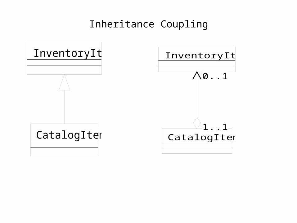
Inheritance Coupling
CatalogItem
InventoryItem InventoryItem
CatalogItem1..1
0..1
1..1
0..1

Inheritance versus Composition/Delegation
• Use inheritance when:
1) There is a “kind of” relationship rather than a “role of”
2) No transmutation of subclass objects occurs
3) The inheriting classes extend rather than override or nullify superclass methods
4) “kind of” relationships exist among classes in the problem domain (e.g., kind of roles, transactions, etc.,)

Subclassing a Utility Class
• Subclassing a Utility class (e.g., Vector) is not desirable because:
1) We have no control over changes made to Utility classes
2) It weakens encapsulation

Class Generalization
• Use superclasses when:
1) Two or more classes have common implementation
2) Two or more classes share a common interface

Class Specialization
• Subclasses can specialize their superclass by:
1) Adding attributes
2) Adding associations, i.e., references
3) Adding new behavior
4) Overriding the method of their superclass

Distinctions based on state
Employee
Manager NonManager
Employee<<abstract>>
Manager
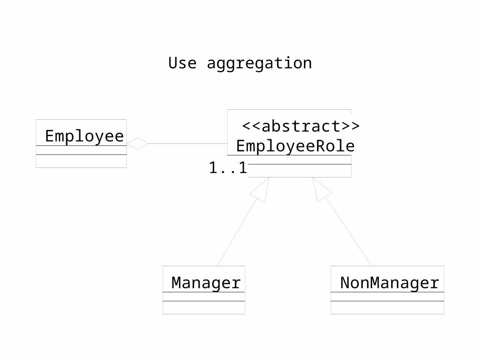
Use aggregation
1..1
Manager NonManager
EmployeeRole<<abstract>>
Employee
1..1

Aggregation versus Specialization
• Aggregation is better when:
1) Class has different aspects to be specialized
2) Properties are not shared by all subclasses
3) Multiple Inheritance is used

Placing properties in the right class
• A superclass property should apply to all its subclasses
• A shared property should be implemented just once

How do we handle this?
f() has identical implementations in B1 and B2
A
B1
f()
B2
f()
B3

Multiple Inheritance versus Aggregation
• Don’t use Multiple Inheritance when there is no “is-a-kind-of” relationship
• An ATM aggregates CardReader, Keyboard, DisplayScreen, and CashDrawer
• Parts should be hidden inside the aggregate
• Interactions between parts should be through the whole

Reusing parts of an aggregate
1..1
TollBooth
cardInserted()
ATM
cardInserted()
CardReaderCardDriven
cardInserted()
<<interface>>
1..1

Dynamic Diagramming Notation

Static and Dynamic Views
Modeling Activity Static View Dynamic ViewRequirements Analysis Use cases Activity DiagramsDesign Class & Object diagrams Interaction Diagrams and
Statecharts (State-Transition Diagrams)

• A scenario is an instance of a use case, i.e., it is one pass through the use case
• Use cases are described using:
1) A textual description
2) Activity diagrams

Textual Description
• Start with a general description
• Factor if necessary
• Provide details of steps - main flows, alternative flows including exceptions

Interaction Diagrams
• Interaction diagrams are used to show object interaction in a scenario
• They are graphical
:A :B
1: message()

Interaction Diagrams
• An instance of class A sends a message to an instance of class B
• message() would correspond to a method defined in class B
:A :B
1: message()

Interaction Diagrams
• There are two types of interaction diagrams:
Collaboration Diagrams emphasize links between objects and help one to visualize the structural organization of objects
Sequence Diagrams emphasize the time ordering of messages


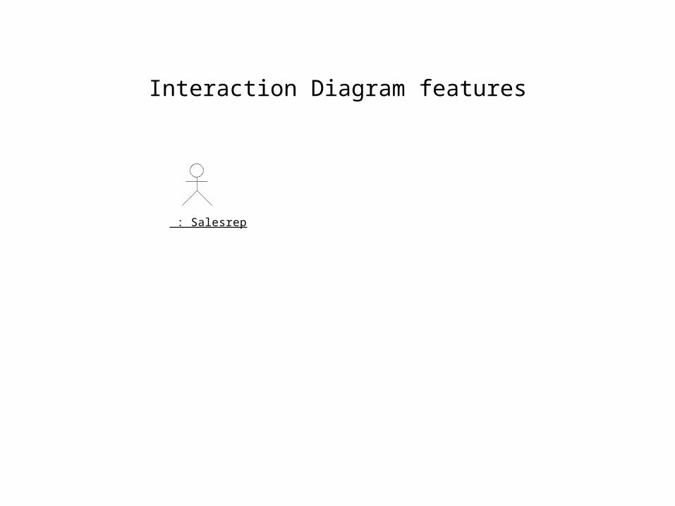
Interaction Diagram features
: Salesrep
: Order : OrderLine
1: cancel()2: *[for all order lines] cancel()

Iteration in a collaboration diagarm
: Salesrep
: Order
1: cancel()
: OrderLine
2: *[for all order lines] cancel()

Conditional messages
: Salesrep
: Order : OrderLine
1: [ status == pending ] cancel()2: *[for all order lines] cancel()
Condition in a sequence diagram

: Salesrep
: Order
1: [ status == pending ] cancel()
: OrderLine
2: *[for all order lines] cancel()
Conditional message in a collaboration

Branching
:A :B :C
[condition true] x()
[condition false] f()

:A :B
:C
1: [condition true] x()
1: [condition false] f()
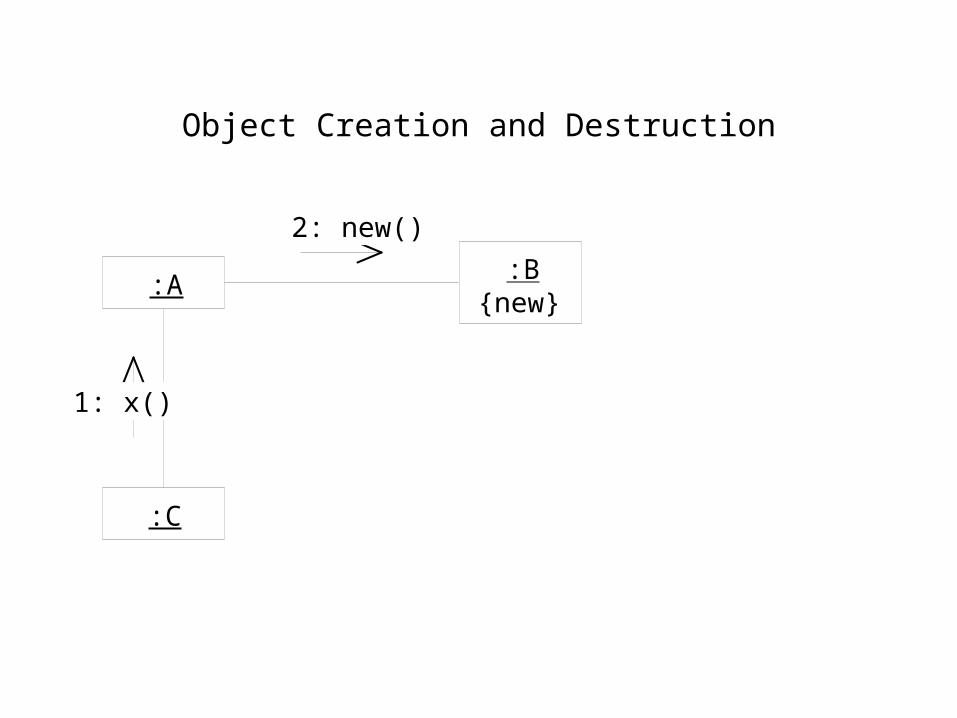
Object Creation and Destruction
:A:B
:C
1: x()
2: new()
{new}

:A :B
1: x()
:C
2: new()

Timing Constraints
:A :B
x
y
{ y - x < 5 ms }

Stereotypes for links
• <<association>>
• <<global>>
• <<local>>
• <<parameter>>
• <<self>>


CRC Cards
• Lists class, responsibilities, and collaborations
• Good for brainstorming
• UML interaction diagrams are more comprehensive

State Machines

State Machines
• May be used to model the dynamics of a system
• Used to model the behavior of a single object across all scenarios
• Useful for specifying the states that an object goes through in its lifetime, what triggers the transition, and how the object responds to those events that trigger the transition

• State machines are useful for objects that exhibit meaningful state-based behavior, i.e., when an object’s response to events depends on the state that it is in and when it is possible for the object to pass through a set of states (some of which may be meaningful), or when the order of execution of an object’s methods is important

State Machines
• A state is a particular condition that an object (with specific values for its attributes and links) is in during which time it may perform some activity or wait for the occurrence of an event
• Transitions from one state to another are triggered by events
• An event may be a signal (e.g., a hardware interrupt) or a message (e.g., the invocation of a method)

State Machines
• Activities may be performed by an object when it is in a particular state
• Time for an activity is not negligible
• Transitions are assumed to be instantaneous
• Actions carried out during transitions, therefore, take very little time

Parts of a state (Booch et al., 1999)
• Unique name (a string) - it could also be anonymous
• Entry and exit actions
• Transition to self, i.e., it remains in the same state
• Substates - nested structures which may involve sequential or concurrent substates
• Deferred events - queued to be handled by the object when it is in a different state

States
• Initial state is represented by a filled black circle
• Final state is represented by a filled black circle surrounded by a circle
• Initial and final states are called psuedostates

Triggers for Transitions
• When an event/message is received
• Event/message and a guarding condition occur
• A condition becomes true
• A certain amount of time elapses
• A triggerless transition may occur when the source state completes its activity
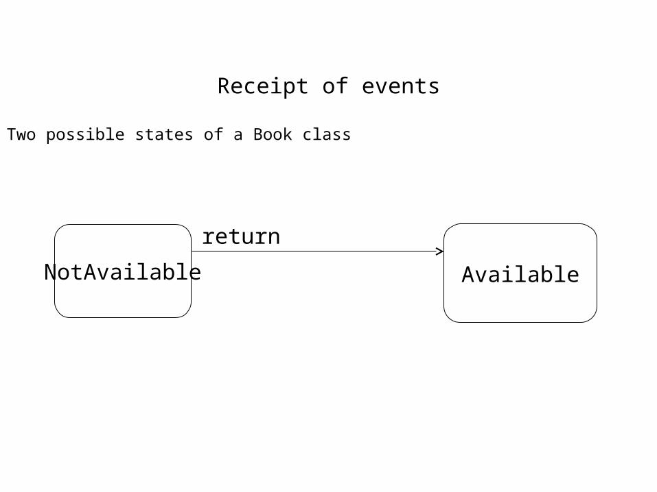
Receipt of events
Two possible states of a Book class
NotAvailable Available
return

Message and a guard condition
Two possible states of a Book class
NotAvailable Available
return [! onHold ]

Condition becomes true
Available NotAvailable
when (numberAvailable == 0)

Transition after a certain time
Possible states of a VCR
Stopped PowerOffafter(60 seconds)

Actions during a transition
Available BackOrdered
allocateFromInventory(quantity) [ quantity > currentInventory]^warehouse.backorderItem(item#, rorderQuantity)
when (currentInventory == 0 ) ^warehouse.backorderItem(item#, rorderQuantity)
itemAvailable(quantity) / currentInventory += quantity
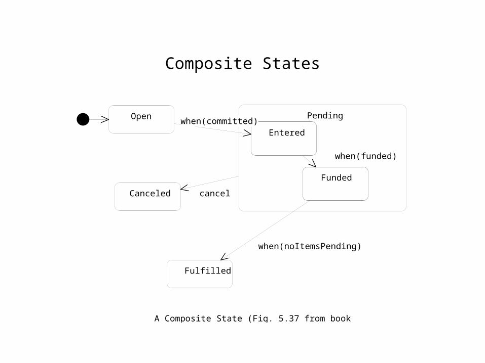
Composite States
Open Pending
Entered
Funded
Entered
Funded
Canceled
Fulfilled
when(committed)
when(funded)
cancel
when(noItemsPending)
A Composite State (Fig. 5.37 from book

Open Pending
Entered
Funded
Entered
Funded
Canceled
Fulfilled
when(funded)
cancel
when(noItemsPending)
Semantically identical to previous figure
when(committed)
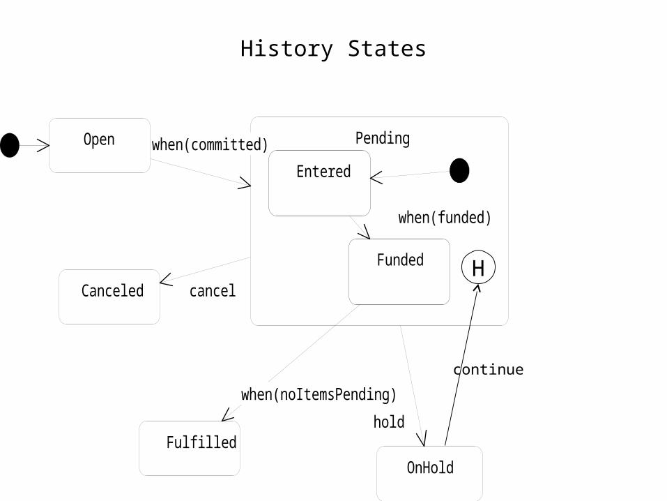
History States
Open Pending
Entered
Funded
Entered
Funded
Canceled
Fulfilled
when(funded)
cancel
when(noItemsPending)
when(committed)
OnHold
hold
H
continue

Shallow and Deep History
• The H is for shallow history, which is all right for one level of nesting
• Shallow history does not remember down to the innermost nested state
• Use deep history, represented by a H*, to remember down to the innermost nested state

Parallel State Machines
Available BackOrderedAvailable BackOrdered
when (currentInventory =
Listed UnListedListed UnListedremoveFromCatalog
addToCatalog
0)
....

Parallel State Machines
• Each of the two state machines (one for the Inventory and the other for the Catalog) executes in parallel
• Parallel state machines normally imply a lack of cohesion for the class
• In this example, management of inventory could be moved to a separate class ( remember Inheritance Coupling? from chapter 4)

Parallel States
Pending
Canceling
entry/creditIssuer.creditAccount
entry/ catalogItem.addToInventory
Canceled
entry/creditIssuer.creditAccount
entry/ catalogItem.addToInventory
cancel
cancel
credited
added
Join - bothmust complete
Fork - both statesentered at the same
time

Developing Dynamic Diagrams

Top-Down versus Bottom-Up Approach
• Top-Down Approach - start with use cases and step through scenarios to identify specific objects, their methods, and the links between objects
• Bottom-Up Approach - start with specific object methods, attribute, and links, and then refine/expand these responsibilities as each scenario is validated
• The primary purpose of both approaches is the same, viz., to identify the objects and their methods, attributes, and links, and also to have some idea of what each method must do

Design artifacts
• Design artifacts for both approaches include:
Use Cases and their specifications
Scenarios for each use case
Interaction diagram for each scenario
Statecharts for classes that have complex/interesting state-based behavior
Changes to the class diagram

Top-Down Approach
• Use case driven
• Steps include:
Identification of use cases
Specification of use cases
Definition of a scenario (an instance of the use case)
Drawing an interaction diagram for each scenario

Steps continued
Identification of object methods in the interaction diagrams
Alteration of class diagrams to ensure consistency with interaction diagrams
Development of state machines to understand the behavior of objects across scenarios, i.e., during its lifetime

Identifying Use Cases
• Jacobson’s Approach
Identify actors
Find out what interactions the actor initiates with the system and what interactions the system initiates with the actor
• Determine what use cases cause the creation, deletion, and modification of objects that belong to classes in your class diagram
• Verb phrases may reveal some use cases

Stock Trading Example
• The actor is the Service Representative
• Some use cases....
Enter a buy order
Enter a sell order
Cancel an existing order
Create a new account
Execute a transfer of stock into the system

Stock Trading example contd.
Execute a transfer of stock out of the system
Execute a transfer of cash into the system
Execute a transfer of cash out of the system
Query the system
What other use cases can you identify?
How did you identify them?

Description of each use case
• Describe the use case
• Detail the steps involved
• If necessary, draw an activity diagram
• Come up with a textual description that includes the trigger for the use case and pre- and post-conditions

A sequence diagram
: TradingSystemRep : Rep
1: enterBuyOrder

Another scenario
Rep : Rep : TradingSystem
: Account
1: enterBuyOrder2: getBalance

The “Happy” Path
Rep : Rep : TradingSystem
: Account newBuyOrder : BuyOrder
: Stock
1: enterBuyOrder2: getBalance
3: new
4: addBuyOrder(newBuyOrder)
Bottom-Up Design
• Identify classes
• Determine their responsibilities - state and behavior
• Validate responsibilities using relevant scenarios
• Draw an interaction diagram for each scenario to ensure that all responsibilities have been identified. Add/modify responsibilities as needed

Identifying classes and responsibilities
• Book, BookCopy, Video, VideoCopy, LibraryCard, LibraryMember, LoanTransaction
• A BookCopy must know:
Its unique item number
Its status (available or not)
It must be able to check itself out
It must be able to return itself (check in)

The Model
1..1*
1..*
1..1
LibraryMember
nameaddress
setName( )setAddress( )okToBorrow( )
1..11..1
LibraryCard
memberNumber : StringexpiryDate : Date
renew( )
1..11..1
0..*1..1
LoanTransaction
checkOutDate : DatedueDate : Date
isOverdue( )0..*1..1
rented1..1
0..*
BookCopy
call#
VideoCopy
video#
Lendable
item#
checkIn( )checkOut( )
<<Abstract>>1..1
0..*
1..1
1..*
Library
checkIn ()checkOut ()
<<facade>>
1..1*
1..*
1..1
LendableTitle
title
1..1
1..*
0..*
1..1
0..*
1..1

Validating the Model
• Use scenarios
• CheckOut scenario is as follows:
a) Clerk provides member# and item#
b) System checks to see if it is okay to borrow
c) System checks out the item

Assigning Behaviors
• Where should the method okToBorrow() really be?
• Who creates the Loan Transaction? (Lendable perhaps)
• Who should inform the LibraryMember object about the new LoanTransaction?
• How is the due date determined?

Checking out a book
rep:Clerk :Library aLendable:Lendable
:LendableTitle lt:LoanTransaction
:LibraryCard
1: checkOut(1001, 2345)2: okToBorrow()
3: checkOut()4: loanPeriod()
5: new(lc, aLendable, today + 14)6: addLoanTransaction(lt)

Flexibility Guidelines for Interaction Diagrams

Flexibility Guidelines
• Cohesion - class & method cohesion
• Distributing Behavior - Behavior of an activity to be done on a state should be in the object that has that state
• Extension vs reuse - extensibility often reduces reusability

Exception to cohesive classes
• The facade is an exception to the principle of having highly cohesive classes
• Although it is not cohesive, it serves the important purpose of reducing coupling

Class Cohesion
Consider the following partial class diagram..
Machine
statename
MaintenanceSchedule
dateLastMaintainedperiod
1..11..1 1..11..1

Class cohesion continued..
• Why can’t we combine the two classes (as the multiplicity is 1:1)?
a) Machine responds to a stimulus while MaintenanceSchedule produces a stimulus
b) They may not always be in a 1:1 relationship. Assuming that they are results in a design that is not extensible

• Write a one-sentence description of each responsibility. If it turns out to be a compound sentence that describes multiple activities, consider having another class
• Incorporating these one-sentence descriptions in the source code may help developers to maintain and enhance/extend the current design

Tradeoffs
• As mentioned earlier, a facade is an exception to cohesive classes, but one that is deemed necessary in the interests of reducing coupling
• Cohesion may also be sacrificed in the interests of systems performance

Distributing Behavior
• Behavior should be evenly distributed - avoid objects that have just data and no behavior
• Avoid controllers that make decisions based on state information obtained from other objects
• Reduce representational coupling by exposing the client to abstract rather that specific details

Distributing behavior contd.,
• Clients should use an assertive style that tells the service objects what to do rather than an inquisitive style where information is obtained from the service object and acted upon by the client

Examples
• Consider the following class diagrams..
ElevatorControl
handleRequest( )
Elevator
locationdirection
getProximity(req:Request):int0..*1..11..1 0..*
Elevator
locationdirection
direction()location()
ElevatorControl
handleRequest( ) 0..*1..11..1 0..*

Which of the two diagrams is better and why?
The second has more even distribution of behavior, allows for parallel computations, and is more extensible
The first may be desirable when centralized control is required, perhaps for performance reasons or because of other constraints

Stock Trading Example
Consider the following...
2: cancel()
:TradingSystem
:Order
1: getStatus()
:TradingSystem
:Order
1: cancel()
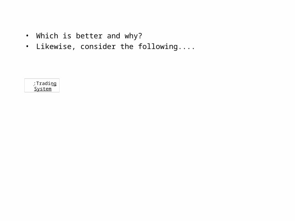
• Which is better and why?
• Likewise, consider the following....
:TradingSystem
:Account
1: getBalance()
:TradingSystem
:Account
1: fundBuy(amount)

• fundBuy(amount) is better because:
a) The state and behavior are in Account
b) If updates to balance have to be made, the behavior should be in the Account class
c) If there are different types of accounts, each of which has a different way of funding, then this approach is better
Note: We should really distinguish between balance and what is available
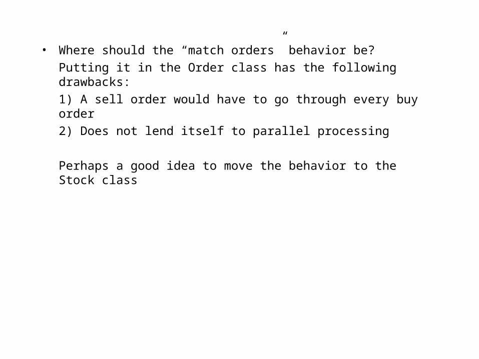
• Where should the “match orders” behavior be?
Putting it in the Order class has the following drawbacks:
1) A sell order would have to go through every buy order
2) Does not lend itself to parallel processing
Perhaps a good idea to move the behavior to the Stock class

Extension versus Reuse
• Extensibility often reduces reusability because application-specific methods may have to be added to a class
• This is a result of distributing behavior in order to avoid controller classes and to keep state and behavior together
If reuse is a major goal, a different set of guidelines may have to be used

Account Example
• For an Account class to be reusable, it should provide an interface/basic functionality that is common to all accounts
• An account that deals only with cash is less reusable than one that holds a variety of assets

Combining Extension and Reuse
• Application-specific class may use a more generic/reusable class through composition
1..1
Account
balance : float
deposit(amount:float)withdraw(amount:float)currentBalance()
StockTradingAccount
fundBuy(amount:float)unfundBuy(amount:float) 1..1

Architectural Models

Architectural Models
• Issues such as layering/subsystems, persistence, and deployment become important in large systems
• Decomposition is a useful technique for determining logical and/or physical blocks that make up the architecture of the system
• Logical blocks are layers or subsystems that are conceptual entities

• Physical blocks are things such as the hardware on which the logical blocks reside (as source or executables, e.g., *.cpp, *.exe)
• These blocks (logical and physical) may be nested
• Decomposition is mainly a top-down approach

Composition
• Composition is more of a bottom-up approach in which smaller units (such as specific use cases or classes) could be grouped together to form logical blocks
• Logical or physical considerations may be used to guide the grouping process

Architectural Perspectives
• Logical - emphasizes the layers/subsytems that comprise the overall system. A Package Diagram provides a visual model of a logical architecure
• Hardware - When multiple hardware units are used, a Deployment Diagram can be used to visualize their relationships and how the various logical and physical blocks are distributed

Architectural perspectives continued...
• Process - this view focuses on the threads and/or processes that are an integral part of concurrent applications. Issues such as synchronization, locking, throughput, and performance are important considerations in this view
• Implementation - A Component Diagram presents a view of all source, binaries, and executables, and their relationships.
• When used in conjunction (through superimposition) with static and dynamic diagrams, these views present a comprehensive understanding of the architecture

Logical architecture
• Conceptual grouping of layers/subsystems, guided by functional cohesion
• Each layer is responsible for a different function
• Example: Presentation, Application, and Persistence layers

PersistenceLayer
Application Layer
TradingSystem<<facade>>
AccountManagement
<<subsystem>
SecurityManagement
<<subsystem>>
OrderManagement<<subsystem>>
<<imports>>
<<imports>>
<<imports>>
<<imports>>
<<imports>>
<<imports>>
PresentationLayer
<<imports>>
<<imports>>

Logical Architecture
• A package contains logically related classes or logically related use cases
• Decomposition is typically used when the architecture is known before hand
• Having different packages as part of the overall system can help in assigning different aspects of software development to different teams

• Dependency between layers/packages can be shown using the <<imports>> stereotype
• It is possible to nest packages to any depth
• A class inside a package may or may not be visible to the outside world
• A plus (+) sign next to the class name implies that the class can be accessed by other packages
• A minus (-) sign next to the class name implies that the class is hidden from other packages

Criteria for partitioning
• Functional Cohesion
• Unit of reuse
• Access Control
• Delivery Units
• Physical configuration of components

Hardware Architecture
• Depicted as nodes and their interconnections
• A node is a computational unit with memory and quite possibly computing / processing capability
• Nodes are physically connected to other nodes

Hardware Architecture...
• A Deployment Diagram shows nodes and their relationships
• Cardinality constraints may be shown both for the nodes and their relationships

Deployment Diagram
Account Server
Client
Order Server
Account Database Server
Order Database Server
<<ethernet>><<ethernet>>
• Deployment Diagrams are useful for showing the hardware architecture of:
a) Embedded Systems
b) Client/Server Systems
c) Fully Distributed Systems
• A deployment diagram instance may be drawn to show an occurrence of node instances and their connections
• Nodes from the Deployment Diagram may be superimposed on class (& package) and interaction (mainly collaboration) diagrams


• Use the <<becomes>> stereotype for a dependency to show object migration from one processor to another
• Example(Fig. 8.16, Page 288), an order object from the Order Database Server “migrates’ to the Order Server when it is retrieved from the database

Process Architecture
• Most applications use some form of concurrency to maximize system throughput and to improve the overall performance of the system
• Processes and threads are frequently used to achieve concurrency
• A process is a heavyweight flow of control, independent of other processes with which it runs concurrently

• Inter-process switching and communication are relatively expensive
• A thread is a lightweight flow of control that runs concurrently with other threads within a process
• Threads within a process share the same heap space and, therefore, it is relatively inexpensive to switch between threads

• An active object is one that has the ability to initiate control activity on its own by virtue of owing a thread or a process
• The spawning of processes and threads is mainly a function of the Operating System
• Languages such as Java support multithreading
• An active object in Java is an instance of a class that either specializes the Thread class or implements the runnable interface

Class Synchronization
• The use of threads requires careful thought in order to avoid integrity problems
• Designs should take particular care to avoid improper locking and deadlock problems
• Levels of locking include:
• A sequential class or method
• A concurrent class or method
• A guarded class

Sequential class or method
• No locks are used
• An instance can have two (or more) of its methods running concurrently
• Does not guarantee integrity under concurrent operations
• A sequential class has only sequential methods

Concurrent class or method
• A lock on the instance is obtained when a concurrent method is run
• Lock is released when the method completes execution
• If a lock on the object is not available, the calling thread or process waits
• All methods in a concurrent class are concurrent

Guarded class
• Client is responsible for locking and unlocking an object whose class is guarded
• The methods to lock and unlock are in the guarded class
• If an instance of the guarded class is locked, the client must wait until it is available
Concurrent or Guarded?
• In most cases, concurrent locking is preferable because:
1. Client code is more readable and maintainable
2. No dependency on client
3. It may be easier to avoid deadlocks
4. Clients are immune to changes made to the classes on whose services they depend

Guarded is preferable when...
• The client wishes to treat more than method as a single, atomic operation
• Example: Applying a stock split to all StockHolding and Order instances for a given security

Synchronization control of classes
• Classes whose instances are likely to be affected by the concurrent execution of two or more use cases need to be synchronized

Process or Thread Synchronization
• Processes or threads may also have to be synchronized
• Operating Systems have mechanisms for synchronizing processes
• A Rendezvous Pattern may be used to synchronize threads

Synchronization options
• Depending on how long a client is willing to wait for a lock on an instance, one of the following schemes may be used:
1. Asynchronous
2. Synchronous
3. Timeout
4. Balking
5. Simple
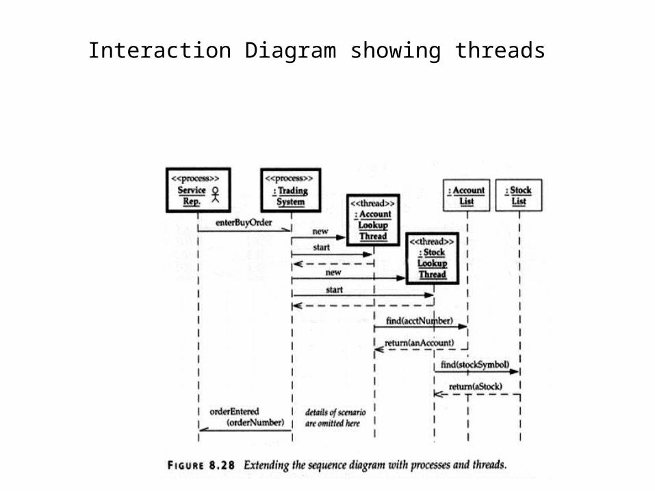
Interaction Diagram showing threads


Process Scheduling
• How long a process executes depends on whether preemptive or non-preemptive scheduling is being used
• The order of execution depends on whether it is priority-based, round-robin, or a combination

Implementation Architecture
• A component diagram is used to show components and their relationships
• A component such as a source file (eg., a cpp or a .h file), binary, or an executable is physical and substitutable
• A dependency relationship often exists between components

Order.cpp
Order.hCustomer.h

• Interface dependencies may be shown on a component diagram
• Superimposing the hardware architecture (Deployment Diagram) on the implementation architecture gives an idea of how the components are distributed in an application

Reuse

Reuse
• Avoid building from scratch
• Faster development time
• Higher quality
• Different levels of granularity (single class to a framework)
• Reuse may be implementation-based (e.g., a class) or conceptual (e.g., a design pattern)
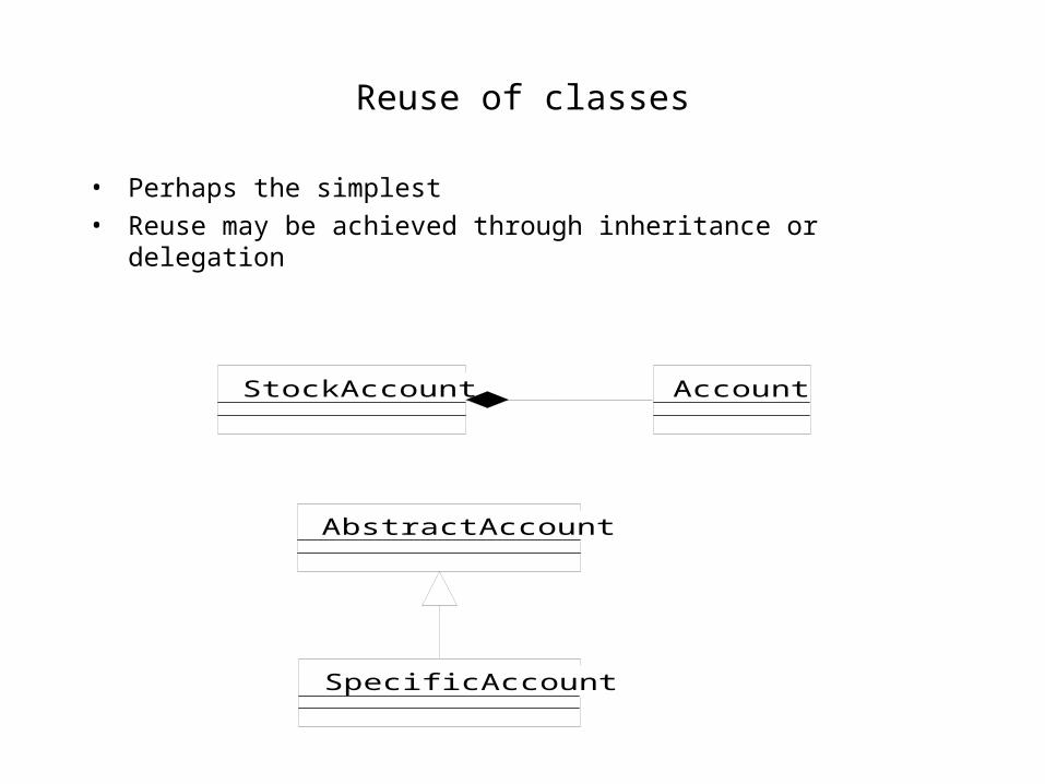
Reuse of classes
• Perhaps the simplest
• Reuse may be achieved through inheritance or delegation
AccountStockAccount
AbstractAccount
SpecificAccount

Inheritance or delegation
• Inheritance may be easier to implement, but some methods may have to be overriden
• Inheritance commits relationships at compile-time
• Inheritance is not very useful if some of the public methods have to be hidden from the client
• Inheritance assumes that subclasses are associated with only one superclass

Inheritance vs delegation
• Inheritance may be the only option if there is a need to use protected methods and fields of a library class
• Delegation, on the other hand, gives run-time flexibility

Generic Programming & Reuse
• C++ uses the notion of templates to provide generic classes that may be reused
• The more abstract the class the more reusable it is
• Class-based reuse is easier for application-independent abstractions

Component reuse
• Components are a coherent unit that realize a set of interfaces which they offer to other components
• Components are physical elements that can be replaced
• The purpose of a component is usually well-defined in the context of an application
• A component usually consists of many classes and is thus a larger scale building block than a class

Component Example
Inventory Management<<component>>
Method parameters are not shown
+InventoryManagementFacade
allocateFromInventory()addToInventory()currentInventory()defineInventoryItem()removeInventoryItem()
1..1
-ItemRegistry
find(item#:int)1..1
-InventoryItem
allocateFromInventory()addToInventory()currentInventory()
0..1
item# : type
0..1
item# : type
An Inventory Management Component

Framework Reuse
• Customization of components does not normally involve internal specialization
• External behavior and addition of other components is what allows for component customization
• Frameworks allow for internal specialization

• The commonality of many applications are often embodied in a framework, e.g., handling reservations for different applications typically involves activities that are common to all entities being reserved
• A white-box framework allows for application-specific implementation through inheritance (by offering set of abstractions whose interfaces are defined and implemented)

• A black-box framework allows for customization through additional classes that implement the interfaces defined in the framework, i.e., you just plug in classes that conform to the interface or role
• To summarize, with white-box frameworks you must understand the classes in them in order to tailor them for an application and in black-box frameworks you must understand what interfaces have to be implemented


Black-Box Framework Example


Role-Based Design
• Clients should be coupled to roles rather than to specific classes
• This gives more flexibility
• Use interfaces to accomplish this

How do we improve this?
Empty implementations
Client
Device
reset()pause()resume()poll()
<<abstract>>
0..*0..* 0..*0..*
D1
reset()pause()poll()resume()
D2
reset()pause()resume()
D3
reset()poll()


References
• Booch, Rumbaugh, and Jacobson, “The Unified Modeling Language User Guide,” Addison-Wesley, 1999
• Coad and Mayfield, “Java Design – Building Better Apps and Applets,” Yourdon Press Computing Series, 1999
• Fowler with Kendall Scott, “UML Distilled: Applying the Standard Object Modeling Language,” Addison-Wesley, 1997
• Gamma, Helm, Johnson, and Vlissides, “Design Patterns: Elements of Reusable Object-Oriented Software,"”Addison-Wesley, 1995
• Pooley and Stevens, “Using UML – Software Engineering with Objects and Components,” Addison-Wesley, 1999
• Richter, Charles, “Designing Flexible Object-Oriented Systems with UML,” Macmillan Technical Publishing, 1999
• Schneider, Geri and Winters, Jason, “Applying Use Cases – A Practical Guide,” Addison-Wesley, 1997