modeling ecris plasma using 2d gem (generalized … · far-tech, inc., 3550 general atomics court,...
TRANSCRIPT
FAR-TECH, Inc., 3550 General Atomics Court, MS 15-148, San Diego, CA 92121Tel: (858) 455-6655, Fax (858) 450-9741 www.far-tech.com
Modeling ECRIS Plasma Using 2D GEM
(Generalized ECRIS Model)
Liangji Zhao, Jin-Soo Kim, Brian Cluggish

2
Abstract
• The GEM (General ECRIS Model) code is developed by FAR-TECH,Inc. to model plasmas in ECRIS devices using experimental knobssuch as magnetic field, rf and the geometry of the device.
• The code models ECRIS plasma electrons by the bounce-averagedFokker-Planck equation, ions as fluid and neutrals by particlebalancing.
• It has been extended to include 2D (axial and radial) spatial featuressuch as 2D ECR heating and ion radial diffusion. The convergenceand consistency of the code have been studied. It is parallelizedusing the MPI technique to boost the calculation speed.
• Example results of simulated 2D profiles of ECRIS plasma and theradial dependence of CSD (charge state distribution) will bepresented.
3
Extension of GEM 1D(z) to 2D(r,z)
• GEM 1D simulates ECRIS plasma along the axis.
– Use only experimental knobs as inputs.– Advance hybrid model: bounce-averaged Fokker-Planck
EDF modeling, ion fluid modeling, and neutral particlebalancing modeling.
– Has produced consistent results with the experiments.
• GEM 2D simulates ECRIS plasma in both radial and axialdirections.
– The importance of radial dependence of ECR ion sourcesis recognized experimentally.
– GEM 2D can model the football shape ECR resonancesurface more accurately.

4
GEM 2D can simulate ECRIS device
Vextract
Grounded tube
ECR Plasma
Plasma sheath
Groundedelectrode
1+ ion beamn+ ion beam
Microwaves
Magnetic field lines
Modeled by GEM
Simulation parameters for ANLECR-I device:RF: 323 W @ 10 GHz
Vessel: 3.8 cm radius,29 cm length
Gas pressure: 10-6 – 10-7 Torr, Oxygenne ~ 1018 m-3
Te ~ 10-100eV (edge)1 – 10’s keV (core)
Ti ~ 1eV
5
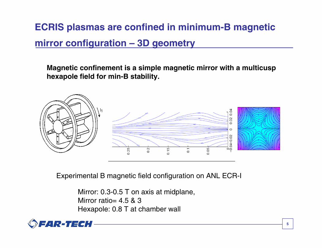
ECRIS plasmas are confined in minimum-B magnetic
mirror configuration – 3D geometry
Magnetic confinement is a simple magnetic mirror with a multicusphexapole field for min-B stability.
Experimental B magnetic field configuration on ANL ECR-I
Mirror: 0.3-0.5 T on axis at midplane,Mirror ratio= 4.5 & 3Hexapole: 0.8 T at chamber wall
6
Magnetic field lines
Z
0.00 0.05 0.10 0.15 0.20 0.25 0.30
R
-0.04
-0.02
0.00
0.02
0.04
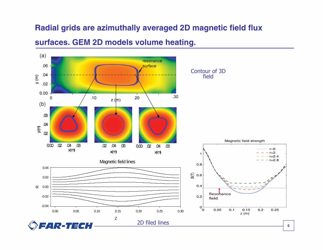
Radial grids are azimuthally averaged 2D magnetic field flux
surfaces. GEM 2D models volume heating.
Contour of 3Dfield
2D filed lines

7
2D ECR resonance surface
2,
0 1/2,
res
res
B z r B
Brf rf res
res
BD z r D e
B
2
2
1
1c
2D modeling of rf diffusion term:

8
GEM models ion, electron, and neutral dynamics
IONS:Cold and highly collisional,Fluid ion model
ELECTRONS:bounce time << collision timeNon-Maxwellian electron distribution function (EDF)1D bounce-averagedFokker-Planck electron code fe(v,)
NEUTRALS:Unimpeded by magnetic fields:Density profile determined by particlebalance
Bz
z
9
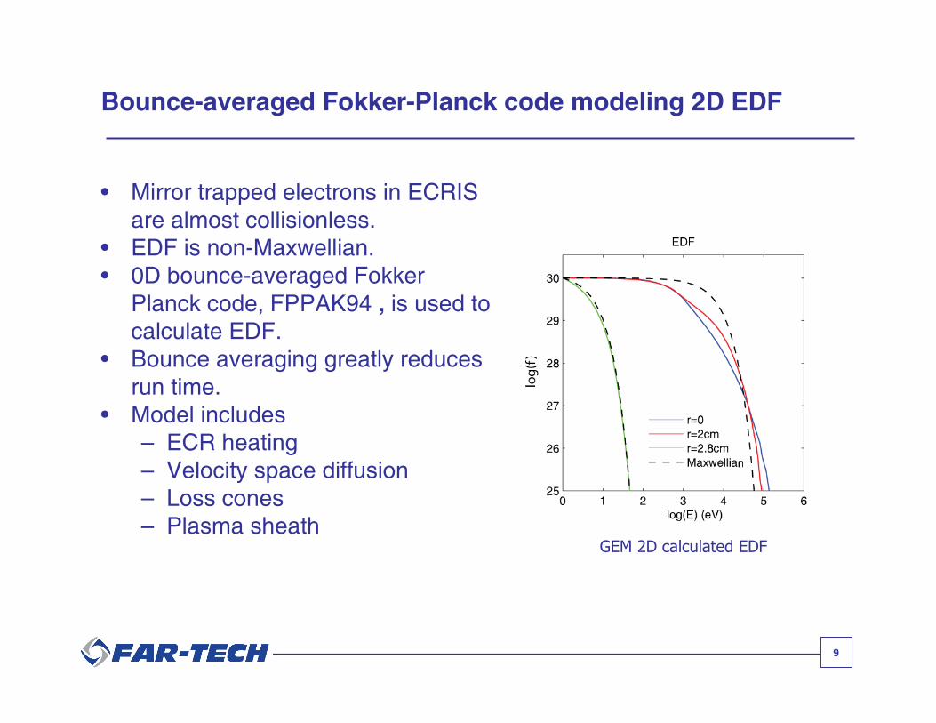
Bounce-averaged Fokker-Planck code modeling 2D EDF
• Mirror trapped electrons in ECRISare almost collisionless.
• EDF is non-Maxwellian.• 0D bounce-averaged Fokker
Planck code, FPPAK94 , is used tocalculate EDF.
• Bounce averaging greatly reducesrun time.
• Model includes– ECR heating– Velocity space diffusion– Loss cones– Plasma sheath
GEM 2D calculated EDF
10
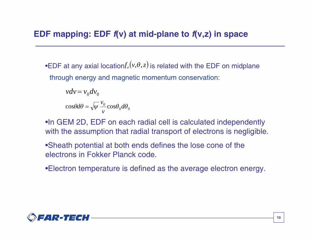
EDF mapping: EDF f(v) at mid-plane to f(v,z) in space
zvfe ,,
00dvvvdv
000 coscos dv
vd
•EDF at any axial location is related with the EDF on midplane
through energy and magnetic momentum conservation:
•In GEM 2D, EDF on each radial cell is calculated independentlywith the assumption that radial transport of electrons is negligible.
•Sheath potential at both ends defines the lose cone of theelectrons in Fokker Planck code.
•Electron temperature is defined as the average electron energy.

11
• Assume neutral density distribution has no radial dependence and neutraltemperature is room temperature everywhere in space.
• Neutral losses inside the plasma due to ionization and charge-exchangeare balanced by neutral gas input from outside of the plasma:
Neutrals: volume averaged modeling
cxzcxionizationz
zzzzzgpz
VRnRRVn
nnAnnAnnAv
,1,0
01,0101,01,00
)(
))()()(5.0
Z
A z A z+1A pz

12
GEM 2D Ion fluid modeling radial and axial transport
• The 2D ion continuity equation is solved using upwind method:
qrjqjqjqjz
z
outqj
inqj
qjvrn
rrunA
zASS
t
n,,,,,,
, 11
• Ions are cold, Ti~1 eV, and highly collisional– Mean free path < 1 mm– Ions all have same axial speed– Radial and azimuthal speed are different for each ion.
• Full 2d2v EDF used to calculate ionization rates:– A+n + e- A+n+1 + 2e-
• Ion loss rate is limited by electron confinement in magnetic mirror.

13
Equations of 2D fluid modeling
The ion continuity equation:
qrjqjqjqjz
z
outqj
inqj
qj vrnrr
unAzA
SSt
n,,,,,,
, 11
The radial and azimuthal velocities are calculated from ionmomentum equations:
j
qcj
pkpkqjpkqjpkjkqj
jk
jqj
jk
qj
in
qj
qj
inqj
qcj
qrj
pkprkqrjpkqjpkjkqj
jkr
jqj
jkr
qrj
in
qrj
qj
inqjqj
jqj
qjB
qcj
rqj
m
qeB
vvKnnF
mn
Fvv
n
Sv
vvKnnF
mn
Fvv
n
S
r
n
mn
Tk
B
Ev
,
,,,,,,,
,
,,
,
,
,
,
,,,,,,,
,
,,
,
,,
,
,
,
,
)(
1
)(
1
The axial ion momentum equation is z
j
qj
ininqj
qj
qj
qjj
qjBqj
qj
qj
qrj
qj
Em
qeuuS
n
z
n
nm
Tk
z
uu
r
uv
t
u
,,
,
,
,
,,
,
,
,
,
1
1
14
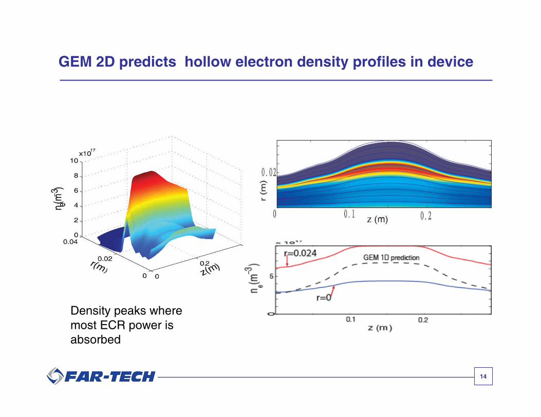
GEM 2D predicts hollow electron density profiles in device
Density peaks wheremost ECR power isabsorbed
15
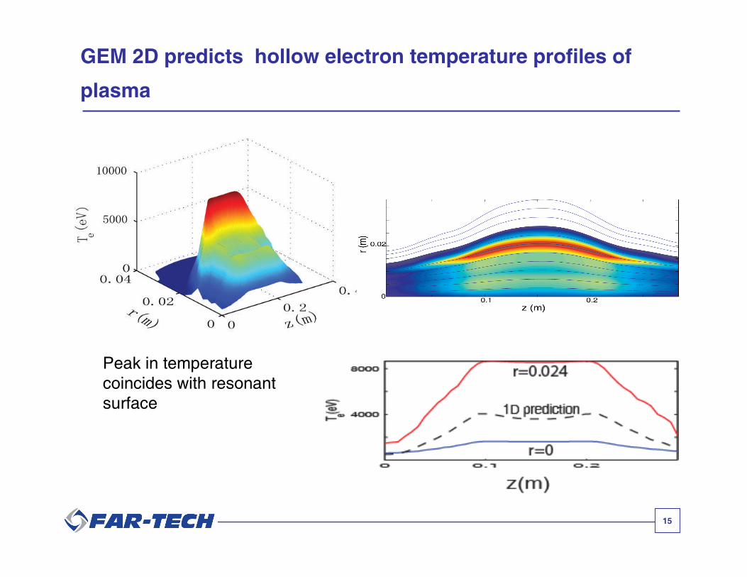
GEM 2D predicts hollow electron temperature profiles of
plasma
Peak in temperaturecoincides with resonantsurface

16
GEM 2D predicts hollow CSD of extracted ion sources
Extracted Charge State Distribution (CSD)
GEM 2D
ANL ECR-I data
Radially integrated CSD andexperimental data
CSD at different radial positions

17
Experimental evidence of the hollow profile of ECRIS plasma*
* S. Biri, ICIS03, Dubna, Russia

18
Summary
• GEM 1D is successfully extended to 2D:
– 3D ECRIS magnetic field modeling and 2D azimuthally averaged field.
– 2D ion fluid modeling.
– 2D ECR heating modeling.
– GEM 2D is parallelized using MPI.
– Improved stability by using upwind method.
• GEM 2D results are cross-checked with GEM 1D.
• The radial dependence of plasma profiles and CSD are consistent withthe experimental observations.