modeling of transmission lines - guceee.guc.edu.eg/courses/electronics/elct908 distributed...
TRANSCRIPT
Modeling of Transmission Lines
Electric Power Transmission
• The electric energy produced at generating stations is
transported over high-voltage transmission lines to utilization
points.
• The trend toward higher voltages is motivated by the
increased line capacity while reducing line losses per unit of
power transmitted.
• The reduction in losses is significant and is an important aspect
of energy conservation.
• Better use of land is a benefit of the larger capacity.
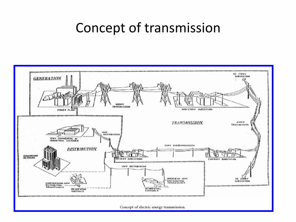
Concept of transmission
TRANSMISSION LINE PARAMETERS
• An electric transmission line is modeled using series
resistance, series inductance, shunt capacitance, and shunt
conductance.
• The line resistance and inductive reactance are important.
• For some studies it is possible to omit the shunt capacitance
and conductance and thus simplify the equivalent circuit
considerably.
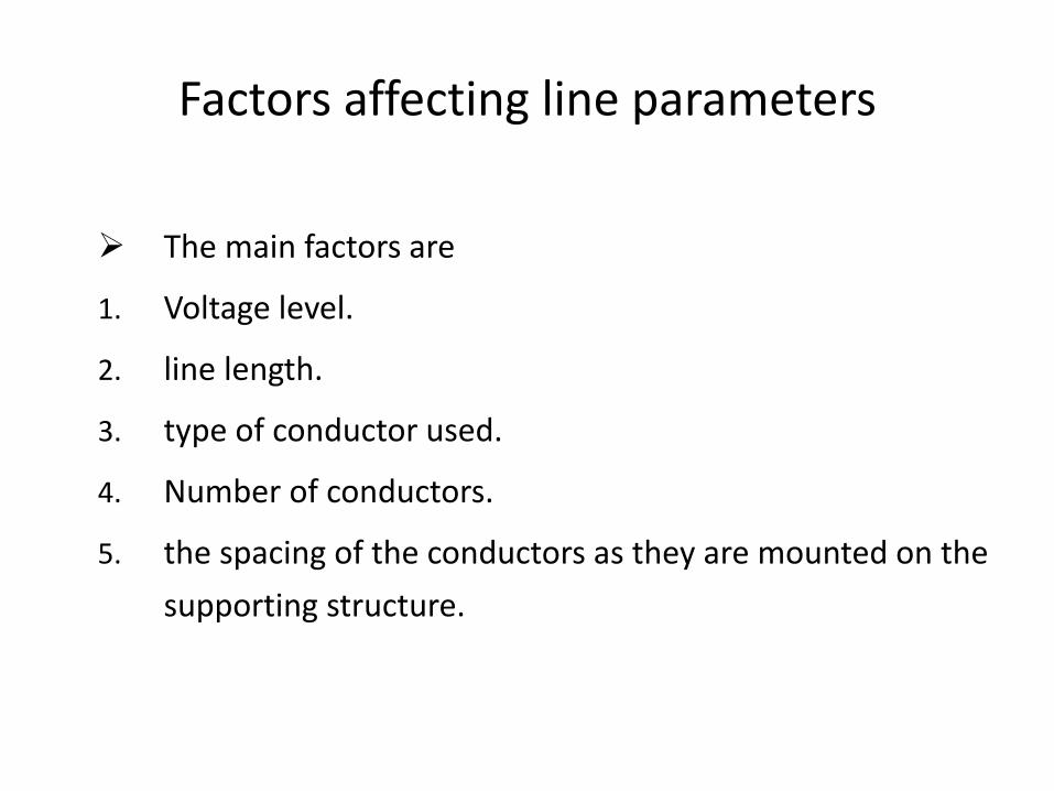
Factors affecting line parameters
The main factors are
1. Voltage level.
2. line length.
3. type of conductor used.
4. Number of conductors.
5. the spacing of the conductors as they are mounted on the
supporting structure.
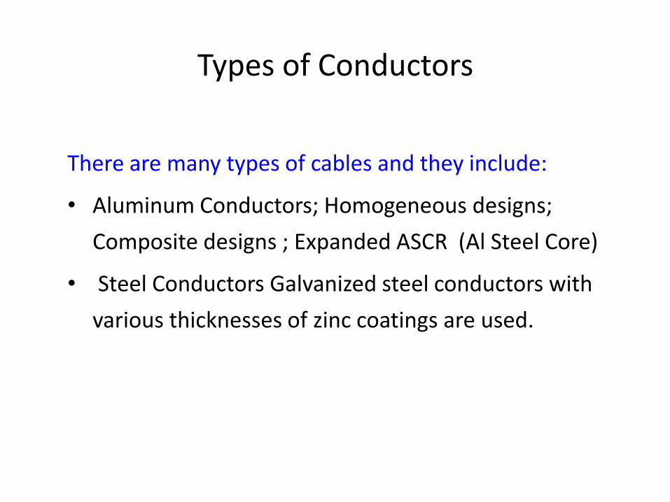
Types of Conductors
There are many types of cables and they include:
• Aluminum Conductors; Homogeneous designs;
Composite designs ; Expanded ASCR (Al Steel Core)
• Steel Conductors Galvanized steel conductors with
various thicknesses of zinc coatings are used.
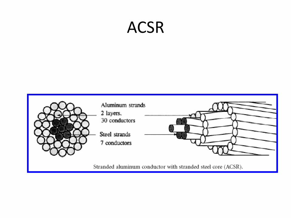
ACSR
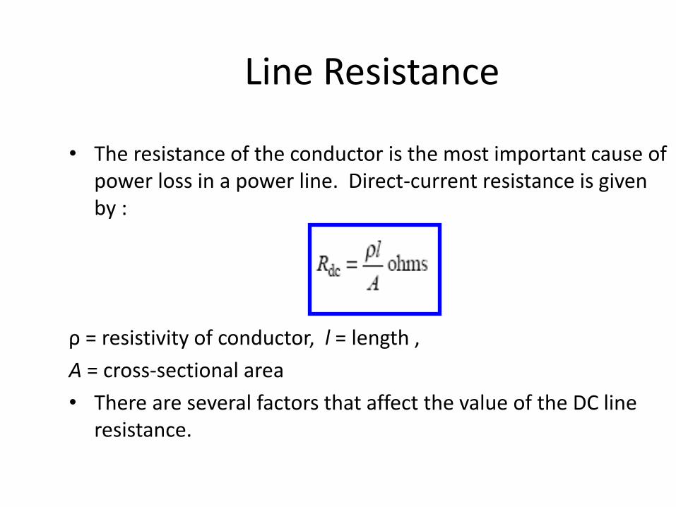
Line Resistance
• The resistance of the conductor is the most important cause of power loss in a power line. Direct-current resistance is given by :
ρ = resistivity of conductor, l = length ,
A = cross-sectional area
• There are several factors that affect the value of the DC line resistance.

Factors affecting line resistance
1. Conductor stranding.
2. Skin Effect : When ac flows in a conductor, the current is
not distributed uniformly over the conductor cross-
sectional area. This is called skin effect and is a result of
the non-uniform flux distribution in the conductor. This
increases the resistance of the conductor.
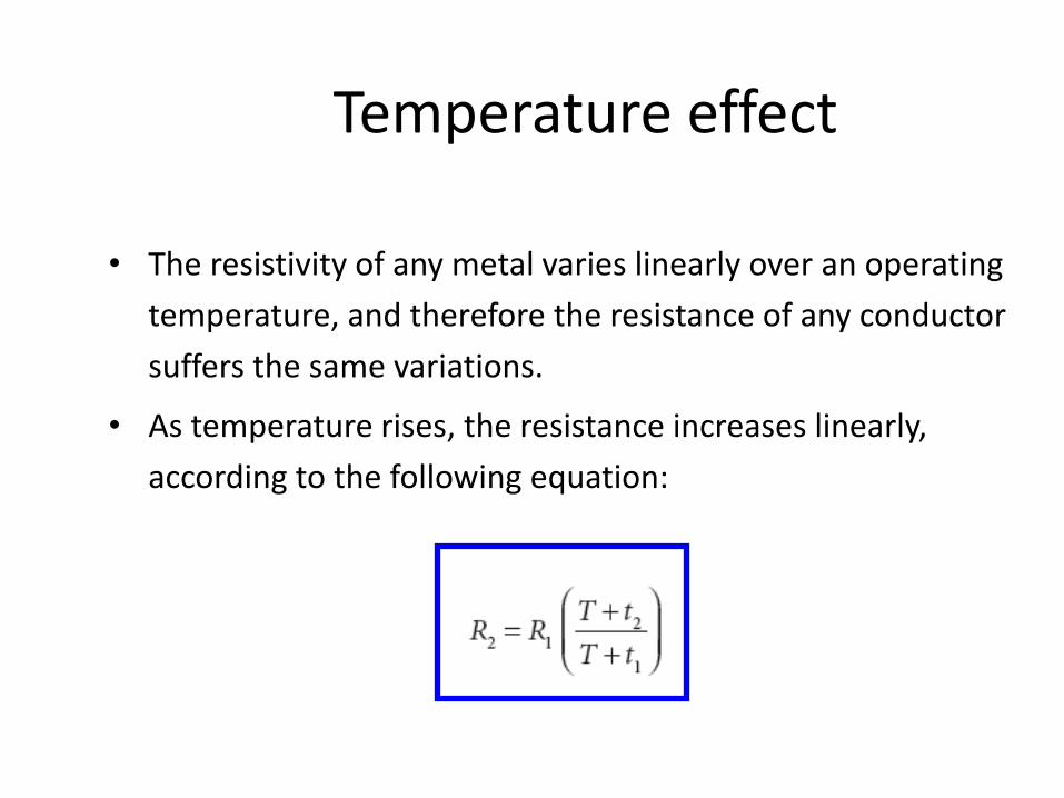
Temperature effect
• The resistivity of any metal varies linearly over an operating
temperature, and therefore the resistance of any conductor
suffers the same variations.
• As temperature rises, the resistance increases linearly,
according to the following equation:
LINE INDUCTANCE
• The inductive reactance is by far the most dominating
impedance element.
• The inductance depends on the size of the conductors,
the spacing between the conductors, transposition, the
arrangement of conductors and the material of each
conductors.
• Several arrangements are used in modern transmission
systems.
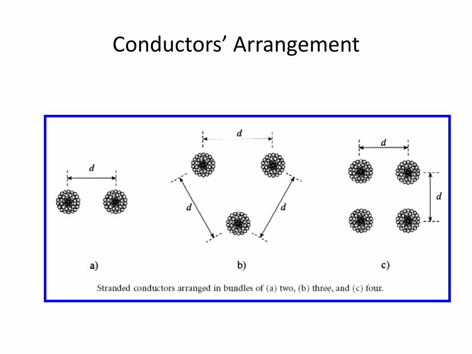
Conductors’ Arrangement
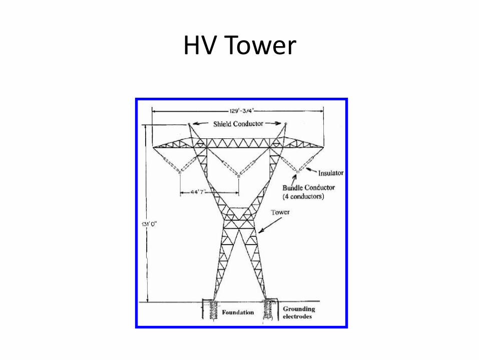
HV Tower
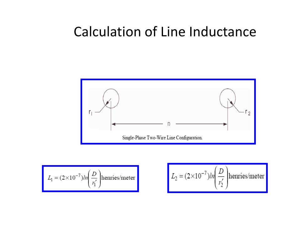
Calculation of Line Inductance
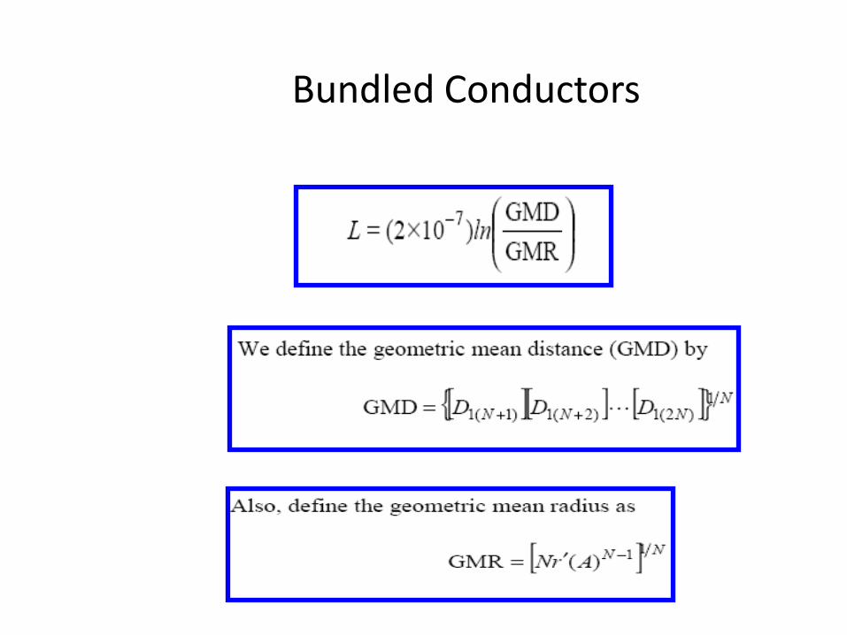
Bundled Conductors
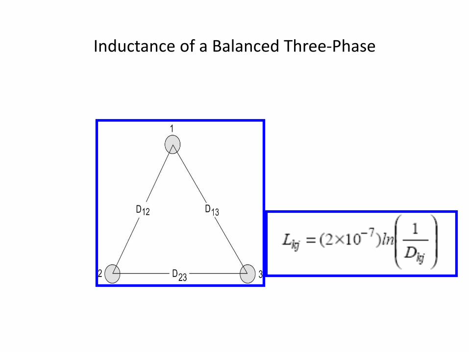
Inductance of a Balanced Three-Phase
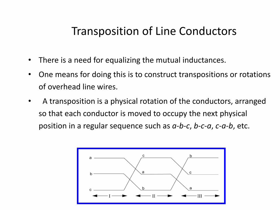
Transposition of Line Conductors
• There is a need for equalizing the mutual inductances.
• One means for doing this is to construct transpositions or rotations
of overhead line wires.
• A transposition is a physical rotation of the conductors, arranged
so that each conductor is moved to occupy the next physical
position in a regular sequence such as a-b-c, b-c-a, c-a-b, etc.
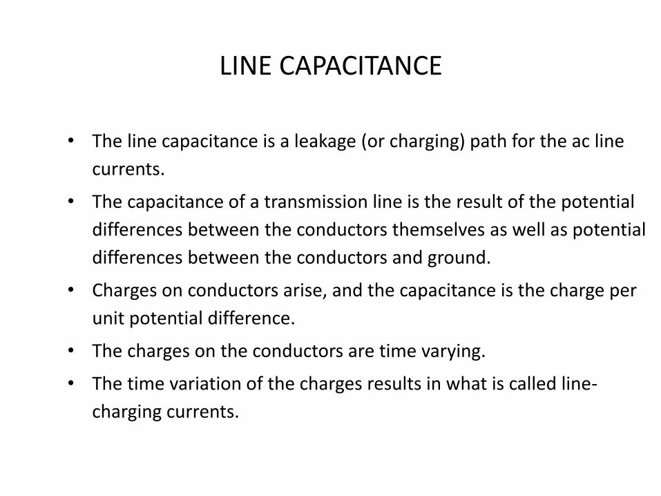
LINE CAPACITANCE
• The line capacitance is a leakage (or charging) path for the ac line
currents.
• The capacitance of a transmission line is the result of the potential
differences between the conductors themselves as well as potential
differences between the conductors and ground.
• Charges on conductors arise, and the capacitance is the charge per
unit potential difference.
• The charges on the conductors are time varying.
• The time variation of the charges results in what is called line-
charging currents.
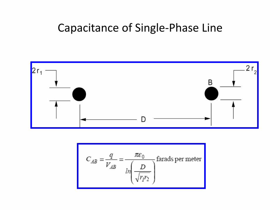
Capacitance of Single-Phase Line
TRANSMISSION LINE MODELS
• A transmission line is defined as a short-length line if its
length is less than 80 km (50 mi).
• In this case, the capacitive effect is negligible and only the
resistance and inductive reactance are considered.
• Assuming balanced conditions, the line can be represented
by the equivalent circuit of a single phase with resistance
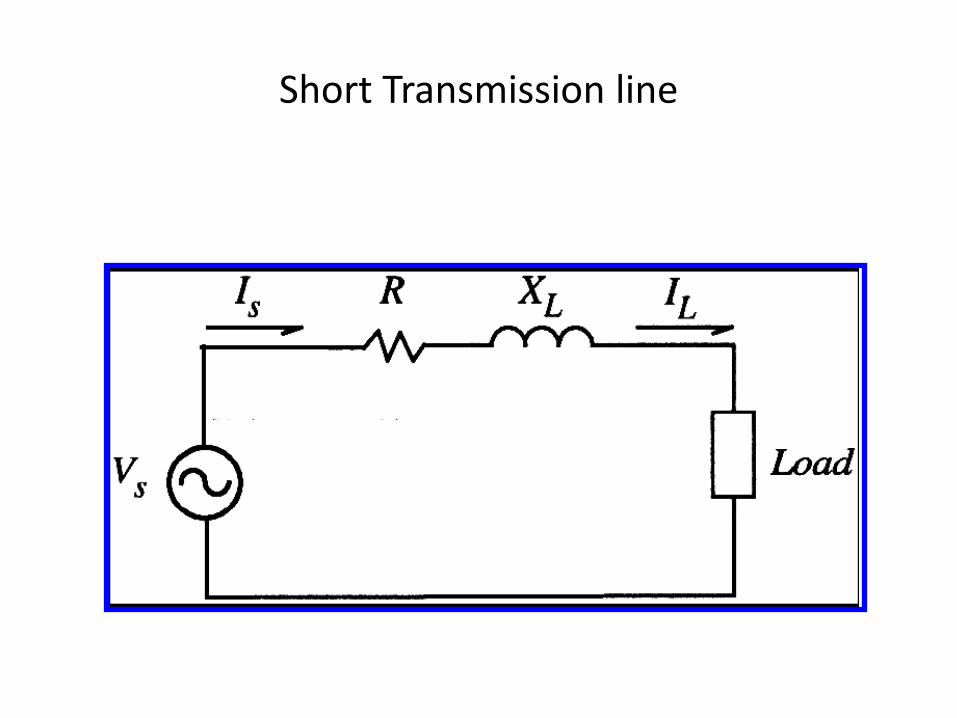
Short Transmission line
Medium T.L.
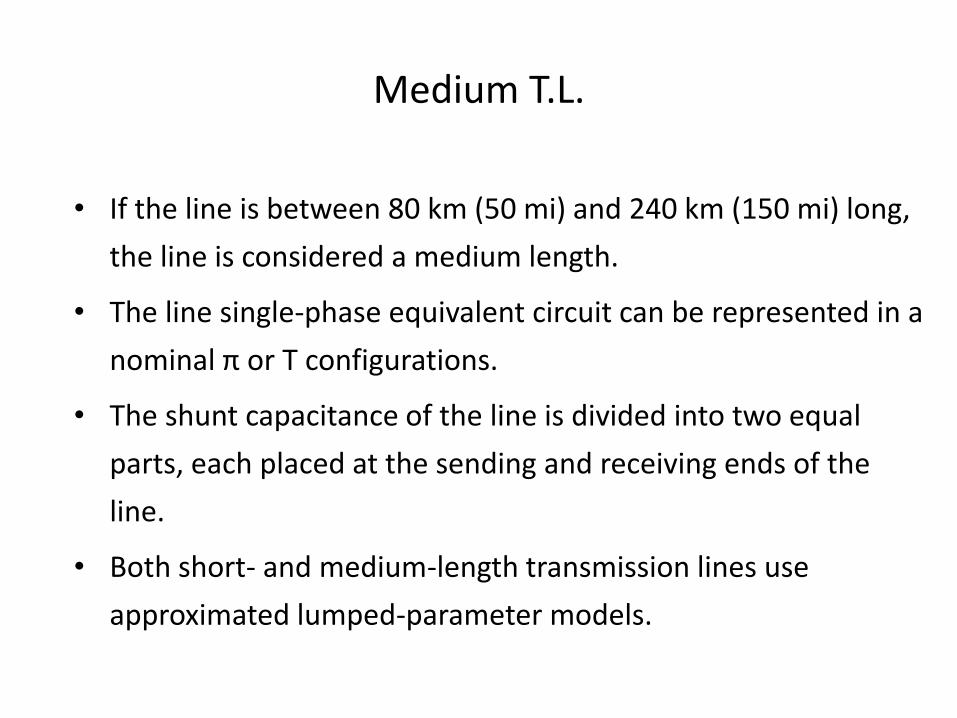
• If the line is between 80 km (50 mi) and 240 km (150 mi) long,
the line is considered a medium length.
• The line single-phase equivalent circuit can be represented in a
nominal π or T configurations.
• The shunt capacitance of the line is divided into two equal
parts, each placed at the sending and receiving ends of the
line.
• Both short- and medium-length transmission lines use
approximated lumped-parameter models.
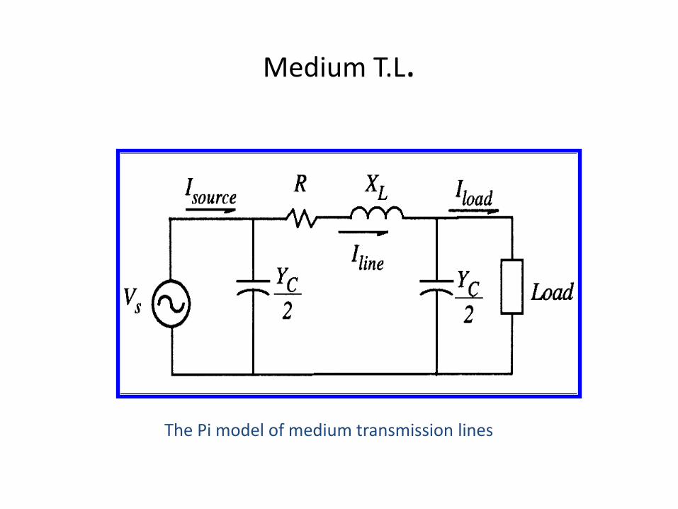
Medium T.L.
The Pi model of medium transmission lines
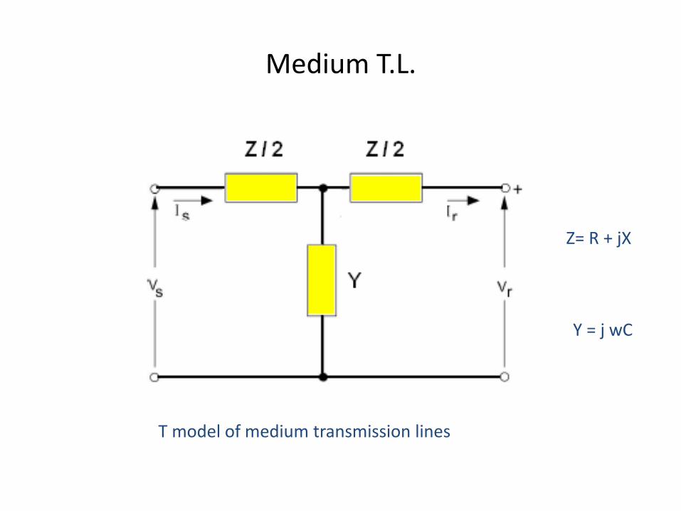
Medium T.L.
T model of medium transmission lines
Z= R + jX
Y = j wC
Long T.L.
• If the line is more than 240 km long, the model must
consider parameters uniformly distributed along the line.
• The appropriate series impedance and shunt capacitance are
found by solving the corresponding differential equations,
where voltages and currents are described as a function of
distance and time with the assumptions:
1. The line is operating under sinusoidal, balanced, steady-state
conditions. 2. The line is transposed.
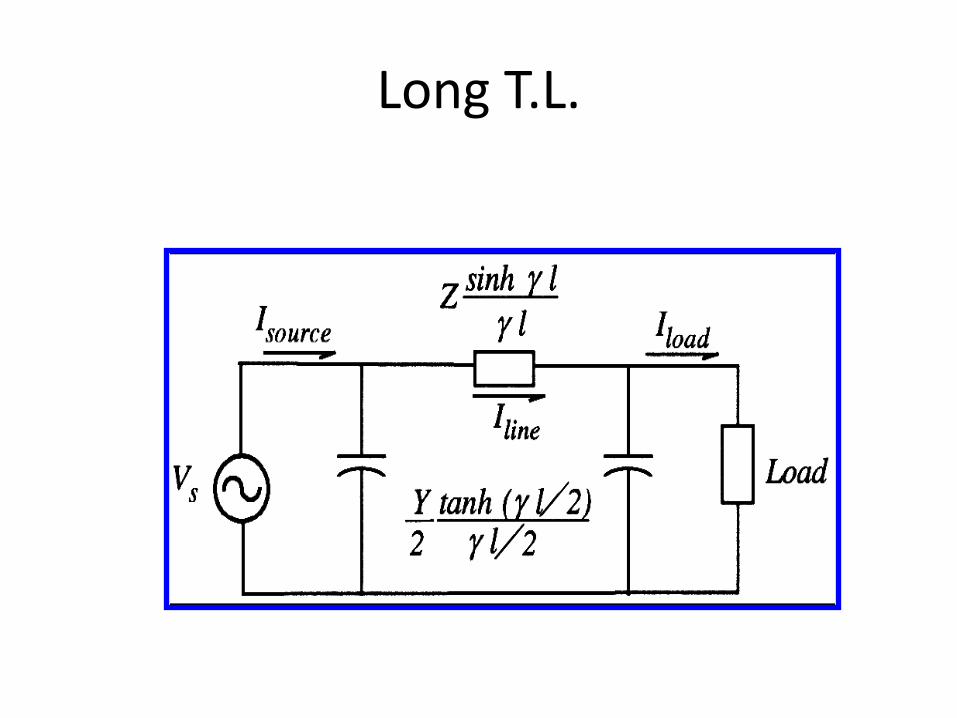
Long T.L.
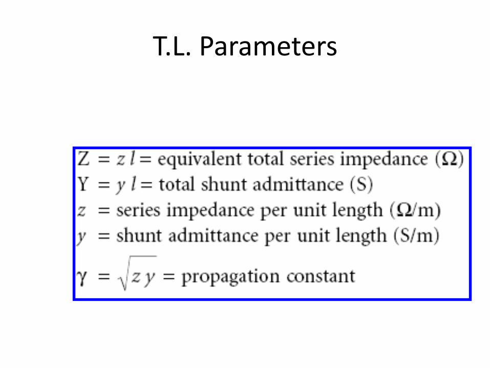
T.L. Parameters