modelling and control of hybrid stepper...
TRANSCRIPT

Modelling and Control of Hybrid Stepper MotorS.S. Harish*, K. Barkavi**, C.S. Boopathi*** and K. Selvakumar****
Abstract: This paper focuses on modeling, simulation and control of two phase Hybrid Stepper Motor (HSM). The simulation model is developed, in ‘MATLAB’ to study the transient performance of the motor under various excitation schemes. Simulation results are verified for HSM model ST601 and ST1701 step angle-1.8o, torque-2 Kg. cm and 125 Kg. cm. National Instruments LABVIEW is used with DAQ card PCI 6221 for open loop control. Resonance phenomenon is obtained experimentally and explained in theory. Closed loop current control is employed to maintain the speed for various loads.
1. INTRODUCTIONStepper motors are electromagnetic incremental-motion devices which convert digital pulse inputs to analog angle outputs. Their inherent stepping ability allows for accurate position control without feedback. They can track any step position in open-loop mode; consequently no feedback is needed to implement position control. Stepper motors deliver higher peak torque per unit weight than DC motors; in addition, they are brushless machines and therefore require less maintenance. All of these properties have made stepper motors a very attractive selection in many position and speed control systems, such as in computer hard disk drivers and printers, XY-tables, robot manipulators, etc. Although stepper motors have many salient properties, they suffer from an oscillation or unstable phenomenon. This phenomenon severely restricts their open-loop dynamic performance and applicable area where high speed operation is needed. The oscillation usually occurs at stepping rates lower than 1000 pulse/s, and has been recognized as a mid-frequency instability or local instability, or a dynamic instability. In addition, there is another unstable phenomenon in stepper motors, usually lose synchronism at higher stepping rates, even though load torque is less than their pull-out torque [1], [2].
This phenomenon is identified as high-frequency instability, because it appears at much higher frequencies than the frequencies at which the mid-frequency oscillation occurs. The high-frequency instability has not been recognized as widely as mid-frequency instability, and there is not yet a method to evaluate it.
The outline of this paper is as follows. The dynamic model of stepper motor is described in Section II. Section III presents the torque speed characteristic of the stepper motor. Section IV presents the simulation experimental results.
2. DYNAMIC MODEL OF HYBRID STEPPER MOTORSA mathematical model for a two-phase stepper motor is established using q–d frame reference transformation. The voltage equations [4] for two-phase windings are given by
dia/dt = [va – Ria + Kmw sin (Nrq)]/L* Asst. Prof, Dept of EEE, SRM University, Chennai. Email: [email protected]** Asst. Prof, Dept of EEE, SRM University, Chennai. Email: [email protected]*** Asst. Prof, Dept of EEE, SRM University, Chennai. Email: [email protected]**** Asst. Prof, Dept of EEE, SRM University, Chennai. Email: [email protected]
I J C T A, 9(37) 2016, pp. 741-749© International Science Press

742 S.S. Harish, K. Barkavi, C.S. Boopathi and K. Selvakumar
dib/dt = [vb – Rib + Kmw sin (Nrq)]/L
dw/dt = [–Kmia sin (Nrq) + Kmib cos (Nrq) – Bw – TL + Kd sin (4Nrq)]/J (2.1)
d q/dt = w
where va, vb and ia, ib are the voltages and currents in phases A and B, respectively, w is the rotor (angular) speed, q is the rotor (angular) position, R and L are the resistance and inductance of the phase windings, Nr is number of rotor teeth, Km, Kd is torque constant and detent torque constant, B is the coefficient of viscous friction, J is inertia constant and TL represents load torque, which is assumed to be constant.
By using the q-d transformation, the frame of reference is changed from the fixed phase axes to the axes moving with the rotor. Transformation matrix from the a-b frame to the q-d frame is given by
M = cos ( ) sin ( )sin ( ) cos ( )N NN N
r r
r r
θ θθ θ−
. (2.2)
The application of d-q transformation to the original system yields the following system of equations
did/dt = [vd – Ria + NrwLiq)]/L
diq/dt = [vq – Riq + Kmw – Nrwid]/L
dw/dt = [Kmiq – Bw] (2.3)
d q/dt = w
The equation (2.3) is used for the closed loop control [8] of two phase HSM.
Figure 1: Dynamic Model of 2 phase HSM

743Modelling and Control of Hybrid Stepper Motor
Figure 1, shows the model used for simulation. The parameters in this can be changed for any model of two phase hybrid stepper motor.
3. TORQUE SPEED CHARACTERISTICSStepper motor is used to change the position of a mechanical load by several steps the system designer needs to know how much torque the motor can produce while accelerating, decelerating or running at constant speed. To characterize the torque versus speed relationship of a stepper motor the graph as shown in Figure 2 is presented. The stepping rate is proportional to speed. The two curves in the Figure 2 are the pull-in torque curve and the pull-out torque curve which is known also as the slewing curve.
These torques are important for determining whether or not a stepper motor will “slip” when operating in a particular application. A “slip” refers to the motor not moving when it should be moving, or moving when it should not be moving.
Figure 2: Torque speed characteristics
The pull-out torque versus speed curve represents the maximum friction-torque load that a stepper motor can drive before losing synchronism at a specified stepping rate with the magnetic field and motor stall. The pull-in torque versus speed curve represents the maximum frictional load at which the stepper motor can start without failure of motion when a pulse train of the corresponding frequency is applied. The pull in torque depends on the inertia of the load connected to the motor. The holding torque of is defined as the maximum torque produced by the motor at a standstill condition. The detent torque is the torque required to rotate the motor’s shaft while the windings are not energized. The maximum starting frequency is defined as the maximum control frequency at which the unloaded motor can start and stop without losing steps. The maximum slewing frequency is defined as the maximum frequency at which the unloaded motor can run without losing steps, and is alternatively called the “maximum pull-out rate.” The maximum starting torque is alternatively called the “maximum pull-in torque” and is defined as the maximum frictional load torque with which the motor can start and synchronize with a pulse train of a frequency as low as 10 Hz [1], [2].
ResonanceResonance is oscillatory phenomena which disturb the normal operation of the stepping motor.
In some cases the magnitude of oscillation increases with time and eventually the motor loses synchronism. Resonance and instabilities may be classified into three categories: low-frequency, medium-range instability, and higher-range oscillation is shown in Figure 3.

744 S.S. Harish, K. Barkavi, C.S. Boopathi and K. Selvakumar
Figure 3: Torque speed characteristics with resonance
1. Low-Frequency Resonance: When a stepper motor is started at a very low speed and the pulse frequency is increased slowly, resonance will appear around the natural frequency. These oscillations occur below 200 Hz and are called low-frequency resonance. As the pulse rate is increased above the natural frequency, the magnitude of oscillation decreases and becomes stable. In most practical situations the low-frequency resonance does not critically limit the performance of the system.
2. Medium-Range Instability: When the stepping rate is increased to the range of 500 Hz to 1500 Hz, stepper motors show troublesome behavioral features. They are due to inherent instability in the motor or in the motor drive system. This kind of oscillation in stepper motors is known as ‘medium-range instability.’
3. Higher-Range Oscillation: As frequency is increased further the next region of instability occurs in the range of 2500 HZ to 4000 Hz which known as Higher-range Oscillation.
4. SIMULATION AND PC BASED HARDWARE INTERFACE
A. SimulationThe HSM model ST 601 and STM 1701 are used for the simulation, specifications for which are given in Table I.
Table 1 Hybrid stepper motor Specification for Model –ST601 and ST1701
Motor Parameter, units Symbol ST601 ST1701 Rotor Load Inertia, Kg m2 J 1.87 × 10⁻⁴ 5.377 × 10⁻⁴
Viscous Friction, N-m-S2/rad B 6 × 10(–4) 8 × 10⁻⁴
Self Inductance of Winding, Henry L 0.0927 0.0121Resistance in Phase Winding, Ohm R 25 1.8Number of rotor teeth Nr 50 50Motor Torque constant, V-S/rad Km 0.5 0.525
The open loop response for ST601 model is shown in Figure 4. It shows angular velocity, position, phase currents (ia, ib) and phase voltages (va, vb) under no load condition.
As the load is increased, motor looses synchronism, this is shown in Figure 4 (b).
Similarly, simulation was carried out with parameters corresponding to model stm1701. The responses are given in Figure 5 (a) and 5 (b).

745Modelling and Control of Hybrid Stepper Motor
(a)
(b)Figure 4: Simulation waveform (open loop) for two phase HSM ST601,
(a) {T = 0.02, TL = 0}, (b) {T = 0.02, TL = 0.112}
(a)

746 S.S. Harish, K. Barkavi, C.S. Boopathi and K. Selvakumar
(b)Figure 5: Simulation waveform (open loop) for two phase HSM STM1701,
(a) {T = 0.02, TL = 0} (b) {T = 0.02, TL = 2.095}
Maximum load torque attained under different speeds was measured using the simulation model. Torque speed characteristics for models ST601 and STM1701 are presented in Figure 6 (a) and (b) respectively.
(a)
(b)Figure 6: Torque speed characteristics through simulation
(a) model ST601, (b) model STM1701

747Modelling and Control of Hybrid Stepper Motor
Closed loop to control the speed is employed and the model used for it is given in Figure 9. The response for the model at the load torque, where motor lost synchronism in open loop, is presented in Figure 7(a) and (b) for ST 601 and STM1701 respectively.
(a)
(b)Figure 7: Simulation waveform (closed loop) (a) model ST601 {TL = .112},
(b) model STM1701{TL = 2.095}
(b) PC Based Hardware InterfaceSwitching is one of the primary uses of transistors. A Darlington transistor is a transistor pair in a single package with one transistor driving the other. A control signal on the base is amplified and then drives the second transistor. The resulting circuit can not only switch large currents, but it can do so with a very small controlling current. Control signal is generated through simulation software, and ported via National Instruments DAQ device (PCI 6221).
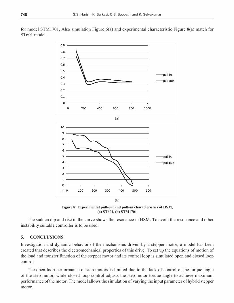
Torque speed characteristics obtained practically for both the model is presented in Figure 8.
It is a practical experience that the pull out curve of a stepper motor suddenly dips to a very low in a particular range of stepping rates as shown in Figure 3. This phenomenon is known as mid-frequency resonance. From Figure 8(a) this can be observed, for ST601. This phenomenon cannot be clearly visuvalised
748 S.S. Harish, K. Barkavi, C.S. Boopathi and K. Selvakumar
for model STM1701. Also simulation Figure 6(a) and experimental characteristic Figure 8(a) match for ST601 model.
(a)
(b)
Figure 8: Experimental pull-out and pull–in characteristics of HSM, (a) ST601, (b) STM1701
The sudden dip and rise in the curve shows the resonance in HSM. To avoid the resonance and other instability suitable controller is to be used.
5. CONCLUSIONSInvestigation and dynamic behavior of the mechanisms driven by a stepper motor, a model has been created that describes the electromechanical properties of this drive. To set up the equations of motion of the load and transfer function of the stepper motor and its control loop is simulated open and closed loop control.
The open-loop performance of step motors is limited due to the lack of control of the torque angle of the step motor, while closed loop control adjusts the step motor torque angle to achieve maximum performance of the motor. The model allows the simulation of varying the input parameter of hybrid stepper motor.

749Modelling and Control of Hybrid Stepper Motor
Figure 9: Dynamic Model of 2 phase HSM (closed loop control)
References1. Kenjo T., “Stepping motors and their microprocessor controls”, oxford university press, Oxford, 1984.2. Athani V. V., “Stepper motors: fundamentals, applications and design, New age international publisher, reprint 2005.3. Amadeu L. Rodrigues, Mario V. Neves, Pedro Sousa, Stanimir Valtchev (2009), POWERENG, pp. 605-610.4. Chiasson. J and Zribi. M (1991), “Position control of a PM stepper motor by exact linearization”, IEEE Trans. Automatic
Control, Vol. 36, pp. 620–625.5. Farshad Khorrami and Prashanth Krishnamurthy (2008), “An analysis of closed-loop commutation delay on stepper motor
control and its application to parameter estimation”, IEEE Trans. Control system technology, Vol. 16, No. 1, pp 70-77.6. H Hebertt Sira-Ramírez (2000), “A passivity plus flatness controller for the permanent magnet stepper motor”, Asian J.
Control, Vol. 9, pp. 1–97. James C. Hung, John Y. Hung and Weibing Gao (1993), “Variable structure control: a survey”, IEEE Trans. Ind. Electron.
Vol. 40, pp. 2–22.8. John N. Chiasson, Marc Bodson, Robert T. Novotnak and Ronald B. Rekowski (1993), “High-performance non linear
feedback control of a permanent magnet stepper motor”, IEEE Trans. Control System Technology, Vol. 1, pp. 5–14.9. Pei An (2002), “PC Interfacing using centronic, RS232 and gaming ports”, Newnes, an imprint of Elsevier Science, pp 150.10. LIYU CAO and HOWARD M. SCHWARTZ (1999), “Oscillation, Instability and Control of Stepper Motors”, Nonlinear
Dynamics 18: pp. 383–404.
