modelling of grounding system placed into vertically
TRANSCRIPT

MODELLING OF GROUNDING SYSTEM PLACED INTO VERTICALLY LAYERED SOIL
ADNAN MUJEZINOVIĆ, NEDIS DAUTBAŠIĆ & IRFAN TURKOVIĆ Faculty of Electrical Engineering, University of Sarajevo, Bosnia and Herzegovina
ABSTRACT The main purpose of the substations grounding systems is to ensure integrity of substations equipment and safety of personnel in and outside of substation at the maximum fault currents. To meet safety requirements, grounding system should have a low as possible resistance. In order to achieve low resistance, grounding systems are designed in a way to achieve as large as possible contact surface between the grounding system conductors and the surrounding soil. On the other hand, cost – efficiency of the proposed solution must be taken into account. Therefore, to meet the technical criteria on the one hand and economic criteria on the other hand, grounding systems are composed from large number of horizontal, vertical and inclined galvanic connected unisolated conductors that in most practical cases form complex geometries. Additionally, soil in which grounding systems are placed is almost always composed of a number of layers with different electric conductivity. In this paper, numerical model based on the indirect boundary element method is presented for calculation of grounding system parameters placed into the vertically layered soil. Keywords: grounding system, vertically layered soil, Fredholm's integral equation of first kind, Green’s functions, Touch voltage, Step voltage.
1 INTRODUCTION Adequate design of substation grounding systems of any voltage level is of crucial importance for the safety of personnel and integrity of the equipment [1]. Safety conditions must be met both at normal operation of the system and during the flow of the highest fault currents. In order to meet the safety requirements, the grounding system with the surrounding soil must provide as low as possible resistance [2]. Low resistance grounding system ensures that the fault current is dissipated to the surrounding soil [3]. Also, geometry of the grounding system must be designed in such a way that during fault current dissipation into the soil, potential difference between the two close points (at a distance of 1 meter [4]) on the earh surface does not exceed the permissible values [5]. In order to achieve the lowest possible grounding resistance, grounding systems are designed in such a way to achieve as large as possible contact surface between the grounding system conductors and the surrounding soil. Therefore, grounding systems are formed from the horizontal, vertical and inclined galvanic connected unisolated conductors that in most cases form very complex geometries. Length and position of the grounding system conductors depends on the available space, substations gear disposition and surrounding soil resistivity [1]. Grounding system parameters that need to be calculated are grounding resistance, touch voltage, step voltage, mesh voltage and electric potential distribution on the soil surface [6]. In order to obtain accurate values of grounding system parameters, soil parameters need to be introduced in the calculation method. In this paper calculation method based on the indirect boundary element method for the grounding system placed into the vertically layered soil is presented.
www.witpress.com, ISSN 1743-3533 (on-line) WIT Transactions on Engineering Sciences, Vol 122, © 2019 WIT Press
doi:10.2495/BE410071
Boundary Elements and other Mesh Reduction Methods XLI 73

2 MATHEMATICAL MODEL Calculation methodology for obtaining the relevant grounding system parameters is based on the calculation of the electric potential distribution in the soil around analysed grounding system when fault current flows. Electric potential distribution in the soil can be calculated by using following set of equations [7]:
0 in Ω, (1)
on Γ, (2)
0 for d , (3)
where φ is electric potential, γ is electric conductivity of soil, Ω is soil, Γ is surface of grounding conductor-surrounding soil interface, d is distance from grounding grid and symbol is Nabla operator. Eqn (1) is a well-known Laplace partial differential equation for static current field, while other two eqns (2) and (3) are imposed boundary conditions. Previous given boundary conditions treat grounding system to soil interface and infinite boundary. For modelling of the surrounding soil additional boundary conditions must be applied. In most practical situation soil is inhomogeneous and can be treated as multi-layered [8]. It can be assumed that multi-layer soil is composed of two or more soil layers of different soil conductivity. At boundary between soil layers, following boundary condition can be applied [9]:
021 JJn
, (4)
where n
is a normal unit vector, 1J
and 2J
is a vector of current density of soil layer 1 and
2, respectively. Same boundary condition can be applied at the boundary soil – air, but since air can be treated as insulator, boundary condition on this interface takes a following form:
01 Jn
, (5)
where 1J
is vector of current density in soil layer 1 which borders with air.
3 INDIRECT BOUNDARY ELEMENT METHOD By applying the well-known Green's identity over the eqn (1), Fredholm's integral equation of the first kind can be obtained, in the following form:
dqpGpJq ,1
, (6)
where p is source point, q is observation point, J is normal component of the surface current density and G(p,q) is Green's function (integral kernel). To solve integral equation by indirect boundary element method double numerical integration must be applied. This can be reduced to one numerical integration by applying
www.witpress.com, ISSN 1743-3533 (on-line) WIT Transactions on Engineering Sciences, Vol 122, © 2019 WIT Press
74 Boundary Elements and other Mesh Reduction Methods XLI
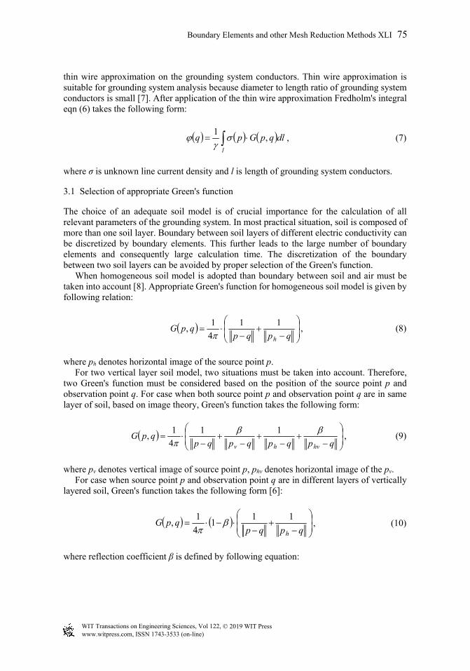
thin wire approximation on the grounding system conductors. Thin wire approximation is suitable for grounding system analysis because diameter to length ratio of grounding system conductors is small [7]. After application of the thin wire approximation Fredholm's integral eqn (6) takes the following form:
l
dlqpGpq ,1
, (7)
where σ is unknown line current density and l is length of grounding system conductors.
3.1 Selection of appropriate Green's function
The choice of an adequate soil model is of crucial importance for the calculation of all relevant parameters of the grounding system. In most practical situation, soil is composed of more than one soil layer. Boundary between soil layers of different electric conductivity can be discretized by boundary elements. This further leads to the large number of boundary elements and consequently large calculation time. The discretization of the boundary between two soil layers can be avoided by proper selection of the Green's function. When homogeneous soil model is adopted than boundary between soil and air must be taken into account [8]. Appropriate Green's function for homogeneous soil model is given by following relation:
qpqpqpG
h
11
4
1,
, (8)
where ph denotes horizontal image of the source point p. For two vertical layer soil model, two situations must be taken into account. Therefore, two Green's function must be considered based on the position of the source point p and observation point q. For case when both source point p and observation point q are in same layer of soil, based on image theory, Green's function takes the following form:
qpqpqpqpqpG
hvhv
11
4
1, , (9)
where pv denotes vertical image of source point p, phv denotes horizontal image of the pv. For case when source point p and observation point q are in different layers of vertically layered soil, Green's function takes the following form [6]:
qpqpqpG
h
111
4
1,
, (10)
where reflection coefficient β is defined by following equation:
www.witpress.com, ISSN 1743-3533 (on-line) WIT Transactions on Engineering Sciences, Vol 122, © 2019 WIT Press
Boundary Elements and other Mesh Reduction Methods XLI 75
21
21
. (11)
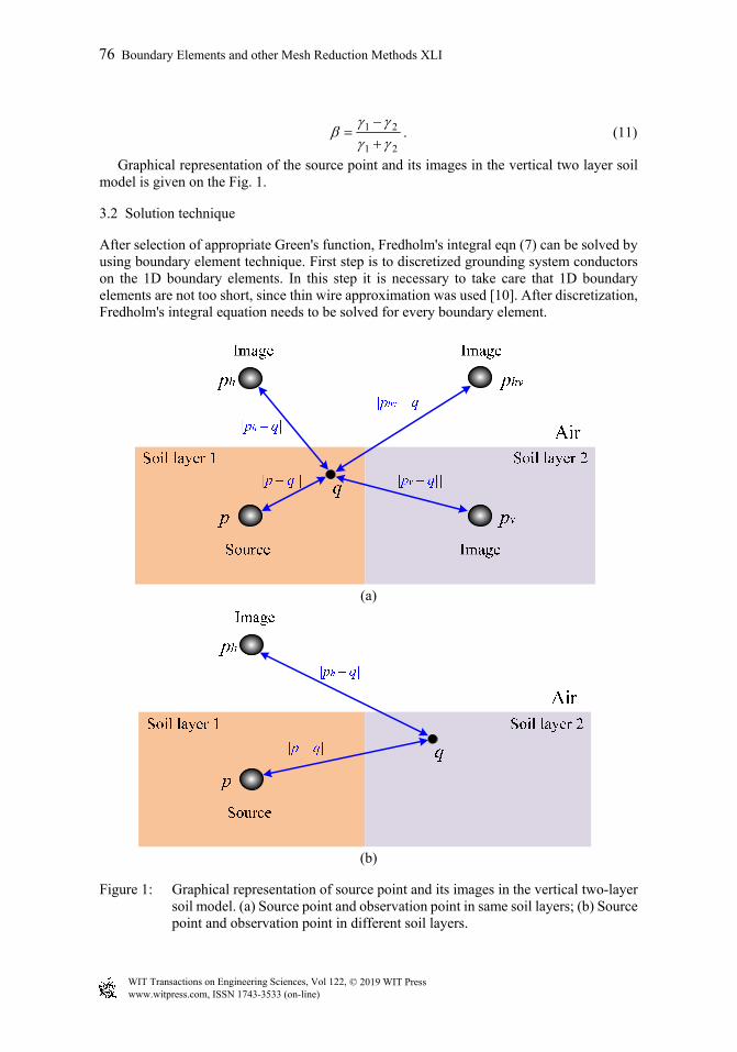
Graphical representation of the source point and its images in the vertical two layer soil model is given on the Fig. 1.
3.2 Solution technique
After selection of appropriate Green's function, Fredholm's integral eqn (7) can be solved by using boundary element technique. First step is to discretized grounding system conductors on the 1D boundary elements. In this step it is necessary to take care that 1D boundary elements are not too short, since thin wire approximation was used [10]. After discretization, Fredholm's integral equation needs to be solved for every boundary element.
(a)
(b)
Figure 1: Graphical representation of source point and its images in the vertical two-layer soil model. (a) Source point and observation point in same soil layers; (b) Source point and observation point in different soil layers.
www.witpress.com, ISSN 1743-3533 (on-line) WIT Transactions on Engineering Sciences, Vol 122, © 2019 WIT Press
76 Boundary Elements and other Mesh Reduction Methods XLI

After discretization of the grounding system conductor its geometry and unknown line current density is approximated with shape functions. In this paper second order polynomial function was used:
nn
ii
ei
e ff1
, (12)
where fe(ξ) is value of function (geometry of line current density) at any point of boundary element, ψi(ξ) is the shape function, fe
i is value of function at i-th point of boundary element and nn is number of collocation points on the boundary element. In order to solve integral equations, it is appropriate to introduce coordinate transformation. After application of the coordinate transformation, Fredholm's integral eqn (7) takes the following form [11]:
en
e
nn
i
ei
ei dJqGq
1
1
1 1
det,1
, (13)
where: ne is number of boundary elements, σi
e is line current density of the e-th boundary element and det J(ξ) is Jacobian determinant. After application of the Gauss-Legendre’s numerical integration on the eqn (13), following matrix equation is obtained [12]:
G , (14)
where [G] is coefficient matrix, {σ} is matrix vector of unknown line current densities and {φ} is matrix of unknown electric potentials. Since in matrix eqn (14) two matrix vectors are unknown, equation cannot be solved in this form. In ordered to solve calculate line current densities and electric potential of grounding system, additional equation must be introduced. The fault current that flows into the grounding system leaks into the surrounding soil. Therefore, mathematical link between the fault current and line current density that leaks from the grounding system to the sounding soil can be given by following equation [1], [11], [12]:
en
e
nn
i
ei
ei
en
e el
eeF ldlI
1 11
, (15)
where: li
e is calculated length in the i-th collocation point of e-th boundary element and IF is the fault current which flows into the grounding system Substituting eqn (15) in eqn (14), following matrix equation can be written [1], [11]–[13]:
www.witpress.com, ISSN 1743-3533 (on-line) WIT Transactions on Engineering Sciences, Vol 122, © 2019 WIT Press
Boundary Elements and other Mesh Reduction Methods XLI 77
FG
cpn
cpn
cpncpncpncpn
cpn
cpn
Illl
GGG
GGG
GGG
0
0
0
0
0
1
.
1
1
2
1
21
21
22221
11211
, (16)
where: φG is electric potential of the grounding system.
3.3 Calculation of touch and step voltage
When designing grounding systems, the two most important parameters needs to be calculated are the touch voltage and the step voltage. Based on these two parameters, it can be assessed whether the safety conditions are met within and around the substation. To calculate touch and step voltage, electric potential on the earth surface must be calculated. Electric potential on the earth surface can be calculated by using Fredholm's integral eqn (7) with observation points q are placed on the earth surface. Since in this stage, current densities of all segments are known, electric potential of all points on the earth surface can be calculated by using following matrix eqn [11]:
eG , (17)
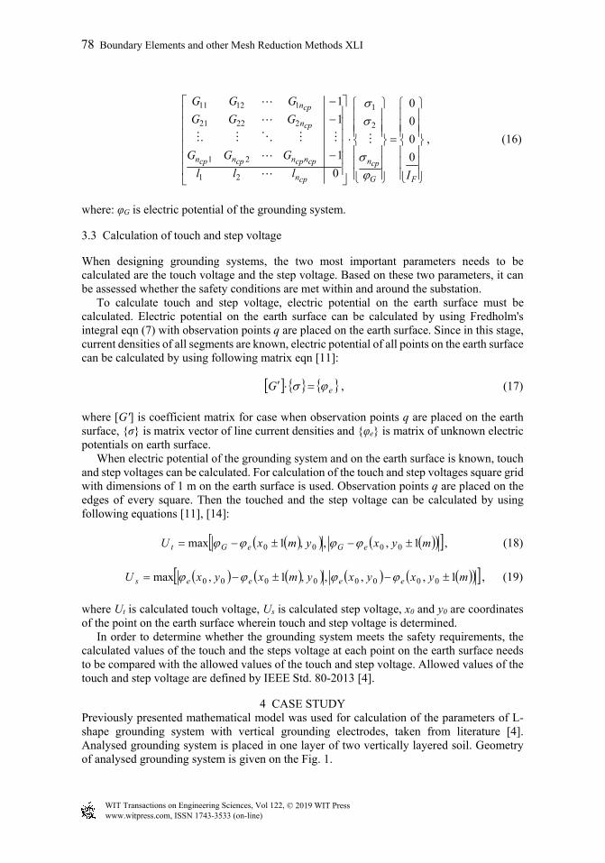
where [G'] is coefficient matrix for case when observation points q are placed on the earth surface, {σ} is matrix vector of line current densities and {φe} is matrix of unknown electric potentials on earth surface. When electric potential of the grounding system and on the earth surface is known, touch and step voltages can be calculated. For calculation of the touch and step voltages square grid with dimensions of 1 m on the earth surface is used. Observation points q are placed on the edges of every square. Then the touched and the step voltage can be calculated by using following equations [11], [14]: myxymxU eGeGt 1,,,1max 0000 , (18)
myxyxymxyxU eeees 1,,,,1,max 00000000 , (19)
where Ut is calculated touch voltage, Us is calculated step voltage, x0 and y0 are coordinates of the point on the earth surface wherein touch and step voltage is determined. In order to determine whether the grounding system meets the safety requirements, the calculated values of the touch and the steps voltage at each point on the earth surface needs to be compared with the allowed values of the touch and step voltage. Allowed values of the touch and step voltage are defined by IEEE Std. 80-2013 [4].
4 CASE STUDY Previously presented mathematical model was used for calculation of the parameters of L-shape grounding system with vertical grounding electrodes, taken from literature [4]. Analysed grounding system is placed in one layer of two vertically layered soil. Geometry of analysed grounding system is given on the Fig. 1.
www.witpress.com, ISSN 1743-3533 (on-line) WIT Transactions on Engineering Sciences, Vol 122, © 2019 WIT Press
78 Boundary Elements and other Mesh Reduction Methods XLI

Figure 2: Geometry of analysed grounding system.
Other parameters relevant for the calculation are given in the Table 1.
Table 1: Input parameters for the calculation.
Parameter Value Fault current IF: 1908 (A) First layer soil conductivity γ1: 0.01 (S/m) Second layer soil conductivity γ2: 0.001 (S/m) The depth of the grounding system h: 1 (m) Length of vertical electrodes le: 7,5 (m) Duration of the fault current t: 0.35 (s) Conductivity of the crush rock on the surface γc: 3.3 10-4 (S/m) Thickness of the crush rock on the surface hc: 0.1 (m) Human body mass m: 70 kg
www.witpress.com, ISSN 1743-3533 (on-line) WIT Transactions on Engineering Sciences, Vol 122, © 2019 WIT Press
Boundary Elements and other Mesh Reduction Methods XLI 79

Results of the electric potential distribution on the earth surface, distribution of the touch and the step voltage are given on the Figs 3, 4 and 5, respectively.
Figure 3: Electric potential distribution on the earth surface.
Figure 4: Distribution of the touch voltage.
-60 -40 -20 0 20 40 60-50
0
50
400
600
800
1000
1200
1400
Length x (m)
Length y (m)
Ele
ctri
c po
tent
ial
(V)
500
600
700
800
900
1000
1100
1200
-60-40
-200
2040
60
-60-40
-200
2040
60
0
500
1000
Length x (m)Length y (m)
Tou
ch v
olta
ge U
t (V
)
100
200
300
400
500
600
700
www.witpress.com, ISSN 1743-3533 (on-line) WIT Transactions on Engineering Sciences, Vol 122, © 2019 WIT Press
80 Boundary Elements and other Mesh Reduction Methods XLI

Figure 5: Distribution of the step voltage.
As it can be noted from results given on the Fig. 3 highest values of the electric potential on the earth surface is directly above the grounding system. Maximum value of the electric potential is 1250.3 V. Highest electric potential gradient is on the edges and outside of the grounding system, while lowest electric potential gradient is directly above grounding system. Also, it can be noted that electric potential gradient is slightly higher in the soil layer with lower electric conductivity. From Fig. 4 it can be noted that values of the touch voltages are lowest on area that is directly above the grounding system and that it increases with increasing distance from the grounding system. Highest values of the step voltage are on the earth surface directly above the edges of the grounding system and on the boundary between two soil layers. It can be noted that value of the step voltage on the boundary between two adjacent soil layers is increased on areas that are closer to the grounding system. On the Figs 6 and 7 changes of the touch and step voltages over the profile line outlined on the Fig. 2 are given. Also maximal allowable values of the touch and step voltages for the body weight of 70 kg and fault clearing time of 0.35 sec.
-50
0
50 -50
0
500
50
100
Length y (m)Length x (m)
Ste
p vo
ltage
Us
(V)
10
20
30
40
50
60
70
www.witpress.com, ISSN 1743-3533 (on-line) WIT Transactions on Engineering Sciences, Vol 122, © 2019 WIT Press
Boundary Elements and other Mesh Reduction Methods XLI 81
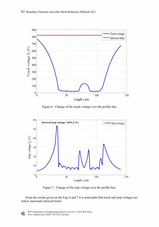
Figure 6: Change of the touch voltage over the profile line.
Figure 7: Change of the step voltage over the profile line.
From the results given on the Figs 6 and 7 it is noticeable that touch and step voltages are below maximum allowed limits.
0 50 100 1500
100
200
300
400
500
600
700
800
900
Length x (m)
Tou
ch v
olta
ge U
t (V
)
Touch voltageAllowed value
0 50 100 1500
10
20
30
40
50
60
Length x (m)
Ste
p vo
ltage
Us (
V)
Step voltageAllowed step voltage: 2691,2 (V)
www.witpress.com, ISSN 1743-3533 (on-line) WIT Transactions on Engineering Sciences, Vol 122, © 2019 WIT Press
82 Boundary Elements and other Mesh Reduction Methods XLI

5 CONCLUSION Grounding system has a key role in ensuring safety of personnel and equipment in the substation and therefore calculation of its parameters requires application of very accurate method. One of the main parameter that can affect computation results is characteristic of the soil in which grounding system is placed. This paper presents mathematical model based on the indirect boundary element method for the calculation of parameters of the grounding system placed into vertically layered soil. In presented mathematical model impact of the soil structure was taken into account with applying adequate Green's functions. Presented mathematical model was used for the calculation of the illustrative grounding system placed in vertically layered soil.
ACKNOWLEDGEMENT This research has been supported by the Ministry of Education and Science of the Federation of Bosnia and Herzegovina.
REFERENCES [1] Mujezinović, A., Software tool for grounding system design. eds. M. Hadžikadić & S.
Avdaković, Advanced Technologies, Systems, and Applications. Lecture Notes in Networks and Systems, Springer: Cham, 3, 2017.
[2] Mujezinović, A., Analysis of discontinuity of electrical conductivity of soil on grounding resistance, MSc. thesis, Faculty of Electrical Engineering, University of Sarajevo: Bosnian, 2011.
[3] Colominas, I., Navarrina, F. & Casteleiro, M., Analysis of transferred earth potentials in grounding systems: A BEM numerical approach. IEEE Transactions on Power Delivery, 20(1), pp. 339–345, 2005. DOI: 10.1109/tpwrd.2004.835035.
[4] IEEE Std. 80—2013, IEEE Guide for Safety in AC Substation Grounding, Dec. 2013. [5] Colominas, I., Navarrina, F. & Casteleiro, M., Numerical simulation of transferred
potentials in earthing grids considering layered soil models. IEEE Transaction on Power Delivery, 22(3), pp. 1514–1522, 2007. DOI: 10.1109/tpwrd.2007.899282.
[6] He, J., Zeng, R. & Zhang, B., Methodology and Technology for Power System Grounding, John Wiley & Sons: Singapore, 2013.
[7] Colominas, I., Navarrina, F. & Casteleiro, M., A numerical formulation for grounding analysis in stratified soils. IEEE Transactions on Power Delivery, 17(2), pp. 587–595, 2002. DOI: 10.1109/61.997943.
[8] Barić, T., Boras, V. & Nikolovski, S., Analysing the effect of discontinuity of electrical conductivity of soil on ground resistance. Journal of Energy, 55(4), pp. 454–473, 2006.
[9] Mujezinović, A., Muharemović, A., Muharemović, A., Turković, I. & Bajramović, Z., Application of finite element method in calculation of large and complex grounding systems. International Conference and Exposition on Electrical and Power Engineering (EPE), pp. 688–692, Romania, Iasi, Oct. 2012.
[10] Navarrina, F., Colominas, I. & Casteleiro, M., Why do computer methods for grounding analysis produce anomalous results? IEEE Transaction on Power Delivery, 18(4), pp. 1192–1202, 2003. DOI: 10.1109/tpwrd.2003.817499.
[11] Mujezinović, A., Mulaosmanović, A., Muharemović, A., Turković, I. & Bajramović, Z., A combined boundary element and an analytical approach to grounding mesh modeling in a multi-layer soil. Elektrotehniški Vestnik 84(1–2), pp. 39–47, 2017.
[12] Zildzo, H., Muharemović, A., Turković, I. & Matoruga, H., Numerical Calculation of Floating Potentials for Large Earthing Systems. XXII International Symposium on Information, Communication and Automation Technologies: Sarajevo, Oct. 2009.
www.witpress.com, ISSN 1743-3533 (on-line) WIT Transactions on Engineering Sciences, Vol 122, © 2019 WIT Press
Boundary Elements and other Mesh Reduction Methods XLI 83
[13] Freschi, F., Mitolo, M. & Tartaglia, M., Interferences phenomena between separate grounding systems, industry applications society annual meeting. IEEE, 2013.
[14] Poljak, D., The Theory of Electromagnetic Fields with Applications in Engineering, Školska knjiga: Zagreb, 2014.
www.witpress.com, ISSN 1743-3533 (on-line) WIT Transactions on Engineering Sciences, Vol 122, © 2019 WIT Press
84 Boundary Elements and other Mesh Reduction Methods XLI