modulation formats for digital fiber transmission eric tell 050329
Post on 19-Dec-2015
222 views
TRANSCRIPT

Modulation formats for digital fiber transmission
Eric Tell 050329

Outline• Fiber performance limitations• WDM• Optical vs. radio communication• Optical modulators• Modulation formats
– Amplitude shift keying
– Duo-binary signalling
– Optical single sideband signalling
• Simulation/experimental results• Summary
Fiber performance limitations
• Fiber Loss
• Chromatic dispersion– different refractive index for different
wavelengths
• Fiber non-linearities

Chromatic dispersion
• Distance limit ~1/(bit rate)²– Example: Single mode fiber @1550nm
• chromatic dispersion: 17ps/km-nm
• dispersion limited distance: ~100km @10Gbit/s
• comparable to loss limit
• EDFA => increased loss-limited distance– Chromatic dispersion becomes the limiting factor in
single mode long-haul fibers!
• We want to decrease the bandwidth for a given datarate!
Wave Division Multiplexing
• Decreased channel spacing leads to interchannel interference and makes it difficult to compensate for fiber nonlinearities
• Narrower subchannels would be nice...
WDM (cont'd)
• In a high capacity link the whole EDFA spectrum is filled with subchannels
• The bandwidth of each subchannel is proportional to its bit rate
• Total fiber capacity is given by the spectral efficency: (bitrate per channel)/(channel spacing)
WDM (cont'd)
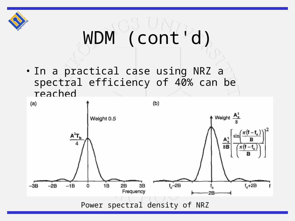
• In a practical case using NRZ a spectral efficiency of 40% can be reached
Power spectral density of NRZ
WDM (cont'd
• More GB/s per channel does not increase total bandwith, however– It results in fewer channels to manage– Increased channel spacing decreases
some non-linear distortions• BUT to reach higher spectral efficiency a
format with narrower spectrum for a given bandwidth is needed (while at the same time not increasing other impairments)
How can this be achieved?
• M-ary Amplitude Shift Keying (ASK)
• Duo-binary signaling• Optical Single Sideband (OSSB)
Comparison to radio systems
• Much of the same theory can be applied, except– Carrier frequency is different
• 1550 nm => 194 Thz
– The available components are different• no coherent detection (no PLLs)
– The channel is different
Component imperfections
• Modulators are nonlinear– difficult to achieve pure AM
• PIN photo detectors responds to optical power rather than electrical field amplitude (“square envelope”)
• Dispersion introduces a frequency dependent phase shift
• “intensity-modulated” approaches are used
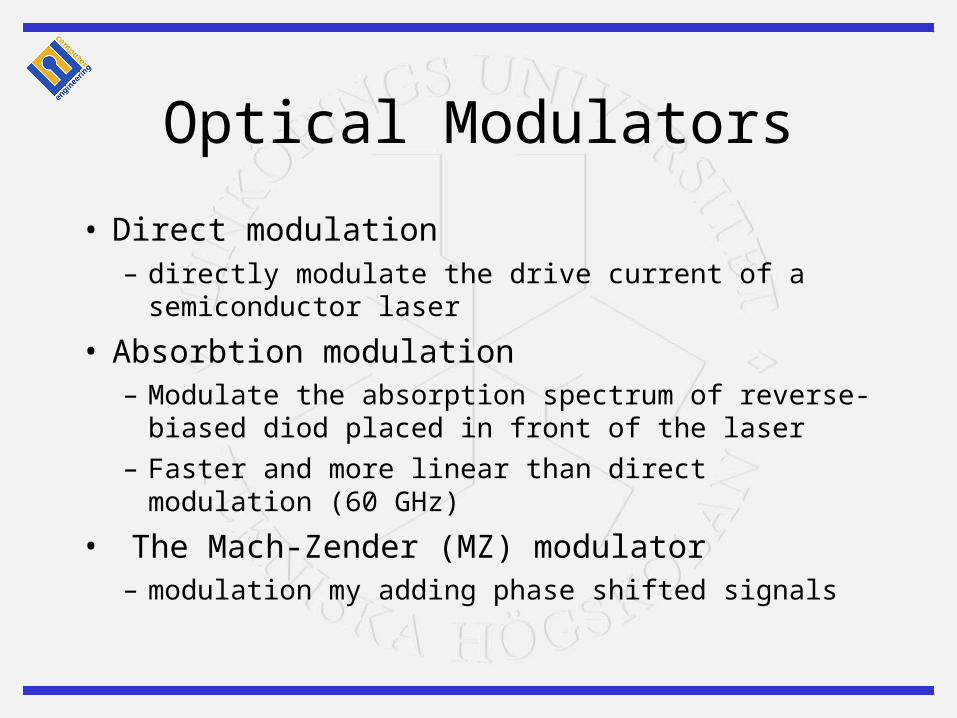
Optical Modulators
• Direct modulation– directly modulate the drive current of a semiconductor
laser
• Absorbtion modulation– Modulate the absorption spectrum of reverse-biased
diod placed in front of the laser
– Faster and more linear than direct modulation (60 GHz)
• The Mach-Zender (MZ) modulator– modulation my adding phase shifted signals
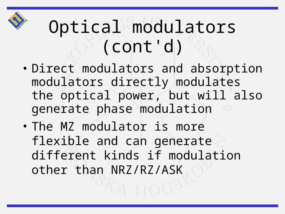
Optical modulators (cont'd)
• Direct modulators and absorption modulators directly modulates the optical power, but will also generate phase modulation
• The MZ modulator is more flexible and can generate different kinds if modulation other than NRZ/RZ/ASK
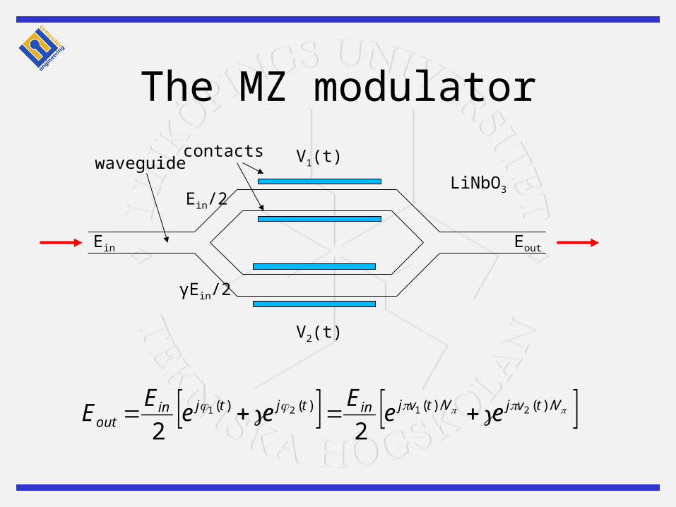
The MZ modulator
V1(t)
V2(t)
Ein
Ein/2
γEin/2
Eout
LiNbO3
waveguidecontacts
VtvjVtvjintjtjinout ee
Eee
EE /)(/)()()( 2121
22
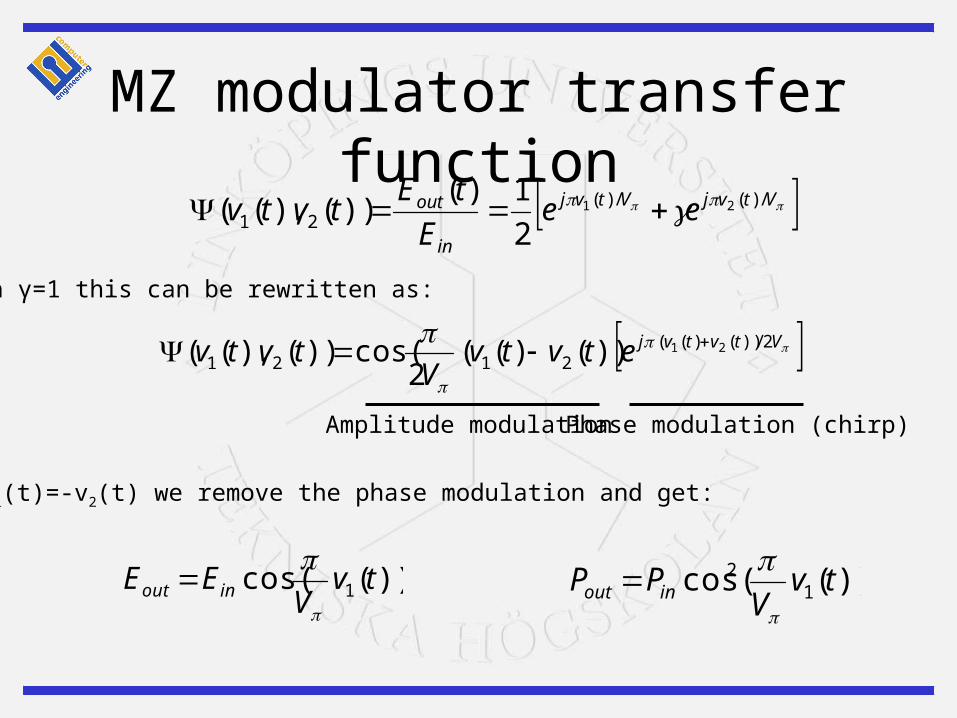
MZ modulator transfer function VtvjVtvj
in
out eeE
tEtvtv /)(/)(
2121
2
1)())(),((
VtvtvjetvtvV
tvtv 2/))()((2121
21))()((2
cos())(),((
))(cos( 1 tvV
EE inout
With γ=1 this can be rewritten as:
Amplitude modulation Phase modulation (chirp)
With v1(t)=-v2(t) we remove the phase modulation and get:
))((cos 12 tv
VPP inout
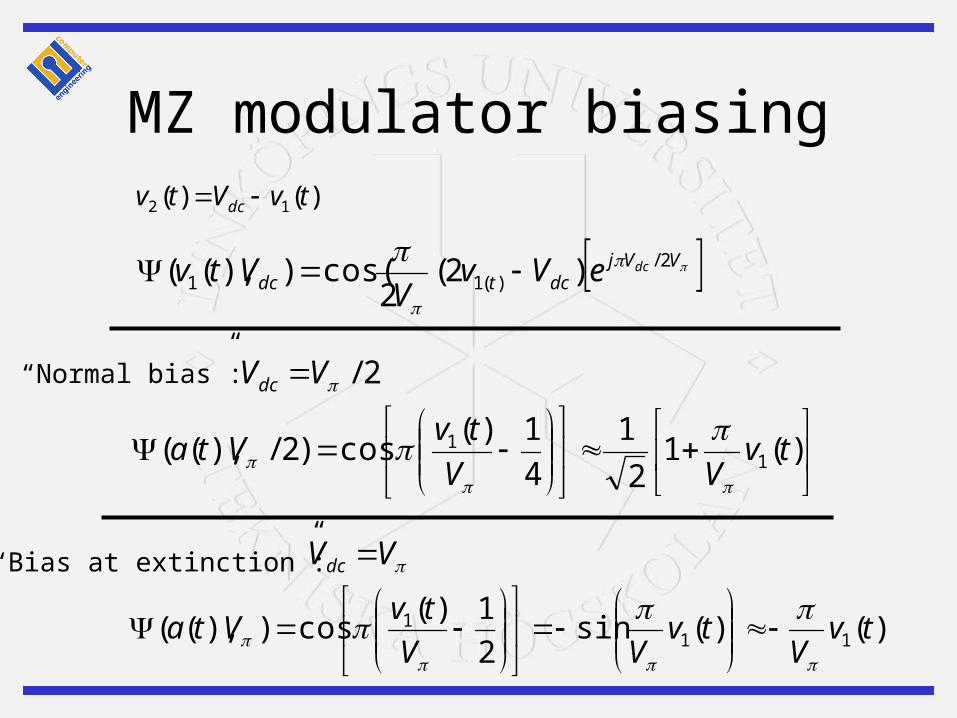
MZ modulator biasing)()( 12 tvVtv dc
VVjdctdc
dceVvV
Vtv 2/)(11 )2(
2cos()),((
2/VVdc
VVdc
)(1
2
1
4
1)(cos)2/),(( 1
1 tvVV
tvVta
)()(sin2
1)(cos)),(( 11
1 tvV
tvVV
tvVta
“Normal bias”:
“Bias at extinction”:

MZ modulators - observations
• These modulators are only linear in a small region– A problem for other than RZ/NRZ signaling
• There must normally be an unmodulated carrier in order to use non-coherent detection

M-ASK• Less bandwidth
• More power needed for a given BER• non-linearities become limiting in
long-haul DWDM systems• More complicated (analog and
digital) electrical circuits• Possibly useful in multi-mode
dispersion limited systems e.g. 10 Gbit/s Ethernet
levels
bandwidth
2 ±B
4 ±B/2
8 ±B/3
16 ±B/4
32 ±B/5
64 ±B/6

Duo-binary signaling
• Introduce correlation between consecutive symbols
• A special case of partial response signaling:

Duo-binary signaling
• Add consecutive symbols => three signal levels
-1,1,1,-1
-2,0,2,0MZ modulator

AM-PSK Duo-binary
• Problem: Normally impractical to handle three levels
• Solution: Use 0,E,-E– The detector will detect two levels 0 and E²– By precoding these two levels will correspond to
0 and 1– a.k.a Amplitude Modulated Phase Shift Keying
(AM-PSK) duo-binary signaling
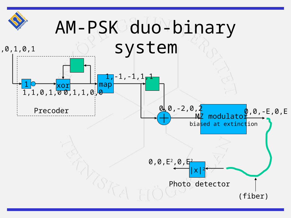
AM-PSK duo-binary system
1,1,0,1,0
MZ modulator biased at extinction
xor map
|x|2
0,1,1,0,0
1,-1,-1,1,1
0,0,-2,0,2 0,0,-E,0,E
1
0,0,1,0,1
0,0,E2,0,E2
(fiber)
Photo detector
Precoder
Optical Single Sideband (OSSB)
• Observation: The frequency spectrum is symmetrical
• Implication: Half of it can be filtered out to save bandwidth => Single Sideband Transmission!
• Used e.g. in TV
Subcarrier OSSB
• In conventional subcarrier modulation the subcarrier appears on both sides of the optical carrier
• Dispersion causes a phase shift between the two signals, which depends on the distance
• At certain points the entire signal is canceled out!
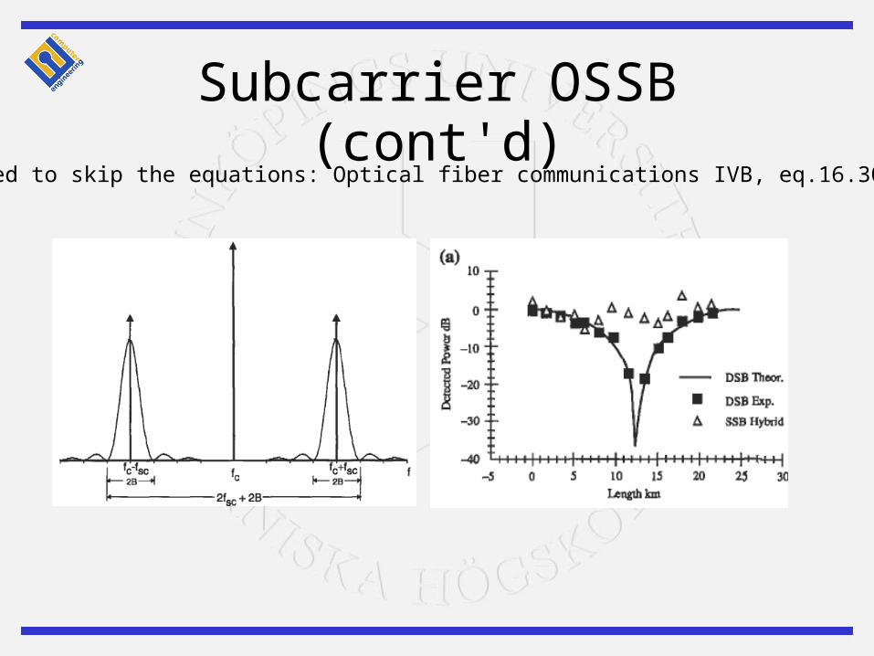
Subcarrier OSSB (cont'd)(decided to skip the equations: Optical fiber communications IVB, eq.16.30-16.36)
Creating an SSB signal
• Two ways– Use a filter (half the energy is lost)– Use the Hilbert transform
• known as a Hartley modulator
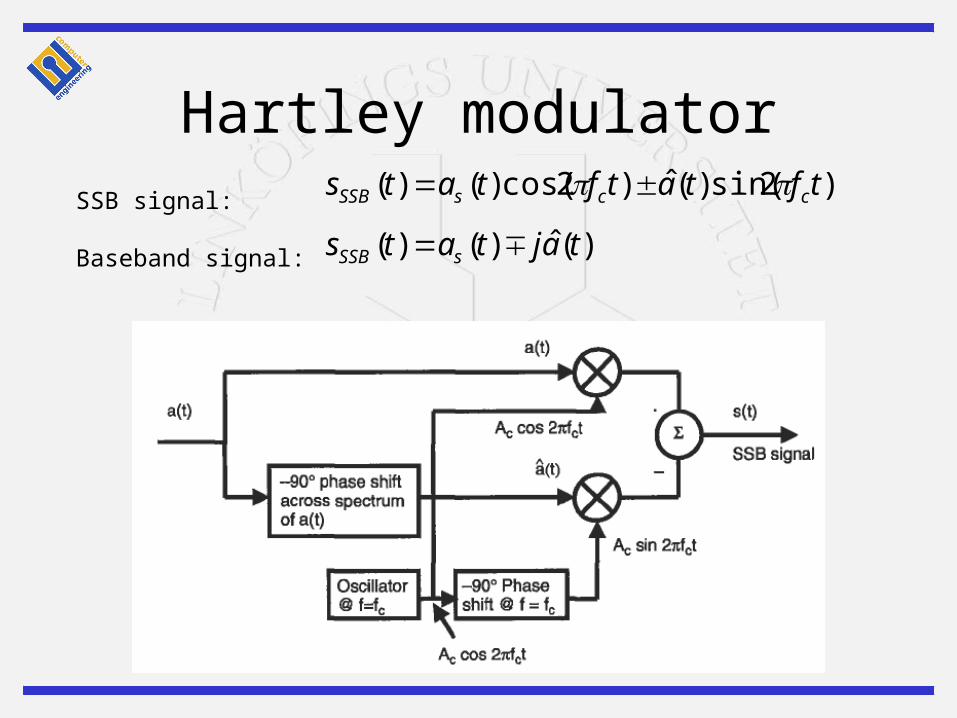
Hartley modulator)2sin()(ˆ)2cos()()( tftatftats ccsSSB
)(ˆ)()( tajtats sSSB SSB signal:
Baseband signal:

Optical SSB modulator)(ˆ)()( tajetatg “Approximation” of SSB signal:
MZAmplitudemodulator
Hilberttransform
Phasemodulator
a(t)
Optical carrier
â(t)
OSSB signal
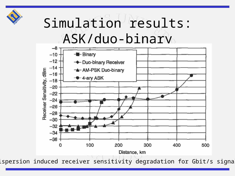
Simulation results: ASK/duo-binary
Dispersion induced receiver sensitivity degradation for Gbit/s signalling

More practical issues…
• ASK– Nees more power =>
non-linearities limiting• Duo-binary
– Needs extra filtering– Optical dispersion
compensation could be an alternative
– 225 km @10Gbit/s 1550 nm has been reached
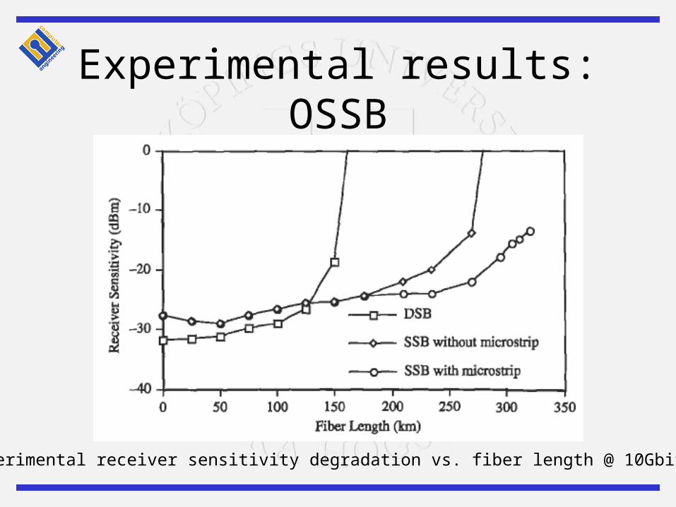
Experimental results: OSSB
Experimental receiver sensitivity degradation vs. fiber length @ 10Gbit/s, BER=10 -9
DWDM
• “Normal” NRZ– 40% spectral efficiency over 150 km
• Duo-binary AM-PSK– 100% over 100 km
• OSSB– 66% over 300 km
Summary
• Distance between repeaters is limited by either of– Fiber loss– Chromatic dispersion– Fiber non-linearities
• With the advent of EDFA chromatic dispersion has become the limiting factor in long-haul systems
Summary (cont’d)
• We want to limit the bandwidth in order too– Reduce the effects of chromatic dispersion
– Reach higher spectral efficiency in DWDM systems
• Two potential methods:– Duo-binary signaling
– Optical single sideband
• Both methods could potentially halve the bandwidth• None of the methods are currently used in commercial
systems, but there are some promising experimental results