modulation techniques for three-phase four-leg inverters
TRANSCRIPT

Modulation Techniques for Three-Phase Four-Leg Inverters
ARMANDO BELLINI and STEFANO BIFARETTIDepartment of Electronic Engineering
University of Rome “Tor Vergata”Via del Politecnico 1, 00133 Rome
ITALY
Abstract: - Three-phase four-leg inverters are typically employed to supply unbalanced loads avoiding the useof a transformer. Usually, the inverter control is performed by modulation techniques, such as the three-dimensional one, requiring complex mathematical algorithms. The paper suggests a different approach, basedon the separation of the control of the fourth leg from that of the other phases, allowing the application to thethree inverter phases of traditional SVM techniques and avoiding the employment of complex procedures.
Key-Words: - Converters, Modulation, Power Generation, Uninterruptible Power Supplies.
1 IntroductionMany power electronics applications, such asDistributed Generation Systems, UninterruptiblePower Supplies or active filtering, employ aninverter feeding a star connected three-phase loadwith accessible neutral terminal. The currentsflowing on each phase are generally not balancedso, if a transformer is not required, a connection tothe neutral terminal should be provided by addingan extra wire to the inverter.
The load neutral terminal can be connected tothe inverter using two different topologies:
• three-phase four-wire, in which the neutralpoint is connected directly to the midpoint of thesupply by means of a capacitor divider;
• three-phase four-leg, employing an additionalinverter leg that permits to modify the neutral pointvoltage.
The first solution, shown in Fig. 1, is certainlythe simplest one, but the three-phase inverter turnsinto three independent single-phase inverters. Asconsequence, zero-sequence harmonics aregenerated; moreover, specially when the load isunbalanced or non-linear, a high voltage ripple oversupply capacitors is produced by neutral currents. Afurther limitation is represented by the maximumvoltage value that the amplitude of each phasefundamental harmonic can reach.
The second solution, shown in Fig. 2, requirestwo additional power switches and a more complexcontrol strategy, but it offers different advantages,such as an increased maximum output voltage value,a reduction of neutral currents and the possibility ofneutral point voltage control.
Fig.1 - Three-phase four-wire inverter.
Fig.2 - Three-phase four-leg inverter.
Different Pulse Width Modulation techniques forthree-phase four-leg inverters were proposed inliterature. The most popular techniques are denotedas three-dimensional Space Vector Modulation(SVM) and can be applied to two-level [1-2], orthree-level inverters [3-5]. These techniques arebased on the assumption that the fourth legintroduces additional switching combinations and,then, an increased number of space vectors, ifcompared with traditional three-leg inverters. Toselect, in each sampling interval, the space vector
Proceedings of the 6th WSEAS International Conference on Power Systems, Lisbon, Portugal, September 22-24, 2006 398

nearest to the desired voltage vector, generallycomplex mathematical algorithms, based on threedimensional geometrical figures, are employed.
In order to simplify the control of four-leginverters, a previous paper [6] proposed a differentapproach based on the separation of the control ofthe fourth leg from that of the other phases, allowingthe application to the three inverter phases oftraditional SVM techniques and avoiding theemployment of complex procedures. This papercontinues the previous study taking into accountuniform sampling modulation techniques and adifferent topology of the fourth leg.
To make more intelligible the waveforms of thevoltages and currents, a quite low value of themodulation frequency has been selected; inparticular, it has been assumed that the fundamentalharmonic of the voltages applied to the load has afrequency fr equal to 50 Hz and that frequency fc ofthe carrier is equal to 750 Hz, i.e. ratio k betweenthe carrier and the reference frequencies is equal to15. However, the results obtained by the differentsolutions were validated using a rather bigger valueof ratio k. Besides, it has been supposed that supplyvoltage Vdc is equal to 800V and that the threephases of the load must be supplied with a RMSvoltage value equal to 220 V.
The waveforms and the connected harmoniccontents were obtained by simulation, using theSimulink-SimPowerSystems tools, taking intoaccount both the real behaviour of the invertercomponents and the dead times necessary for thecommutations.
2 Modulation TechniquesAs said in the introduction, the paper propose toemploy, for the three inverter phases (a, b and c), astandard modulation technique. To this aim, thetriangle intersection technique based PWM,employing the zero sequence injection principle,described in [7] is taken into consideration. Asshown in the Simulink block diagram of Fig. 3, thistechnique determines modulated signals vma, vmb andvmc , that produce the inverter phases commutations,by comparing a symmetric triangular carrier vc withthree reference voltages, vra, vrb and vrc, obtained byadding, to three sinusoidal reference voltages, asuitable zero sequence signal v0. In this paper thetechnique denoted in [7] as SVPWM, applying thezero sequence signal depicted in Fig. 4, is used. Themodulation produced by the comparison betweeneach reference signal (vra, vrb and vrc) and the carriersignal can be produced employing either a naturalsampling of the reference signals or a uniformsampling.
Fig. 3 - Triangle intersection technique blockdiagram.
0 0.005 0.01 0.015 0.02
-0.2
-0.1
0
0.1
0.2
0.3
time (s)
zero
sequ
ence
sign
al
Fig. 4 Waveform of voltage v0.
When the control of the inverter is performed bya microprocessor based board, the sampling iscertainly of uniform type. Therefore in this paper auniform sampling has been preferred; besidessampling period Ts has been selected equal to anhalf period of the carrier: Ts=1/2fc, so that thesampling instants coincide with those in which thecarrier assumes the maximum and minimum values.
Taking into consideration an intervalcharacterized by a negative slope of the carrier, thecomparisons of the reference signals with the carriersubdivide the sampling interval in four subintervals,whose lengths are denoted as to, t1, t2 and t3, asshown in Fig 5.
Fig. 5 - Subdivision of the sampling interval.
Employing the zero sequence signal depicted inFig. 4, length to is equal to t3; so in each samplinginterval only lengths t1 and t2 and the sequence of
Proceedings of the 6th WSEAS International Conference on Power Systems, Lisbon, Portugal, September 22-24, 2006 399

the commutations must be determined. Similarshapes occur in the sampling intervals in which thecarrier has a positive slope.
In three-leg inverters with balanced load, voltagevn, applied to the load neutral point and referred tothe midpoint of the supply voltage, is, at everyinstant, equal to the mean value of the three outputvoltages va, vb and vc. Therefore, as shown in Fig 6,its waveform depends only on lengths t1 and t2. It ispossible to observe that the mean value of voltage vn
during the sampling interval is equal to 2 1
6dcs
t tV
T
and it is proportional to the value assumed by zerosequence signal v0, sampled at the beginning of thesampling period.
The waveform of voltage vn, illustrated in Fig. 7,is characterized by a period equal to the third part ofthat of the output voltages; so only harmonics atfrequencies multiple of 3fr are present.
When the load is balanced, the waveform ofeach phase voltage has a very good harmoniccontent because all the harmonics of order multipleof three, which appear in the phase output terminalvoltages, appear also in the load neutral pointvoltage and practically disappear in phase voltages;so the waveforms of the load neutral point voltage,illustrated in Figs. 6 and 7, can be considered as theideal neutral point voltage shapes. Table 1 showsthe amplitudes of the first harmonics of a phasevoltage, referred to the fundamental one. Takinginto account all the harmonics up to the frequencyof 1 kHz, the Total Harmonic Distortion (THD%) isequal to 30.10.
When the load is unbalanced, the sum of theinstantaneous values of the three phase currentsassumes values different from zero; thus, it isnecessary to connect the load neutral point to theinverter.
Fig. 6 - Shape of voltage vn in a sampling period.
0 0.002 0.004 0.006 0.008 0.01-400
-200
0
200
400
time (s)
load
neut
ralp
oint
volta
ge(V
)
Fig. 7 - Waveform of the load neutral point voltage.
Harmonic order Amplitude %3 0.075 1.597 4.279 0.12
11 11.5513 19.5815 0.0617 14.3619 7.35
Table 1 – Harmonics of a SVPWM phase voltage.
The harmonic content of a phase voltagefurnished by a four-wire structure coincides withthat of a phase output terminal voltage. Therefore,its waveform has an unacceptable harmonic content,as can be deduced by the amplitude of theharmonics, listed in Table 2 and by a value ofTHD% equal to 110.29.
The employment of the Sinusoidal Pulse WidthModulation (SPWM) technique allows improvingthe harmonic content, avoiding the use of the zerosequence signal.
Harmonic order Amplitude %3 20.515 0.747 0.389 2.47
11 8.8213 14.5615 104.6717 17.7619 13.28
Table 2 - Harmonics of a phase voltage; four-wire structure.
As shown by Table 3, this technique reduces theamplitudes of the first harmonics (specially that ofthe third harmonic) but those of the thirteenth,
Proceedings of the 6th WSEAS International Conference on Power Systems, Lisbon, Portugal, September 22-24, 2006 400

fifteenth and seventeenth and the value of THD%(equal to 114.31%) slightly increase; besides, theamplitude of the fundamental harmonic of eachphase voltage cannot become greater than / 2dcV ,while the SVPWM allows a maximum value equalto / 3dcV .
Harmonic order Amplitude %3 0.385 0.117 0.099 0.10
11 0.3913 24.0915 107.7917 29.4219 1.72
Table 3 - Harmonics of a SPWM phase voltage.
To increase the maximum voltage value, it isnecessary to employ the four-leg inverter structureshown in Fig. 2, which requires two additionalpower switches (Sn1 and Sn2); by this way outputvoltages va, vb and vc can be obtained by theSVPWM technique, while the shape of voltage vn,applied to the load neutral point, must be selected soto reduce the phase voltage harmonics.
3 Choice of the Neutral Point VoltageThe model of the three-phase four-leg inverter andits modulation system was implemented in Matlab-Simulink environment. Fig. 8 illustrates thestructure of the conversion circuit.
A first way to select the neutral point voltagewaveform is to use, for the fourth leg modulation,the same carrier employed for the other legs andvoltage v0 as reference. The structure of the wholemodulation system is depicted in Fig. 9.Fig. 10 represents the voltage vn waveform, referredto the midpoint of the supply voltage, during thesampling period examined in Fig 5. Voltage vn
assumes only two values (- / 2dcV and + / 2dcV )whose durations are respectively equal to:
0 1 2
0 1 2
(2 ) / 3
( 2 ) / 3 .s
t t t t
t t t t T t
(1)
The obtained neutral point voltage has the samemean value as the ideal neutral point voltageillustrated in Fig. 6, but its shape is rather different;therefore, the harmonics of order multiple of threeare only partially reduced.
Applying the described voltage waveform, aTHD% equal to 63.12 and the harmonic contentshown in Table 4 is produced by a phase voltage.Table 4 highlights a significant reduction of thevoltage distortion versus the four-wire solution.
Harmonic order Amplitude %3 0.215 0.817 0.529 0.1411 8.7813 14.6715 56.5217 17.8219 13.34
Table 4 - Harmonics of the four-leg phase voltage.
Fig.8. - Simulink model of the three-phase four-leg inverter circuit.
Proceedings of the 6th WSEAS International Conference on Power Systems, Lisbon, Portugal, September 22-24, 2006 401
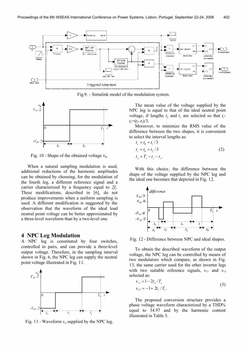
Fig.9. - Simulink model of the modulation system.
Fig. 10 - Shape of the obtained voltage vn.
When a natural sampling modulation is used,additional reductions of the harmonic amplitudescan be obtained by choosing, for the modulation ofthe fourth leg, a different reference signal and acarrier characterized by a frequency equal to 2fc.These modifications, described in [6], do notproduce improvements when a uniform sampling isused. A different modification is suggested by theobservation that the waveform of the ideal loadneutral point voltage can be better approximated bya three-level waveform than by a two-level one.
4 NPC Leg ModulationA NPC leg is constituted by four switches,controlled in pairs, and can provide a three-leveloutput voltage. Therefore, in the sampling intervalshown in Fig. 6, the NPC leg can supply the neutralpoint voltage illustrated in Fig. 11.
Fig. 11 - Waveform vn supplied by the NPC leg.
The mean value of the voltage supplied by theNPC leg is equal to that of the ideal neutral pointvoltage, if lengths tx and tz are selected so that tz-tx=(t2-t1)/3.
Moreover, to minimize the RMS value of thedifference between the two shapes, it is convenientto select the interval lengths as:
0 1
0 2
/ 3
/ 3
.
x
z
y s x z
t t t
t t t
t T t t
(2)
With this choice, the difference between theshape of the voltage supplied by the NPC leg andthe ideal one becomes that depicted in Fig. 12.
Fig. 12 - Difference between NPC and ideal shapes.
To obtain the described waveform of the outputvoltage, the NPC leg can be controlled by means oftwo modulators which compare, as shown in Fig.13, the same carrier used for the other inverter legswith two suitable reference signals, vr1 and vr2
selected as:
1
2
1 2 /
1 2 / .r x s
r z s
v t T
v t T
(3)
The proposed conversion structure provides aphase voltage waveform characterized by a THD%equal to 34.97 and by the harmonic contentillustrated in Table 5.
Proceedings of the 6th WSEAS International Conference on Power Systems, Lisbon, Portugal, September 22-24, 2006 402

Ts t
v1
-1
0
vc
vr1
vr2
tx ty tz
Fig. 13 - Modulation of the NPC leg.
Harmonic order Amplitude %3 0.745 0.867 0.529 1.2711 8.7413 14.6915 20.6617 17.9819 13.31
Table 5 - Harmonics of the four-leg phase voltage.
Comparing Table 5 with Tables 1 and 4, it can beobserved that, adopting the proposed conversionstructure, the phase voltages imposed by the four-leg inverter are characterized by a fully acceptableharmonic content.
5 ConclusionThe paper set its focus on three-phase four-leginverters used to supply unbalanced loads withoutusing a transformer.
Three different converter structures wereconsidered, analyzing their performance by usingsuitable models implemented in Matlab-Simulinkenvironment: three-phase four-wire, in which the load neutral
point is connected directly to the midpoint of thesupply voltage by means of a capacitor divider;
three-phase four-leg, employing an additionaltwo-level inverter leg;
three-phase four-leg, employing an additionalthree-level NPC inverter leg.
The first conversion structure supplies an outputvoltage characterized by an unacceptable harmoniccontent; so a three-phase four-leg inverter must beused. The second conversion structure, suitablycontrolled, gives rise to an acceptable harmoniccontent, whilst a significant improvement isobtained using the third solution, even if the
conversion structure, using a NPC fourth leg, ismore complex.
The proposed approach can be applied also tofour-leg Neutral Point Clamped (NPC) inverters,which employ four switches on each leg. For themodulation of NPC inverters, particularly employedin high-power applications, efficient SVMtechniques, investigated also by authors in severalpapers [8-9], should be applied.
References:[1] R. Zhang, D. Boroyevich and V. H. Prasad “AThree-Phase Inverter with a Neutral Leg with SpaceVector Modulation”, Applied Power ElectronicsConference and Exposition, 1997, pp.857-863,February 1997.[2] R. Zhang, V. H. Prasad, D. Boroyevich and F. C.Lee, “Three-Dimentional Space Vector Modulationfor Four-Leg Voltage-Source Converters”, IEEETrans. on Power Electronics , 17(3), pp.314 -326,May 2002.[3] Man. Wong, J. Tang and Y. Han, “Three-Dimensional Pulse-Width Modulation Technique inThree-level Power Inverters for Three-Phase Four-Wired System”, IEEE Trans. on Power Electronics,16(3), pp.418 -427, May 2001.[4] Man. Wong, J. Tang and Y. Han, “CylindricalCoordinate Control of Three-Dimensional PWMTechnique in Three-Phase Four-Wire TrilevelInverter”, IEEE Trans. on Power Electronics, 18(1),pp.208 -220, January 2003.[5] J. Yao and T. C. Greeng, “Three-DimensionalSpace Vector Modulation for a Four-Leg Three-Level Inverter”, 11th European Conference onPower Electronics and Applications, EPE2005,September 2005.[6] A. Bellini and S. Bifaretti, “A Simple ControlTecnique for Three-Phase Four-Leg Inverters”, Int.Symposium on Power Electronics, Electrical Drives,Automation and Motion, SPEEDAM206, May 2006,To appear.[7] A. M. Hava, R. J. Kerkman and T. A. Lipo,“Simple Analytical and Graphical Tools for CarrierBased PWM Methods”. Proc. of 28th Annual IEEEPower Electronics Specialists Conference, PESC'97, June 1997.[8] A. Bellini and S. Bifaretti, “Comparisonbetween Sinusoidal PWM and Space VectorModulation Techniques for NPC Inverters”, 2005IEEE St. Petersburg PowerTech, June 2005.[9] A. Bellini and S. Bifaretti, “A New Strategy forSpace Vector Modulated NPC Inverters”, WSEASTrans. on Circuits and Systems, Vol. 4, Issue 7, July2005.
Proceedings of the 6th WSEAS International Conference on Power Systems, Lisbon, Portugal, September 22-24, 2006 403