module 4 design for assembly -...
TRANSCRIPT

Module 4
Design for Assembly

Lecture 1
Review of Assembly Processes
Instructional Objective This lecture module intends to train the students on different types of assembly processes and
how the same influence part design.
Why Design for Assembly? Design for Assembly is an exercise to facilitate ease of assembly when manufacturing a
component with multiple parts. Obviously, the reduction in the total number of parts for an
assembly has the added benefit of reducing the total cost of parts in the assembly. Design for
Assembly should ideally be considered at various stages during the selection of material,
shape and processes so that the overall manufacturability and assembly of the component are
facilitated.
Assembly Processes and Guidelines The assembly processes involve the proper placement and appropriate integration of more
than one parts to manufacture a final component. The assembly processes can be broadly
classified into three classes: Adhesives, Fasteners and Welding. These classes can be further
divided into several sub-classes.
Fasteners Rivets
The major virtue of rivets is the strength and performance of the joints. The riveted joints are
simple to design, easy to assemble and economical. Following are some design rules to be
followed for riveted joints.
1. Provide sufficient clearance around rivet locations to allow room for a standard
riveting gun and avoid marring or damaging of the workpiece contact surface with the
rivets [Figure 4.1.1(a)].
2. Use eyelets and tubular rivets whenever they provide sufficient load bearing
application for the intended application. Tubular and semi-tubular rivets, and eyelets
require much lower clinching forces and can be hopper-fed, inserted, and set
automatically on inexpensive equipment.
3. When riveting thick materials, buckling of rivets can be avoided by counter boring the
rivet holes [Figure 4.1.1(b)].
4. Rivet holes should not be too close or too far from the edges of the parts being joined
[Figure 4.1.1(c)].
5. Rivets should be of appropriate length to avoid incorrect clinching [Figure 4.1.1(d)]. 6. When joining pieces of different thickness, it is preferable to upset the rivet against
the thicker and stronger material [Figure 4.1.1(e)].
7. When joining soft or fragile materials with rivets, it is desirable to use metal washers
to distribute the force of upsetting and prevent damage to the parts [Figure 4.1.1(f)].

Fig no Not Recommended Recommended
(a)
(b)
(c)
(d)
(e)
(f)
Figure 4.1.1 Guideline for riveted assemblies [1]
Screw Fasteners
Threaded fasteners include screws, bolts, and machine screws and are widely used to secure
parts together. Some of the significant design guidelines are listed below when threaded
fasteners are in use for an assembly.
1. When strong holding force is not required, screw fasteners may be used to reduce the
assembly cost.

2. Provide sufficient clearance around the fastener locations to avoid marring or
damaging of the workpiece contact surface with the rivets
3. Various types of screw heads are available [Figure 4.1.2(a)]. Hexagonal head and
cross-recess types are preferred as these are less susceptible to driver slippage and
marred surfaces.
4. When mating parts are susceptible to misalignment in application, machine screws
with points that provide a piloting action and avoid cross threading are suggested.
5. Screw and washer assemblies are desirable as they reduce assembly cost [Figure
4.1.2(b)].
6. Self-tapping screws are preferable to conventional screws because they eliminate the
need for tapping operations on the parts to be assembled [Figure 4.1.2(c)].
7. Use spring nuts whenever torque requirement for the intended application is not
significant. These types of screws are inexpensive, easier to assemble and stay in
place even when it is not engaged [Figure 4.1.2(d)].
8. There should be proper allowance for access to the screw fastener by most of the
driving and tightening tools.
9. Use of slotted nuts and cotter pins should be avoided whenever possible.
10. For smaller production quantities it is usually economical to employ separate nuts in
comparison to tap screw threads into the base part.
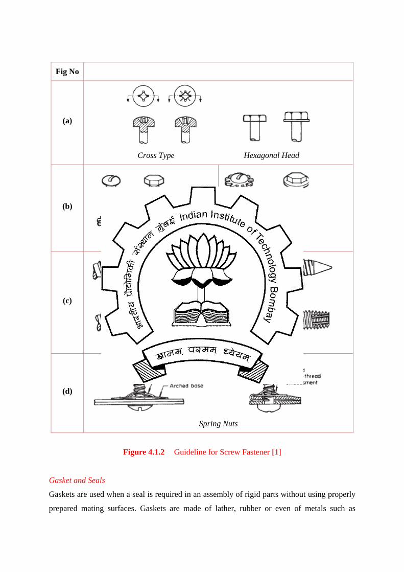
Fig No
(a)
Cross Type Hexagonal Head
(b)
(c)
Self-tapping screw
(d)
Spring Nuts
Figure 4.1.2 Guideline for Screw Fastener [1]
Gasket and Seals
Gaskets are used when a seal is required in an assembly of rigid parts without using properly
prepared mating surfaces. Gaskets are made of lather, rubber or even of metals such as

copper and drastically reduce the manufacturing cost. Followings are a few design guidelines
to make gaskets sufficiently economical in an assembly:
1. The gasket shape should be kept as simple as the product design permits.
2. Use circular sized (‘O’) or other standard gasket instead of a specially designed one.
3. Requirement of a gasket can be avoided by making one of the basic parts of the
assembly of plastic, rubber or other flexible material.
4. Gasket width of at least 3 mm is recommended to prevent damage from handling or
assembly.
5. In threaded joints, at least one of the flange faces should have a smooth surface to
avoid cutting or tearing the gasket.
Adhesive Bonded Assembly Adhesive bonds are made by putting a thin film of liquid or semisolid adhesive between the
parts and immobilizing the assembly until it solidifies. Adhesive may be in the solid or
molten state or in liquid form. Adhesive bonding can be employed if one or more of the
following characteristics are required from the assembly.
1. Weight of the finished assembly is not significantly large.
2. Porous, fragile, heat sensitive materials are to be joined.
3. Other fastening method cannot be applied either due to unsatisfactory appearance or
due to the possibility of damaging the parts during application of other joining
methods.
4. The joined part must be electrically insulated to prevent galvanic corrosion.
Followings are a few design recommendations for adhesive joints:
1. As adhesive bonds resist shear, tensile, and compressive forces better than cleavage,
design assemblies which will be subjected to similar load bearing applications [Figure
4.1.3(a)].
2. The width of the joint overlap is more important than the joint length. Bond strength
is proportional to the joint area only in the case of compressive and tensile forces. In
assemblies loaded under shear forces, the stresses are concentrated at the joints end
[Figure 4.1.3(b)].
3. The thermal expansion coefficients of bonded parts should be as close as possible. A
large difference in expansion coefficient would generate large shear stress when
exposed to thermal gradients.

4. The surface preparation is a major step in adhesive bonding. Both the surfaces of the
bonded parts should be cleaned properly to get a sound joint. Vapour degreasing and
solvent wiping techniques may be applied to clean the surfaces. Smooth surfaces are
preferred as these are more easily wet by spreading liquid adhesive.
5. Simple butt joints should be used only when fairly large bonded surfaces are involved
and when cleavage stresses cannot be anticipated [Figure 4.1.3(c)].
Fig no Feasible Better and preferred
a
b
c
Figure 4.1.3 Design recommendations for Adhesive Joints [1]
Welding Welding is a process in which material of the similar type or class are brought together and
joined through the formation of primary (and, occasionally, secondary) chemical bonds under
the combined action of heat and pressure. Weldability of a material depends upon various
factors like the metallurgical changes that are expected to occur during welding, gas
evolution and absorption, extent of oxidation, etc. Some typical applications of welding
include the fabrication of ships, pressure vessels, automobile bodies, off shore platforms,
bridges, welded pipes etc. Figure 4.1.4 shows the classification of various welding processes
as per the American Welding Society. Various welding process differ in the manner in which
pressure and temperature are combined and achieved. A short introduction of various welding
processes is given below. Design guidelines for welded joints are explained briefly in the
subsequent lectures.
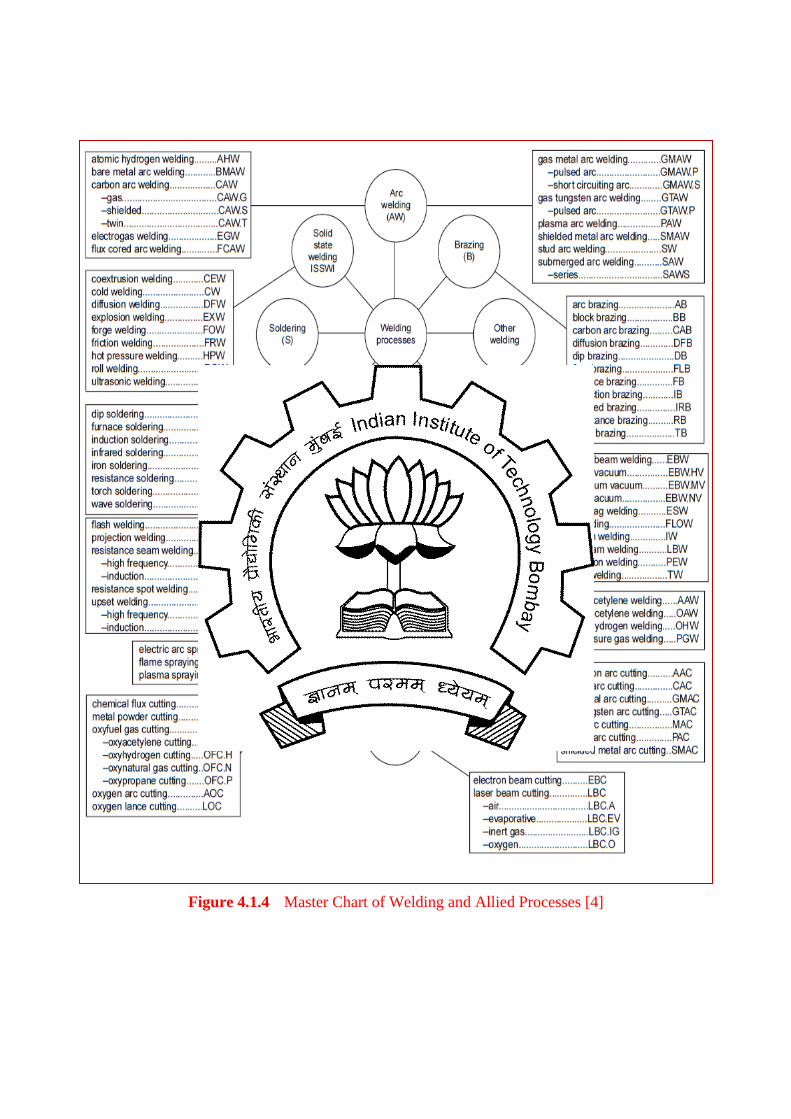
Figure 4.1.4 Master Chart of Welding and Allied Processes [4]
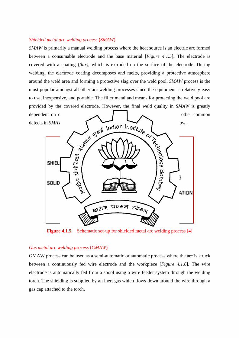
Shielded metal arc welding process (SMAW)
SMAW is primarily a manual welding process where the heat source is an electric arc formed
between a consumable electrode and the base material [Figure 4.1.5]. The electrode is
covered with a coating (flux), which is extruded on the surface of the electrode. During
welding, the electrode coating decomposes and melts, providing a protective atmosphere
around the weld area and forming a protective slag over the weld pool. SMAW process is the
most popular amongst all other arc welding processes since the equipment is relatively easy
to use, inexpensive, and portable. The filler metal and means for protecting the weld pool are
provided by the covered electrode. However, the final weld quality in SMAW is greatly
dependent on operator’s skill. Entrapment of slag and lack of fusion are other common
defects in SMAW. Since SMAW is a manual process, the productivity is quite low.
Figure 4.1.5 Schematic set-up for shielded metal arc welding process [4]
Gas metal arc welding process (GMAW)
GMAW process can be used as a semi-automatic or automatic process where the arc is struck
between a continuously fed wire electrode and the workpiece [Figure 4.1.6]. The wire
electrode is automatically fed from a spool using a wire feeder system through the welding
torch. The shielding is supplied by an inert gas which flows down around the wire through a
gas cap attached to the torch.
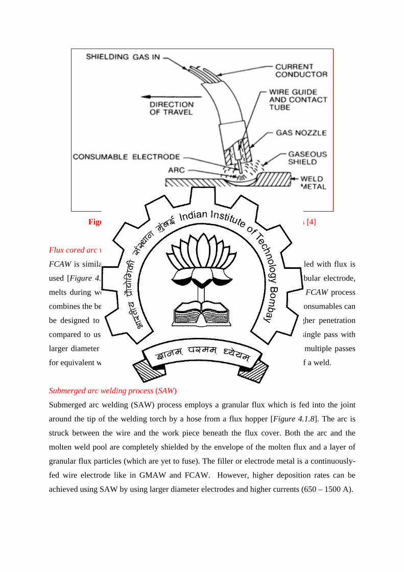
Figure 4.1.6 Schematic set-up for gas metal arc welding process [4]
Flux cored arc welding process (FCAW)
FCAW is similar to GMAW except the fact that a tubular wire electrode filled with flux is
used [Figure 4.1.7]. The flux, which is contained within the core of the tubular electrode,
melts during welding and shields the weld pool from the atmosphere. The FCAW process
combines the best characteristics of SMAW and GMAW. The flux for FCAW consumables can
be designed to support larger weld pools out of position and provide higher penetration
compared to using a solid wire (GMAW). Larger welds can be made in a single pass with
larger diameter electrodes in FCAW where GMAW and SMAW would need multiple passes
for equivalent weld sizes. This improves productivity and reduces distortion of a weld.
Submerged arc welding process (SAW)
Submerged arc welding (SAW) process employs a granular flux which is fed into the joint
around the tip of the welding torch by a hose from a flux hopper [Figure 4.1.8]. The arc is
struck between the wire and the work piece beneath the flux cover. Both the arc and the
molten weld pool are completely shielded by the envelope of the molten flux and a layer of
granular flux particles (which are yet to fuse). The filler or electrode metal is a continuously-
fed wire electrode like in GMAW and FCAW. However, higher deposition rates can be
achieved using SAW by using larger diameter electrodes and higher currents (650 – 1500 A).
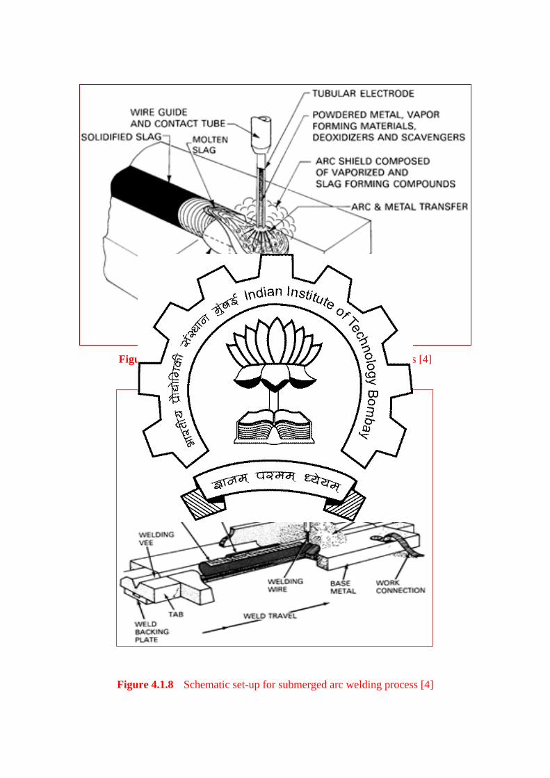
Figure 4.1.7 Schematic set-up for flux cored arc welding process [4]
Figure 4.1.8 Schematic set-up for submerged arc welding process [4]
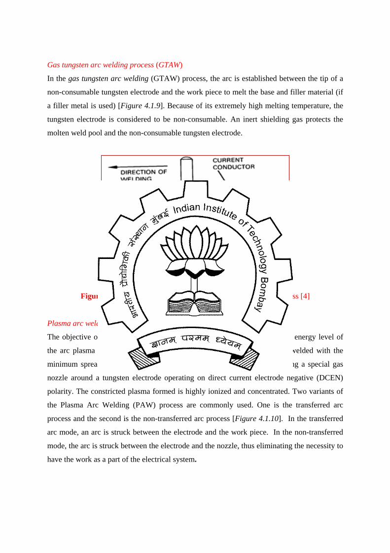
Gas tungsten arc welding process (GTAW)
In the gas tungsten arc welding (GTAW) process, the arc is established between the tip of a
non-consumable tungsten electrode and the work piece to melt the base and filler material (if
a filler metal is used) [Figure 4.1.9]. Because of its extremely high melting temperature, the
tungsten electrode is considered to be non-consumable. An inert shielding gas protects the
molten weld pool and the non-consumable tungsten electrode.
Figure 4.1.9 Schematic set-up for gas tungsten arc welding process [4]
Plasma arc welding process (PAW)
The objective of the Plasma Arc Welding (PAW) process is to increase the energy level of
the arc plasma in a controlled manner such that greater thickness can be welded with the
minimum spread of the welding arc. This objective is achieved by providing a special gas
nozzle around a tungsten electrode operating on direct current electrode negative (DCEN)
polarity. The constricted plasma formed is highly ionized and concentrated. Two variants of
the Plasma Arc Welding (PAW) process are commonly used. One is the transferred arc
process and the second is the non-transferred arc process [Figure 4.1.10]. In the transferred
arc mode, an arc is struck between the electrode and the work piece. In the non-transferred
mode, the arc is struck between the electrode and the nozzle, thus eliminating the necessity to
have the work as a part of the electrical system.

Figure 4.1.10 Schematic set-up for plasma arc welding process [4]
Resistance Spot and Seam Welding
In this process, water-cooled, copper electrodes are used to clamp the sheets to be welded
into place [Figure 4.1.11(a)]. The force applied to the electrodes ensures intimate contact
between all the parts in the weld configuration. A current is then passed across the electrodes
through the sheets. The contact resistance between the two pieces of sheet metal to be joined
is much higher than the bulk resistance of the copper electrodes or of the sheet metal itself.
Therefore, the highest resistive heating occurs between the two pieces of sheet metal. As
current continues to flow, melting occurs and a weld nugget is formed between the two
sheets. On termination of the welding current, the weld cools rapidly under the influence of
the chilled electrodes. This causes the nugget to solidify, joining the two sheets of metal.
Resistance spot welding is used extensively because it is a simple, fast, inexpensive, and
versatile process, and also easy to automate. Resistance seam welding is a process of
continuous joining of overlapping sheets by passing them between two rotating electrode
wheels [Figure 4.1.11(b)]. Heat generated by the electric current flowing through the contact
area and pressure provided by the wheels are sufficient to produce a leak-tight weld.
Resistance seam welding is a high speed and clean process, which is used when continuous
tight weld is required (fuel tanks, drums, domestic radiators).

Figure 4.1.11 (a) Resistance spot welding, (b) Resistance seam welding
Various other joining processes like laser beam welding, electron beam welding, electroslag
welding, thermit welding, brazing and soldering also find application in engineering field.
Brazing and Soldering Processes
Brazing and soldering fall in the category of solid-liquid joining processes since only the
filler material and not the base materials melts during these processes. The parts to be joined
are fitted together with tight tolerances and a liquid filler is distributed between the mating
surfaces by capillary action. Though the base metals do not melt, still joining can be
performed between the work materials which are otherwise unweldable.
Brazing is a solid-liquid joining process, whereby the molten filler metal (the braze) is drawn
into the gap between closely adjacent surfaces of parent materials by capillary attraction. The
melting point of the filler metal is usually above 450°C, but always below the melting
temperature of the parent material. To achieve a perfect joint, the filler and parent materials
should be metallurgically compatible. There are many ways of brazing, and they all differ in
the method of applying heat to the braze assembly, in particular, the joint area for the melting
of the filler material. These include dip brazing, furnace brazing, induction brazing, infrared
brazing, resistance brazing and torch brazing. Figure 4.1.12 depicts a schematic set-up of
furnace brazing process. Some of common brazing filler alloys include aluminum-silicon,
copper-silver, copper-zinc, gold-silver, etc. [5].
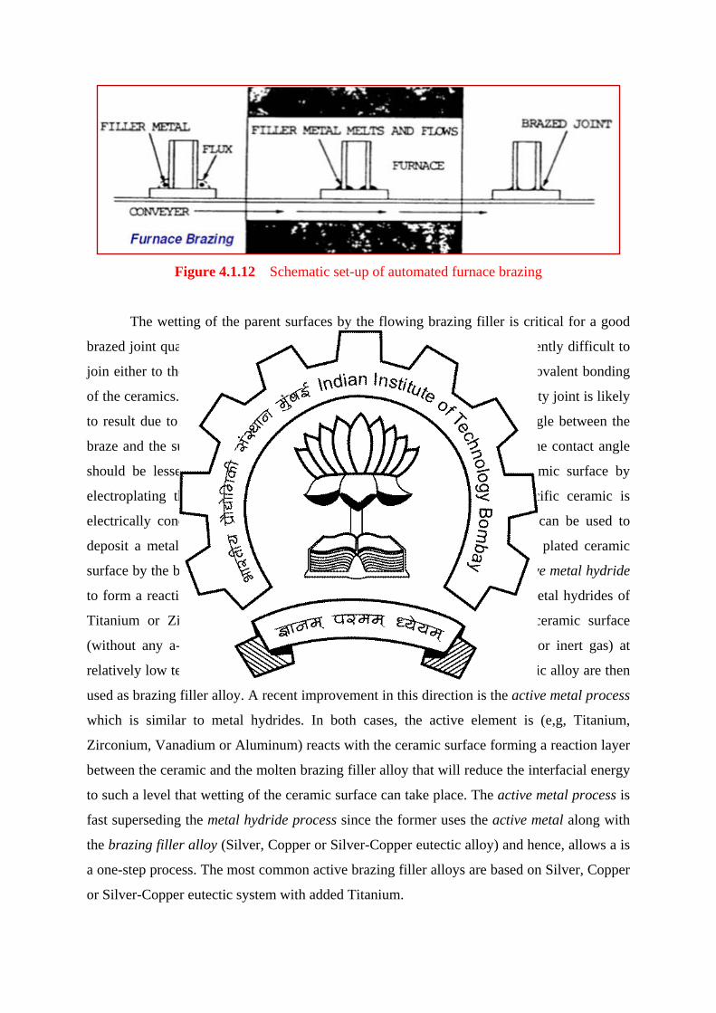
Figure 4.1.12 Schematic set-up of automated furnace brazing
The wetting of the parent surfaces by the flowing brazing filler is critical for a good
brazed joint quality. This is critical, in particular, for ceramics that are inherently difficult to
join either to themselves of to metal structures due to the strong ionic and covalent bonding
of the ceramics. If a braze alloy is melted between two ceramics, a poor quality joint is likely
to result due to poor wetting, which is measured in terms of the contact angle between the
braze and the substrate (ceramic surface) after melting. For good wetting, the contact angle
should be lesser than 900. One common remedy is to metallise the ceramic surface by
electroplating the same to be brazed with Nickel or Copper if the specific ceramic is
electrically conductive. Alternately, vapor deposition or a sputter coating can be used to
deposit a metal onto the ceramic surface and subsequently, wetting of the plated ceramic
surface by the brazing filler can improve. Another approach is to use an active metal hydride
to form a reaction layer between the ceramic and the brazing filler alloy. Metal hydrides of
Titanium or Zirconium are reduced and brazed simultaneously on the ceramic surface
(without any a-priori metallization) in a controlled atomosphere (vacuum or inert gas) at
relatively low temperature. Typically, Silver, Copper or Silver-Copper eutectic alloy are then
used as brazing filler alloy. A recent improvement in this direction is the active metal process
which is similar to metal hydrides. In both cases, the active element is (e,g, Titanium,
Zirconium, Vanadium or Aluminum) reacts with the ceramic surface forming a reaction layer
between the ceramic and the molten brazing filler alloy that will reduce the interfacial energy
to such a level that wetting of the ceramic surface can take place. The active metal process is
fast superseding the metal hydride process since the former uses the active metal along with
the brazing filler alloy (Silver, Copper or Silver-Copper eutectic alloy) and hence, allows a is
a one-step process. The most common active brazing filler alloys are based on Silver, Copper
or Silver-Copper eutectic system with added Titanium.

Figure 4.1.13 Schematic pictures showing poor (left) and good (right) wetting [5]
Soldering refers to a typical group of solid-liquid joining processes that produce coalescence
between the parts to be joined by heating them to the soldering temperature and by using a
filler metal having liquidus temperature not exceeding 450ºC and below the solidus of the
base metals. Usually, a nonferrous alloy is used as the solder material. Like brazing process,
there are different types of soldering process viz. dip soldering, furnace soldering, induction
soldering, infrared soldering, resistance soldering, torch soldering and wave soldering. The
solders are classified according to whether or not they contain lead. The most common
general-purpose solder confirms to a typical Pb (50%) and Sn (50%) composition. Figure
4.1.14 shows a typical soldering action.
Figure 4.1.14 Actions performed during soldering
Guidelines for Part Handling Part handling is very significant during the assembly operation. Following are a set of
guidelines that should be followed for the ease of handling:
1. Design parts that have end-to end symmetry and rotational symmetry about the axis of
rotation.
2. Provide feature that will prevent jamming of parts.
3. Avoid feature that will allow tangling of parts when stored in bulk.
4. Avoid parts that stick together or are slippery, flexible, very small or large, hazardous
to handler.
Guideline for Insertion and fastening 1. Provide chamfer for little or no resistance for insertion and to guide two mating parts
[Figure 4.1.15(a)]. 2. Standardize by using common parts, process and methods across all model to permit
the use of higher volume processes [Figure 4.1.15(b)]. 3. Use pyramid assembly [Figure 4.1.15(c)]. 4. Avoid the necessity for holding parts down to maintain their orientation during
manipulation of the subassembly [Figure 4.1.15(d)]. 5. Design so that a part is located properly before it is released [Figure 4.1.15(e)].
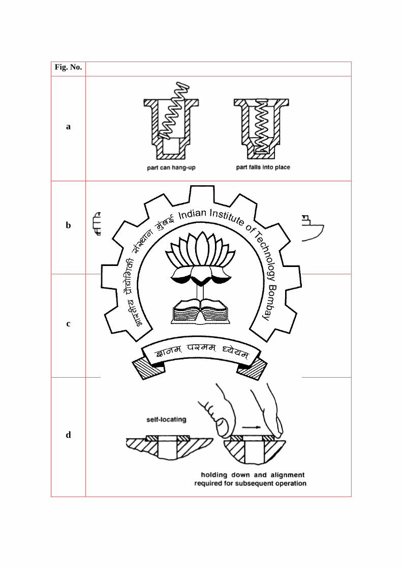
Fig. No.
a
b
c
d

e
Figure 4.1.15 Guidelines for Assembly [2]
Exercise 1. Give examples of permanent and temporary types of joining methods.
2. How the design of electrodes will change when plates of different thickness have to
be spot weld?
3. Distinguish between friction welding and friction stir welding.
References 1. James G. Bralla, Design For Manufacturability Handbook, McGraw Hill, 1999.
2. G. Boothroyd, P. Dewhurst, W. A. Knight, Product Design for Manufacture and
Assembly, Marcel Dekker, 2002.
3. R. S. Parmar, Welding Engineering and Technology, Khanna Publishers, 2004.
4. AWS Welding Handbook (Welding Processes – Part 1), 9th Edition, Volume 2.
5. http://en.wikipedia.org/wiki/Brazing.
6. http://www.azom.com/article.aspx?ArticleID=1079