module overview - plc based industrial automation … 2600 module is fully programmable from the...
TRANSCRIPT

20 Gear Drive, Plymouth Industrial Park, Terryville, CT 06786 page: 1 of 39 Tel: (860) 585-1254 Fax: (860) 584-1973 Web: www.amci.com
2600 Module Manual MicroLogix 1500 & CompactLogix Resolver PLS Module
Revision 1.1
Module Overview
The 2600 module is a high speed limit switch module that resides in a Rockwell Automation CompactlLogix or MicroLogix 1500 system rack, connects to a resolver and switches outputs based on that resolver position which ranges from 0 to 4095 for each rotation (0.088 degree resolution). Based on the change of the resolver position it also transmits a 5V quadrature differential signal with 1024 pulse per revolutions. There are three versions of the 2600 module. The 2611 consist of the resolver interface module and has 16 virtual, backplane only, inputs and outputs. The 2612 module adds one I/O module containing 8 physical inputs and 8 physical outputs to the 2611. The 2613 adds two I/O modules to the 2611 for a total of 16 physical inputs and 16 physical outputs. The virtual inputs and outputs are always numbered 0 to 15 while the physical inputs and outputs are numbered 16 to 31. Each output can be programmed with 16 On/Off setpoints. Alternatively, each of the outputs can be programmed for stitching operations or as timed outputs. The outputs can be Anded with the inputs, and or with the speed of the rotating resolver. The 2600 module is fully programmable from the ladder logic program using a handshaking sequence; no special software packages are required. The module will accept the data located in the output registers as programming data whenever it detects either a 0 to 1 or a 1 to 0 transition of a bit, named the Transmit Bit, in the output registers. The module also has the ability to store all of its parameters in a Flash memory. If this feature is not used, the module will have to be programmed at every power up. The Flash Memory device can be programmed a minimum of 10,000 times. The throughput time of the 2600 module is less than 20 microseconds. The repeatability of the output firing, that is how much the output will vary from one turn to the next, is 1 microsecond. All three versions of the 2600 module have the ability to both output and receive serial position data, allowing multiple units to be “slaved” together.
Sample programs showing how to program the 2600 module in both MicroLogix and CompactLogix systems are available from the following page of our website. http://www.amci.com/sampleprograms.asp

20 Gear Drive, Plymouth Industrial Park, Terryville, CT 06786 page: 2 of 39 Tel: (860) 585-1254 Fax: (860) 584-1973 Web: www.amci.com
2600 Module Manual MicroLogix 1500 & CompactLogix Resolver PLS Module
Revision 1.1
General Information Important User Information The products and application data described in this manual are useful in a wide variety of different applications. Therefore, the user and others responsible for applying these products described herein are responsible for determining the acceptability for each application. While efforts have been made to provide accurate information within this manual, AMCI assumes no responsibility for the application or the completeness of the information contained herein. Throughout this manual the following two notices are used to highlight important points. WARNINGS tell you when people may be hurt or equipment may be damaged if the procedure is not followed properly. CAUTIONS tell you when equipment may be damaged if the procedure is not followed properly. No patent liability is assumed by AMCI, with respect to use of information, circuits, equipment, or software described in this manual. The information contained within this manual is subject to change without notice. UNDER NO CIRCUMSTANCES WILL ADVANCED MICRO CONTROLS, INC. BE RESPONSIBLE OR LIABLE FOR ANY DAMAGES OR LOSSES, INCLUDING INDIRECT OR CONSEQUENTIAL DAMAGES OR LOSSES, ARISING FROM THE USE OF ANY INFORMATION CONTAINED WITHIN THIS MANUAL, OR THE USE OF ANY PRODUCTS OR SERVICES REFERENCED HEREIN. Standard Warranty ADVANCED MICRO CONTROLS, INC. warrants that all equipment manufactured by it will be free from defects, under normal use, in materials and workmanship for a period of [18] months. Within this warranty period, AMCI shall, at its option, repair or replace, free of charge, any equipment covered by this warranty which is returned, shipping charges prepaid, within one year from date of invoice, and which upon examination proves to be defective in material or workmanship and not caused by accident, misuse, neglect, alteration, improper installation or improper testing. The provisions of the “STANDARD WARRANTY” are the sole obligations of AMCI and excludes all other warranties expressed or implied. In no event shall AMCI be liable for incidental or consequential damages or for delay in performance of this warranty. Returns Policy All equipment being returned to AMCI for repair or replacement, regardless of warranty status, must have a Return Merchandise Authorization number issued by AMCI. Call (860) 585-1254 with the model and serial numbers along with a description of the problem. A “RMA” number will be issued. Equipment must be shipped to AMCI with transportation charges prepaid. Title and risk of loss or damage remains with the customer until shipment is received by AMCI. 24 Hour Technical Support Number Technical Support, in the form of documents, FAQs, and sample programs, is available from our website, www.amci.com. 24 Hour technical support is also available on this product. For technical support, call (860) 583-7271. Your call will be answered at the factory during regular business hours, Monday through Friday, 8AM - 5PM EST. During non-business hours, an automated system will ask you to leave a detailed message and the telephone number that you can be reached at. The system will page an engineer on call. Please have your product model number and a description of the problem ready before you call.
20 Gear Drive, Plymouth Industrial Park, Terryville, CT 06786 page: 3 of 39 Tel: (860) 585-1254 Fax: (860) 584-1973 Web: www.amci.com
2600 Module Manual MicroLogix 1500 & CompactLogix Resolver PLS Module
Revision 1.1
Table of Contents Installing the 2600 Module Chapter 1 4 Configuring a CompactLogix System 4 Configuring a MicroLogix System 5 Hardware Overview Chapter 2 6 Module Specifications 6 Quadrature Output 7 Flash Memory 7 Front Panel & LED Function 8 Main Module Wiring 9 I/O Module Wiring 11 Programmable Parameters Chapter 3 12 Global Configuration Data 12 Global Machine Offset Data 15 Limit Switch Data 16 Stitching Output Data 17 Speed Compensation Advances & Timed Outputs Data 18 ANDing Functions 21 Limit Switch Shifting Data 23 Forcing, Virtual Input, and Get Attributes Data 24 Save Configuration Data 26 Output Registers Chapter 4 27 Programming Sequence 27 General Control Programming Block 27 Global Configuration Programming Block 28 Global Machine Offset Programming Block 30 Limit Switch Programming Block 31 Speed Compensation Advances & Timed Outputs Programming Block 32 ANDing Functions Programming Block 33 Limit Switch Shifting Programming Block 34 Forcing, Virtual Input, and Get Attributes Programming Block 35 Save Configuration Programming Block 36 Input Registers Chapter 5 37 Status Word 37
Programming Error Codes 38 Displayed Attribute Table 39 Revision History Chapter 6 39
20 Gear Drive, Plymouth Industrial Park, Terryville, CT 06786 page: 4 of 39 Tel: (860) 585-1254 Fax: (860) 584-1973 Web: www.amci.com
2600 Module Manual MicroLogix 1500 & CompactLogix Resolver PLS Module
Revision 1.1
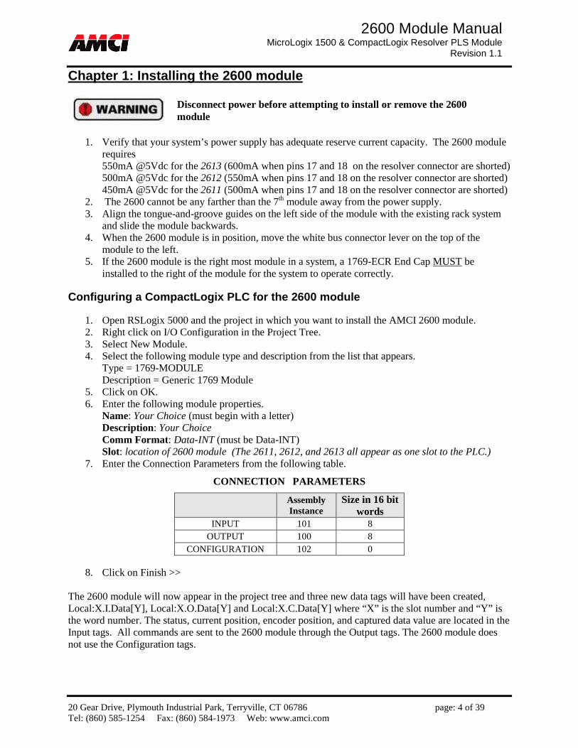
Chapter 1: Installing the 2600 module
1. Verify that your system’s power supply has adequate reserve current capacity. The 2600 module requires 550mA @5Vdc for the 2613 (600mA when pins 17 and 18 on the resolver connector are shorted) 500mA @5Vdc for the 2612 (550mA when pins 17 and 18 on the resolver connector are shorted) 450mA @5Vdc for the 2611 (500mA when pins 17 and 18 on the resolver connector are shorted)
2. The 2600 cannot be any farther than the 7th module away from the power supply. 3. Align the tongue-and-groove guides on the left side of the module with the existing rack system
and slide the module backwards. 4. When the 2600 module is in position, move the white bus connector lever on the top of the
module to the left. 5. If the 2600 module is the right most module in a system, a 1769-ECR End Cap MUST be
installed to the right of the module for the system to operate correctly. Configuring a CompactLogix PLC for the 2600 module
1. Open RSLogix 5000 and the project in which you want to install the AMCI 2600 module. 2. Right click on I/O Configuration in the Project Tree. 3. Select New Module. 4. Select the following module type and description from the list that appears.
Type = 1769-MODULE Description = Generic 1769 Module
5. Click on OK. 6. Enter the following module properties.
Name: Your Choice (must begin with a letter) Description: Your Choice Comm Format: Data-INT (must be Data-INT) Slot: location of 2600 module (The 2611, 2612, and 2613 all appear as one slot to the PLC.)
7. Enter the Connection Parameters from the following table.
CONNECTION PARAMETERS
Assembly Instance
Size in 16 bit words
INPUT 101 8 OUTPUT 100 8
CONFIGURATION 102 0
8. Click on Finish >> The 2600 module will now appear in the project tree and three new data tags will have been created, Local:X.I.Data[Y], Local:X.O.Data[Y] and Local:X.C.Data[Y] where “X” is the slot number and “Y” is the word number. The status, current position, encoder position, and captured data value are located in the Input tags. All commands are sent to the 2600 module through the Output tags. The 2600 module does not use the Configuration tags.
Disconnect power before attempting to install or remove the 2600 module
20 Gear Drive, Plymouth Industrial Park, Terryville, CT 06786 page: 5 of 39 Tel: (860) 585-1254 Fax: (860) 584-1973 Web: www.amci.com
2600 Module Manual MicroLogix 1500 & CompactLogix Resolver PLS Module
Revision 1.1
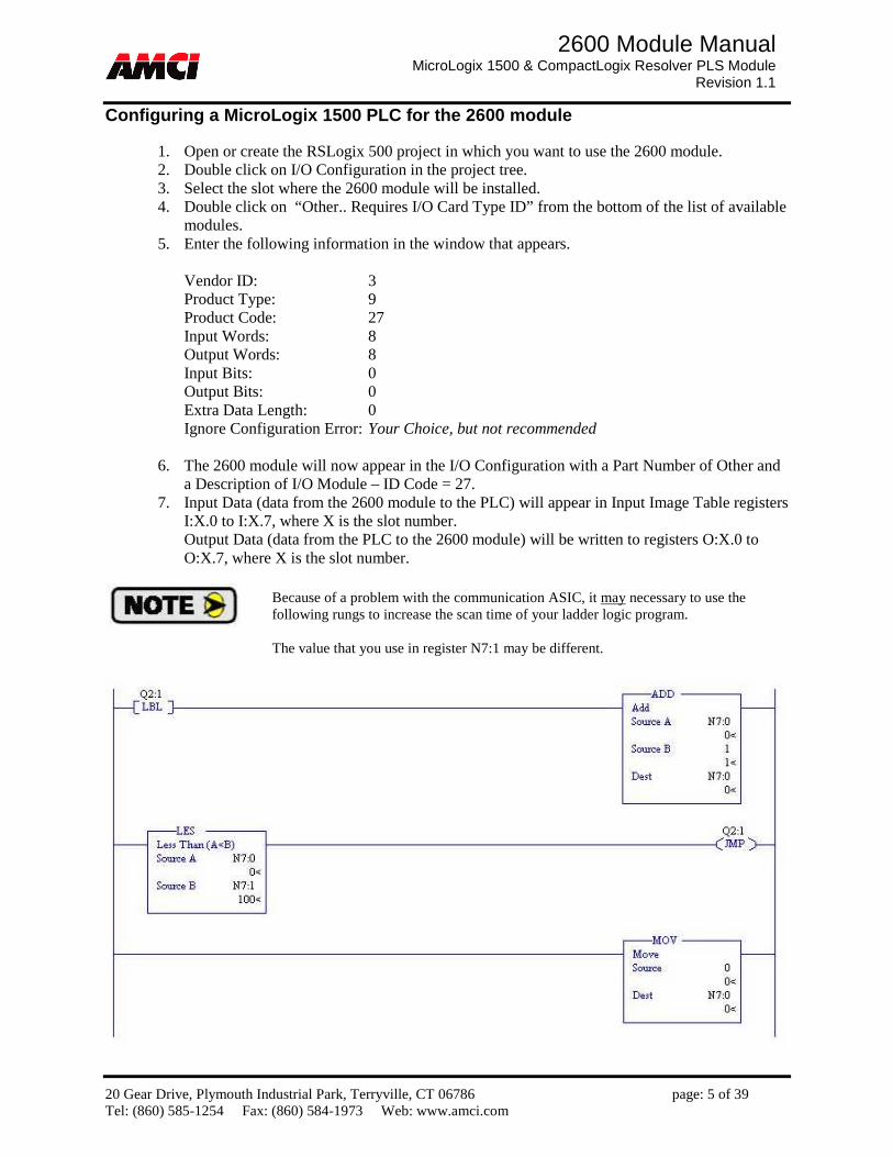
Configuring a MicroLogix 1500 PLC for the 2600 module
1. Open or create the RSLogix 500 project in which you want to use the 2600 module. 2. Double click on I/O Configuration in the project tree. 3. Select the slot where the 2600 module will be installed. 4. Double click on “Other.. Requires I/O Card Type ID” from the bottom of the list of available
modules. 5. Enter the following information in the window that appears.
Vendor ID: 3 Product Type: 9 Product Code: 27 Input Words: 8 Output Words: 8 Input Bits: 0 Output Bits: 0 Extra Data Length: 0 Ignore Configuration Error: Your Choice, but not recommended
6. The 2600 module will now appear in the I/O Configuration with a Part Number of Other and a Description of I/O Module – ID Code = 27.
7. Input Data (data from the 2600 module to the PLC) will appear in Input Image Table registers I:X.0 to I:X.7, where X is the slot number. Output Data (data from the PLC to the 2600 module) will be written to registers O:X.0 to O:X.7, where X is the slot number.
Because of a problem with the communication ASIC, it may necessary to use the following rungs to increase the scan time of your ladder logic program. The value that you use in register N7:1 may be different.

20 Gear Drive, Plymouth Industrial Park, Terryville, CT 06786 page: 6 of 39 Tel: (860) 585-1254 Fax: (860) 584-1973 Web: www.amci.com
2600 Module Manual MicroLogix 1500 & CompactLogix Resolver PLS Module
Revision 1.1
Chapter 2: Hardware Overview
Module Specifications Current Draw 2613: 550mA @5Vdc (600mA when pins 17 and 18 on the resolver connector are shorted) 2612: 500mA @5Vdc (550mA when pins 17 and 18 on the resolver connector are shorted) 2611: 450mA @5Vdc (500mA when pins 17 and 18 on the resolver connector are shorted)
Throughput Time from Position Change to Output Reaction (Activation/Deactivation):
• The 2600 PLS module is capable of detecting 0.088 degree changes in a resolver’s position at 1800 RPM.
• Master Module: 10 microseconds to 20 microseconds depending on load and the programmed PLS configuration
• Slave Module: The Slave module will operate about 0.05ms behind the Master Module.
Repeatability of Output Reaction on Position Change (Jitter when positioning): • 1 microsecond (The is the repeatability of the output firing, that is how much it will vary from
one turn to the next.) Velocity Update
• The velocity data is always reported in Revolutions per Minute (RPM). • The 2600 PLS module calculates resolver for given Resolver Rollover Counts. Positive RPM
indicates increasing counts, and a negative RPM indicates decreasing counts. The increasing count direction can be changed by a bit in the PLS Global Configuration, or by reversing the S2 S4 resolver signals wires.
• The 2600 RPM value is updated every 14.6mS applying a first order digital filter with programmable RPM Filter value.
Environmental Conditions
• Operating Temperature: 0 to 60° C • Relative Humidity: 5 to 95% (non-condensing) • Storage Temperature: -40 to 85° C
Sinking Inputs
Nominal Voltage Range: 12 to 24Vdc On State: 10 to 30Vdc Off State: 0 to 5Vdc Impedance @ 24Vdc: 3.3kOhm Input Current 8mA @ 24Vdc, 3.75mA @12Vdc Isolation Inputs are isolated from PLC backplane
20 Gear Drive, Plymouth Industrial Park, Terryville, CT 06786 page: 7 of 39 Tel: (860) 585-1254 Fax: (860) 584-1973 Web: www.amci.com
2600 Module Manual MicroLogix 1500 & CompactLogix Resolver PLS Module
Revision 1.1
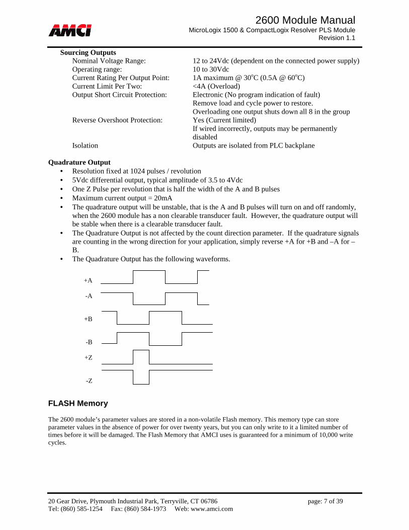
Sourcing Outputs Nominal Voltage Range: 12 to 24Vdc (dependent on the connected power supply) Operating range: 10 to 30Vdc Current Rating Per Output Point: 1A maximum @ 30oC (0.5A @ 60oC) Current Limit Per Two: <4A (Overload) Output Short Circuit Protection: Electronic (No program indication of fault)
Remove load and cycle power to restore. Overloading one output shuts down all 8 in the group
Reverse Overshoot Protection: Yes (Current limited) If wired incorrectly, outputs may be permanently disabled
Isolation Outputs are isolated from PLC backplane
Quadrature Output • Resolution fixed at 1024 pulses / revolution • 5Vdc differential output, typical amplitude of 3.5 to 4Vdc • One Z Pulse per revolution that is half the width of the A and B pulses • Maximum current output = 20mA • The quadrature output will be unstable, that is the A and B pulses will turn on and off randomly,
when the 2600 module has a non clearable transducer fault. However, the quadrature output will be stable when there is a clearable transducer fault.
• The Quadrature Output is not affected by the count direction parameter. If the quadrature signals are counting in the wrong direction for your application, simply reverse +A for +B and –A for –B.
• The Quadrature Output has the following waveforms. FLASH Memory The 2600 module’s parameter values are stored in a non-volatile Flash memory. This memory type can store parameter values in the absence of power for over twenty years, but you can only write to it a limited number of times before it will be damaged. The Flash Memory that AMCI uses is guaranteed for a minimum of 10,000 write cycles.
+A
-A
+B
-B
+Z
-Z

20 Gear Drive, Plymouth Industrial Park, Terryville, CT 06786 page: 8 of 39 Tel: (860) 585-1254 Fax: (860) 584-1973 Web: www.amci.com
2600 Module Manual MicroLogix 1500 & CompactLogix Resolver PLS Module
Revision 1.1
Main Panel I/O Panel 1 I/O Panel 2 LED Functions
PLS
Module Fault Status
Module LED Solid Green: Module Owned, two-way communication; Master Module Fault LED Solid Red: Module Fault (faulty Flash Memory or no reference voltage)
Non-Clearable Transducer Fault Blinking Red: Clearable Transducer Fault; Slave Module Fault LED Solid Red: Module Fault (faulty Flash Memory or no reference voltage),
Serial data signals are not present Master Module has a Clearable or Non-Clearable Transducer Fault
Blinking Red: Clearable Transducer Fault Status LED Solid Green: Module and Transducer are working fine; Blinking Green: Outputs are overridden (forced); Fuse LED Solid Red: Outputs overloaded Main module not communicating with I/O module. Pwr LED Solid Green: Outputs working normally In/Out_xx LED Solid Yellow: Input/Output_xx activated
Fuse O16 O20 I16 I20 Pwr O17 O21 I17 I21 O18 O22 I18 I22 O19 O23 I19 I23
Fuse O24 O28 I24 I28 Pwr O25 O29 I25 I29 O26 O30 I26 I30 O27 O31 I27 I31
PLS PLS
20 Gear Drive, Plymouth Industrial Park, Terryville, CT 06786 page: 9 of 39 Tel: (860) 585-1254 Fax: (860) 584-1973 Web: www.amci.com
2600 Module Manual MicroLogix 1500 & CompactLogix Resolver PLS Module
Revision 1.1
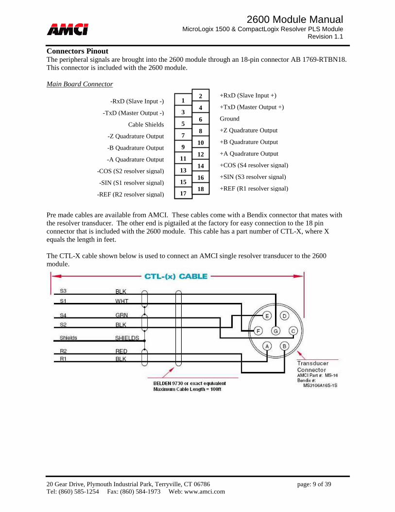
Connectors Pinout The peripheral signals are brought into the 2600 module through an 18-pin connector AB 1769-RTBN18. This connector is included with the 2600 module.
Main Board Connector Pre made cables are available from AMCI. These cables come with a Bendix connector that mates with the resolver transducer. The other end is pigtailed at the factory for easy connection to the 18 pin connector that is included with the 2600 module. This cable has a part number of CTL-X, where X equals the length in feet. The CTL-X cable shown below is used to connect an AMCI single resolver transducer to the 2600 module.
-RxD (Slave Input -)
-TxD (Master Output -)
Cable Shields
-Z Quadrature Output
-B Quadrature Output
-A Quadrature Output
-COS (S2 resolver signal)
-SIN (S1 resolver signal)
-REF (R2 resolver signal)
+RxD (Slave Input +)
+TxD (Master Output +)
Ground
+Z Quadrature Output
+B Quadrature Output
+A Quadrature Output
+COS (S4 resolver signal)
+SIN (S3 resolver signal)
+REF (R1 resolver signal)
1
3
5
7
9
111 13
15
17
2
4
6
8
10
12
14
16
18
20 Gear Drive, Plymouth Industrial Park, Terryville, CT 06786 page: 10 of 39 Tel: (860) 585-1254 Fax: (860) 584-1973 Web: www.amci.com
2600 Module Manual MicroLogix 1500 & CompactLogix Resolver PLS Module
Revision 1.1
Wiring Notes
• When plugged into the 2600 module, pin 1 is located in the upper left hand corner. • The cable between the resolver and the module can have a maximum length of 100ft. • The reference voltage output on the R1 & R2 terminals has an amplitude of 1.35Vrms and a frequency of
10kHz. • Transducer signals are generally low voltage, low power signals. If you are using A-B guidelines for cabling
installation, treat the transducer cable as a Category 2 cable. It can be installed in conduit along with other low power cabling such as communication cables and low power ac/dc I/O lines. It cannot be installed in conduit with ac power lines or high power ac/dc I/O lines.
• Like all signal and communication cable, the transducer cable should be shielded. These shields must be grounded only at one end of the cable. Because the rack cabinet is typically better grounded than the machine, AMCI recommends that the cable shields be terminated at the 2600 module.
• If a junction must be made in the signal cable, treat the shield as a signal-carrying conductor. Do not connect the shield to ground at any junction box or the transducer.
• If the signal cable must cross power feed lines, it should do so at right angles. • Route the cable at least five feet from high voltage enclosures, or sources of “rf” radiation. • The Ground Terminal pin 6 and the Cable Shields Terminal pin 5 are internally connected together. • The Cable Shields pin 5 is connected to the rack’s chassis ground. The cable shields should be connected to
these terminals. If you are still experiencing noise related problems, try running a heavy wire directly from the cable shields pin to your Earth Ground bus.
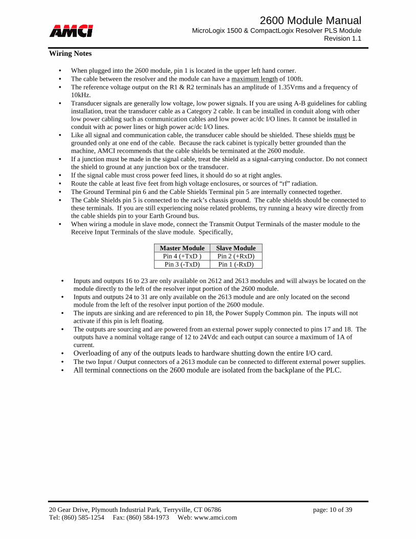
• When wiring a module in slave mode, connect the Transmit Output Terminals of the master module to the Receive Input Terminals of the slave module. Specifically,
Master Module Slave Module Pin 4 (+TxD ) Pin 2 (+RxD) Pin 3 (-TxD) Pin 1 (-RxD)
• Inputs and outputs 16 to 23 are only available on 2612 and 2613 modules and will always be located on the
module directly to the left of the resolver input portion of the 2600 module. • Inputs and outputs 24 to 31 are only available on the 2613 module and are only located on the second
module from the left of the resolver input portion of the 2600 module. • The inputs are sinking and are referenced to pin 18, the Power Supply Common pin. The inputs will not
activate if this pin is left floating. • The outputs are sourcing and are powered from an external power supply connected to pins 17 and 18. The
outputs have a nominal voltage range of 12 to 24Vdc and each output can source a maximum of 1A of current.
• Overloading of any of the outputs leads to hardware shutting down the entire I/O card. • The two Input / Output connectors of a 2613 module can be connected to different external power supplies. • All terminal connections on the 2600 module are isolated from the backplane of the PLC.
20 Gear Drive, Plymouth Industrial Park, Terryville, CT 06786 page: 11 of 39 Tel: (860) 585-1254 Fax: (860) 584-1973 Web: www.amci.com
2600 Module Manual MicroLogix 1500 & CompactLogix Resolver PLS Module
Revision 1.1
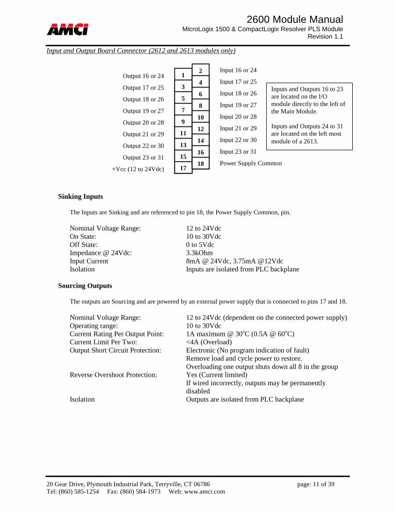
Input and Output Board Connector (2612 and 2613 modules only)
Sinking Inputs
The Inputs are Sinking and are referenced to pin 18, the Power Supply Common, pin.
Nominal Voltage Range: 12 to 24Vdc On State: 10 to 30Vdc Off State: 0 to 5Vdc Impedance @ 24Vdc: 3.3kOhm Input Current 8mA @ 24Vdc, 3.75mA @12Vdc Isolation Inputs are isolated from PLC backplane
Sourcing Outputs
The outputs are Sourcing and are powered by an external power supply that is connected to pins 17 and 18.
Nominal Voltage Range: 12 to 24Vdc (dependent on the connected power supply) Operating range: 10 to 30Vdc Current Rating Per Output Point: 1A maximum @ 30oC (0.5A @ 60oC) Current Limit Per Two: <4A (Overload) Output Short Circuit Protection: Electronic (No program indication of fault)
Remove load and cycle power to restore. Overloading one output shuts down all 8 in the group
Reverse Overshoot Protection: Yes (Current limited) If wired incorrectly, outputs may be permanently disabled
Isolation Outputs are isolated from PLC backplane
Output 16 or 24
Output 17 or 25
Output 18 or 26
Output 19 or 27
Output 20 or 28
Output 21 or 29
Output 22 or 30
Output 23 or 31
+Vcc (12 to 24Vdc)
Input 16 or 24
Input 17 or 25
Input 18 or 26
Input 19 or 27
Input 20 or 28
Input 21 or 29
Input 22 or 30
Input 23 or 31
Power Supply Common
1
3
5
7
9
111 13
15
17
2
4
6
8
10
12
14
16
18
Inputs and Outputs 16 to 23 are located on the I/O module directly to the left of the Main Module. Inputs and Outputs 24 to 31 are located on the left most module of a 2613.

20 Gear Drive, Plymouth Industrial Park, Terryville, CT 06786 page: 12 of 39 Tel: (860) 585-1254 Fax: (860) 584-1973 Web: www.amci.com
2600 Module Manual MicroLogix 1500 & CompactLogix Resolver PLS Module
Revision 1.1
Chapter 3: Programmable Parameters Clear Errors: This command bit exists on all of the programming blocks and will remove a latched
transducer fault and all programming errors. Disable Physical Outputs: This bit exists in all of the programming blocks. Setting this bit will cause all
of the physical outputs to turn off. Resetting this bit will cause the physical outputs to turn on or off based on programmed on/off setpoints, the resolver position, and the state of the ANDing Inputs.
Void Entire setup of Specified Output: This bit exists in all of the Programming Blocks that are used to program when a PLS output will fire. Setting this bit clears the entire setup of the Output defined by the Output Being Programmed parameter. This includes all of the On/Off setpoints, the Limit Offset, and any ANDing functions that have been assigned to the input.
Transmit Bit: This bit exists on all of the programming blocks. The 2600 module only acts on the data located in the output registers on the 0 to 1 and the 1 to 0 transition of this bit.
Global Configuration Data Master / Slave Mode: This bit level parameter configures the 2600 module to be used either as a Master
Module or as a Slave Module. When configured as a slave, the module will receive its position data over a serial link from a 2600 module that has been configured as a Master. When configured as a Slave, the 2600 module follows the direction of the Master module. The default state of this parameter is Master.
Transducer Fault Latch: This bit level parameter configures the 2600 module to either Latch or Self Clear a transducer fault that will occur if the signals between the module and the resolver are interrupted and then restored. A loose connection or electronic noise are two possible causes of interrupted resolver signals. The default state of this parameter has the faults latched.
Hold Last Output State: This bit level parameter allows the outputs to remain in their last state if there is a loss of communication, if there is a transducer fault, or if the PLC is switched to Program Mode. In the case of the transducer fault, the outputs will remain in their last state even if it is a Clearable transducer fault, which is indicated by a blinking Fault LED. The default state of this parameter has the outputs turn off if one or more of the previous conditions are met.
Count Direction: This bit level parameter controls the direction of increasing counts. If the resolver cable is wired as shown in this manual, then the position counts will increase as the resolver’s shaft rotates Clockwise, looking at the shaft. Using the count direction parameter will cause the position counts to increase as the resolver’s shaft rotates Counter Clockwise, looking at the shaft. The default state of this parameter is Clockwise Increasing.
20 Gear Drive, Plymouth Industrial Park, Terryville, CT 06786 page: 13 of 39 Tel: (860) 585-1254 Fax: (860) 584-1973 Web: www.amci.com
2600 Module Manual MicroLogix 1500 & CompactLogix Resolver PLS Module
Revision 1.1
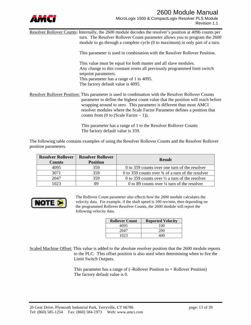
Resolver Rollover Counts: Internally, the 2600 module decodes the resolver’s position at 4096 counts per turn. The Resolver Rollover Count parameter allows you to program the 2600 module to go through a complete cycle (0 to maximum) in only part of a turn. This parameter is used in combination with the Resolver Rollover Position. This value must be equal for both master and all slave modules. Any change to this constant resets all previously programmed limit switch setpoint parameters. This parameter has a range of 1 to 4095. The factory default value is 4095.
Resolver Rollover Position: This parameter is used in combination with the Resolver Rollover Counts
parameter to define the highest count value that the position will reach before wrapping around to zero. This parameter is different than most AMCI resolver modules where the Scale Factor Parameter defines a position that counts from (0 to (Scale Factor – 1)). This parameter has a range of 1 to the Resolver Rollover Counts The factory default value is 359.
The following table contains examples of using the Resolver Rollover Counts and the Resolver Rollover position parameters.
Resolver Rollover Counts
Resolver Rollover Position Result
4095 359 0 to 359 counts over one turn of the resolver 3071 359 0 to 359 counts over ¾ of a turn of the resolver 2047 359 0 to 359 counts over ½ a turn of the resolver 1023 89 0 to 89 counts over ¼ turn of the resolver
Scaled Machine Offset: This value is added to the absolute resolver position that the 2600 module reports
to the PLC. This offset position is also used when determining when to fire the Limit Switch Outputs. This parameter has a range of (–Rollover Position to + Rollover Position) The factory default value is 0.
The Rollover Count parameter also effects how the 2600 module calculates the velocity data. For example, if the shaft speed is 100 rev/min, then depending on the programmed Rollover Resolver Counts, the 2600 module will report the following velocity data.
Rollover Count Reported Velocity 4095 100 2047 200 1023 400
20 Gear Drive, Plymouth Industrial Park, Terryville, CT 06786 page: 14 of 39 Tel: (860) 585-1254 Fax: (860) 584-1973 Web: www.amci.com
2600 Module Manual MicroLogix 1500 & CompactLogix Resolver PLS Module
Revision 1.1
RPM Filter Value: The RPM Filter determines how quickly the velocity value, in RPM, is reported to the PLC. The velocity value is also used internally for the speed compensation calculations. The smaller the RPM Filter Value, the reported RPM matches very closely matches the actual RPM. Higher RPM Filter Values eliminate RPM jitter but increase the lagging to the actual RPM This parameter has a range of 0 to 65535 (0 to FFFFh) The factory default value is 40960 (A000h).
Physical Outputs Inverting Constant: When applied, each bit of this word inverts the state of the
corresponding physical output. Bit 0 controls output 16, bit 1 controls output 17 … bit 15 controls output 31. For example, if output 16 is programmed to turn on at 10 degrees and off at 20 degrees, then using the Physical Outputs Inverting Constant will cause the output to turn on at 20 degrees and off at 10 degrees. The factory default value is 0.
Physical Inputs Inverting Constant: When applied, each bit of this word inverts the corresponding
physical input. Bit 0 controls input 16, bit 1 controls input 17 … bit 15 controls input 31. For example, if input 16 being used and the Physical Inverting Constant bit is reset, then the input will be acted on when the input is receiving power (connected to a normally open contact). If the Physical Inverting Constant bit is set, then the input will be acted on when the input is not receiving power (connected to a normally closed contact). The factory default value is 0.
20 Gear Drive, Plymouth Industrial Park, Terryville, CT 06786 page: 15 of 39 Tel: (860) 585-1254 Fax: (860) 584-1973 Web: www.amci.com
2600 Module Manual MicroLogix 1500 & CompactLogix Resolver PLS Module
Revision 1.1
Global Machine Offset Data Preset Input: This parameter defines the input that, when energized, will set the Scaled Position data equal
to the Preset Value. 2611 module range: 0 to 15 2612 module range: 0 to 23 2613 module range: 0 to 31
Preset Value: The scaled position is set to this value when the Preset Input is energized. The module automatically recalculates the Scaled Machine Offset. The Preset Value has a range of (0 to Resolver Rollover Position) The factory default is 0
Nudge Up Input: This parameter defines the input that, when energized, will increase the Scaled Machine
Offset and the Preset Value by the Nudge Up Value. Because the Scaled Machine Offset is being changed, the Scaled Position data will also be changed. 2611 module range: 0 to 15 2612 module range: 0 to 23 2613 module range: 0 to 31
Nudge Up Value: The Offset and Preset values are increased by this value when the Nudge Up Input is energized. The Nudge Up Value has a range of (0 to Resolver Rollover Position) The factory default is 0
Nudge Down Input: This parameter defines the input that, when energized, will decrease the Scaled
Machine Offset and the Preset Value by the Nudge Down Value. Because the Scaled Machine Offset is being changed, the Scaled Position data will also be changed. 2611 module range: 0 to 15 2612 module range: 0 to 23 2613 module range: 0 to 31
Nudge Down Value: The Offset and Preset values are decreased by this value when the Nudge Down Input is energized. The Nudge Down Value has a range of (0 to Resolver Rollover Position) The factory default is 0
20 Gear Drive, Plymouth Industrial Park, Terryville, CT 06786 page: 16 of 39 Tel: (860) 585-1254 Fax: (860) 584-1973 Web: www.amci.com
2600 Module Manual MicroLogix 1500 & CompactLogix Resolver PLS Module
Revision 1.1
Limit Switch Data Output Being Programmed: This parameter defines to what output the remaining Limit Switch setup
parameters are being assigned to. 2611 module range: 0 to 15 2612 module range: 0 to 23 2613 module range: 0 to 31
Limit Offset: Each of the 2600 modules outputs fires based on its own internal position, which may or may not be equal to the Scaled Machine Position. The Limit Offset parameter is added to this internal position adjusting where the On/Off setpoints fire. Please note that a positive Limit Offset causes the output to turn on earlier and a negative Limit Offset causes the output to turn on later. This parameter has a range of (–Rollover Position to + Rollover Position) The factory default value is 0.
Output Setpoint: Each of the 2600 modules outputs can be programmed with 16 on / off setpoints. This
parameter defines which of these 16 on/off setpoint is being programmed with the current block of data. This parameter has a range of 0 to 15
From Position: This parameter defines the resolver position where the Output Position will turn on. This parameter has a range of (0 to Resolver Rollover Position)
To Position: This parameter defines the resolver position where the Output Position will turn off.
This parameter has a range of (0 to Resolver Rollover Position)
The Limit Switch Output will be on for the entire rotation of the resolver if the From and To setpoints are equal to each other.

20 Gear Drive, Plymouth Industrial Park, Terryville, CT 06786 page: 17 of 39 Tel: (860) 585-1254 Fax: (860) 584-1973 Web: www.amci.com
2600 Module Manual MicroLogix 1500 & CompactLogix Resolver PLS Module
Revision 1.1
Stitching Outputs Data In place of programming multiple On / Off setpoints, it is also possible to program the 2600 module with stitching outputs that that define a pattern that is contained between the From and To Positions. On Stitch Distance: This parameter defines when the Output will be ON between the programmed From
and To positions. For the stitching operation to occur, there must be enough distance between the From and To positions for the output to turn on at least twice. This parameter has a range of (1 to ((To Position – From Position) - 1) / 2)
Off Stitch Distance: This parameter defines when the Output will be OFF between the programmed From
and To positions. Because the stitching outputs are based on the internal resolver position, it may be necessary to increase the TO Position by one count to get the stitching operation to work correctly. This parameter has a range of (1 to ((To Position – From Position) – 2 * On Stitch Distance)
Stitching Example 1 From Position = 100 To Position = 180 On Stitch Distance = 20 Off Stitch Distance = 10 Stitching Example 2
Position 100 120 160 150 130 180
From Position
To Position
20 Gear Drive, Plymouth Industrial Park, Terryville, CT 06786 page: 18 of 39 Tel: (860) 585-1254 Fax: (860) 584-1973 Web: www.amci.com
2600 Module Manual MicroLogix 1500 & CompactLogix Resolver PLS Module
Revision 1.1
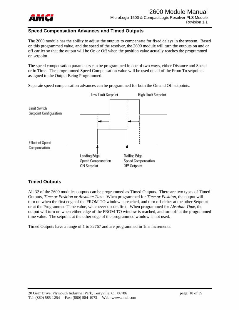
Speed Compensation Advances and Timed Outputs The 2600 module has the ability to adjust the outputs to compensate for fixed delays in the system. Based on this programmed value, and the speed of the resolver, the 2600 module will turn the outputs on and or off earlier so that the output will be On or Off when the position value actually reaches the programmed on setpoint. The speed compensation parameters can be programmed in one of two ways, either Distance and Speed or in Time. The programmed Speed Compensation value will be used on all of the From To setpoints assigned to the Output Being Programmed. Separate speed compensation advances can be programmed for both the On and Off setpoints.
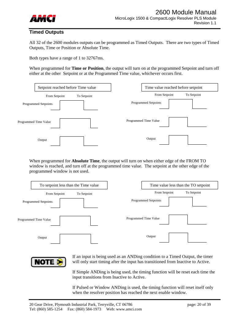
Timed Outputs All 32 of the 2600 modules outputs can be programmed as Timed Outputs. There are two types of Timed Outputs, Time or Position or Absolute Time. When programmed for Time or Position, the output will turn on when the first edge of the FROM TO window is reached, and turn off either at the other Setpoint or at the Programmed Time value, whichever occurs first. When programmed for Absolute Time, the output will turn on when either edge of the FROM TO window is reached, and turn off at the programmed time value. The setpoint at the other edge of the programmed window is not used. Timed Outputs have a range of 1 to 32767 and are programmed in 1ms increments.

20 Gear Drive, Plymouth Industrial Park, Terryville, CT 06786 page: 19 of 39 Tel: (860) 585-1254 Fax: (860) 584-1973 Web: www.amci.com
2600 Module Manual MicroLogix 1500 & CompactLogix Resolver PLS Module
Revision 1.1
Output Being Programmed: This parameter defines to what output the remaining Speed Compensation and Timed Output parameters are being assigned to. 2611 module range: 0 to 15 2612 module range: 0 to 23 2613 module range: 0 to 31
Advance based on Distance (in counts) and Speed (in RPM)
Lead Position Distance: This parameter defines the distance, in counts, to advance the beginning, the OFF to ON edge, of the From To Setpoint window. This parameter has a range of (0 to Resolver Rollover Position)
Lead Speed RPM: This parameter sets the speed at which the resolver must be turning in order to compensate by Lead Position Distance. This parameter has a range of 0 to 32767 and can only be equal to zero when the Lead Position Distance is equal to 0.
Trailing Position Distance: This parameter defines the distance, in counts, to advance the ending, the
ON to OFF edge, of the From To Setpoint window. This parameter has a range of (0 to Resolver Rollover Position)
Trailing Speed RPM: This parameter sets the speed at which the resolver must be turning in order to
compensate by Trailing Position Distance. This parameter has a range of 0 to 32767 and can only be equal to zero when the Trailing Position Distance is equal to 0.
Advance based on Time (in milliseconds)
Lead Advance Time: This parameter defines the time to advance the beginning, the OFF to ON edge, of a setpoint window for Speed Compensation. This parameter has a range of 0 to 32767.
Trail Advance Time: This parameter defines the time to advance the ending, the ON to OFF edge, of
a setpoint window for Speed Compensation. This parameter has a range of 0 to 32767.
The 2600 module calculates how much an output needs to be advanced, in counts, based on the programmed advanced values and the rotating speed of the resolver. Unpredictable operations will occur if this number of counts exceeds the programmed Rollover Count Value. The 2600 module will set input word 0 bit 10, the RPM Clamped bit, to indicate to the PLC that the advanced output may not be firing correctly.
20 Gear Drive, Plymouth Industrial Park, Terryville, CT 06786 page: 20 of 39 Tel: (860) 585-1254 Fax: (860) 584-1973 Web: www.amci.com
2600 Module Manual MicroLogix 1500 & CompactLogix Resolver PLS Module
Revision 1.1
Timed Outputs All 32 of the 2600 modules outputs can be programmed as Timed Outputs. There are two types of Timed Outputs, Time or Position or Absolute Time. Both types have a range of 1 to 32767ms. When programmed for Time or Position, the output will turn on at the programmed Setpoint and turn off either at the other Setpoint or at the Programmed Time value, whichever occurs first. When programmed for Absolute Time, the output will turn on when either edge of the FROM TO window is reached, and turn off at the programmed time value. The setpoint at the other edge of the programmed window is not used.
From Setpoint To Setpoint
Programmed Setpoints
Output
Programmed Time Value
From Setpoint To Setpoint
Programmed Setpoints
Output
Programmed Time Value
Setpoint reached before Time value Time value reached before setpoint
From Setpoint To Setpoint
Programmed Setpoints
Output
Programmed Time Value
From Setpoint To Setpoint
Programmed Setpoints
Output
Programmed Time Value
To setpoint less than the Time value Time value less than the TO setpoint
If an input is being used as an ANDing condition to a Timed Output, the timer will only start timing after the input has transitioned from Inactive to Active. If Simple ANDing is being used, the timing function will be reset each time the input transitions from Inactive to Active. If Pulsed or Window ANDing is used, the timing function will reset itself only when the resolver position has reached the next enable window.

20 Gear Drive, Plymouth Industrial Park, Terryville, CT 06786 page: 21 of 39 Tel: (860) 585-1254 Fax: (860) 584-1973 Web: www.amci.com
2600 Module Manual MicroLogix 1500 & CompactLogix Resolver PLS Module
Revision 1.1
ANDing Functions The 2600 module provides the ability to condition when the outputs fire by ANDing the output with an input(s), with the RPM value, or both. It is also possible to combine two or more ANDing types and functions together. There are three types of Input ANDing. They are Simple ANDing, Pulse ANDing, and Window ANDing. Simple ANDing When using Simple ANDing, the output will only fire when the corresponding input is active.
Pulse ANDing When using Pulse ANDing, the output will fire once if the corresponding input becomes active within the programmed FROM TO range, and will remain active until the TO setpoint is reached. If multiple FROM TO setpoints have been programmed, then the input must become active in each of the FROM TO setpoints.
From Setpoint To Setpoint
Programmed Setpoints
Output
Input
From Setpoint To Setpoint
Programmed Setpoints
Output
Input

20 Gear Drive, Plymouth Industrial Park, Terryville, CT 06786 page: 22 of 39 Tel: (860) 585-1254 Fax: (860) 584-1973 Web: www.amci.com
2600 Module Manual MicroLogix 1500 & CompactLogix Resolver PLS Module
Revision 1.1
Window ANDing When using Window ANDing, for the output to fire, the corresponding input must be active at some point within the Enable Window.
For all three Input ANDing types, the Input Parameter has the following ranges.
2611 module range: 0 to 15 2612 module range: 0 to 23 2613 module range: 0 to 31
For the Window ANDing, the Enable Window FROM and TO setpoints have a range of (0 to Resolver Rollover Position) RPM ANDing
This function consists of two words, a RPM Enable Low Limit and a RPM Enable High Limit. When used, the corresponding output will only fire when the velocity value is either between or outside of the programmed ranges. If the low limit is less than the high limit, then the output will be on when the velocity is between the two setpoints and off at all other speeds. If the low limit is greater than the high limit, then the output will be off when the velocity is between the two setpoints and on at all other speeds. The RPM Low and High Limits both have a range of (-32768 to 32767) RPM ANDing can be combined with any of the other ANDing types listed above.
Unpredictable operations will occur if the Enable Window is contained within or overlaps any portion of the programmed FROM TO setpoints. Simple or Pulse ANDing should be used in these cases.

20 Gear Drive, Plymouth Industrial Park, Terryville, CT 06786 page: 23 of 39 Tel: (860) 585-1254 Fax: (860) 584-1973 Web: www.amci.com
2600 Module Manual MicroLogix 1500 & CompactLogix Resolver PLS Module
Revision 1.1
Limit Switch Shifting Data The 2600 does not necessarily fire its outputs based on the Scaled Machine Position. Each of the Limit Switch outputs instead maintains its own internal position that can be offset or adjusted based on the state of the module’s inputs. The Limit Switch Shifting parameters allow you to assign which of the 2600 module’s inputs will control these shifting functions.
Output Being Programmed: This parameter defines to what output the remaining Limit Switch Shifting
parameters are being assigned to. This parameter has the following ranges 2611 module range: 0 to 15 2612 module range: 0 to 23 2613 module range: 0 to 31
Limit Preset Input Number: When this input becomes active, the internal position that the Output Being
Programmed is using will be set to the Limit Preset Value. This parameter has the following ranges. 2611 module range: 0 to 15 2612 module range: 0 to 23 2613 module range: 0 to 31
Limit Preset Value: This is the value to which the Internal Limit Switch Position will be set when the
Limit Preset Input becomes active. This parameter has a range of (0 to Resolver Rollover Position) Default Value = 0
Limit Nudge Up Input Number: When this input becomes active, the internal position that the Output Being Programmed is using will be increased by the Nudge Up Value. The Limit Preset Value will also be increased by this amount. This parameter has the following ranges. 2611 module range: 0 to 15 2612 module range: 0 to 23 2613 module range: 0 to 31
Limit Nudge Up Value: This is the value by which the Internal Limit Switch Position and the Limit Preset
Value will be increased when the Nudge Up Input becomes active. This parameter has a range of (0 to Resolver Rollover Position) Default Value = 0
The Nudge Up parameter makes the output turn on earlier in the turn, and the Nudge Down parameter makes the output turn on later in the turn. For example, assume that you have programmed an output to turn on at 100 degrees and off at 150 degrees, and that your Nudge Up value is equal to 10. The output will fire from 90 to 140 degrees after the first inactive to active transition of the Nudge Up Input, and from 80 to 130 on the second inactive to active transition of the Nudge Up Input.

20 Gear Drive, Plymouth Industrial Park, Terryville, CT 06786 page: 24 of 39 Tel: (860) 585-1254 Fax: (860) 584-1973 Web: www.amci.com
2600 Module Manual MicroLogix 1500 & CompactLogix Resolver PLS Module
Revision 1.1
Limit Nudge Down Input Number: When this input becomes active, the internal position that the Output Being Programmed is using will be decreased by the Nudge Down Value. The Limit Preset Value will also be decreased by this amount. This parameter has the following ranges. 2611 module range: 0 to 15 2612 module range: 0 to 23 2613 module range: 0 to 31
Limit Nudge Down Value: This is the value by which the Internal Limit Switch Position and the Limit
Preset Value will be decreased when the Nudge Down Input becomes active. This parameter has a range of (0 to Resolver Rollover Position) Default Value = 0
Forcing, Virtual Inputs, & Get Attributes Data These functions are all sent to the 2600 module with one programming block. The first is the ability to Force both the outputs and the inputs ON or OFF. This function is useful for testing the wiring of your system, or for giving the PLC direct control over the 2600 module’s outputs. The second is the control of the 2600 modules Virtual Inputs, which are always numbered 0 to 15 and have no physical presence. That is, to activate the input, the ladder logic program must set a bit in the output registers assigned to the 2600 module. These bits exist in this programming block. The third is the ability to read back additional information from the 2600 module. This includes internal Preset values, the state of the outputs before they have been modified by the ANDing or Forcing functions, and the resolver position where the inputs transition both on and off. Override Output Enable Bits: Setting any of the bits in this word cause the corresponding Physical Output
to be assigned to the state specified by the bits in the Override Output Value word. Bit 0 = Output 16, Bit 1 = Output 17 … Bit 15 = Output 31.
Override Output Value: The bits in this word are combined with the bits in the Override Output Enable Bits to Force the Physical Inputs on or off. Bit 0 = Output 16, Bit 1 = Output 17 … Bit 15 = Output 31. For example,
Override Output
Enable Bit Override
Output Value Result
0 0 Output fires based on the programmed On / Off setpoints and ANDing conditions.
0 1 Output fires based on the programmed On / Off setpoints and ANDing conditions.
1 0 Output Always OFF 1 1 Output Always ON

20 Gear Drive, Plymouth Industrial Park, Terryville, CT 06786 page: 25 of 39 Tel: (860) 585-1254 Fax: (860) 584-1973 Web: www.amci.com
2600 Module Manual MicroLogix 1500 & CompactLogix Resolver PLS Module
Revision 1.1
Override Input Enable Bits: Setting any of the bits in this word cause the corresponding Physical Input to be assigned to the state specified by the bits in the Override Input Value word. Bit 0 = Input 16, Bit 1 = Input 17 … Bit 15 = Input 31.
Override Input Value: The bits in this word are combined with the bits in the Override Input Enable Bits to simulate the Physical Inputs on or off. Bit 0 = Input 16, Bit 1 = Input 17 … Bit 15 = Input 31. For Example
Override Input Enable Bit
Override Input Value Result
0 0 The state of the Input on the connector is used by the 2600 module.
0 1 The state of the Input on the connector is used by the 2600 module.
1 0 The 2600 module considers the corresponding input to be inactive.
1 1 The 2600 module considers the corresponding input to be active. Virtual Inputs: These bits give the PLC control over the 2600 module’s Virtual Inputs, which are defined
as inputs 0 to 15. The virtual inputs have no physical presence. These the bits, and therefore the state of the inputs, are directly controlled by the ladder logic program Bit 0 = Input 0, Bit 1 = Input 1 … Bit 15 = Input 15.
Get Attributes: The value entered in these words controls what data is transferred to input words 6 and 7.
Attribute
Num
ber
Attribute D
ata
Displayed in Status Word 0 of
PLC Input Registers
Displayed in Word 6 of PLC Input Registers
Displayed in Word 7 of PLC Input Registers
Bits 6,5 Bits 4..0
0 Not used 00 00 2600 modification read from the module;
Firmware version (MSB) + revision (LSB) number;
1 Not used 00 01 Physical Output state without inversion or override;
Physical Input state after applying override and inversion;
2 Not used 00 02 Virtual Outputs calculated from the Limit Switch Setpoints;
Physical Outputs calculated from the Limit Switch Setpoints;
3 Not used 00 03 The last valid position accounting for the programmed Resolver Rollover Counts;
12-bit Resolver Position from the front connector;
4 Not used 00 04 +/- signed Turn Count MSW (1000s places);
+/- signed Turn Count LSW (1s, 10s and 100s places);
5 Not used 00 05 =0 (reserved); =0 (reserved);
6
32 00 06 Global Preset Value; Global Offset Value;
Output xx
(0..31) 10 xx Preset Value for Output Point xx; Offset Value for Output Point xx;
7 Input xx (0..31)
11 xx (Rising) Position at which the Input Point xx changed from 0 to 1;
(Falling) Position at which the Input Point xx changed from 1 to 0;
20 Gear Drive, Plymouth Industrial Park, Terryville, CT 06786 page: 26 of 39 Tel: (860) 585-1254 Fax: (860) 584-1973 Web: www.amci.com
2600 Module Manual MicroLogix 1500 & CompactLogix Resolver PLS Module
Revision 1.1
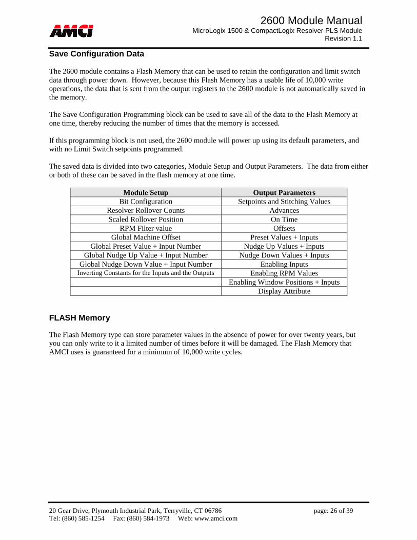
Save Configuration Data The 2600 module contains a Flash Memory that can be used to retain the configuration and limit switch data through power down. However, because this Flash Memory has a usable life of 10,000 write operations, the data that is sent from the output registers to the 2600 module is not automatically saved in the memory. The Save Configuration Programming block can be used to save all of the data to the Flash Memory at one time, thereby reducing the number of times that the memory is accessed. If this programming block is not used, the 2600 module will power up using its default parameters, and with no Limit Switch setpoints programmed. The saved data is divided into two categories, Module Setup and Output Parameters. The data from either or both of these can be saved in the flash memory at one time.
Module Setup Output Parameters Bit Configuration Setpoints and Stitching Values
Resolver Rollover Counts Advances Scaled Rollover Position On Time
RPM Filter value Offsets Global Machine Offset Preset Values + Inputs
Global Preset Value + Input Number Nudge Up Values + Inputs Global Nudge Up Value + Input Number Nudge Down Values + Inputs
Global Nudge Down Value + Input Number Enabling Inputs Inverting Constants for the Inputs and the Outputs Enabling RPM Values
Enabling Window Positions + Inputs Display Attribute
FLASH Memory The Flash Memory type can store parameter values in the absence of power for over twenty years, but you can only write to it a limited number of times before it will be damaged. The Flash Memory that AMCI uses is guaranteed for a minimum of 10,000 write cycles.
20 Gear Drive, Plymouth Industrial Park, Terryville, CT 06786 page: 27 of 39 Tel: (860) 585-1254 Fax: (860) 584-1973 Web: www.amci.com
2600 Module Manual MicroLogix 1500 & CompactLogix Resolver PLS Module
Revision 1.1
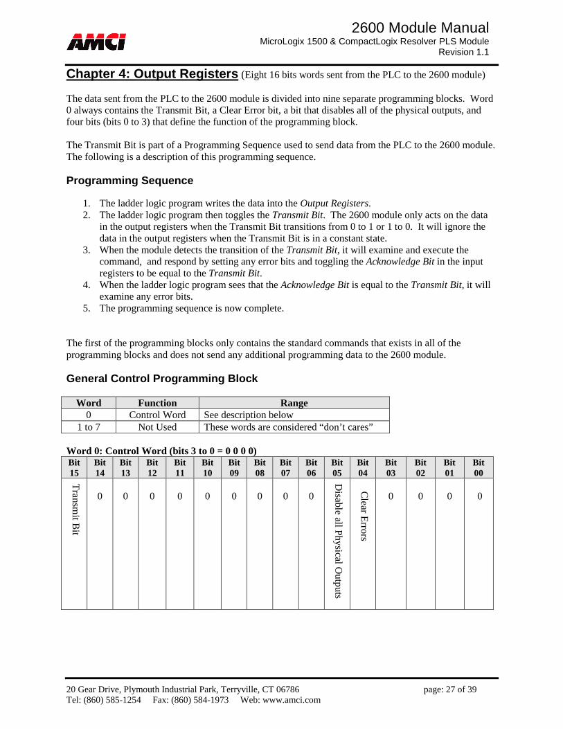
Chapter 4: Output Registers (Eight 16 bits words sent from the PLC to the 2600 module) The data sent from the PLC to the 2600 module is divided into nine separate programming blocks. Word 0 always contains the Transmit Bit, a Clear Error bit, a bit that disables all of the physical outputs, and four bits (bits 0 to 3) that define the function of the programming block. The Transmit Bit is part of a Programming Sequence used to send data from the PLC to the 2600 module. The following is a description of this programming sequence. Programming Sequence
1. The ladder logic program writes the data into the Output Registers. 2. The ladder logic program then toggles the Transmit Bit. The 2600 module only acts on the data
in the output registers when the Transmit Bit transitions from 0 to 1 or 1 to 0. It will ignore the data in the output registers when the Transmit Bit is in a constant state.
3. When the module detects the transition of the Transmit Bit, it will examine and execute the command, and respond by setting any error bits and toggling the Acknowledge Bit in the input registers to be equal to the Transmit Bit.
4. When the ladder logic program sees that the Acknowledge Bit is equal to the Transmit Bit, it will examine any error bits.
5. The programming sequence is now complete. The first of the programming blocks only contains the standard commands that exists in all of the programming blocks and does not send any additional programming data to the 2600 module. General Control Programming Block
Word Function Range 0 Control Word See description below
1 to 7 Not Used These words are considered “don’t cares” Word 0: Control Word (bits 3 to 0 = 0 0 0 0) Bit 15
Bit 14
Bit 13
Bit 12
Bit 11
Bit 10
Bit 09
Bit 08
Bit 07
Bit 06
Bit 05
Bit 04
Bit 03
Bit 02
Bit 01
Bit 00
Transm
it Bit
0
0
0
0
0
0
0
0
0
Disable all P
hysical Outputs
Clear E
rrors
0
0
0
0

20 Gear Drive, Plymouth Industrial Park, Terryville, CT 06786 page: 28 of 39 Tel: (860) 585-1254 Fax: (860) 584-1973 Web: www.amci.com
2600 Module Manual MicroLogix 1500 & CompactLogix Resolver PLS Module
Revision 1.1
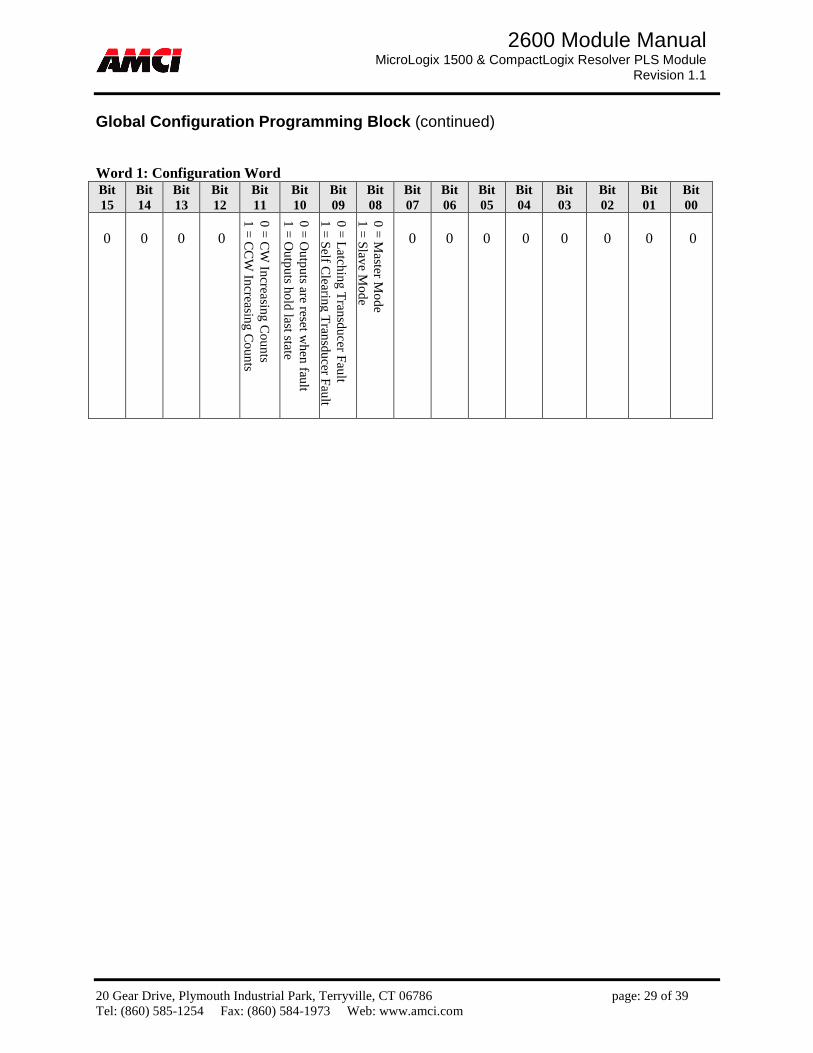
Global Configuration Programming Block
Word Function Range 0 Control Word See description below 1 Configuration Bits See description below
2 Resolver Rollover
Counts 1 to 4095
3 Resolver Rollover
Position 1 to the Resolver Rollover Counts
4 Scaled Machine
Offset (–Resolver Rollover Position to + Resolver Rollover Position)
5 RPM Filter 0 to 65535 (0 to FFFFh)
6 Inverted Physical Outputs Constant
0 to FFFFh Bit 0 controls output 16, bit 1 controls output 17 … bit 15 controls output 31
7 Inverted Physical Inputs Constant
0 to FFFFh Bit 0 controls input 16, bit 1 controls input 17 … bit 15 controls input 31
Word 0: Control Word (bits 3 to 0 = 0 0 0 1) Bit 15
Bit 14
Bit 13
Bit 12
Bit 11
Bit 10
Bit 09
Bit 08
Bit 07
Bit 06
Bit 05
Bit 04
Bit 03
Bit 02
Bit 01
Bit 00
Tran
smit B
it
Ap
ply W
ord
7 as th
e Inverted
Ph
ysical Inp
ut C
on
stant
Ap
ply W
ord
6 as th
e Inverted
Ph
ysical Ou
tpu
ts Co
nstan
t
Ap
ply W
ord
5 as th
e RP
M
Filter
Ap
ply W
ord
4 as th
e Scaled
M
achin
e Offset
Ap
ply W
ord
3 as R
esolver
Ro
llover P
ositio
n
Ap
ply W
ord
2 as R
esolver
Ro
llover C
ou
nts
Ap
ply W
ord
1 as C
on
figuration
B
its
0
Ap
ply F
actory In
itialization
C
on
stants
Disab
le all Ph
ysical Ou
tpu
ts
Clear E
rrors
0
0
0
1
Control Word bits 8 to 14 control what data is being programmed in output words 1 to 7. If these bits are not set, the data in the corresponding output word will be ignored. For example, the configuration bits in Word 1 will only be read and acted on when bit 8 is set.
The Apply Factory Initialization Constants bit returns all of the 2600 module’s parameters back to their default values. This includes a Rollover Count value of 4095, a Rollover position value of 359, resetting all of the Preset and Offset Values to zero, and all of the inputs and Limit Switch Outputs not used.
20 Gear Drive, Plymouth Industrial Park, Terryville, CT 06786 page: 29 of 39 Tel: (860) 585-1254 Fax: (860) 584-1973 Web: www.amci.com
2600 Module Manual MicroLogix 1500 & CompactLogix Resolver PLS Module
Revision 1.1
Global Configuration Programming Block (continued) Word 1: Configuration Word Bit 15
Bit 14
Bit 13
Bit 12
Bit 11
Bit 10
Bit 09
Bit 08
Bit 07
Bit 06
Bit 05
Bit 04
Bit 03
Bit 02
Bit 01
Bit 00
0
0
0
0
0 =
CW
Increasin
g C
ou
nts
1 =
CC
W In
creasing
Co
un
ts
0 =
Ou
tpu
ts are reset wh
en fau
lt 1
= O
utp
uts ho
ld last state
0 =
Latch
ing T
ransdu
cer Fau
lt 1
= S
elf Clearin
g T
ransdu
cer Fau
lt
0 =
Master M
od
e 1
= S
lave Mo
de
0
0
0
0
0
0
0
0
20 Gear Drive, Plymouth Industrial Park, Terryville, CT 06786 page: 30 of 39 Tel: (860) 585-1254 Fax: (860) 584-1973 Web: www.amci.com
2600 Module Manual MicroLogix 1500 & CompactLogix Resolver PLS Module
Revision 1.1
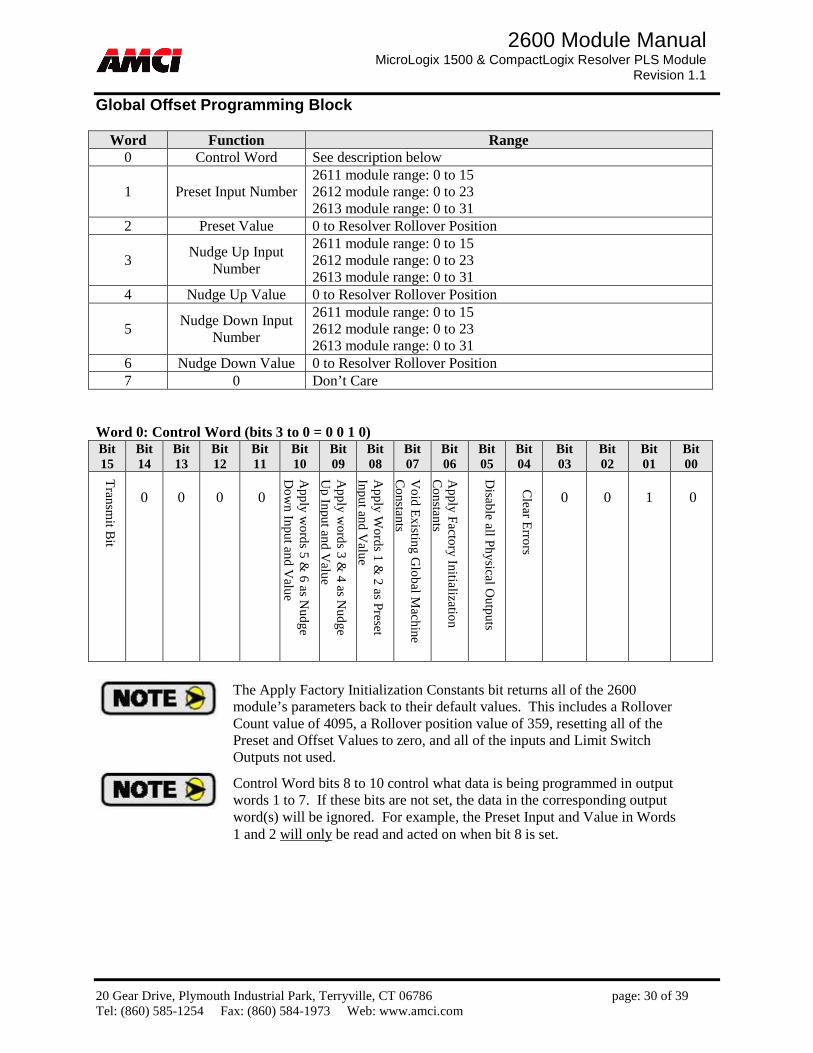
Global Offset Programming Block
Word Function Range 0 Control Word See description below
1 Preset Input Number 2611 module range: 0 to 15 2612 module range: 0 to 23 2613 module range: 0 to 31
2 Preset Value 0 to Resolver Rollover Position
3 Nudge Up Input
Number
2611 module range: 0 to 15 2612 module range: 0 to 23 2613 module range: 0 to 31
4 Nudge Up Value 0 to Resolver Rollover Position
5 Nudge Down Input
Number
2611 module range: 0 to 15 2612 module range: 0 to 23 2613 module range: 0 to 31
6 Nudge Down Value 0 to Resolver Rollover Position 7 0 Don’t Care
Word 0: Control Word (bits 3 to 0 = 0 0 1 0) Bit 15
Bit 14
Bit 13
Bit 12
Bit 11
Bit 10
Bit 09
Bit 08
Bit 07
Bit 06
Bit 05
Bit 04
Bit 03
Bit 02
Bit 01
Bit 00
Tran
smit B
it
0
0
0
0
Ap
ply w
ord
s 5 &
6 as Nu
dg
e D
ow
n In
put an
d Valu
e
Ap
ply w
ord
s 3 &
4 as Nu
dg
e U
p In
put an
d V
alue
Ap
ply W
ord
s 1 &
2 as P
reset In
pu
t and
Valu
e
Vo
id E
xisting
Glo
bal M
achine
Co
nstan
ts
Ap
ply F
actory In
itialization
C
on
stants
Disab
le all Ph
ysical Ou
tpu
ts
Clear E
rrors
0
0
1
0
Control Word bits 8 to 10 control what data is being programmed in output words 1 to 7. If these bits are not set, the data in the corresponding output word(s) will be ignored. For example, the Preset Input and Value in Words 1 and 2 will only be read and acted on when bit 8 is set.
The Apply Factory Initialization Constants bit returns all of the 2600 module’s parameters back to their default values. This includes a Rollover Count value of 4095, a Rollover position value of 359, resetting all of the Preset and Offset Values to zero, and all of the inputs and Limit Switch Outputs not used.

20 Gear Drive, Plymouth Industrial Park, Terryville, CT 06786 page: 31 of 39 Tel: (860) 585-1254 Fax: (860) 584-1973 Web: www.amci.com
2600 Module Manual MicroLogix 1500 & CompactLogix Resolver PLS Module
Revision 1.1
Limit Switch Programming Block
Word Function Range 0 Control Word See description below
1 Output Being Programmed
2611 module range: 0 to 15 2612 module range: 0 to 23 2613 module range: 0 to 31
2 Limit Offset –Rollover Position to + Rollover Position 3 Output Setpoint 0 to 15 4 From Position 0 to Resolver Rollover Position 5 To Position 0 to Resolver Rollover Position 6 On Stitch Distance (1 to ((To Position – From Position) - 1) / 2) 7 Off Stitch Distance (1 to ((To Position – From Position) – 2 * On Stitch Distance)
Word 0: Control Word (bits 3 to 0 = 0 0 1 1) Bit 15
Bit 14
Bit 13
Bit 12
Bit 11
Bit 10
Bit 09
Bit 08
Bit 07
Bit 06
Bit 05
Bit 04
Bit 03
Bit 02
Bit 01
Bit 00
Tran
smit B
it
0
0
0
0
Ap
ply W
ord
s 3 to 7
as Stitch
ing
L
imit S
witch
Param
eters
Ap
ply W
ord
s 3, 4
, and 5
as L
imit S
witch
Param
eters
Ap
ply W
ord
2 as th
e Lim
it O
ffset
Delete th
e Setp
oin
t defin
ed in
o
utp
ut w
ord 3
Vo
id th
e setup
for ou
tpu
t d
efined
in ou
tput w
ord
1
Disab
le all Ph
ysical Ou
tpu
ts
Clear E
rrors
0
0
1
1
Control Word bits 8 to 10 control what data is being programmed in output words 1 to 7. If these bits are not set, the data in the corresponding output word will be ignored. For example, the Limit Switch Parameters in Word 3, 4, and 5 will only be read and acted on when bit 9 is set.
Setting both Control Word bits 9 and 10 at the same time will result in the Stitching Type output being programmed. No error bit will be set.
The Limit Switch Output will be on for the entire rotation of the resolver if the From and To setpoints are equal to each other.

20 Gear Drive, Plymouth Industrial Park, Terryville, CT 06786 page: 32 of 39 Tel: (860) 585-1254 Fax: (860) 584-1973 Web: www.amci.com
2600 Module Manual MicroLogix 1500 & CompactLogix Resolver PLS Module
Revision 1.1
Speed Compensation Advances and Timed Outputs Programming Block Word Function Range Function Range
0 Control Word See description below Control
Word See description below
1 Output Being Programmed
2611 module range: 0 to 15 2612 module range: 0 to 23 2613 module range: 0 to 31
Output Being Programmed
2611 module range: 0 to 15 2612 module range: 0 to 23 2613 module range: 0 to 31
2 Lead Position
Distance 0 to Resolver Rollover Position
Lead Advance
Time 0 to 32767 milliseconds
3 Lead Speed
RPM 0 to 32767
0 Must Be Zero
4 Trail Position
Distance 0 to Resolver Rollover Position
Trail Advance
Time 0 to 32767 milliseconds
5 Trail Speed
RPM 0 to 32767
0 Must Be Zero
6 Time Output 1 to 32767 millisconds Time Output 1 to 32767 milliseconds 7 Not Used 0 Not Used 0
Word 0: Control Word (bits 3 to 0 = 0 1 0 0) Bit 15
Bit 14
Bit 13
Bit 12
Bit 11
Bit 10
Bit 09
Bit 08
Bit 07
Bit 06
Bit 05
Bit 04
Bit 03
Bit 02
Bit 01
Bit 00
Tran
smit B
it
0
0
0
Ap
ply W
ord
6 as an
Ab
solu
te On
T
ime T
imed
Ou
tput
Ap
ply W
ord
6 as a T
ime or P
ositio
n
Tim
ed O
utp
ut
Ap
ply W
ord
s 2 to 5
as Ad
vance T
ime in
milliseco
nd
s
Ap
ply W
ord
2 to
5 as Ad
vance
Distan
ce and
RP
M
De
lete a
ll of th
e Advan
ce a
nd T
imed
output
pa
ram
ete
rs for th
e ou
tput d
efine
d in w
ord
1.
Vo
id the
setup, in
cluding the
on/o
ff setp
oints, fo
r the
outpu
t de
fined in
outp
ut wo
rd 1
Disab
le all Ph
ysical Ou
tpu
ts
Clear E
rrors
0
1
0
0
Control Word bits 8 to 11 control what data is being programmed in output words 1 to 7. If these bits are not set, the data in the corresponding output word(s) will be ignored. For example, the data in Word 2 through 5 will only be read and acted on as the Limit Switch Advances in Milliseconds when bit 9 is set.
Setting both Control Word bits 8 and 9 is not allowed and will cause the module to generate a Programming Error. If both bits 10 and 11 are set, the Timed Output will be programmed as an Absolute On Time Timed Output.
Speed Compensation Advances Programmed as Distance and RPM
and Timed Outputs
Speed Compensation Advances Programmed in Milliseconds and
Timed Outputs
20 Gear Drive, Plymouth Industrial Park, Terryville, CT 06786 page: 33 of 39 Tel: (860) 585-1254 Fax: (860) 584-1973 Web: www.amci.com
2600 Module Manual MicroLogix 1500 & CompactLogix Resolver PLS Module
Revision 1.1
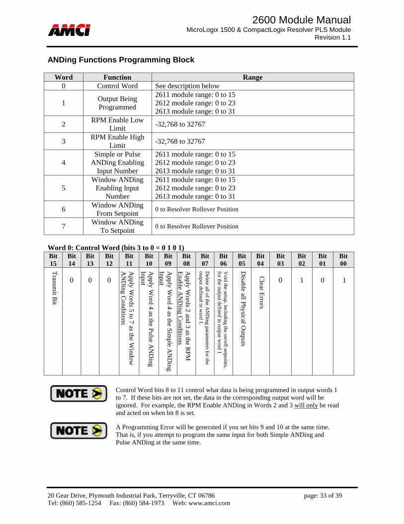
ANDing Functions Programming Block
Word Function Range 0 Control Word See description below
1 Output Being Programmed
2611 module range: 0 to 15 2612 module range: 0 to 23 2613 module range: 0 to 31
2 RPM Enable Low
Limit -32,768 to 32767
3 RPM Enable High
Limit -32,768 to 32767
4 Simple or Pulse
ANDing Enabling Input Number
2611 module range: 0 to 15 2612 module range: 0 to 23 2613 module range: 0 to 31
5 Window ANDing
Enabling Input Number
2611 module range: 0 to 15 2612 module range: 0 to 23 2613 module range: 0 to 31
6 Window ANDing
From Setpoint 0 to Resolver Rollover Position
7 Window ANDing
To Setpoint 0 to Resolver Rollover Position
Word 0: Control Word (bits 3 to 0 = 0 1 0 1) Bit 15
Bit 14
Bit 13
Bit 12
Bit 11
Bit 10
Bit 09
Bit 08
Bit 07
Bit 06
Bit 05
Bit 04
Bit 03
Bit 02
Bit 01
Bit 00
Tran
smit B
it
0
0
0
Ap
ply W
ord
s 5 to 7
as the W
ind
ow
A
ND
ing
Co
nd
ition
s
Ap
ply W
ord
4 as th
e Pu
lse AN
Din
g
Inp
ut
Ap
ply W
ord
4 as th
e Sim
ple A
ND
ing
In
pu
t
Ap
ply W
ord
s 2 an
d 3 as th
e RP
M
En
able A
ND
ing
Co
nd
ition
s
De
lete a
ll of th
e AN
Ding
pa
ram
eters fo
r the
output d
efin
ed in w
ord
1.
Vo
id the
setup, in
cluding the
on/o
ff setp
oints, fo
r the
outpu
t de
fined in
outp
ut wo
rd 1
Disab
le all Ph
ysical Ou
tpu
ts
Clear E
rrors
0
1
0
1
Control Word bits 8 to 11 control what data is being programmed in output words 1 to 7. If these bits are not set, the data in the corresponding output word will be ignored. For example, the RPM Enable ANDing in Words 2 and 3 will only be read and acted on when bit 8 is set.
A Programming Error will be generated if you set bits 9 and 10 at the same time. That is, if you attempt to program the same input for both Simple ANDing and Pulse ANDing at the same time.

20 Gear Drive, Plymouth Industrial Park, Terryville, CT 06786 page: 34 of 39 Tel: (860) 585-1254 Fax: (860) 584-1973 Web: www.amci.com
2600 Module Manual MicroLogix 1500 & CompactLogix Resolver PLS Module
Revision 1.1
Limit Switch Shifting Programming Block
Word Function Range 0 Control Word See description below
1 Output Being Programmed
2611 module range: 0 to 15 2612 module range: 0 to 23 2613 module range: 0 to 31
2 Limit Preset Input
Number
2611 module range: 0 to 15 2612 module range: 0 to 23 2613 module range: 0 to 31
3 Limit Preset Value 0 to Resolver Rollover Position
4 Limit Nudge Up Input Number
2611 module range: 0 to 15 2612 module range: 0 to 23 2613 module range: 0 to 31
5 Limit Nudge Up
Value 0 to Resolver Rollover Position
6 Limit Nudge Down
Input Number
2611 module range: 0 to 15 2612 module range: 0 to 23 2613 module range: 0 to 31
7 Limit Nudge Down
Value 0 to Resolver Rollover Position
Word 0: Control Word (bits 3 to 0 = 0 1 1 0) Bit 15
Bit 14
Bit 13
Bit 12
Bit 11
Bit 10
Bit 09
Bit 08
Bit 07
Bit 06
Bit 05
Bit 04
Bit 03
Bit 02
Bit 01
Bit 00
Tran
smit B
it
0
0
0
0
Ap
ply W
ord
s 6 an
d 7 as L
imit N
ud
ge
Do
wn
Param
eters
Ap
ply W
ord
s 4 an
d 5 as L
imit N
ud
ge
Up
Param
eters
Ap
ply W
ord
s 2 an
d 3 as th
e Limit
Preset P
arameters
De
lete a
ll of th
e Limit S
witch
Sh
ifting
pa
ram
ete
rs for th
e ou
tput d
efine
d in w
ord
1.
Vo
id the
setup, in
cluding the
on/o
ff setp
oints, fo
r the
outpu
t de
fined in
outp
ut wo
rd 1
Disab
le all Ph
ysical Ou
tpu
ts
Clear E
rrors
0
1
1
0
Control Word bits 8 to 10 control what data is being programmed in output words 1 to 7. If these bits are not set, the data in the corresponding output word will be ignored. For example, the Limit Preset Parameters in Words 2 and 3 will only be read and acted on when bit 8 is set.
The Nudge Up parameter makes the output turn on earlier in the turn, and the Nudge Down parameter makes the output turn on later in the turn. For example, assume that you have programmed an output to turn on at 100 degrees and off at 150 degrees, and that your Nudge Up value is equal to 10. The output will fire from 90 to 140 degrees after the first inactive to active transition of the Nudge Up Input, and from 80 to 130 on the second inactive to active transition of the Nudge Up Input.
20 Gear Drive, Plymouth Industrial Park, Terryville, CT 06786 page: 35 of 39 Tel: (860) 585-1254 Fax: (860) 584-1973 Web: www.amci.com
2600 Module Manual MicroLogix 1500 & CompactLogix Resolver PLS Module
Revision 1.1
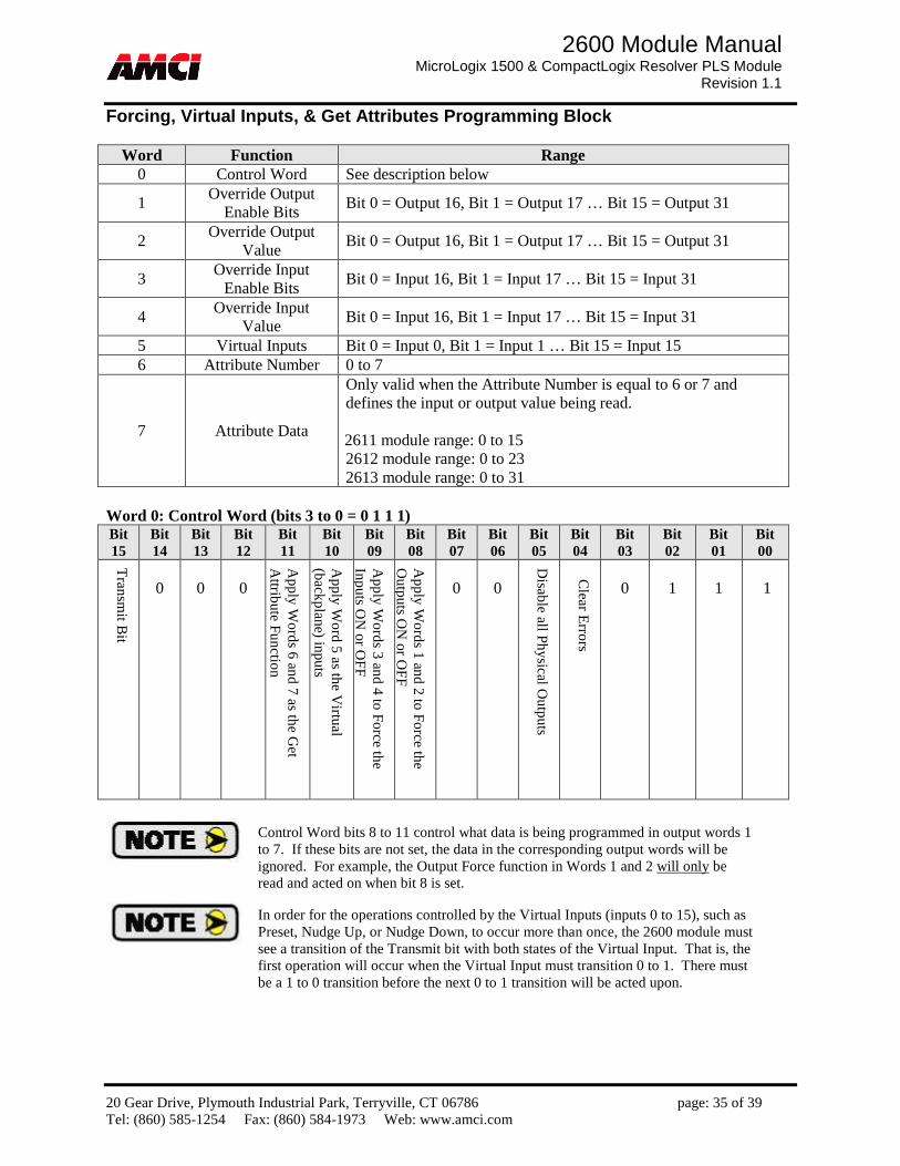
Forcing, Virtual Inputs, & Get Attributes Programming Block
Word Function Range 0 Control Word See description below
1 Override Output
Enable Bits Bit 0 = Output 16, Bit 1 = Output 17 … Bit 15 = Output 31
2 Override Output
Value Bit 0 = Output 16, Bit 1 = Output 17 … Bit 15 = Output 31
3 Override Input
Enable Bits Bit 0 = Input 16, Bit 1 = Input 17 … Bit 15 = Input 31
4 Override Input
Value Bit 0 = Input 16, Bit 1 = Input 17 … Bit 15 = Input 31
5 Virtual Inputs Bit 0 = Input 0, Bit 1 = Input 1 … Bit 15 = Input 15 6 Attribute Number 0 to 7
7 Attribute Data
Only valid when the Attribute Number is equal to 6 or 7 and defines the input or output value being read. 2611 module range: 0 to 15 2612 module range: 0 to 23 2613 module range: 0 to 31
Word 0: Control Word (bits 3 to 0 = 0 1 1 1) Bit 15
Bit 14
Bit 13
Bit 12
Bit 11
Bit 10
Bit 09
Bit 08
Bit 07
Bit 06
Bit 05
Bit 04
Bit 03
Bit 02
Bit 01
Bit 00
Tran
smit B
it
0
0
0
Ap
ply W
ord
s 6 an
d 7 as th
e Get
Attrib
ute F
un
ction
Ap
ply W
ord
5 as th
e Virtu
al (b
ackplan
e) inpu
ts
Ap
ply W
ord
s 3 an
d 4 to
Fo
rce the
Inp
uts O
N o
r OF
F
Ap
ply W
ord
s 1 an
d 2 to
Fo
rce the
Ou
tpu
ts ON
or O
FF
0
0
Disab
le all Ph
ysical Ou
tpu
ts
Clear E
rrors
0
1
1
1
Control Word bits 8 to 11 control what data is being programmed in output words 1 to 7. If these bits are not set, the data in the corresponding output words will be ignored. For example, the Output Force function in Words 1 and 2 will only be read and acted on when bit 8 is set.
In order for the operations controlled by the Virtual Inputs (inputs 0 to 15), such as Preset, Nudge Up, or Nudge Down, to occur more than once, the 2600 module must see a transition of the Transmit bit with both states of the Virtual Input. That is, the first operation will occur when the Virtual Input must transition 0 to 1. There must be a 1 to 0 transition before the next 0 to 1 transition will be acted upon.
20 Gear Drive, Plymouth Industrial Park, Terryville, CT 06786 page: 36 of 39 Tel: (860) 585-1254 Fax: (860) 584-1973 Web: www.amci.com
2600 Module Manual MicroLogix 1500 & CompactLogix Resolver PLS Module
Revision 1.1
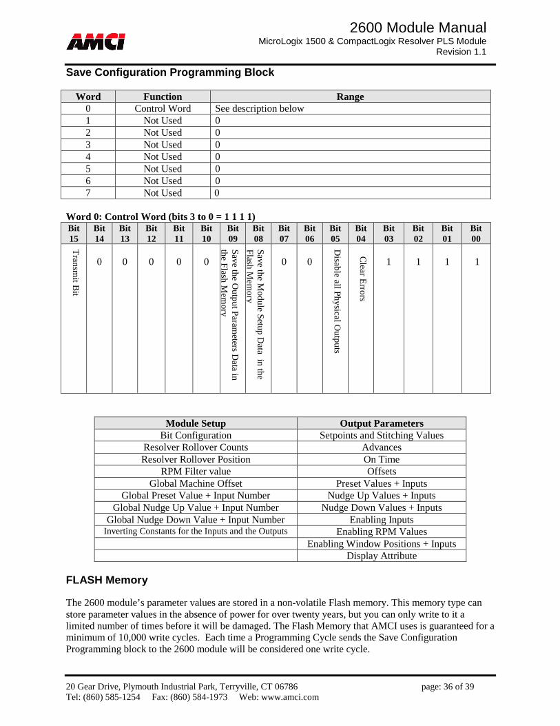
Save Configuration Programming Block
Word Function Range 0 Control Word See description below 1 Not Used 0 2 Not Used 0 3 Not Used 0 4 Not Used 0 5 Not Used 0 6 Not Used 0 7 Not Used 0
Word 0: Control Word (bits 3 to 0 = 1 1 1 1) Bit 15
Bit 14
Bit 13
Bit 12
Bit 11
Bit 10
Bit 09
Bit 08
Bit 07
Bit 06
Bit 05
Bit 04
Bit 03
Bit 02
Bit 01
Bit 00
Tran
smit B
it
0
0
0
0
0
Save th
e Ou
tpu
t Param
eters Data in
th
e Flash
Mem
ory
Save th
e Mo
du
le Setup
Data in
the
Flash
Mem
ory
0
0
Disab
le all Ph
ysical Ou
tpu
ts
Clear E
rrors
1
1
1
1
Module Setup Output Parameters Bit Configuration Setpoints and Stitching Values
Resolver Rollover Counts Advances Resolver Rollover Position On Time
RPM Filter value Offsets Global Machine Offset Preset Values + Inputs
Global Preset Value + Input Number Nudge Up Values + Inputs Global Nudge Up Value + Input Number Nudge Down Values + Inputs
Global Nudge Down Value + Input Number Enabling Inputs Inverting Constants for the Inputs and the Outputs Enabling RPM Values
Enabling Window Positions + Inputs Display Attribute
FLASH Memory The 2600 module’s parameter values are stored in a non-volatile Flash memory. This memory type can store parameter values in the absence of power for over twenty years, but you can only write to it a limited number of times before it will be damaged. The Flash Memory that AMCI uses is guaranteed for a minimum of 10,000 write cycles. Each time a Programming Cycle sends the Save Configuration Programming block to the 2600 module will be considered one write cycle.

20 Gear Drive, Plymouth Industrial Park, Terryville, CT 06786 page: 37 of 39 Tel: (860) 585-1254 Fax: (860) 584-1973 Web: www.amci.com
2600 Module Manual MicroLogix 1500 & CompactLogix Resolver PLS Module
Revision 1.1
Chapter 5: Input Registers (Eight 16 bits words sent from the 2600 module to the PLC)
Word Function Range 0 Status Word See description below
1 Scaled Position 0 to Resolver Rollover Position (This value will not be updated when there is a Clearable Transducer Fault)
2
Velocity in Revolutions per
Minute (RPM)
A positive value indicates that the counts are increasing, and a negative value indicates that the counts are decreasing. One rotation is considered the time it takes the resolver to pass through the programmed rollover counts. For example, if the shaft speed is 100 rpm, and the rollover resolver counts is 2048, then the reported velocity will be 200.
3 Virtual (Backplane)
Output State Bit 0 = Output 0, Bit 1 = Output 1 … Bit 15 = Output 15
4 Physical Output
State at the Terminal Block
Bit 0 = Output 16, Bit 1 = Output 17 … Bit 15 = Output 31
5 Physical Input State
at the Terminal Block
Bit 0 = Input 16, Bit 1 = Input 17 … Bit 15 = Input 31
6 Displayed Attribute Data
See Attribute Table Below 7
Word 0: Status Word Bit 15
Bit 14
Bit 13
Bit 12
Bit 11
Bit 10
Bit 09
Bit 08
Bit 07
Bit 06
Bit 05
Bit 04
Bit 03
Bit 02
Bit 01
Bit 00
AC
Kn
ow
ledg
e Bit
Programming Error Codes
(See Programming Error Code Table
Below)
RP
M clam
ped
wh
en an
Advance V
alue
Exceed
s the R
ollo
ver Co
unt V
alue
Flash
mem
ory h
as been
corrupted
Tran
sdu
cer Fau
lt
Set w
hen
the O
utp
uts are O
verridd
en
Displayed Attribute Data (See Displayed Attribute Table Below)
Bit 7: Set when the Outputs are Overridden. This bit will be set when the PLC is in Program Mode, when
the outputs have been Forced either On or Off, or when the Physical Outputs have been disabled. Bit 8: Set when there is a Transducer Fault. This bit will be set if a Transducer Fault has been detected.
Possible causes are a miss wired cable, an incompatible resolver transducer, a faulty transducer, or a faulty 2600 module. A document showing How Do I Test an AMCI Resolver System to determine which of the previous is the cause of the Transducer Fault is available from the FAQ section of our website.

20 Gear Drive, Plymouth Industrial Park, Terryville, CT 06786 page: 38 of 39 Tel: (860) 585-1254 Fax: (860) 584-1973 Web: www.amci.com
2600 Module Manual MicroLogix 1500 & CompactLogix Resolver PLS Module
Revision 1.1
Bit 9: Set when the Flash Memory has been corrupted. The 2600 module saves its setup parameters through power down in a Flash Memory. This bit will be set to indicate that data stored in this device is in some way not valid. To clear this error, program the module with new parameters, or restore the factory default parameters, and then save these new parameters in the flash memory. If this does not work, the flash memory may be damaged and the unit may have to be returned to be repaired.
Bit 10: RPM clamped when an Advance Value Exceeds the Rollover Count Value The 2600 module calculates how much an output needs to be advanced, in counts, based on the programmed advanced values and the rotating speed of the resolver. Unpredictable operations will occur if this number of counts exceeds the programmed Rollover Count Value. The 2600 module sets this bit to indicate to the PLC that the advanced output may not be firing correctly.
Bits 11 to 14: Programming Error Bits
Programming Error Codes Bit 14
Bit 13
Bit 12
Bit 11 Description
0 0 0 0 No Errors
1 0 0 0
Command Word Error • Set if the unused bits are set in the Command Word • Selecting both Simple and Pulse ANDing at the same time • Will be cleared with next correct Command Word
1 0 0 1
Programmed Parameter is outside defined boundary • Entering a value other than zero in the unused words (output words 1 to 7)
that exist in some of the programming blocks • Requires Clear Error command bit
1 0 1 0 Parameter bits are set in reserved bit fields that must be 0
• Requires Clear Error command bit
1 0 1 1
Programmed parameter is in conflict with another programmed parameter • For example, Rollover Position = 359 and a Limit Switch ON Setpoint =
360 • Setting the Count Direction and Slave Mode bits at the same time • Selecting both Distance and RPM Advances and Millisecond Advances at
the same time • Requires Clear Error command bit
1 1 0 0 Programmed setpoint overlays another setpoint of the same output
• For Example, setpoint 0 = 10 to 20 degrees, setpoint 1 = 15 to 25 • Requires Clear Error command bit
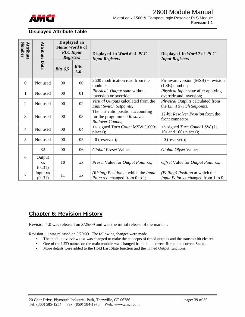
20 Gear Drive, Plymouth Industrial Park, Terryville, CT 06786 page: 39 of 39 Tel: (860) 585-1254 Fax: (860) 584-1973 Web: www.amci.com
2600 Module Manual MicroLogix 1500 & CompactLogix Resolver PLS Module
Revision 1.1
Displayed Attribute Table
Attribute
Num
ber
Attribute D
ata
Displayed in Status Word 0 of
PLC Input Registers
Displayed in Word 6 of PLC Input Registers
Displayed in Word 7 of PLC Input Registers
Bits 6,5 Bits 4..0
0 Not used 00 00 2600 modification read from the module;
Firmware version (MSB) + revision (LSB) number;
1 Not used 00 01 Physical Output state without inversion or override;
Physical Input state after applying override and inversion;
2 Not used 00 02 Virtual Outputs calculated from the Limit Switch Setpoints;
Physical Outputs calculated from the Limit Switch Setpoints;
3 Not used 00 03 The last valid position accounting for the programmed Resolver Rollover Counts;
12-bit Resolver Position from the front connector;
4 Not used 00 04 +/- signed Turn Count MSW (1000s places);
+/- signed Turn Count LSW (1s, 10s and 100s places);
5 Not used 00 05 =0 (reserved); =0 (reserved);
6
32 00 06 Global Preset Value; Global Offset Value;
Output xx
(0..31) 10 xx Preset Value for Output Point xx; Offset Value for Output Point xx;
7 Input xx (0..31)
11 xx (Rising) Position at which the Input Point xx changed from 0 to 1;
(Falling) Position at which the Input Point xx changed from 1 to 0;
Chapter 6: Revision History Revision 1.0 was released on 3/25/09 and was the initial release of the manual. Revision 1.1 was released on 5/20/09. The following changes were made.
• The module overview text was changed to make the concepts of timed outputs and the transmit bit clearer. • One of the LED names on the main module was changed from the incorrect Run to the correct Status. • More details were added to the Hold Last State function and the Timed Output functions.