modules, ports, instantiation - oregon state...
TRANSCRIPT

Modules, ports, instantiationI Development of timing and state diagrams refined the block diagramI Cleaned up and added better names, added detail
FILE: REVISION:
DRAWN BY: PAGE OF
TITLE
multiplicand_reg
prod_reg_high
32
32
mult3_ctl
multiplier_bit_0
a_in b_in
32
shift
load
64
32
start
32
32 32
32
done
shift
load
prod_reg_shift_rt
reg_a
’0
0 1S start
start
startB
LS
product
prod_reg_ld_high
prod_reg_low
D
Q
D
Q
D
Q

Modules, ports, instantiationI As its reasonable, we want to maintain our partitioning in SVI We have two mechanisms to do this: modules and always blocks
FILE: REVISION:
DRAWN BY: PAGE OF
TITLE
multiplicand_reg
prod_reg_high
32
32
mult3_ctl
multiplier_bit_0
a_in b_in
32
shift
load
64
32
start
32
32 32
32
done
shift
load
prod_reg_shift_rt
reg_a
’0
0 1S start
start
startB
LS
product
prod_reg_ld_high
prod_reg_low
D
Q
D
Q
D
Q

Modules, ports, instantiationI Simple functionality belongs in an always block.I If considerable complexity or natural boundary (data vs. control)
exists, a module is appropriate.I Our datapath logic is simple and will be in always blocksI ”mult3 ctl” is a natural partitioning boundary and will be in its own
module.
FILE: REVISION:
DRAWN BY: PAGE OF
TITLE
multiplicand_reg
prod_reg_high
32
32
mult3_ctl
multiplier_bit_0
a_in b_in
32
shift
load
64
32
start
32
32 32
32
done
shift
load
prod_reg_shift_rt
reg_a
’0
0 1S start
start
startB
LS
product
prod_reg_ld_high
prod_reg_low
D
Q
D
Q
D
Q

Modules, ports, instantiation
The module is the basic unit of hierarchy in VerilogI Modules describe:
I boundaries [module, endmodule]I inputs and outputs [ports]I how it works [behavioral or RTL code]
I Can be a single element or collection of lower level modules
I Module can describe a hierarchical design (a module of modules)
I A module should be contained within one file
I Module name should match the file name
I Module mult3 ctl resides in file named mult3 ctl.sv
I Multiple modules can reside within one file (not recommended)
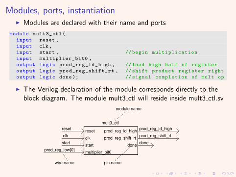
Modules, ports, instantiationI Modules are declared with their name and ports
module mult3_ctl(
input reset ,
input clk ,
input start , //begin multiplication
input multiplier_bit0 ,
output logic prod_reg_ld_high , //load high half of register
output logic prod_reg_shift_rt , //shift product register right
output logic done); // signal completion of mult op
I The Verilog declaration of the module corresponds directly to theblock diagram. The module mult3 ctl will reside inside mult3 ctl.sv
FILE: REVISION:
DRAWN BY: PAGE OF
TITLE
multiplicand_reg
prod_reg_high
32
32
mult3_ctl
multiplier_bit_0
a_in b_in
32
shift
load
64
32
start
32
32 32
32
done
shift
load
prod_reg_shift_rt
reg_a
’0
0 1S start
start
startB
LS
product
prod_reg_ld_high
prod_reg_low
D
Q
D
Q
D
Q
mult3_ctl
reset
clk
start
multiplier_bit0
prod_reg_ld_high
prod_reg_shift_rt
done
pin name
prod_reg_low[0]
wire name
module name
reset
clk
start done
prod_reg_ld_high
prod_reg_shift_rt

Modules, ports, instantiation
I CommentsI Comments are done just like CI One line comments begin with //I Multi-line comments start with /*, end with: */
I IdentifiersI Identifiers are names given to objects so that they may be referencedI They start with alphabetic chars or underscoreI They cannot start with a number or dollar signI All identifiers are case sensitive unlike VHDL

Modules, ports, instantiation
I ANSI C Style Ports in System Verilog are declared as:I port mode, port type, port width, port name... where:
I Port mode is input, output or inoutI Port type defaults to wire, outputs are usually type logicI Port width is [MSB:LSB]I Port name is simply the name of the port
input [31:0] register_in , // register input
output logic [31:0] register_out , // register output
I Input ports are understood as nets (wires) within the module, andcan only be read from.
I Output ports are understood as nets (wires) withing the module andcan be read from or written to if they are type logic.
I Inout ports are understood as nets (wires) withing the module andcan be read from or written to if they are type logic.
I Use inout ports for tri-state logic only.

Modules, ports, instantiation
Hierarchical Design
I Hierarchical designs have a top level module and lower level modules.
I Lower level modules (like mult3 ctl) are instantiated within thehigher level module (mult3)
FILE: REVISION:
DRAWN BY: PAGE OF
TITLE
mult3
reset
clk
start
product
done
64
a_in
b_in32
32
mult3_ctl
reset
clk
start
multiplier_bit0
prod_reg_ld_high
prod_reg_shift_rt
done
’00 1
S
multiplicand_reg
D
Q
product_reg
D
Q

Modules, ports, instantiation
I Module mult3 is just a higher-level module, so we define it as before.
I Module mult3 will reside in another file called mult3.sv.
I The beginning of mult3.sv looks like this:
module mult3(
input reset ,
input clk ,
input [31:0] a_in ,
input [31:0] b_in ,
input start ,
output logic [63:0] product ,
output logic done);

Modules, ports, instantiationI Module mult3 ctl is instantiated within mult3 as shown and is
concluded with the keyword endmodule
module mult3(
input reset ,
input clk ,
input [31:0] a_in ,
input [31:0] b_in ,
input start ,
output logic [63:0] product ,
output logic done);
//
// Other code goes in here
//
// instantiate the control module
mult3_ctl mult3_ctl_0(
.reset (reset ),
.clk (clk ),
.start (start ),
.multiplier_bit0 (prod_reg_low [0] ),
.prod_reg_ld_high (prod_reg_ld_high ),
.prod_reg_shift_rt (prod_reg_shift_rt ),
.done (done ));
endmodule

Modules, ports, instantiation
I The instantiation associates a wire in an upper-level module with apin (or port) on a lower level module. Pins on left, wires on right.
FILE: REVISION:
DRAWN BY: PAGE OF
TITLE
multiplicand_reg
prod_reg_high
32
32
mult3_ctl
multiplier_bit_0
a_in b_in
32
shift
load
64
32
start
32
32 32
32
done
shift
load
prod_reg_shift_rt
reg_a
’0
0 1S start
start
startB
LS
product
prod_reg_ld_high
prod_reg_low
D
Q
D
Q
D
Q
mult3_ctl
reset
clk
start
multiplier_bit0
prod_reg_ld_high
prod_reg_shift_rt
done
pin name
prod_reg_low[0]
wire name
module name
reset
clk
start done
prod_reg_ld_high
prod_reg_shift_rt
// instantiate the control module
mult3_ctl mult3_ctl_0(
.reset (reset ),
.clk (clk ),
.start (start ),
.multiplier_bit0 (prod_reg_low [0] ), //LSB of product reg
.prod_reg_ld_high (prod_reg_ld_high ),
.prod_reg_shift_rt (prod_reg_shift_rt ),
.done (done ));

Modules, ports, instantiation
Instantiation subtleties
I Ports of the upper-level module are understood to be wires withinthat module.
I Wires connected to pins can have differing names.
I Wires and pins should not have differing widths!
I Followng the module name is an instance name that makes eachinstantiation of the same module unique.
mult3_ctl mult3_ctl_0(
I Comment each line if designer intention is not crystal clear.
I This method of instantiation is called named association. Its thepreferred way of doing instantiation when pins/names differ.

Modules, ports, instantiation
I Its possible to instantiate using pin/wire position only.
I This is called positional association. Its a bad idea.
I For example:
// instantiate the control module
mult3_ctl mult3_ctl_0(reset ,clk ,start ,prod_reg_low [0],
prod_reg_ld_high , prod_reg_shift_rt ,done);
I How do you know pins and wires are connected correctly?
I Could you check it quickly if the module had 50 pins on it?
I What if you wanted to add wire in the middle of the list?
I Do not use Positional Association!
I It saves time once, and costs you dearly afterwords

Modules, ports, instantiation
Implicit Naming is useful when most pins/wires have the same name.
// instantiate the control module
mult3_ctl mult3_ctl_0(
.reset (reset ),
.clk (clk ),
.start (start ),
.multiplier_bit0 (prod_reg_low [0] ), // product reg LSB
.prod_reg_ld_high (prod_reg_ld_high ),
.prod_reg_shift_rt (prod_reg_shift_rt ),
.done (done ));
// instantiate the control module
mult3_ctl mult3_ctl_0(
.reset ,
.clk ,
.start ,
.multiplier_bit0 (prod_reg_low [0]), //named association
.prod_reg_ld_high ,
.prod_reg_shift_rt ,
.done );
Implicit and named association forms can be mixed

Modules, ports, instantiation
If all pins and associated wires have the same name we can do this:
// instantiate the control module
mult3_ctl mult3_ctl_0 (.*); //now that ’s a short cut!
I This is the most powerful form of implicit association.
I This method is best reserved for top level testbench/top moduleinstantiation, else, it could hide intent.

Modules, ports, instantiation
Unconnected port pins may be left unconnected like this...
// instantiate the control module , don ’t need connection to done pin
mult3_ctl mult3_ctl_0(
.reset (reset ),
.clk (clk ),
.start (start ),
.multiplier_bit0 (prod_reg_low [0] ), // product reg LSB
.prod_reg_ld_high (prod_reg_ld_high ),
.prod_reg_shift_rt (prod_reg_shift_rt ),
.done ( ));
I Unused ports may simply be left out of the port list...bad idea!
I Keep your intent clear!
I Careful formatting of names, parenthesis and commas makes it easyto catch errors.

Modules, ports, instantiationI How are lower level modules connected if a port definition has not
created the wire?I In the upper-level module, wires are declared; usually near the
beginning of the module.
module mult3(
input reset ,
input clk ,
input [31:0] a_in ,
input [31:0] b_in ,
input start ,
output logic [63:0] product ,
output logic done);
// declare internal wires
logic [31:0] reg_a; //output , multiplicand reg
logic [31:0] prod_reg_high; //output , upper half of product reg
logic [31:0] prod_reg_low; //output , lower half of product reg
logic prod_reg_ld_high; //load , upper half of product reg
logic prod_reg_shift_rt; //shift product regright
//lots more code goes here
endmodule

Modules, ports, instantiation
I Format of wire declaration is: type width[MSB:LSB] wire name;
I Width is optional
logic [31:0] prod_reg_low; // lower half of product register
I If no width is given, the wire is assumed to be a single conductor.
I If width is given, a bus is created of that width. Busses are groupsof logically related wires.

Modules, ports, instantiation
I Parametrization of modules allows for code reuse
I In the module declaration, the keyword ”parameter” is optional
//a generic width register declaration
module multi_reg #( parameter width =8) (
input reset
input clk
input enable
input data_in [width -1:0]
output logic data_out [width -1:0]
)
\\
\\ description of register goes here
\\
endmodule

Modules, ports, instantiation
I The parametrized register could be instantiated like this:
module top_module;
logic [31:0] data_out;
wire reset , clk , enable , data_in;
// instantiate register and override width to 32 bits
multi_reg #(. width (32)) multi_reg_0(
.reset (reset ),
.clk (clk ),
.enable (enable ),
.data_in (data_in ),
.data_out (data_out ));
endmodule

Modules, ports, instantiation
I Verilog modules...I provide a coarse-grain structuring mechanismI contain RTL logic or other modulesI provide an abstraction mechanism via complexity hidingI provide a way for design reuse
I Question: How is a Verilog module different from a C function?