rdl: a language for framework instantiation representation · rdl: a language for framework...
TRANSCRIPT

1
RDL: A Language for Framework
Instantiation Representation
Toacy C. Oliveira, Paulo S. C. Alencar, Carlos J.P. de Lucena, Donald D. Cowan.♦
Abstract — Reusing software artifacts for system development is showing increasing
promise as an approach to reducing the time and effort involved in building new systems,
and to improving the software development process and the quality of its outcome.
However, software reuse has an associated steep learning curve, since practitioners must
become familiar with a third party rationale for representing and implementing reusable
assets. For this reason, enabling a systematic approach to the reuse process by making
software reuse tasks explicit, allowing software frameworks to be instantiated using pre-
defined primitive and complex reuse operations, and supporting the reuse process in a
(semi-)automated way become crucial goals. In this paper, we introduce a systematic
reuse approach and Reuse Description Language (RDL), a language designed to specify
object-oriented framework instantiation processes, and an RDL execution environment,
which is the tool support for definition and execution of reuse processes and framework ♦ Toacy C. Oliveira is with Faculty of Informatics at the Pontifical University Catholic of Rio Grande do
Sul, Brazil . His e-mail address is [email protected]. Paulo S. C. Alencar and Donald D. Cowan are with
the School of Computer Science at the University of Waterloo, Ontario, Canada. Their e-mail addresses are
{palencar, dcowan} @csg.uwaterloo.ca respectively. Carlos J. P. de Lucena is with the Computer Science
Department at the Pontifical University of Rio de Janeiro Brazil. His e-mail is [email protected].

2
instantiations that lead to domain-specific applications. We illustrate our approach using
JUnit, a framework for testing.
1 Introduction
Reusing software artifacts for system development has increasingly become a promising
approach with the potential of reducing the time and effort involved in building new
systems, and improving the software development process and the quality of its outcome.
However, software reuse has an associated steep learning curve since practitioners must
become familiar with a third party rationale for representing and implementing reusable
assets [1]. As a result, the effort to reuse can be compared to the effort of developing a
new artifact where a systematic approach is not adopted [2]. For this reason, the reuse
process can be facilitated by representing reuse activities by means of process
specifications that make explicit the software reuse tasks and thus liberating re-users from
mining rationale directly from the reusable software asset design or code. Moreover, the
process specifications can be mechanically processed enabling the construction of reuse
wizards to automate or semi-automate the reuse process.
To mitigate the issues just raised, we have developed RDL, which stands for Reuse
Description Language, a language that can be used procedurally for the process
specification of object-oriented framework instantiation. When using RDL, framework
developers can specify the sequence in which reuse actions must be executed as well as
the constraints involved in the instantiation of reusable assets, such as frameworks.
Moreover, RDL allows the specification of asynchronous reuse activities of the type
widely used in Global Software Development [3]. As a result, the framework re-user is

3
guided through a set of reuse actions and can focus on the relevant parts of the framework
that should be adapted during the instantiation process.
In this paper, we thoroughly present the RDL language, depicting the elements RDL can
manipulate, the syntax and semantics for the most important commands and the impact
on design during the script execution. We also present RDL execution model, its
associated software architecture and illustrate the approach applicability using the JUnit
framework. In addition we briefly present the xFIT (XML-based Framework Instantiation
Tool) approach, which is the reuse approach where the RDL execution environment is
embedded in. It’s worthwhile mentioning that RDL is part of a more comprehensive
reuse approach used for Product Engineering [4] (see, for example, [5] [6] [7] [8]).
This paper is organized as follows. In Section 2 we describe related work on software
reuse and explain how existing methods relate to the RDL approach. In Section 3 we
provide background and motivation for this work. Section 4 introduces xFIT, a software
reuse approach in which RDL in embedded. In Section 5 we briefly describe UML-FI, a
representation for object-oriented frameworks and its flexible points, also called hotspots
or points of variability. Section 6 describes RDL, the process language used to represent
framework changes and instantiation processes, and provides its rationale and process-
oriented commands. In Section 7 we describe the underlying execution infrastructure for
RDL, and in Section 8 we illustrate the applicability of RDL using JUnit, an object-
oriented framework for testing. Finally, in Section 9 we present our conclusions and
discuss some future directions.

4
2 Related Work
In this section, we describe existing work on software reuse related to framework
instantiation, product lines and model-driven architectures.
In [9] the authors have proposed a structured specification to support framework
instantiation. They have introduced a template called Cookbook applied to a reuse
document expressed in natural language, which can be difficult to follow because of the
lack of a formal underlying approach. Moreover, Cookbooks can not be processed
automatically, possibly leading to inconsistencies in their definition. As an extension to
Cookbooks, Hooks [10] also provided a template for framework instantiation assistance
and, as a result, share similar problems.
In the area of framework instantiation guidance, Active Cookbooks[11] advocate the use
of Software Agents to execute instantiation plans. The main issue with the HiFi[11]
approach is that it introduces non-standard notations such as TOON [11] into the
application development process that can cause an extra burden to framework
development. In OBS [12] the authors used a generative approach to framework
instantiation that shares some of the features of our previous work [13]. However, the
OBS approach is based on ready-to-use blackbox frameworks, which restricts
instantiation processes to component configuration, and does not focus on customization.

5
Product Line Architectures also lead to approaches to support generating applications
from pre-defined software components that can be configured based on a decision
model[45]. In Gomaa [14] the author has presented a technique to develop Software
Product Lines using UML diagrams and Feature Models. However, the lack of tool
support causes difficulties for systematic adoption. Another initiative using the Features
model is the Generative Programming (GP) approach described in [15], where the author
proposes the development of Domain Specific Languages (DSLs that can be visual or
textual) as a means to generate programs from high-level specifications and
transformations. Although we share some underlying principles with the GP approach,
we believe that well-known and standard notations and paradigms such as UML and
object-oriented programming need to be used in the definition of process-related
specifications and transformations. For this reason we use an extension of UML to
represent frameworks and define RDL as a language to transform the extended UML
models. In the same research direction, the WebML approach [16] guides developers
through a set of pre-defined windows that can be seen as DSLs to collect application-
specific information to create Web Applications. In the WebML approach the
configuration knowledge is hard-coded into the tool, which complicates its extension to
incorporate the evolution of specific domain requirements.
OMG’s Model Driven Architecture [17] (MDA) is also an attempt to systematize reuse
using UML, OCL [18] and software transformations [17]. The MDA approach can use
modeling languages such as UML to represent software in a platform-independent
manner. As a result, specific platform code can be automatically generated using a set of

6
pre-defined transformations. However, MDA is still in the Request for Proposal (RFP)
[19] phase wherein researchers are collaborating to develop a set of specifications,
including notations for the transformation process.
3 Background and Motivation
We have developed object-oriented frameworks for several domains. Some of these
frameworks were produced as result of academic research activities [20] [21] [22] [23],
while others were developed in the context of partnerships between industry and
academia [24][25][26][27]. Typically their development relied on gathering knowledge
about a domain (Domain Analysis) and applying object-oriented programming expertise
to implement flexible software [28]. However, the reuse processes were cumbersome
since they were usually handled by programmers who had little experience in the design
rationale for the frameworks. For instance, in the DSSFrame framework [26], where the
extension points were constrained in a proper instantiation sequence, the framework
designers had to spend a substantial amount of time to explain the design and supervise
the team of “instantiators1”.
In addition, as was the case with DSSFrame, reuse can be handled in an environment that
is distributed, with developers in more than one site; or asynchronous where developers
are not in constant collaboration because of different schedules. As a result, the sequence
1 Those in charge of instantiation activities, who are also called re-users in this work.

7
in which instantiation activities are executed is a major issue and must be supported by
tools [29][3].
Under these circumstances, we began to develop approaches to assist instantiation
processes [30]. However, the need for tools was very clear and, therefore, we
concentrated on the specification and development of techniques for this purpose. The
baseline specification we assumed for these tools had three key constraints:
⇒ Use standards found in the Software Engineering discipline such as UML, XMI [31]
and typical object-oriented programming activities, to reduce the approach’s learning
curve.
⇒ Represent the process in a way that can be automated by an execution environment.
⇒ Assist the re-user as much as possible.
As a result, we developed xFIT, the XML-based Framework Instantiation Tool, which
embodies our reuse approach in a tool. xFIT guides re-users through the framework
instantiation process by exposing the frameworks’ high-level characteristics through a
Feature Model [32]. Such features are then traced to design elements specified in UML-
FI, a UML profile responsible for exposing framework extension points at the design
level. In order to automate the process, RDL expresses how each extension point should
be extended to create the final application. In this approach XML is a key technology,
since most of documents are expressed in XML.
4 Introducing the xFIT Approach
The xFIT approach is intended to facilitate the framework instantiation processes by
means of a tool that executes instantiation scripts written in RDL. Ideally xFIT takes as

8
input three types of documents as shown in Figure 1: a Features Model, an Annotated
Framework Design, and a RDL Instantiation Script.
Figure 1 – An overview of our approach from [5].
The Features Model is used as the original formulation [32] and is intended to provide a
high-level visualization for the framework’s characteristics. The annotated framework
design is the representation of an object-oriented framework using UML. Actually, in
order to represent all flexible characteristics embedded in the framework design, we have
developed and adopted UML-FI (UML for Framework Instantiation), which is an
extended version of UML designed to emphasize the flexible elements in a OO design.
UML-FI will be briefly introduced in Section 5.
The last document is the Instantiation Script, which specifies the instantiation process so
that a framework re-user can be guided in accommodating the application specific needs

9
into the framework’s extension points. In order to achieve a succinct process description
we have developed RDL (Reuse Description Language), a language that allows the
specification of order and state dependencies among object-oriented programming
activities that are often used when instantiating an incomplete design.
To integrate the three technologies, Features, a Framework’s Annotated Design and the
Instantiation Script, we created a mapping technique using UML trace mechanisms that
relates the flexibility represented by optional and alternative features found in the
Features Model, to extension points (hotspots) in the framework design [7]. By doing so,
the xFIT execution environment can partially generate the RDL script that is used to
tailor the framework design. We achieved this goal by creating RDL instantiation
templates that are associated with each UML-FI stereotype (see Section 5) and executed
when a corresponding feature was chosen.
We also have the ability to run RDL scripts that are manually created by the Framework
Designer and are not related to a Features Model. We believe that for frameworks with
several extension points, where each feature is not easily related to a single design
element such as a class, the mapping approach may not be feasible.
Our approach consists of two different phases: the Framework Engineering Phase and the
Framework Instantiation Phase. During the Framework Engineering Phase, the
framework designer (or engineer) needs to develop the framework and provide the
mechanisms to facilitate its reuse (Figure 2). In other words the framework design must

10
be annotated using UML-FI stereotypes and tagged values and a Features Model must be
created to represent the framework’s characteristics at a high-level of abstraction. This
Features Model will also expose aspects of the framework’s flexibility and, finally, relate
features and UML-FI design elements. It is possible to skip the last phase and to create
the RDL scripts manually.
Figure 2 – Framework engineering process.
The Framework Instantiation Time is when a framework’s extension points are
completed with application-specific increments [28]. In this context, the framework
instantiation process, which shows how to produce the software product (the application),
begins with the stakeholder2 selecting the features to be included in the specific software
2 Stakeholder in our scenario is someone interested in the framework reuse.

11
product. The selected characteristics (shown in dark gray in the Features Model of Figure
1), together with the annotated class model, will be provided as input into the xFIT tool
that will generate an instantiation script containing the necessary steps to instantiate an
application with the desired characteristics.
The proposed instantiation process finishes when the instantiation script is executed using
an RDL execution environment such as xFIT (Figure 3c). The RDL execution
environment will then modify the original design of a framework by inserting/removing
some design elements to adapt the hotspots to meet the requirements of a specific
application. It is worth mentioning that this last step is not entirely automatic in that the
application developers need to provide additional information such as class names,
attribute names and types, and method names.
Figure 3 illustrates the RDL execution scenario. Figure 3a represents a fragment of a
framework design in UML containing a class Figure, which is an extension point, and the
associated RDL script. The Instantiation occurs when the application increments
represented by the classes Circle and Square (Figure 3b) are combined with the
framework design.

12
Figure 3 RDL Execution approach
Although the best way to follow an RDL script is using an execution environment such as
xFIT, we believe that RDL commands can be processed by humans. We base this
assumption on the fact that RDL syntax and semantics are based on ordinary
programming activities thus facilitating understanding.
We close this overview with an important additional remark: the documents used in our
approach are XML-based. We have adopted the XML technology, since it has broad
support from standards bodies such as W3C and it is commonly accepted or adopted by
the academic community and industry. Moreover, based on our past experience [33][13],
XML models are suitable for program manipulation and can be translated to formal
models that can be validated.

13
5 UML-FI
In this section we present the main UML-FI (UML for Framework Instantiation) notation
constructs, an extension we have developed to specify object-oriented frameworks and
the instantiation of their extension points. UML-FI is a UML profile containing
stereotypes and tagged-values (i.e., UML extension mechanisms) to indicate, at the
design level, the object-oriented activities that should be performed when instantiating a
framework.
Notation Base Class Description <<CLASS_EXTENSION>> class Indicates that the current class requires subclassing. <<PATTERN_CLASS_ EXTENSION>>
class Indicates that the current class requires subclassing, which is achieved through the application of a pattern.
<<SELECT_CLASS_ EXTENSION>> class Indicates that the current class requires subclassing, which is achieved by selecting one of its known subclasses.
<<METHOD_EXTENSION>> method Indicates that the current method requires redefinition in a subclass.
<<PATTERN_METHOD_ EXTENSION>> method Indicates that the current method requires redefinition in a subclass, which is achieved with the application of a pattern.
<<VALUE_ASSIGNMENT_ EXTENSION>> attribute Indicates that the current attribute requires a value. <<VALUE_SELECTION_ EXTENSION>> attribute Indicates that the current attribute requires a value, which can
selected from a list of given values.
Table 1 – UML-FI Stereotypes.
Tag Name Stereotype Description Presence Class, Attribute, Method Qualifies the design element as mandatory in the final design. The default
is “presence = mandatory”. {mandatory, optional}
Table 2 – UML-FI Tagged values.
It is possible to indicate in UML-FI most basic object-oriented programming activities
such as class extension, method redefinition and value assignment (useful for Blackbox
framework instantiation [1]). These activities are defined by means of annotations
(stereotypes and tagged values shown in Tables 1 and 2) in class diagrams (Figure 4).

14
Figure 4 – Class extension stereotype.
. In addition, extension points can also be mandatory or optional. Therefore, the re-user
can decide if the associated design element will (or will not) be present in the final
application. UML-FI indicates optional and mandatory aspects as a tagged-value named
presence that can assume the values OPTIONAL or MANDATORY (Figure 5).
Figure 5 – Optional representation.
6 RDL
Instantiation processes tailor a framework’s design and code based on carefully
developed elements called Extension Points3 (EP). In order to adapt a framework’s EP, a
re-user must execute a set of Instantiation Tasks (IT) that are closely related to ordinary
activities performed when programming. For instance, a whitebox framework’s ITs can
be related to specializing classes and/or redefining methods; on the other hand, a
blackbox framework’s ITs are focused on parameterization. Thus a language built to
3 In this work the terms Extension Points and Hotspots are equivalent.

15
specify a process to control the execution of ITs must use the same rationale adopted
when programming the framework.
In order to systematize instantiation processes RDL allows the definition of an
instantiation script document, containing the ITs required to derive the application from
the framework’s design and code. Moreover, ITs must be executed in a proper sequence,
which can also be specified within a RDL script.
The structure of an RDL instantiation script is the same as found in most imperative
programming languages, namely program constructs and procedures. However, in order
to follow the usual framework instantiation terminology, we use the term Cookbook [9]
to represent a program and Recipe [9] to represent a procedure. Every Cookbook must
have a Recipe called main that identifies the instantiation process execution entry point as
shown in Code 1.
COOBOOK Example RECIPE main // do something END_RECIPE; END_COOKBOOK
Code 1 – A Cookbook example.
Note that the instantiation process is totally dependent on the final application domain
that constrains the extension points to a proper set of values. For instance, in an
eCommerce framework, the elements can be books, CDs or cars and are not known
during the framework engineering but only during instantiation. As a result, the RDL
instantiation script does not have all the information needed to transform the framework
design automatically into the application design. Instead, it must interrogate the re-user

16
for the missing information. That is why we refer to our instantiation approach as being
systematic, not automatic.
6.1 Manipulated Elements
The instantiation process must produce an application from an incomplete model, since
extension points represent flexible characteristics in the model that can not be specified
during framework design. For instance, a designer developing a framework for the
eCommerce domain must not fix the element under trade, thus providing more reuse
opportunities.4 Therefore, during instantiation of the eCommerce framework, new design
elements to specify the product under trade must be added to bring the model to a
complete and coherent state.
In our case, a model is a slight adaptation of UML Class Diagrams (see UML-FI in
Section 5) and what RDL does is provide syntax and semantics to a process that
manipulates meta-elements such as the ones present in the UML meta-model Abstract
Syntax [34]. We did not use high level elements found in the meta-model hierarchy such
as ModelElement, Feature or Classifier, instead we used specialized elements such as
Class, Method, Attribute and Relationship, in order to reduce the number of elements
RDL needs to manipulate and improve clarity. Moreover, using those specialized
elements led to a straightforward connection with ordinary object-oriented programming
principles.
4 According to Parnas [35], the amount of reuse opportunities increases when you do not
restrict the representation of an application family to a specific domain.

17
It is important to mention that the meta-class ReusableElement was introduced in the
UML meta-model as a super class for Class, Method and Attribute, and is manipulated by
RDL scripts. In fact, some operation and attributes are common to all design elements,
and using inheritance to capture the common features is an obvious choice.
Although UML focuses on design, code is also an important element in the reuse process.
For that reason we decided to incorporate the representation of Programming Language
idioms using the UML element named ProcedureExpression [34]. When an RDL script
uses a ProcedureExpression, it becomes tied to that language and can not be used in
instantiation processes with different languages. However, a framework is usually the
incomplete version of a running application, being actually represented in a programming
language that has already been chosen.
Another UML element that is manipulated with RDL is a Note. Notes allow framework
designers to add extra documentation and instantiation hints. For example, assigning
values to the parameters found in Blackbox Frameworks can be done anywhere in the
code so there is no way to determine where such assignment will take place during the
instantiation process. Sticking a note to a parameter with some documentation stating that
the assignment must occur and listing the elements involved provides a hint about the
parameter instantiation to the framework re-user.

18
6.2 RDL Commands
Commands in RDL must ultimately cover object-oriented programming activities and
ordinary programming statements such as loop, assignment and conditional. Although
our underlying principle to create RDL was the same adopted by Meyer [36], who states
that a language must be concise with few and seamless commands, our goal was also to
raise RDL reuse expressiveness. To achieve this goal, we have incorporated a set of
language elements specifically related to instantiation tasks and have organized RDL
statements into five groups according to their purpose within the instantiation process:
Basic Programming Tasks, Instantiation Specific Tasks, Pattern Specific Tasks, Sequence
Specific Tasks and Miscellaneous Tasks (See Section 6.3).
The following sections 6.3 to 6.8 present RDL from its execution perspective, showing
how design and code are changed after the execution of a command. Each Instantiation
Task is presented in a table using the structure Command, Syntax, Description, Code and
Design, where:
⇒ Command – Specifies the Command name to be used in a informal manner.
⇒ Syntax – Specifies the command sentence structure to be used within the RDL
script. In some cases the notation used is similar to C functions as in as
return_type CommandName (parameter_list), where return_type specifies the
type of the returned element; CommandName is the name of the command; and
parameter_list is a placeholder to receive arguments.
⇒ Description – Provides a textual description to the task intention.
⇒ Comments – Provides extra information when needed (this part is optional).
⇒ Code – Shows an example of use of the command within a RDL script.
⇒ Design – Illustrates how design is modified after the RDL script execution.

19
In order to provide a more general and complete representation, a BNF-like specification
is shown in Appendix I.
6.3 Basic Programming Tasks
Basic Programming Tasks (BPTs) represent ordinary design and code manipulation
activities and are presented in Tables 3 to 7.
Command: Class Creation
Syntax: class new_class ( cName )
Description: Indicates the action of creating a class named cName in the design. Returns the created
class for further manipulation.
Code:
COOBOOK Example RECIPE main // adding a new class NEW_CLASS (Class2); //… END_RECIPE; END_COOKBOOK
Design:
Table 3 – Class Creation Command
Command: Method Creation
Syntax: method new_method (c, metName)
Description: Indicates the action of creating a method named metName in class c. Returns the created
method.
Code:
COOBOOK Example RECIPE main // adding a new method NEW_METHOD (Class1,operation1); // END_RECIPE; END_COOKBOOK
Design:
Table 4 – Method Creation Command
20
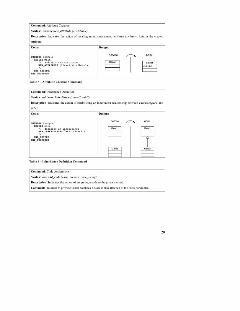
Command: Attribute Creation
Syntax: attribute new_attribute (c, attName)
Description: Indicates the action of creating an attribute named attName in class c. Returns the created
attribute.
Code:
COOBOOK Example RECIPE main // adding a new attribute NEW_ATTRIBUTE (Class1,attribute1); // END_RECIPE; END_COOKBOOK
Design:
Table 5 – Attribute Creation Command
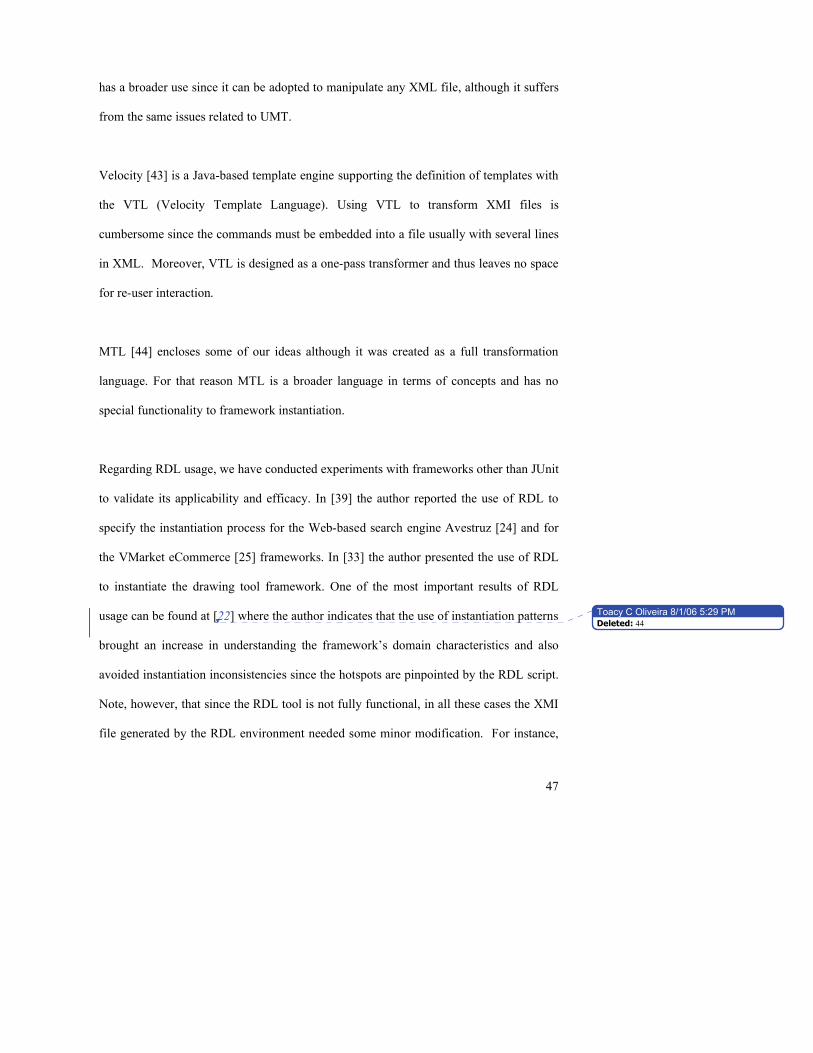
Command: Inheritance Definition
Syntax: void new_inheritance (superC, subC)
Description: Indicates the action of establishing an inheritance relationship between classes superC and
subC.
Code:
COOBOOK Example RECIPE main // defining an inheritance NEW_INHERITANCE(Class1,Class2); // END_RECIPE; END_COOKBOOK
Design:
Table 6 – Inheritance Definition Command
Command: Code Assignment
Syntax: void add_code (class, method, code_string)
Description: Indicates the action of assigning a code to the given method.
Comments: In order to provide visual feedback a Note is also attached to the class parameter.

21
Code:
COOBOOK Example RECIPE main // assigning code ADD_CODE(Class1,operation1,”{ // this is the code to be added }”); // END_RECIPE; END_COOKBOOK
Design:
Table 7 – Code Assignment Command
6.4 Instantiation Specific Tasks
Instantiation Specific Tasks (ISTs) raise the abstraction level found in RDL scripts since
they provide a vocabulary used when dealing with object oriented framework reuse. ISTs
typically combine some basic tasks found in the Basic Programming Task group and they
are specified in Tables 8 to 13.
Command: Element Choice
Syntax: boolean element_choice (el)
Description: Indicates the action of choosing if the element el will be present in the final application
design. Returns true if the element was chosen; false otherwise.
Comments: This action depends on information only available at instantiation time, and thus it must
prompt the re-user for feedback. Note that the framework implementation must be carefully developed to
support the absence of the element to avoid compile time errors such as “element not found.”
Code:
COOBOOK Example RECIPE main // choosing an element ELEMENT_CHOICE (C1.aComponent); // END_RECIPE; END_COOKBOOK
Design:
Table 8 – Element Choice Command

22
Command: Class Extension
Syntax: class class_extension(C, cName)
Description: Indicates the action of extending class C with a new class named cName. Returns the
created class.
Comments: This action raises the expressiveness of RDL scripts since it executes both commands, Class
Creation and Inheritance Definition, to achieve its goal.
Code:
COOBOOK Example RECIPE main // extending a class1 CLASS_EXTENSION (Class1,NewClass); // END_RECIPE; END_COOKBOOK
Design:
Table 9 – Class Extension Command
Command: Select Class Extension
Syntax: class select_class_extension( C )
Description: Indicates the action of extending class C by selecting one of its concrete subclasses.
Returns the selected class.
Comments: This action lists all concrete subclasses of class C so that the re-user can choose one. It is
suited for situations where some possible adaptations to the given extension point represented by the
class C are already provided by the framework design.
It worth mentioning that the unselected classes will be removed from the application design if and only
if there is no further reference to it.
Code:
COOBOOK Example RECIPE main // extending a class1 through selection SELECT_CLASS_EXTENSION (class1); // END_RECIPE; END_COOKBOOK
Design:

23
Table 10 – Select Class Extension Command
Command: Method Extension
Syntax: void method_extension (superC, metName, subC)
Description: Indicates the action of redefining method metName in subclass subC, where metName is a
method declared in superC and superC is super class of subC.
Comments: This action raises the expressiveness of RDL scripts since it executes the command Method
Creation and checks the inheritance relationship between the two classes.
Code:
COOBOOK Example RECIPE main // redefining a method METHOD_EXTENSION (Class1, metM, Class2); // END_RECIPE; END_COOKBOOK
Design:
Table 11 – Method Extension Command
Command: Value Assignment
Syntax: void value_assigment (C, attName , V)
Description: Indicates the action of assigning the value V to attribute attName of class C.
Comments: Since this action deals with code not design, the result of its execution is a note attached to
class C. The syntax used in the note is the same as in C, i.e., attName = V.

24
Code:
COOBOOK Example RECIPE main // assigning a value VALUE_ASSIGNMENT(Class1, attA, 1); // END_RECIPE; END_COOKBOOK
Design:
Table 12 – Value Assignment Command
Command: Value Selection
Syntax: value value_assigment (C, attName , L)
Description: Indicates the action of assigning a value from the list L to attribute attName of class C.
Comments: Since this action deals with code not design, the result of its execution is a note attached to
class C. The syntax used in the note is the same as in C, i.e., attName = V.
Code:
COOBOOK Example RECIPE main // choosing a value VALUE_ASSIGNMENT(Class1, attA, (1,2,3)); // END_RECIPE; END_COOKBOOK
Design:
Table 13 – Value Selection Command
6.5 Pattern Specific Tasks
Pattern Specific Tasks support the assembly of several RDL commands into a special
recipe, the Pattern Script, which is developed to render a sequence of instantiation actions
that are relevant for the Framework’s domain. For example, when instantiating the
HotDraw [9] framework there must be a task related to the specification of drawing
elements. As a result, for every drawing element that the HotDraw instance makes
available in its palette, it is mandatory to provide its name, its icon and its associated

25
drawing tool. To accomplish this goal several interconnected parts of HotDraw’s design
must be changed, and, for this reason, grouping such activities in a Pattern Script is
recommended.
Another goal of Pattern Scripts is to promote reuse of RDL activities in recurrent
instantiation processes by means of a name, in the same way as Design Patterns (that was
the reason for introducing a Pattern name in the script). We illustrate the Pattern Specific
Tasks in Tables 14 and 15 using some well-known Design Patterns.
Command: Pattern Class Extension
Syntax: void pattern_class_extension (C, patName, L)
Description: Indicates the action of extending class C through pattern patName using the parameters
present in the list L.
Comments: Pattern Class extension creates at least one subclass of class C in the final design and maybe
adds other design elements specified in the pattern script. The way the list of parameters is used is totally
dependent on the way the pattern script is implemented.
The example bellow shows how the Design Pattern AbstractFactory can be specified and applied to
extend a class.
Code:
COOBOOK Example RECIPE main // pattern class extension PATTERN_CLASS_EXTENSION( AbsFactory, AbstractFactoryPat,(AbsFactory ,AbsProduct)); // END_RECIPE; END_COOKBOOK Pattern Script:
PATTERN AbstractFactoryPat (CLASS AbsFactory , CLASS AbsProduct) // This is the pattern script c1 = CLASS_EXTENSION (AbsFactory,?); METHOD_EXTENSION(AbsFactory,createProduct,c1); LOOP CLASS_EXTENSION (AbsProduct,?); END_LOOP; END_PATTERN
Table 14 – Pattern Class Extension Command

26
Command: Pattern Method Extension
Syntax: void pattern_method_extension (superC, metName, subC, patName, list)
Description: Indicates the action of redefining method metName in subclass subC through pattern
patName using the parameters present in the list L.
Comments: Pattern Method extension redefines the method metName in subclass subC and maybe adds
other design elements specified in the pattern script. The way the list of parameters is used is totally
dependent on the way the pattern script is implemented.
Code:
COOBOOK Example RECIPE main // pattern method extension PATTERN_METHOD_EXTENSION( Subject, request, RealSubject,StrategyPat(Subject,request,realSubject)); // END_RECIPE; END_COOKBOOK Pattern Script:
PATTERN StrategyPat (CLASS Subject, METHOD request, STRING realSubject) // This is the pattern script c1 = CLASS_EXTENSION (Subject,?); m1 = METHOD_EXTENSION(Subject,request,c1); NEW_ATTRIBUTE (c1,realSubject); ADD_CODE(c1,m1,”//add code …” ); END_PATTERN
Design:
Table 15 – Pattern Method Extension Command
6.6 Sequence Specific Tasks
Sequence Specific Tasks (SSTs) describe the way RDL commands are combined in the
execution flow (Tables 16 to 22). As in most imperative languages, commands need to
be organized in a special order so that a particular computation occurs. For instance,
when adding two numbers, someone needs to know their values prior to calling the sum
operation. Instantiation processes are no different since instantiation tasks must tailor
designs in an order that is stipulated by the framework developer.
Besides sequencing, which is related to order dependency, RDL also allows the
specification of state dependency indicating if a design element is required in the final

27
application. The main difference between the two dependencies is that state dependencies
do not enforce a specific execution order between two or more commands, but only state
that the commands must be executed, which is quite a common situation when
instantiating frameworks used in product lines based on blackbox components.
It’s worth mentioning that SSTs are represented using the infix notation for syntactic
compliance to languages as C++ and Java.
Command: and (#)
Syntax: cmd1 # cmd2
Description: Indicates that both commands cmd1 and cmd2 must be executed in that order.
Comments: The and sequence is naturally expressed in RDL when placing commands line after line, but
in some cases there is a need to specify it within the current line.
Code:
COOBOOK Example RECIPE main // and CLASS_EXTENSION (Class1,ClassA) # CLASS_EXTENSION (Class2,ClassB); END_RECIPE; END_COOKBOOK
Design:
Table 16 – and Command
Command: or (o)
Syntax: cmd1 o cmd2
Description: Indicates that only one command should be executed.
Comments: The or sequence interrogates the framework re-user which option he/she is willing to
execute.

28
Code:
COOBOOK Example RECIPE main // or CLASS_EXTENSION (Class1,ClassA) o CLASS_EXTENSION (Class2,ClassB); END_RECIPE; END_COOKBOOK
Design:
Table 17 – or Command
Command: Parallel Execution
Syntax: cmd1 || cmd2
Description: Indicates that cmd1 and cmd2 can be executed concurrently.
Comments: The || sequence is suited to specify framework instantiation processes that can be handled
by separate teams. It is similar to fork representation used in UML Activity Diagrams
Code:
COOBOOK Example RECIPE main // parallel CLASS_EXTENSION (Class1,ClassA) || CLASS_EXTENSION (Class2,ClassB); END_RECIPE; END_COOKBOOK
Design using an UML fork symbol to represent
concurrency.
Table 18 – Parallel Execution Command

29
Command: State Dependency
Syntax: cmd1 requires cmd2
Description: Indicates that cmd1 needs (depends on) the outcome from cmd2 to produce a coherent
design for the framework instance without constraining the time when cmd2 must be executed
Comments: A framework can represent a variable characteristic using several extension points that are
scattered through its design elements. In order to achieve a consistent representation of such variability,
the instantiation of those extension points must be related somehow by dependency rules that bind a
specific command to another.
Code:
COOBOOK Example RECIPE main // requires CLASS_EXTENSION (Class1,ClassA) requires CLASS_EXTENSION (Class2,ClassB); END_RECIPE; END_COOKBOOK
Design:
Table 19 – State Dependency Command
Command: Order Dependency
Syntax: cmd1 requires before | requires after cmd2
Description: Indicates that a time dependency between cmd1 and cmd2. Requires before indicates that
cmd1 must be executed previous to cmd2. Requires after indicates cmd1 must be executed subsequent to
cmd2.
Comments: Order dependency commands have the same rationale of state dependency commands along
with a time constraint described in the commands execution flow.

30
Code:
COOBOOK Example RECIPE main // requires CLASS_EXTENSION (Class1,ClassA) requires before CLASS_EXTENSION (Class2,ClassB); END_RECIPE; END_COOKBOOK
Design:
Table 20 – Order Dependency Command
Command: Synchronicity
Syntax: cmd1 requires sync cmd2
Description: Indicates that the execution of cmd1 should be synchronous to cmd2, i.e., the instantiation
process cannot continue till both commands are completed.
Comments: The requires sync command is suited for the synchronization of parallel instantiation
processes that can be handled by separate teams. It is similar to join representation used in UML Activity
Diagrams

31
Code:
COOBOOK Example RECIPE main // sync CLASS_EXTENSION (Class1,ClassA) requires sync CLASS_EXTENSION (Class2,ClassB); END_RECIPE; END_COOKBOOK
Design using an UML join symbol to represent
concurrency.
Table 21 – Synchronicity Command
Command: Mutual Exclusion
Syntax: cmd1 requires exclusive cmd2
Description: Indicates that the execution of cmd1 and cmd2 are mutually exclusive, i.e. if cmd1 is
present in the final design, cmd2 must not.
Comments: Extension points can represent alternatives in a domain that can not share the same solution
space (framework instance) due to functional incompatibility.

32
Code:
COOBOOK Example RECIPE main // requires exclusive CLASS_EXTENSION (Class1,ClassA) requires exclusive CLASS_EXTENSION (Class2,ClassB); END_RECIPE; END_COOKBOOK
Design:
Table 22 - Mutual Exclusion Command
6.7 Miscellaneous Tasks
Miscellaneous Tasks (MT) are those tasks that do not fit well in the groups previously
mentioned. They are typically related to RDL completeness as an imperative language
(Tables 23 to 25).
Command: Repetition
Syntax: loop cmds end_loop
Description: Indicates that cmds are repeated a number of times.
Comments: The number of iterations is defined by the re-user when interacting with the RDL execution
environment.

33
Code:
COOBOOK Example RECIPE main // loop LOOP CLASS_EXTENSION (Class1, ?); END_LOOP; END_RECIPE; END_COOKBOOK
Design:
Table 23 – Repetition Command
Command: Assignment
Syntax: var = cmd1
Description: Indicates that the result of execution of cmd1 is stored in var.
Comments: Some commands return the value of a particular execution. Storing such value for further
use in the instantiation script helps in linking commands in an organized way.
Code:
COOBOOK Example RECIPE main // assignment c1 = CLASS_EXTENSION (Class1,?); NEW_METHOD(c1,M1); END_RECIPE; END_COOKBOOK
Design:
Table 24 – Assignment Command

34
Command: Re-user Interaction
Syntax: ?
Description: Indicates that the RDL execution environment must interact with the re-user to obtain
domain specific information.
Comments: Extension points are placeholders deliberately left “open” by the designer at framework’s
engineering time for adaptation during its instantiation time. For that reason some information needs to
be given by the re-user in order to accommodate the application specific needs.
Code:
COOBOOK Example RECIPE main // reuser interaction CLASS_EXTENSION (Class1,?); END_RECIPE; END_COOKBOOK
Design:
Table 25 – Re-user Interaction Command
6.8 Recipes, Parameters & Types
RDL also allows the specification of procedures called Recipes. A recipe is used to
modularize RDL scripts, thus improving readability. As shown in Table 26, a Recipe has
a name, a list of parameters and a set of commands (i.e., recipe_body).
Command: Recipe
Syntax: RECIPE name (parameter_list) recipe_body END_RECIPE;
Description: Specifies a recipe im RDL.
Comments: Allows modularization of RDL scripts.

35
Code:
COOBOOK Example RECIPE doSomething (CLASS a) CLASS_EXTENSION (Class1,a); END_RECIPE; END_COOKBOOK
Design: if a equals NewClass
Table 26 – Recipe Example.
In order to invoke a recipe an RDL programmer should only state its name and required
parameters (see Table 27).
Command: Recipe to Create two new classes
Syntax: RECIPE Create2classes();
Code:
COOBOOK ACookbook // recipe to create 2 new classes // named A and B RECIPE Create2NewClasses() NEW_CLASS (A); NEW_CLASS (B) END_RECIPE; RECIPE main Create2NewClasses(); END_RECIPE; END_COOKBOOK
Design after executing ACookbook
Table 27 Recipe Invocation.
In the current version of RDL we did not adopt strong typing since the result variables
declared as part of an assignment command and parameters used in Recipes do not need
to be typed. Not typing variables and parameters simplified the implementation of the
RDL execution environment.
On top of the Recipes foundation we have created the concept of Pattern scripts. Patterns
are used as placeholders for framework instantiation activities that solve recurring
instantiation problems. For example, when instantiating HotDraw [9], for every drawing

36
element that a HotDraw instance makes available on its palette, it is mandatory to provide
its name, its icon and its associated drawing tool. Thus, representing such activities using
the RDL rationale leads to creating a Pattern script (Table 28) that gathers the commands
required to adapt the HotDraw model. It’s worth mentioning that Patterns are supposed to
represent problem-solution structures to facilitate the match between application needs
and the framework’s concepts. For instance, in the case of Hotdraw, which is a
framework for drawing, the most common problem is “How do I create new Figures?”
and so a pattern can help solve this problem.
Command: Pattern to Create New Figures
Syntax: PATTERN InstantiateFigure (DrawingEditor de)
Code:
PATTERN InstantiateFigure (DrawingEditor de) // create the new figure fig = CLASS_EXTENSION(Figure,?); METHOD_EXTENSION(Figure, getName, de); METHOD_EXTENSION(Figure, getIcon, de); … END_PATTERN COOKBOOK HotCookbook RECIPE main de = CLASS_EXTENSION(DrawingEditor,?); PATTERN_CLASS_EXTENSION(de, InstantiateFigure,(de)); END_RECIPE; END_COOKBOOK
Design after executing HotCookbook
Table 28 – Pattern Example.
7 RDL Execution Model
The RDL approach is intended to assist the framework instantiation process by providing
a script and underlying software system to run and control the instantiation activities. For
this reason, RDL needs an underlying execution environment capable of transforming
commands into a set of low level instructions that change the state of inputs, which in our
case are UML models.

37
In order to organize the RDL execution environment we have developed a Java-based
prototype specified in the architecture shown in Figure 6: a Compiler, a Virtual Machine,
the XMIProxy, a UserInterface and RuntimeLibrary.
The RDL Compiler validates RDL scripts and prepares a set of information required for
execution. It starts by analyzing the script’s lexical and semantic structure to check if the
language tokens and commands are properly used. Then, this compiler creates a table
with instantiation instructions by compiling high-level instantiation commands, such as a
CLASS_EXTENSION, into a sequence of low-level commands, such as a
NEW_CLASS, NEW_INHERITANCE pair for this case. In addition the compiler
generates additional information such as the variables allocation list and the state and
order dependency list.
Once the input stream is validated and the low-level information is in place, the RDL
Virtual Machine (RVM) can start by executing the set of instructions found in the
Instantiation Instruction table as shown in Figure 6. During execution, the RVM must
tailor the UML model and incorporate the new design elements. This step can be
achieved by manipulating the UML XMI representation as an XML document using
translators written in XSL [40]. However, as we find the manipulation of XMI in its
“natural form” cumbersome and, given that the relationships among design elements are
scattered in the representation and the elements are indirectly accessed via several IDREF
tags, we have developed the XMIProxy component, which is responsible for creating an
in memory version of an UML model represented in XMI.

38
The XMIProxy component houses the code required for XMI manipulation. It is capable
of reading/writing XMI files and creating an in-memory class space, containing the
classes, methods and attributes for the input model. By adding new elements to the class
space by invoking the XMIClass.createClass() method, it is possible to manipulate the
model using the RDL script commands.
Figure 6 – RDL Execution Environment.
The RDL environment also has a UserInterface library where the dialogs required for re-
user input (e.g., prompting the re-user for a new class name) are defined.
To run this environment a re-user must specify two input files5, one with the RDL script
and the other with the framework design expressed in UML-FI, which is XMI. The XMI
file will then be manipulated and saved as a new file preserving the original. Since the
5 Those are the files used by the RDL execution environment and that is why the Features Model is not
used here.

39
process is not totally automated, during its execution the re-user also needs to provide
some information to the RDL environment, indicating items such as new names, when to
finish a loop, or which path to follow in a OR command.
8 The JUnit Illustrative Example
This section provides several instantiation scripts to show how RDL can be used to tailor
framework design. We have chosen JUnit Version 3.8 [37] for this illustration, as it has
substantial documentation and tool support. Although JUnit is a small framework with a
few design elements (approximately 9 classes and 50 methods), it is widely used by the
software developer community and thus it is used to demonstrate the rationale behind
various instantiation process scripts.
8.1 JUnit Specification
JUnit is an object-oriented whitebox framework [1] built to provide developers with a
standard and easily used interface for defining (coding) and running test cases. JUnit’s
functionality is expressed in a relatively simple design as presented in Figure 7.

40
Figure 7 Junit design.
Taking into account JUnit’s reuse specification (instantiation process), its design can be
reduced to two classes: TestCase and TestResult (Figure 8).
⇒ TestCase - Provides placeholders (methods to be extended) for test coding and
running. Its reuse is mandatory and must be done through inheritance and method
redefinition.
⇒ TestResult - Collects test results and presents them in a textual fashion. Its reuse is
optional and must be done through inheritance and method redefinition.

41
Figure 8 – UML-FI Diagram specifying JUnit’s Extension Points.
Although JUnit’s reuse deals with few classes, the re-user may have to manage different
reuse strategies and different reuse restrictions. According to its documentation, JUnit
can be applied in a simple test or in a fixture for multiple tests; it can change the
appearance of the Result or be applied in complex development environments. Each of
these reuse strategies has its pitfalls and should be specified carefully to provide an
accurate JUnit instance.
In the next sections we provide a thorough representation of each JUnit reuse strategy
accompanied by the corresponding UML-FI representation and RDL script.
8.2 TestCase – One Single Test
8.2.1 Instantiation Specification
The specification was extracted from the junit.org cookbook [37]:

42
⇒ Create an instance of TestCase () – In RDL means subclass TestCase()
⇒ Override the method runTest() and fill it with test code
8.2.2 UML-FI Representation
8.2.3 RDL Script
COOBOOK JunitSimple RECIPE main testClass = CLASS_EXTENSION(TestCase,?); METHOD_EXTENSION(TestCase,runTest, testClass); END_RECIPE; END_COOKBOOK
Code 2 RDL Script to instantiate JUnit
8.3 Fixture – Multiple Tests
8.3.1 Instantiation Specification
The specification was extracted from the junit.org cookbook [37]:
⇒ Create a subclass of TestCase
⇒ Override setUp() to initialize the variables
⇒ Override tearDown() to release any permanent resources you allocated in setUp
⇒ Add an instance variable for each part of the fixture
⇒ For each test implement a method which interacts with the fixture

43
8.3.2 UML-FI Representation
8.3.3 RDL Script
COOBOOK JunitFixture RECIPE main testClass = CLASS_EXTENSION(TestCase,?); METHOD_EXTENSION(TestCase,setUp,testClass); METHOD_EXTENSION(TestCase,teardown,testClass); LOOP NEW_ATTRIBUTE(testClass,?); END_LOOP LOOP NEW_METHOD(testClass,?); END_LOOP END_RECIPE END_COOKBOOK
Code 3 RDL Script for Fixture Example
8.4 TestResult - Changing Results
8.4.1 Instantiation Specification
The specification was extracted from the junit.org cookbook [37]:
⇒ Create your Testcase class as above
⇒ Create a subclass of TestResult
⇒ Add a new method to meet your requirements
⇒ Override createResult
⇒ Instantiate the new TestResult subclass with the overridden createResult

44
8.4.2 UML-FI Representation
8.4.3 RDL Script
//without pattern COOBOOK JunitChangingResult RECIPE TestCreation RETURNS CLASS testClass = CLASS_EXTENSION(TestCase,?); METHOD_EXTENSION(TestCase,runTest, testClass); RETURN testClass; END_RECIPE RECIPE main // call test creation recipe testClass = TestCreation(); resultClass = CLASS_EXTENSION(TestResult,?); METHOD_EXTENSION(TestResult, addFailure , resultClass); METHOD_EXTENSION(TestResult, addError, resultClass); METHOD_EXTENSION(TestResult, startTest, resultClass); METHOD_EXTENSION(TestResult, endTest, resultClass); METHOD_EXTENSION( TestClass,createResult, testClass); // this recipe does not provide the TestResult subclass // creation code END_RECIPE; END_COOKBOOK
Code 4 RDL Script for the Changing Result example
We can modify the JunitChangingResult cookbook to illustrate the use of a pattern
instantiation that will reduce the effort needed to obtain the final application. According

45
to JUnit’s documentation, the sub-classes from TestClass and TestResult must be
connected at the code level during the execution of the method createResult, It is not
possible to make this connection at Framework Engineering Time because the
subclasses’ names are not known. This problem was solved by adopting the Design
Pattern Factory [41] that was created to defer instantiation to subclasses.
//---------------------------------------------------------- //with pattern COOBOOK JunitChangingResult RECIPE main // call test creation recipe – not declared here to save space testClass = TestCreation(); resultClass = CLASS_EXTENSION(TestResult,?); METHOD_EXTENSION(TestResult, addFailure , resultClass); METHOD_EXTENSION(TestResult, addError, resultClass); METHOD_EXTENSION(TestResult, startTest, resultClass); METHOD_EXTENSION(TestResult, endTest, resultClass); PATTERN_METHOD_EXTENSION(TestCase, createResult, testClass, Factory, (TestCase testClass, TestResult, resultClass createResult)); END_RECIPE; END_COOKBOOK
PATTERN Factory (CLASS creator, CLASS concreteCreator, CLASS product, CLASS concreteProduct, METHOD factoryMethod) m1 = METHOD_EXTENSION(creator, factoryMethod, concreteCreator) ADD_CODE(concreteCreator,m1,”return new ” + concreteProduct + ”;” ) END_PATERN
Code 5 RDL Script for the Changing Result Example using the Factory Pattern.
9 Conclusions and Future Work
In this paper we present RDL (Reuse Description Language), which is an approach to
specify framework instantiation processes. RDL is an imperative language that supports
representing framework instantiation activities in a script form named Cookbook that can
be processed by a tool, thus guiding re-users through the instantiation process.
Instantiation activities in RDL are related to design manipulation and sequencing,

46
tailoring designs at specific extension points by means of typical object-oriented
programming activities.
An important aspect of our approach is the ability to represent concurrent instantiation
activities, which facilitates the specification of distributed instantiation processes that are
widely used in the Global Software Development scenario for reducing development
costs [3].
Compared to approaches such as Cookbooks[9] and Hooks [10], RDL provides an
explicit and a more precise way to represent instantiation activities since it does not use
natural language in its representation but uses a Domain Specific Language carefully
developed for the instantiation domain. As a result, RDL scripts can be processed by
tools, facilitating the development of Instantiation Wizards. Moreover, because of the
nature of RDL and the extensive use of XML technologies, such wizards do not need to
be hard-coded within a specific tool as is common in Product Lines approaches such as
WebML[18] and Pulse[38]. Instead RDL-based wizards can be developed declaratively
as components in Product Line Architecture environments.
There are many differences between RDL and model transformation approaches such as
UMT-QVT[42], Velocity[43], XSLT and MTL[44]. UMT-QVT works with a compact
version of XMI, the XMI-Lite, and creates an environment to encapsulate
transformations that can be specified as Java programs or XSTL scripts. However, UMT-
QVT is not suitable for handling re-user interactions and state/order dependency. XSLT
47
has a broader use since it can be adopted to manipulate any XML file, although it suffers
from the same issues related to UMT.
Velocity [43] is a Java-based template engine supporting the definition of templates with
the VTL (Velocity Template Language). Using VTL to transform XMI files is
cumbersome since the commands must be embedded into a file usually with several lines
in XML. Moreover, VTL is designed as a one-pass transformer and thus leaves no space
for re-user interaction.
MTL [44] encloses some of our ideas although it was created as a full transformation
language. For that reason MTL is a broader language in terms of concepts and has no
special functionality to framework instantiation.
Regarding RDL usage, we have conducted experiments with frameworks other than JUnit
to validate its applicability and efficacy. In [39] the author reported the use of RDL to
specify the instantiation process for the Web-based search engine Avestruz [24] and for
the VMarket eCommerce [25] frameworks. In [33] the author presented the use of RDL
to instantiate the drawing tool framework. One of the most important results of RDL
usage can be found at [22] where the author indicates that the use of instantiation patterns
brought an increase in understanding the framework’s domain characteristics and also
avoided instantiation inconsistencies since the hotspots are pinpointed by the RDL script.
Note, however, that since the RDL tool is not fully functional, in all these cases the XMI
file generated by the RDL environment needed some minor modification. For instance,
Toacy C Oliveira ! 8/1/06 5:29 PMDeleted: 44

48
we did not handle the code assignment command properly as indicated in the UML
metamodel and, therefore, a return parameter must be completed by the re-user.
In future work, we want to incorporate the concept of strong typing into RDL. In this
version of RDL, variables have their types dynamically assigned depending on the use.
For instance, a variable c1 can be used to hold the return of a CLASS_EXTENSION
command, which returns a class, and in the next line of the same script the same c1
variable can be used to hold the return of a METHOD_EXTENSION command, which
returns a method. When instantiation scripts grow larger, it becomes hard to “discover”
the type of a variable by inspecting the whole script and for that reason we plan to modify
RDL to accommodate variable declaration. Some preliminary work in this direction is
presented in [22]. We are also extending our approach to handle cross-cutting concern-
based extensions and define aspect-oriented framework instantiation [46].
Acknowledgements
This research was supported by the Natural Sciences and Engineering Research Council
of Canada (NSERC) and the National Brazilian Research Council (CNPq).
References
1. Fayad, M.F., Schmidt, D.C., Johnson, R.E., Building Application Frameworks: Object-Oriented Foundations of Framework Design, John Wiley and Sons, 1999.
2. Tomer,A., Goldin,L., Kuflik,T., Kimchi E., Schach S.R., Evaluating Software Reuse Alternatives: A Model and Its Application to an Industrial Case Study IEEE Transactions on Software Engineering, September 2004 vol. 30 n.9 p601-612
3. Herbsleb J.D. , Mokckus, A. , Finholt T.A., Grinter R.E. , An Empirical Study of Global Software Development: Distance and Speed, p81-90, International Conference on Software Engineering, Toronto, Canada May 2001.
49
4. Batory, D., Cardone, R., Smaragdakis, Y.,Object-Oriented Frameworks and Product Lines,Proceedings of the First Software Product Line Conference,p227--247, 2000
5. Oliveira, T.C., Alencar, P., Cowan, D. Filho, I.M., Lucena, C.J.P. Feature Driven Framework Instantiation In: Ecoop, 2003, Darmstad. Workshop on Modeling Variability for Object-Oriented Product Lines. , 2003.
6. Oliveira, T.C., Alencar, P., Cowan, D., Filho, I.M., Lucena, C.J.P. , Software Process Representation and Analysis of Framework Instantiation, IEEE-Transactions in Software Engineering, March 2004 p145-159
7. Filho , I. F., Oliveira, T. C., Lucena, C. J. P. A Framework Instantiation Approach Based on the Features Model. Journal Of Systems And Software v. 73, n. 2, p. 333-349, September 2004.
8. Oliveira, T.C., Alencar, P., Cowan, D. Filho, I.M., Lucena, C.J.P Enabling Model Driven Product Line Architectures European Workshop on MDA Canterbury UK 2004
9. Johnson, R., Documenting Frameworks Using Patterns, Proceedings of OOPSLA’92, ACM/SIGPLAN, New York, 1992.
10. Froehlich, G., Hoover, H.J., Liu L. and Sorenson, P.G. Hooking into Object-Oriented Application Frameworks, Proc. 19th Int'l Conf. on Software Engineering, Boston, May 1997, 491-501.
11. Ortigosa, A., Campo, M., Smartbooks: A Step Beyond Active-Cookbooks to Aid in Framework Instantiation, Technology of Object-Oriented Languages and Systems 25, IEEE Press, June 1999.
12. V. Cechticky, E. Chevalley, A. Pasetti, W. Schaufelberger, A Generative Approach to Framework Instantiation, Erfurt, Germany, Proceedings of GPCE, pp. 267-286, LNCS 2830 OOPSLA
13. Oliveira, T.C., Alencar, P., Cowan, D. : Towards a declarative approach to framework instantiation Proceedings of the 1st Workshop on Declarative Meta-Programming (DMP-2002), September 2002,Edinburgh, Scotland, p 5-9
14. Gomaa, H. ,Designing Software Product Lines with UML, Addison Wesley Object Technology Series, July 2004
15. Czarnecki, K.. Overview of Generative Software Development. In Proceedings of Unconventional Programming Paradigms (UPP) 2004, 15-17 September, Mont Saint-Michel, France, Revised Papers, volume 3566 of Lecture Notes in Computer Science, pages 313–328. Springer-Verlag, 2004.
16. WebMl Documentation at www.webml.org accessed in November 2005 17. MDA Guide at http://www.omg.org/cgi-bin/doc?omg/03-06-01 accessed in November 2005 18. OCL Specification at http://www.omg.org/docs/ptc/03-10-14.pdf accessed in November 2005 19. QVT Request for proposal at ftp://ftp.omg.org/pub/docs/ad/02-04-10.pdf accessed in November
2005 20. Haeberer, A Maibaum T. The Very Idea of Software Development Environments: A Conceptual
Architecture for the ARTS Environment Paradigm. ASE 1998: 260-271 21. Carvalho S.E.R.; Cruz, S.O.; Oliveira, T.C. Second Generation Object-Oriented Development US
- Brazil Joint Workshops on the Formal Foundations of Software Systems Rio de Janeiro, May 5 - 9, 1997 and New Orleans, November 13 - 16, 1997
22. Mendonca, M., Oliveira, T.C., Alencar, P., Cowan, D., Assisting Framework Instantiation: Enhancements to Process-Language-based Approaches. Technical Report CS-2005-25 at University of Waterloo, School of Computer Science.
23. A. Garcia, M. Cortés, C. Lucena. “A Web Environment for the Development and Maintenance of E-Commerce Portals Based on Groupware Approach”. Proc. of the IRMA’2001, Canada, May 2001.
24. Magalhães,J. Lucena,C.J.P. Using an Agent-Based Framework and Separation of Concerns for the Generation of Document Classification Tools, Lecture Notes in Computer Science, Volume 2926, Feb 2003, Pages 193 - 200
25. Lucena C.J. P. Ripper, P. Fontoura, M. V-Market: A Framework for Agent eCommerce Systems at www.almaden.ibm.com/cs/ people/fontoura/papers/www2000.pdf accessed in Novembre 2005
26. Oliveira, T.C. ; Carvalho, S.E.R. ;Lucena C.J. P. DSSFrame - A Decision Suppot System with Agents. Techinical Report 2000-18 Pontifícia Universidade Católica do Rio de Janeiro – Brazil 2000.

50
27. Oliveira, T.C., Alencar, P., Cowan, D. Filho, I.M., Lucena, C.J.P. xTAO: enabling a declarative approach to the specification of multi-agent systems Proceedings of the fourth international workshop on Software engineering for large-scale multi-agent 2005 p1-7.
28. Mattsson, M. Evolution and Composition of Object-Oriented Frameworks, PhD Thesis, Department of Software Engineering and Computer Science, University of Karlskrona/Ronneby, 2000.
29. Cheng, L.T. , Souza, C.R.B., Hupfer, S. , Patterson, P. , Ross, S. , Building Collaboration into IDEs at http://www.acmqueue.com/modules.php?name=Content&pa=showpage&pid=104 Accessed in November 2005
30. Fontoura,M. ,Pree,W. Rumpe, B. The UML profile for framework architectures, Addison-Wesley, 2001
31. XMI Documentation at http://www.omg.org/technology/documents/formal/xmi.htm accessed in November 2005
32. Kang, K.C., Kim, S., Lee, J., Kim, K., Shin, E., Huh, M., 1998. FORM: A Feature-Oriented Reuse Method with Domain-Specific Reference Architecture. In: Annals of Software Engineering, vol. 5, 143-168, Kluwer Academic Publishers, Dordrecht, Holland
33. Toacy Cavalcante de OLIVEIRA. Uma abordagem sistemática para a instanciação de frameworks orientados a objetos. [Title in english: A systemactic approach to object oriented frameworks intantiation] Ph.D.Thesis. Port. Presentation: 05/10/01 166 p. Advisor: Carlos José Pereira de Lucena.
34. UML Metal Model Documentation at http://www.omg.org/technology/documents/modeling_spec_catalog.htm#UML Accessed in November 2005
35. Parnas, D.L., On the Design and Development on Program Families, IEEE Transaction on Software Engineering, vol. SE-2, n. 1, March 1976, 1-9
36. Meyer, B., Eiffel : The Language Prentice Hall; 1st edition ,October 1, 1991 37. JUnit Documentation found at www.junit.org Accessed in November 2005. 38. J. Bayer, O. Flege, P. Knauber, R. Laqua, D. Muthig, K. Schmid, T. Widen, J. DeBaud. “Pulse: a
methodology to develop software product lines”. In: Symposium on Software Reusability, 1999. pp. 122 – 131
39. FILHO, I,. M.. A documentação e a instanciação de frameworks orientados a objetos. [Title in English: Documenting and instantiating object oriented frameworks] Ph.D.Thesis. Port. Presentation: 17/04/02 184 p. Advisor: Carlos José Pereira de Lucena.
40. XSL Specification at http://www.w3.org/Style/XSL/ Accessed in November 2005 41. Gamma, E., Helm, R., Johnson, R., Vlissides, J., Design Patterns, Elements of Reusable Object-
Oriented Software, Addison-Wesley Publishing Company, 1995. 42. UMT Documentation at http://umt-qvt.sourceforge.net/docs/UMT_documentation_v08.pdf
Accessed in November 2005 43. Velocity Template engine at http://jakarta.apache.org/velocity/ accessed in September 2005 44. Basic MTL Manual at
http://modelware.inria.fr/static_pages/docs/html.chunked/BasicMTL_UserManual/index.html Accessed in January 2006
45. Atkinson et. al., Component-Based Product Line Engineering with the UML, Addison-Wesley, September 2001
46. Penczek, L., Oliveira T.C. , AFR: an Approach to Systematize Aspect-Oriented Framework Reuse, in Second Asian Workshop on AOSD (AOAsia), co-located with ,ACM International Conference on Automated Software Engineering (ASE), Tokyo, Japan, September 18-22 ,2006
Appendix I
In order to show its expressiveness, RDL is presented in a BNF-like description.

51
COOKBOOK ::= Cookbook NAME IP_RECIPE* IP_MAIN end_cookbook;
IP_RECIPE ::= [COMMENT_EXP] recipe IP_NAME; IP_RECIPE_BODY end_recipe;
IP_RECIPE_BODY ::= IP_CMD*
IP_MAIN ::= recipe main IP_RECIPE_BODY end_recipe;
IP_NAME ::= NAME
IP_CMD ::= IP_ASSIGN_CMD ;|IP_EXP_CMD; |IP_LOOP_CMD;
IP_ASSIGN_CMD::= NAME = IP_BASIC
IP_LOOP_CMD ::= loop IP_RECIPE_BODY end_loop
IP_EXP_CMD ::= IP_TASK | IP_TASK # IP_TASK | IP_TASK o IP_TASK | IP_TASK || IP_TASK
IP_TASK ::= [COMMENT_EXP] IP |[COMMENT_EXP] IP_NAME
IP ::= IP_BASIC REQUIRES_EXP*
IP_BASIC ::= IP_CLASS | IP_METHOD | IP_ATTRIBUTE | IP_ELEMENT
IP_CLASS ::= new_class | class_extension ( CLASS_EXP ) | selection_class_extension ( CLASS_EXP ) | pattern_class_extension ( CLASS_EXP , NAME,LIST) | interface_implementation (CLASS_EXP , INTERFACE_EXP)
IP_METHOD ::= new_method (CLASS_EXP) | method_extension ( CLASS_EXP, CLASS_EXP, METHOD_EXP) | pattern_method_extension (CLASS_EXP, CLASS_EXP, METHOD_EXP , NAME, LIST)
IP_ATTRIBUTE ::= new_attribute (CLASS_EXP) value_selection (CLASS_EXP, ATTRIB_EXP, LIST) | value_assignment (CLASS_EXP, ATTRIB_EXP)
IP_ELEMENT::= element_choice (ELEMENT)
ELEMENT::= CLASS_EXP | METHOD_EXP | ATTRIB_EXP
CLASS_EXP ::= NAME
METHOD_EXP ::= NAME
ATTRIB_EXP ::= NAME
INTERFAC_EXP ::= NAME
LIST::= ( LIST_EXP )
LIST_EXP::= STRING_EXP , LIST_EXP | STRING_EXP
NAME::= IDENTIFIER_EXP
REQUIRES_EXP::= requires ORDER_EXP | requires ELEMENT
ORDER_EXP::= before IP_TASK |after IP_TASK | sync IP_TASK | exclusive IP_TASK
COMMENT_EXP ::= // STRING_EXP | COMMENT_EXP

52
STRING_EXP ::= String