mohamed essam khedr channel estimationwebmail.aast.edu/~khedr/courses/vt/ofdm/lecture...
TRANSCRIPT
EECE5984CE5984Orthogonal Frequency Division Multiplexing and Related Orthogonal Frequency Division Multiplexing and Related
TechnologiesTechnologiesFall 2007Fall 2007
Mohamed Essam Khedr
Channel Estimation
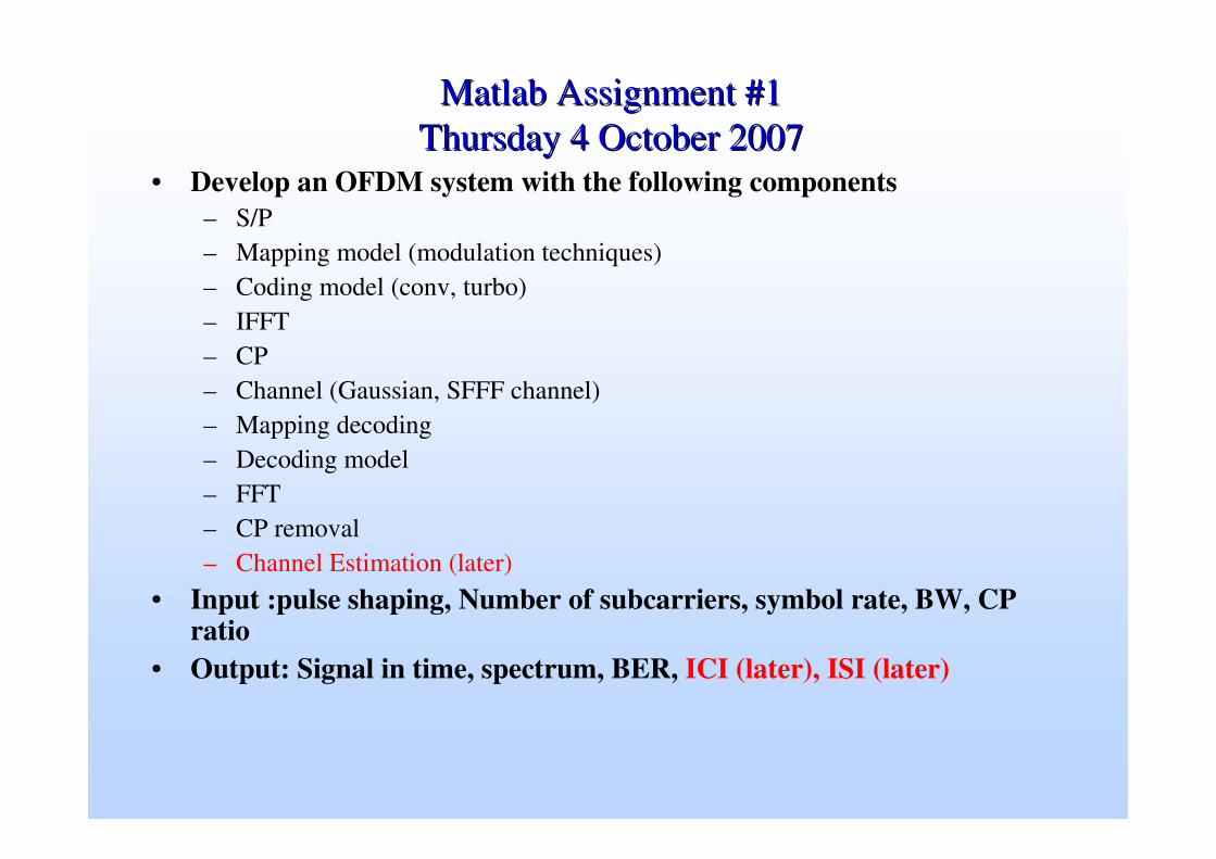
MatlabMatlab Assignment #1Assignment #1Thursday 4 October 2007Thursday 4 October 2007
• Develop an OFDM system with the following components– S/P– Mapping model (modulation techniques)– Coding model (conv, turbo)– IFFT– CP– Channel (Gaussian, SFFF channel)– Mapping decoding– Decoding model– FFT– CP removal– Channel Estimation (later)
• Input :pulse shaping, Number of subcarriers, symbol rate, BW, CP ratio
• Output: Signal in time, spectrum, BER, ICI (later), ISI (later)

HW 2 1/2HW 2 1/2Due Thursday 4 DecemberDue Thursday 4 December
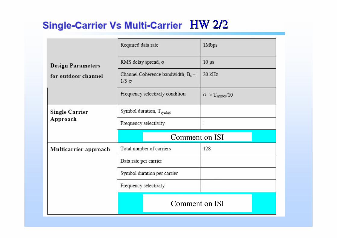
Comment on ISI
Comment on ISI
HW 2/2HW 2/2

Major Learning Objectives Major Learning Objectives
• Upon successful completion of the course the student will be able to:
• Describe the complete architecture of an OFDM system, ( serial to parallel, FFT/IFFT, Cyclic prefix, Modulation techniques, coding techniques)
• Evaluate the response of OFDM in Gaussian channels and fading channels.
• Design and analyze standards using OFDM such as IEEE 802.11a,g and IEEE 802.16
• Define the problems associated of using multi-carrier in time varying channels and how to mitigate these problems.
• Describe the principle mechanisms by which multiple access techniques are supported using OFDM.
• Able to categorize the different type of MC-CDMA and the degree of flexibility provided by each type.
• Able to simulate the basic and advanced techniques used in OFDM systems
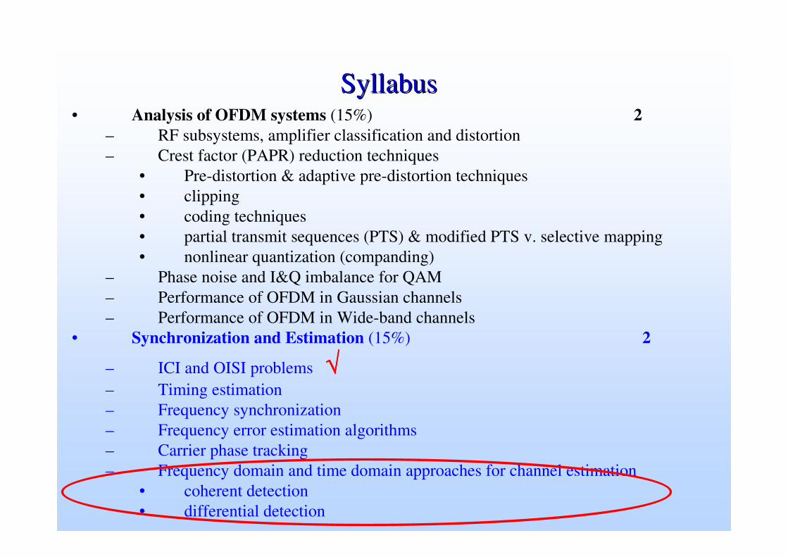
SyllabusSyllabus• Analysis of OFDM systems (15%) 2
– RF subsystems, amplifier classification and distortion– Crest factor (PAPR) reduction techniques
• Pre-distortion & adaptive pre-distortion techniques • clipping • coding techniques • partial transmit sequences (PTS) & modified PTS v. selective mapping • nonlinear quantization (companding)
– Phase noise and I&Q imbalance for QAM – Performance of OFDM in Gaussian channels– Performance of OFDM in Wide-band channels
• Synchronization and Estimation (15%) 2
– ICI and OISI problems √√√√– Timing estimation – Frequency synchronization – Frequency error estimation algorithms – Carrier phase tracking – Frequency domain and time domain approaches for channel estimation
• coherent detection • differential detection
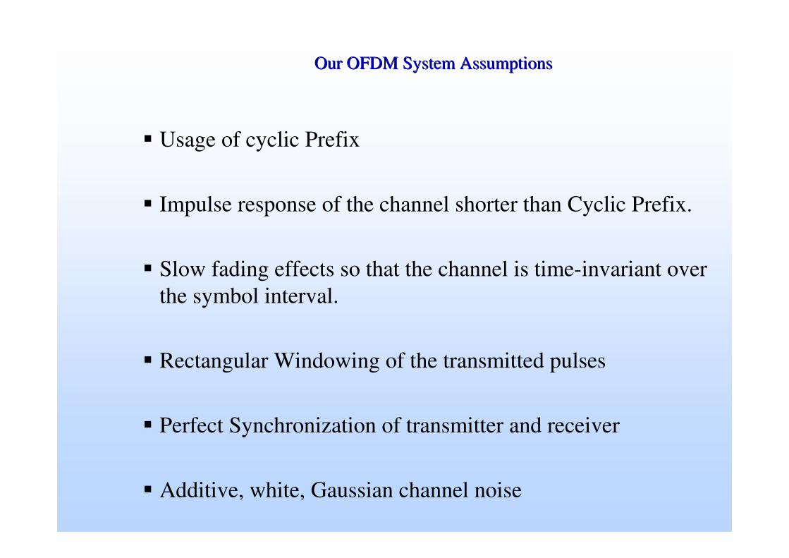
Our OFDM System AssumptionsOur OFDM System Assumptions
� Usage of cyclic Prefix
� Impulse response of the channel shorter than Cyclic Prefix.
� Slow fading effects so that the channel is time-invariant over the symbol interval.
� Rectangular Windowing of the transmitted pulses
� Perfect Synchronization of transmitter and receiver
� Additive, white, Gaussian channel noise
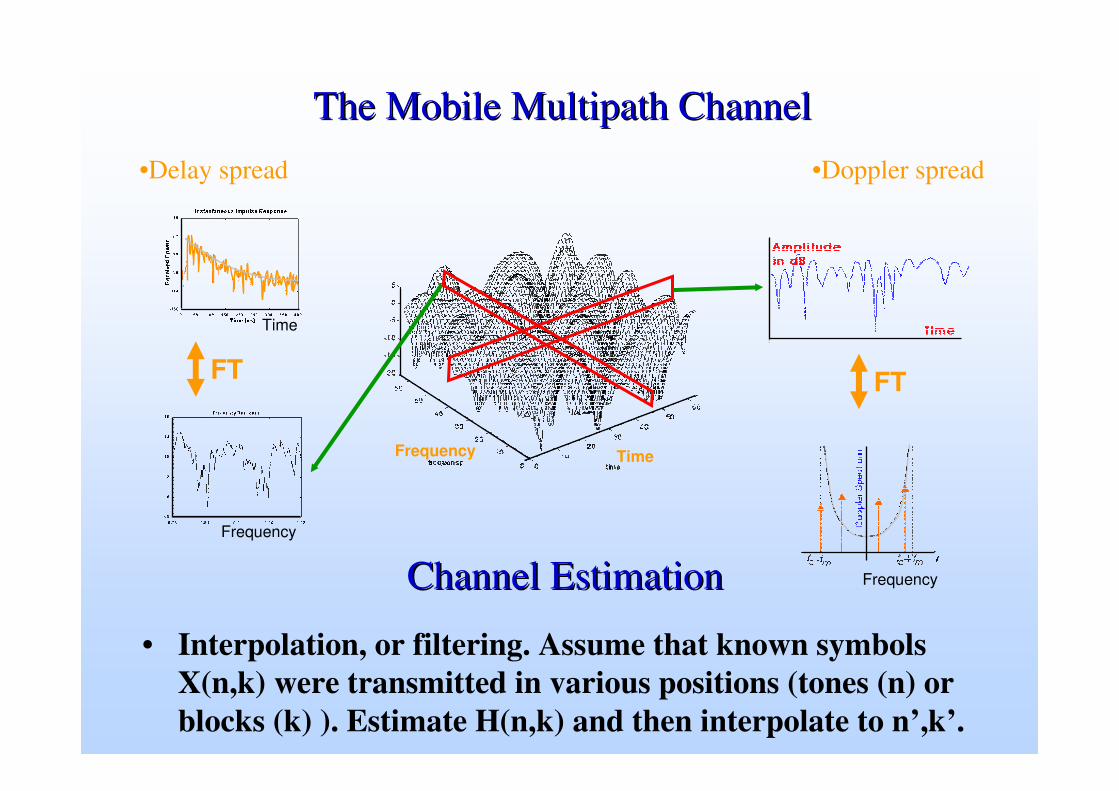
The Mobile The Mobile MultipathMultipath ChannelChannel•Delay spread •Doppler spread
Frequency Time
FT
Frequency
FT
Frequency
Time
Channel Estimation Channel Estimation
• Interpolation, or filtering. Assume that known symbols X(n,k) were transmitted in various positions (tones (n) or blocks (k) ). Estimate H(n,k) and then interpolate to n’,k’.
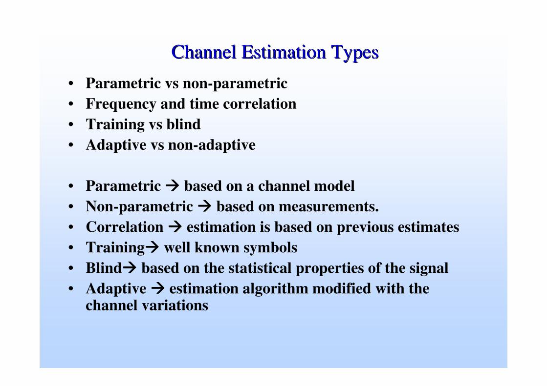
Channel Estimation TypesChannel Estimation Types
• Parametric vs non-parametric• Frequency and time correlation• Training vs blind • Adaptive vs non-adaptive
• Parametric ���� based on a channel model• Non-parametric ���� based on measurements.• Correlation ���� estimation is based on previous estimates• Training���� well known symbols• Blind���� based on the statistical properties of the signal• Adaptive ���� estimation algorithm modified with the
channel variations
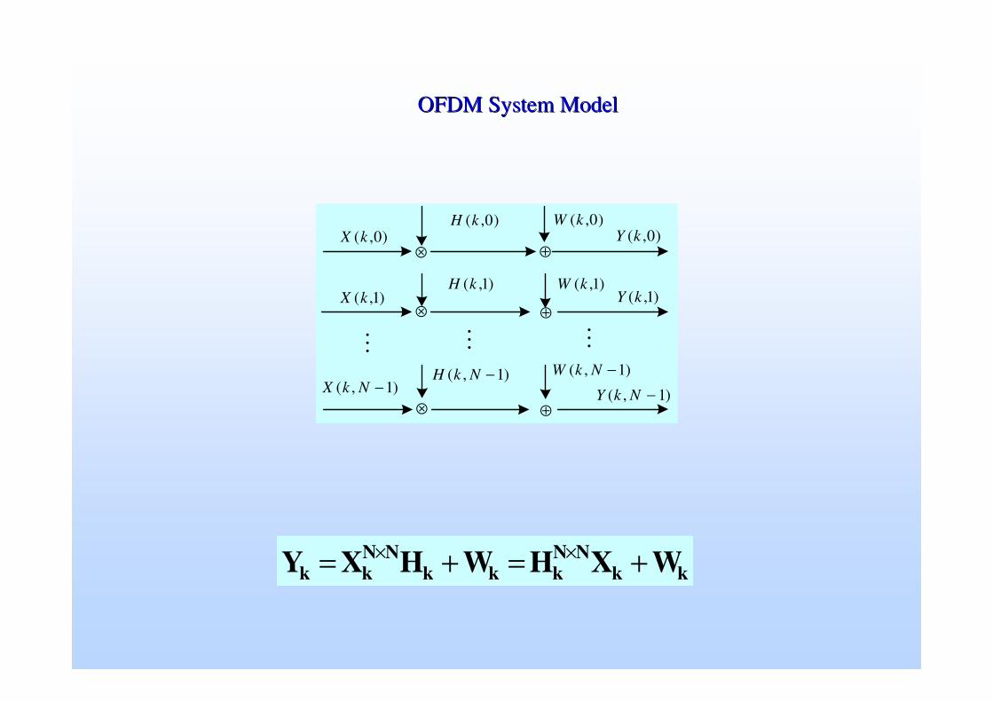
OFDM System ModelOFDM System Model
⊗
⊕⊗
⊕
⊕⊗
)1,( −NkH
)0,(kW)0,(kY
�
)1,(kY
)1,( −NkY
)1,(kW
)1,( −NkW
)0,(kX
)1,(kX)1,(kH
)0,(kH
� �
)1,( −NkX
kkNN
kkkNN
kk WXHWHXY +=+= ××
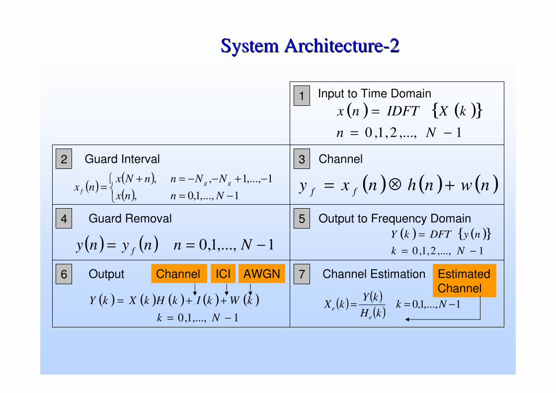
( ) ( ){ }1,...,2,1,0 −=
=Nn
kXIDFTnx
( ) ( )( )�
��
−=−+−−=+
=1,...,1,0,
1,...,1,,Nnnx
NNnnNxnx gg
f ( ) ( ) ( )nwnhnxy ff +⊗=
( ) ( ) 1,...,1,0 −== Nnnyny f
( ) ( ){ }1,...,2,1,0 −=
=Nk
nyDFTkY
( ) ( ) ( ) ( ) ( )1,...,1,0 −=
++=Nk
kWkIkHkXkY ( ) ( )( ) 1,...,1,0 −== NkkH
kYkX
ee
1
76
54
32
System ArchitectureSystem Architecture--22
Input to Time Domain
Guard Interval Channel
Guard Removal Output to Frequency Domain
Output Channel EstimationICI AWGNChannel Estimated Channel

Frequency Domain EqualizationFrequency Domain Equalization
• For the kth carrier:xk = Hk sk + vk
where Hk = �n hk(nTs) exp(j2π k n / N) where n = 0, …,. N-1
• Frequency domain equalizer xk
Hk-1
ssk
• Noise enhancement factor
k
|Hk|2
|Hk-1|2
kgood
bad
Channel EstimationChannel Estimation
• OFDM uses variations of Quadrature Amplitude Modulation (QAM) schemes for symbol mapping which require a coherent detection method in the receiver. – Naturally, data detection in coherent OFDM receivers require an
accurate (or near accurate) estimate of Channel State Information (CSI).
• There are two major kinds of channel estimators that are found in literature:– Pilot assisted.– blind estimation. – A mixture of these two, where a blind method with limited training
symbols is used, is called semi-blind technique.

Types of Channel EstimationTypes of Channel Estimation
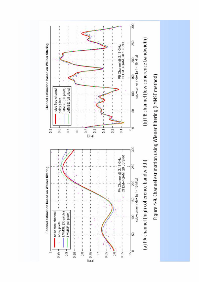
• Traditional one-dimensional channel estimation techniques for the OFDM systems can be summarized as follows: – Least Squares (LS)– Minimum Mean Squared Error (MMSE) – Linear MMSE (LMMSE).
• LS estimators are very simple to constitute, but they suffer from MSE in low SNR conditions.
• MMSE, based on time domain estimations, are high complexity estimators that provide good performance in sampled-spaced channels, but limited performance in non-sample spaced channels and high SNR conditions.
• LMMSE provides good performance in both sampled and non-sampled channels
Channel State InformationChannel State Information
• In OFDM systems, the Doppler effects are kept smaller by making sure that the symbol duration is much smaller compared to the channel coherence time. – In this case, the channel attenuations at successive symbol
durations experience sufficiently higher time correlation.
• Similarly, if subcarrier spacing is chosen in a way that the spacing is much smaller than the coherence bandwidth of the channel– The channel attenuations at the adjacent subcarriers will be highly
frequency correlated.
• So, the estimator can exploit both of these two correlation properties
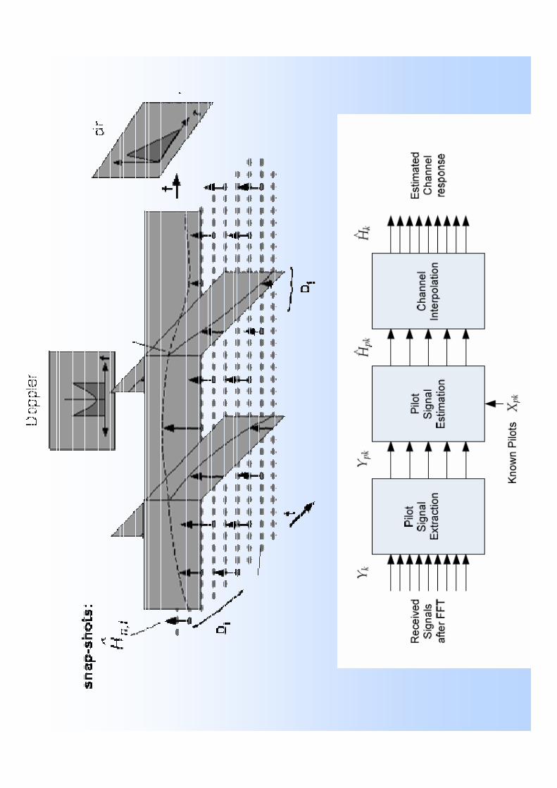
Channel State InformationChannel State Information• Channel estimation of a SISO-OFDM system can be done by using
complete training symbols after certain OFDM data symbols, or byinserting some training pilot tones in every OFDM symbol.
• In the first case, the CSI is estimated with the training symbol and interpolated for the consecutive symbol before the next training symbol appears. – This technique renders unacceptable results when the channel variation
time is comparable to OFDM symbol duration. • The second method is suitable in these kinds of fast varying channels. • The CSI is estimated for all the pilot tones using the pilot subcarriers from
that particular symbol and later CSI for all other subcarriers are obtained by interpolation.
• In that way, perfect or near perfect estimates are achievable. But the cost is paid in significant throughput reduction.

Ideal Channel EstimationIdeal Channel Estimation• Wireless channels change frequently ~ 10 ms• Require frequent channel estimation• The attenuations of the pilot symbols are measured and the attenuations of
the data symbols between these pilot symbols are typically estimated/interpolated using time correlation property of fading channel
• Many systems use pilot tones – known symbols– Given sk, for k = k1, k2, k3, … solve xk = �l=0
L hl e-j2π k l/N sk for hl
– Find Hk = �l=0L hl e-j2π k l / N (significant computation)
• More pilot tones– Better noise resilience– Lower throughput (pilots are not informative)
frequency
mag
nitu
de Pilot tones
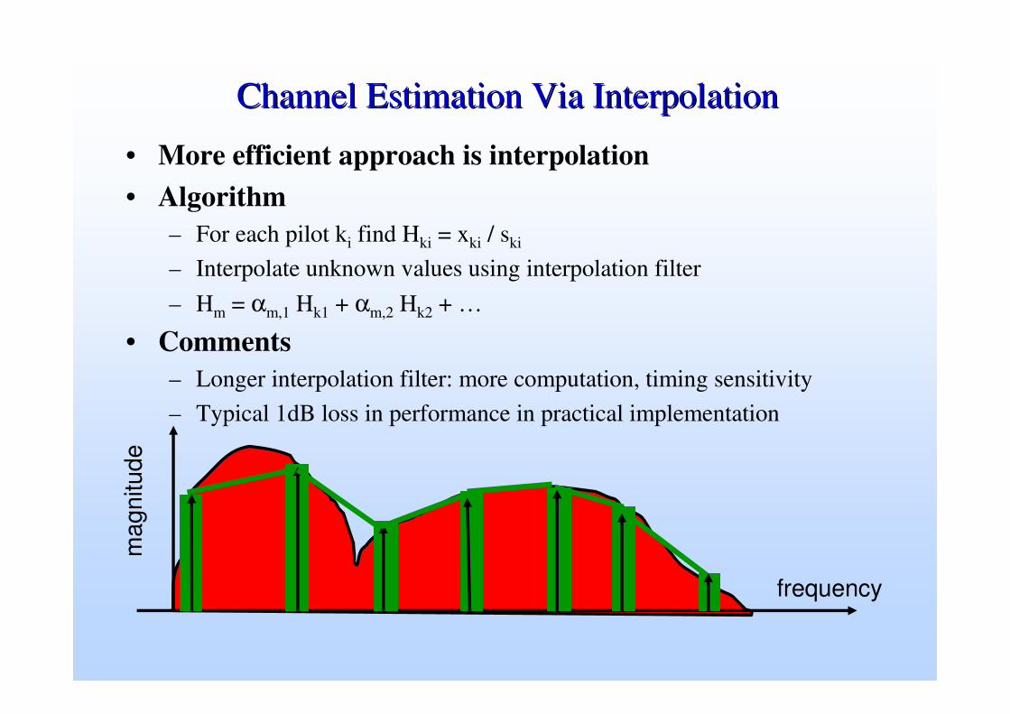
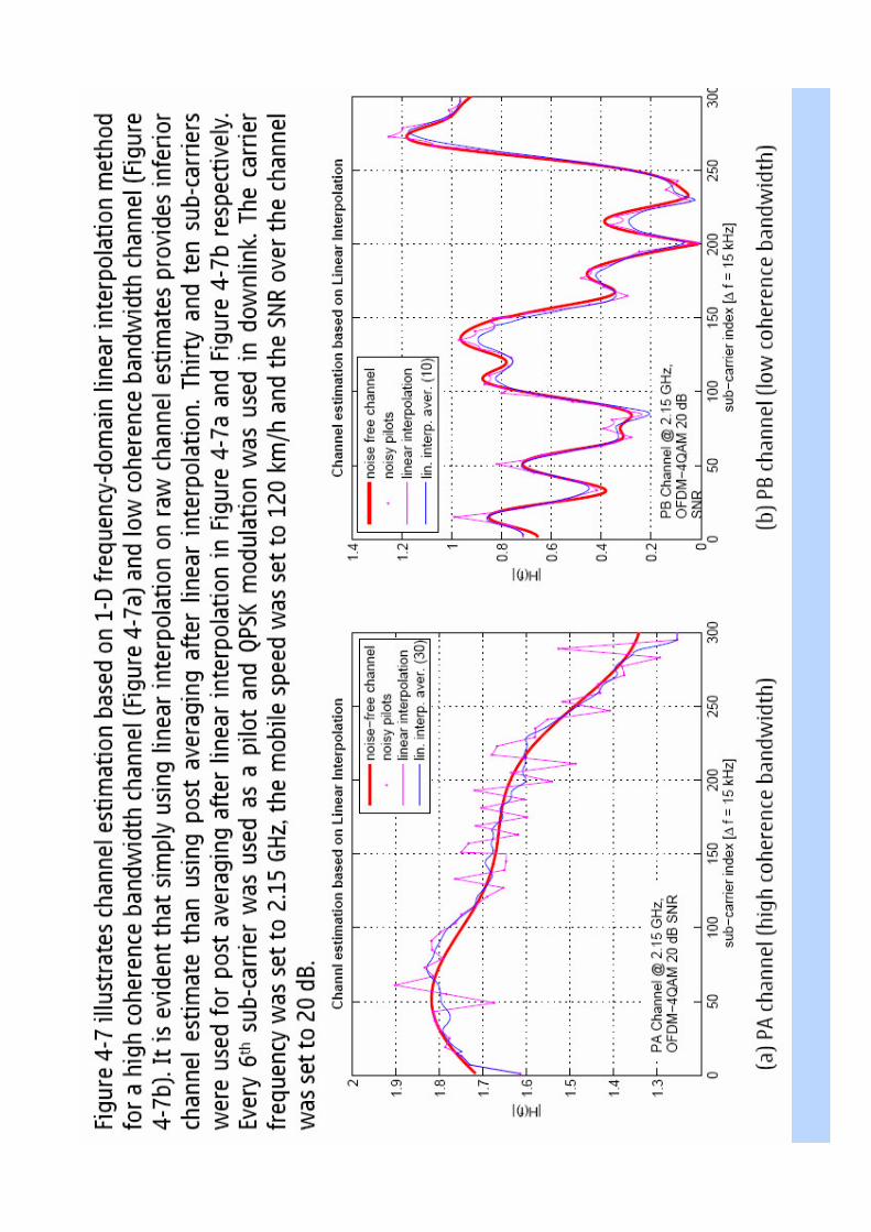
Channel Estimation Via InterpolationChannel Estimation Via Interpolation
• More efficient approach is interpolation• Algorithm
– For each pilot ki find Hki = xki / ski
– Interpolate unknown values using interpolation filter– Hm = αm,1 Hk1 + αm,2 Hk2 + …
• Comments– Longer interpolation filter: more computation, timing sensitivity– Typical 1dB loss in performance in practical implementation
frequency
mag
nitu
de

Channel Estimation algorithm LSChannel Estimation algorithm LS
• In a matrix form, the observed symbols after the DFT operation in the receiver can be written as
• where the diagonal matrix X contains the transmitted symbols on its diagonal (either known pilot symbols or receiver decisions of information symbols which are assumed to be correct), the channel attenuations of one OFDM symbol (i.e. Fourier transform of h(t) evaluated at the frequency fk) is collected in vector h and the vector r contains the observed outputs of the DFT.
• If we maximize the channel estimates in the Least-Square (LS) sense: maximize for all possible
• This is a straight forward estimation technique where the received symbol on each subcarrier is divided by the transmitted symbol to obtain the estimate.
h
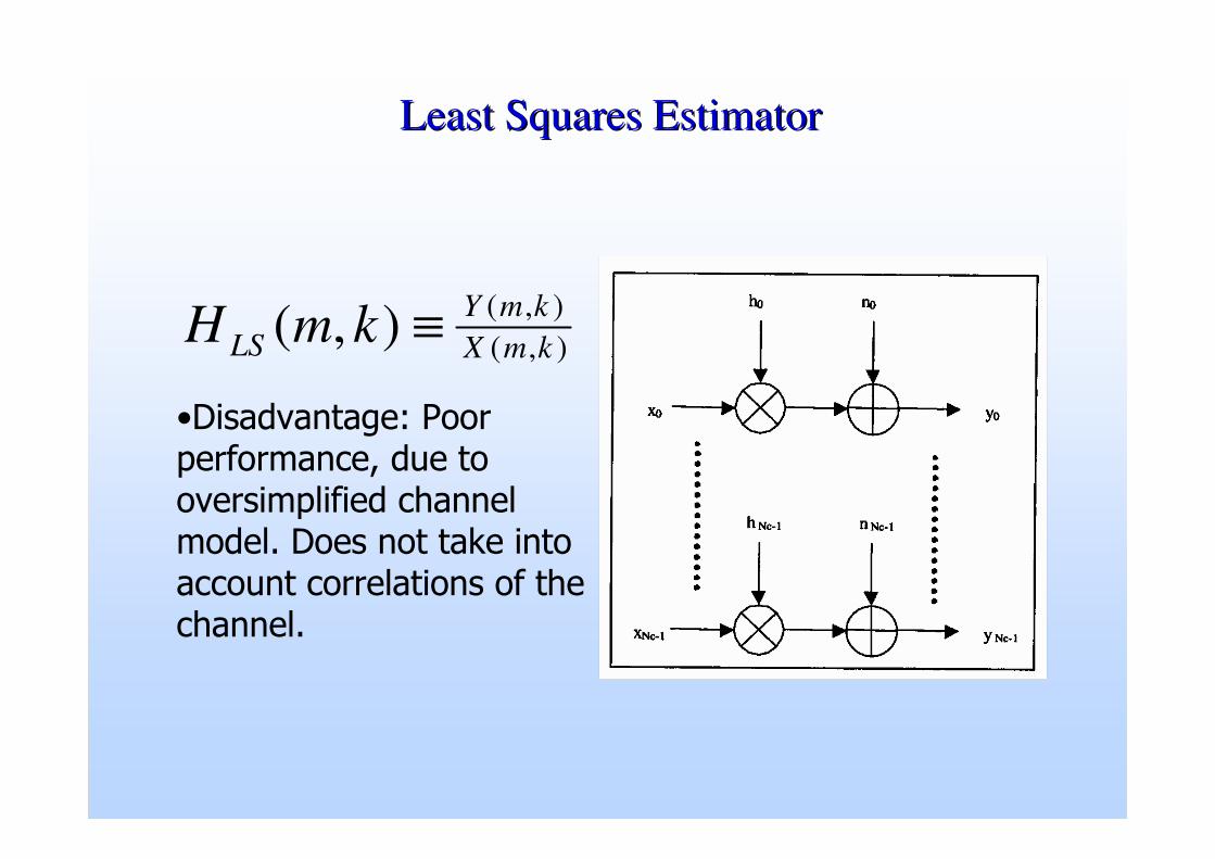
Least Squares EstimatorLeast Squares Estimator
),(),(),( kmX
kmYLS kmH ≡
������������ ���� ������������ ��� � �������������� ������� ������ ���� �� ��� ��� ������ ����������� �� �� ��������

Channel Estimation algorithm LMMSEChannel Estimation algorithm LMMSE
• Minimize the mean square error between the actual channel response and the estimated one by linear transformation to HLS
• The optimal Linear Minimum Mean-Square Error (LMMSE) estimate of by
• (minimizing for all possible linear estimators )
h
h

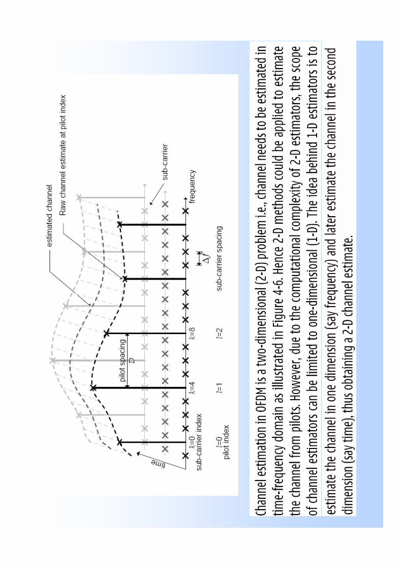
Design of Pilot Based Channel Estimator• There are mainly two problems
in designing channel estimators for wireless OFDM systems. – The first problem concerns
the choice of how pilots should be inserted.
– The second problem is the design of the estimator as a low complexity with good channel tracking ability.
• The pilot symbols should be inserted properly, so that it successfully estimates the frequency response of the channel. The difference between two consecutive pilot symbols in time and frequency domain, Stand Sf respectively, can be represented as
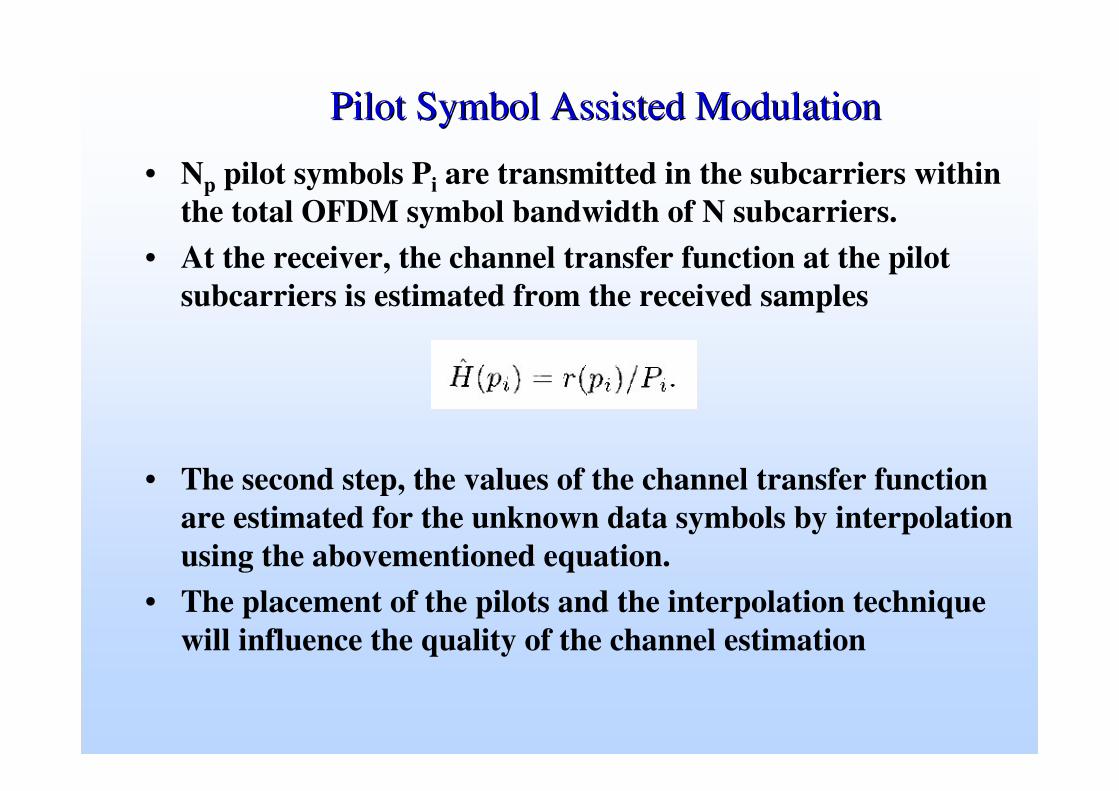
Pilot Symbol Assisted ModulationPilot Symbol Assisted Modulation
• Np pilot symbols Pi are transmitted in the subcarriers within the total OFDM symbol bandwidth of N subcarriers.
• At the receiver, the channel transfer function at the pilot subcarriers is estimated from the received samples
• The second step, the values of the channel transfer function are estimated for the unknown data symbols by interpolation using the abovementioned equation.
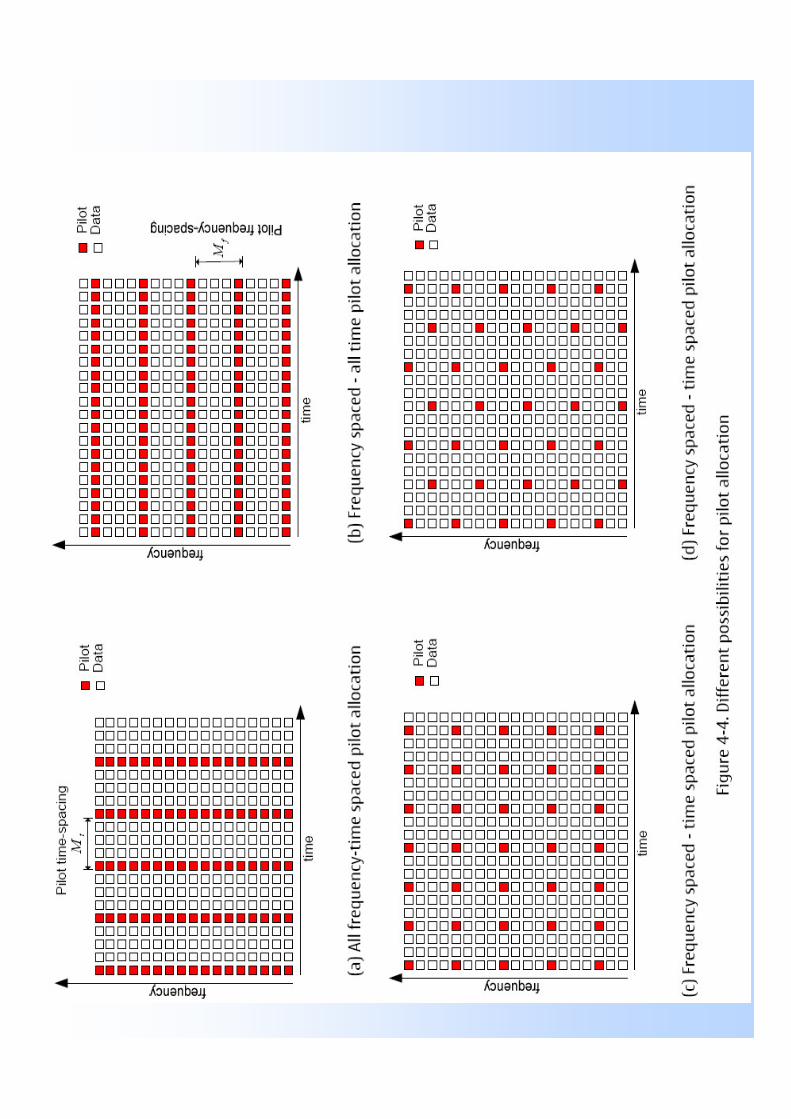
• The placement of the pilots and the interpolation technique will influence the quality of the channel estimation
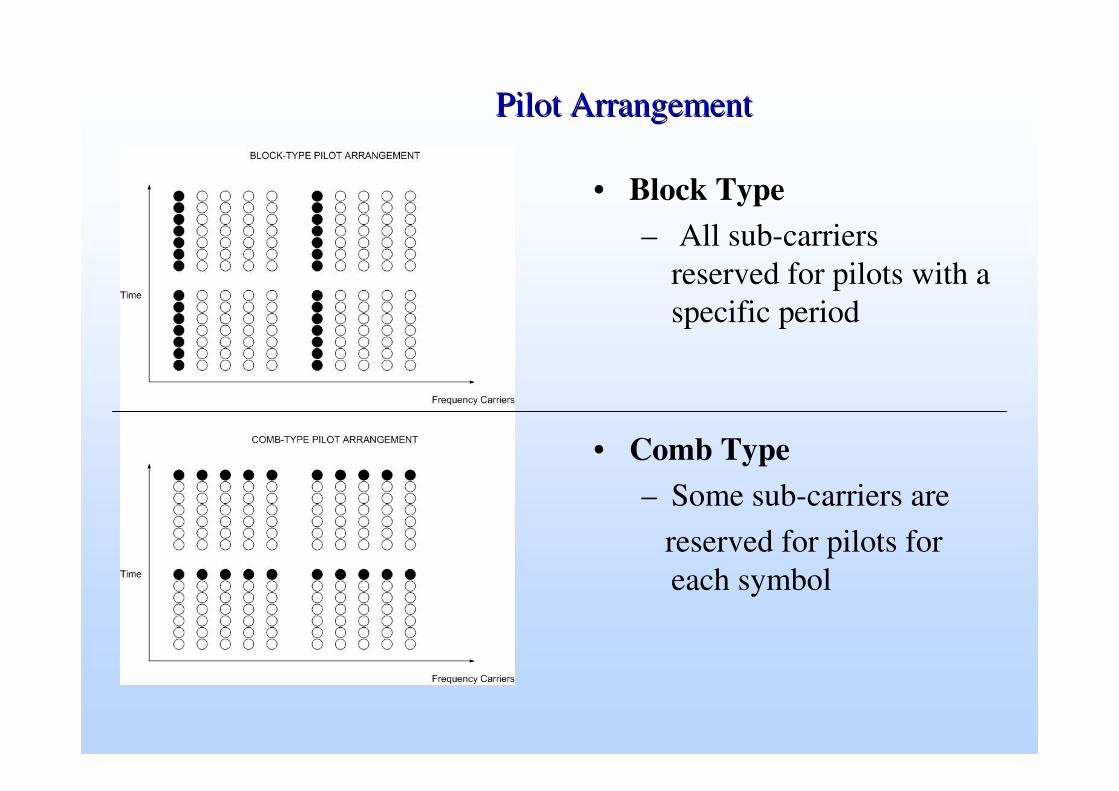
Pilot ArrangementPilot Arrangement
• Block Type– All sub-carriers
reserved for pilots with a specific period
• Comb Type– Some sub-carriers are
reserved for pilots for each symbol
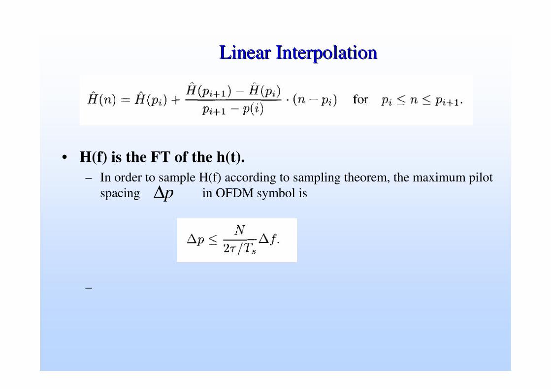
Linear InterpolationLinear Interpolation
• H(f) is the FT of the h(t).– In order to sample H(f) according to sampling theorem, the maximum pilot
spacing in OFDM symbol is
–
p∆

Time domain Channel Estimation using Training Sequence
• Conventional estimation schemes send a stream of transmitted symbols with a modulation scheme known to the receiver, and the receiver analyzes the effect of the channel on the known symbols by observing the deviations on the received known symbols.
• The transmission of training symbols reduces the spectral efficiency of the system

802.11a802.11a System SpecificationSystem Specification
• Sampling (chip) rate: 20MHz• Chip duration: 50ns• Number of FFT points: 64• FFT symbol period: 3.2µµµµs• Cyclic prefix period: 16 chips or 0.8µµµµs
– Typical maximum indoor delay spread < 400ns– OFDM frame length: 80 chips or 4µs– FFT symbol length / OFDM frame length = 4/5
• Modulation scheme– QPSK: 2bits/sample– 16QAM: 4bits/sample– 64QAM: 6bits/sample
• Coding: rate ½ convolutional code with constraint length 7
GI2 T1 GI OFDM Symbol GI OFDM SymbolT2t1 t2 t3 t4 t5 t6 t7 t8 t9 t10
Short training sequence:AGC and frequency offset
Long training sequence:Channel estimation
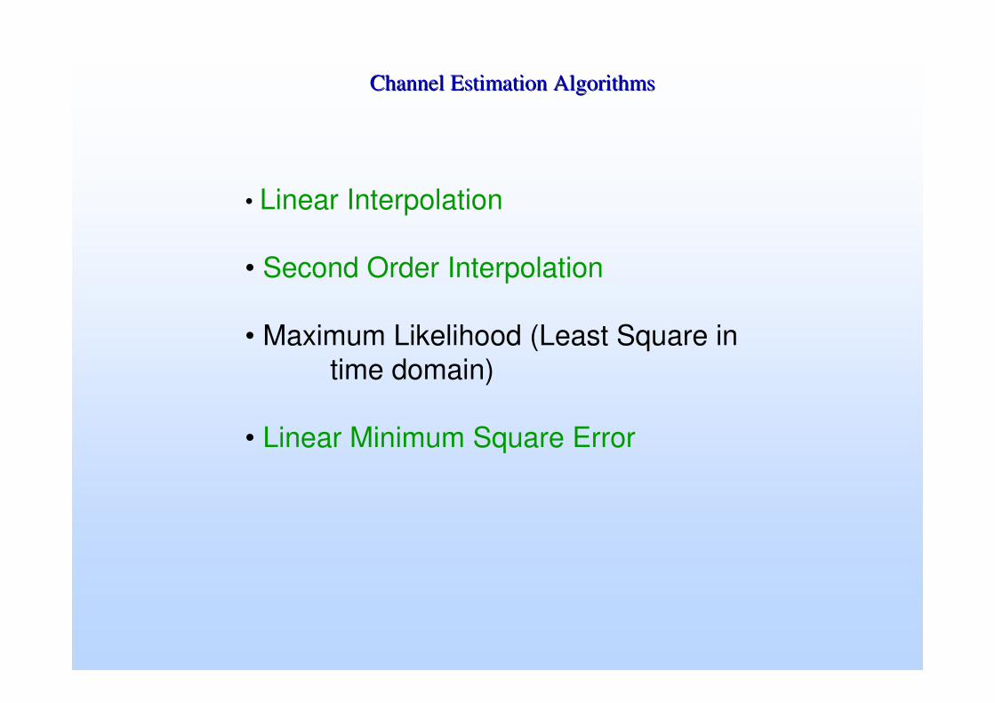
Channel Estimation AlgorithmsChannel Estimation Algorithms
• Linear Interpolation
• Second Order Interpolation
• Maximum Likelihood (Least Square in time domain)
• Linear Minimum Square Error
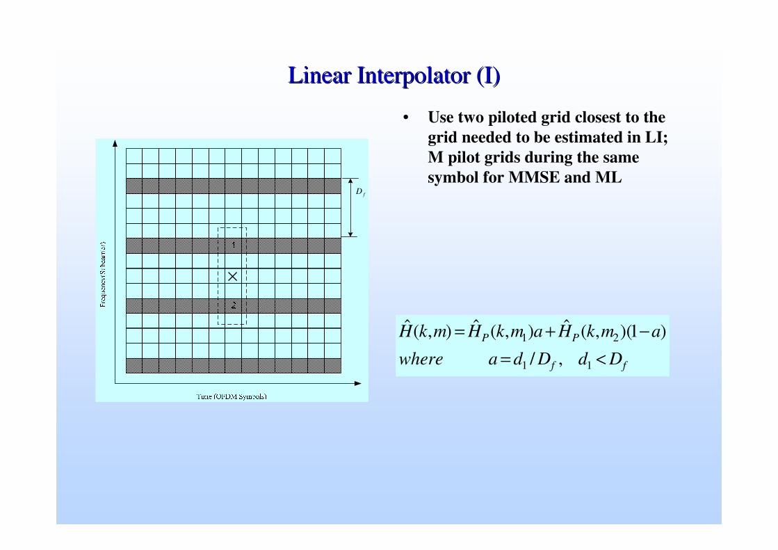
Linear Interpolator (I)Linear Interpolator (I)
• Use two piloted grid closest to the grid needed to be estimated in LI; M pilot grids during the same symbol for MMSE and ML
ff
PP
DdDdawhere
amkHamkHmkH
<=−+=
11
21
,/
)1)(,(ˆ),(ˆ),(ˆ
fD
×

Weighted Linear Interpolator (II)Weighted Linear Interpolator (II)
• Extending linear to weighted linear
����
�
����
�
�
≤<>−
⋅•−
≤≤>−
•
≤≤=−
•
=
+−
−
−
−
+−−
∆
ffK
nK
m
fK
Kn
m
fK
Kn
KnKma
Knma
Knma
nmg
f
f
f
f
f
f
2,1)21(
2)1(
1,1)21(
2
21,1)21(3
2
),(
1
1
1
11
>+−
= mD
mDa
f
fm
f
K
nDmnmg
f
≤≤=�=
∆ 11),(2
1
Where
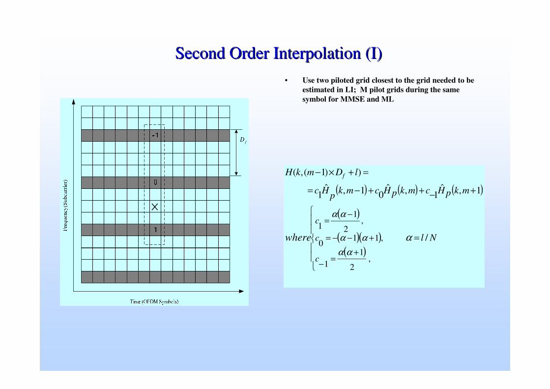
Second Order Interpolation (I)Second Order Interpolation (I)• Use two piloted grid closest to the grid needed to be
estimated in LI; M pilot grids during the same symbol for MMSE and ML
( ) ( ) ( )
( )
( )( )( )
��
�
��
�
�
=
+−++−=
=+×−
+=−
+−−=
−=
Nl
mkpHcmkpHcmkpHc
lDmkH
c
c
c
where
f
/
1,ˆ1,ˆ
01,ˆ1
))1(,(
,2
11
,110
,2
11
ααα
αα
αα
fD
×

Performance of (Simplified) Matrix InversionPerformance of (Simplified) Matrix Inversion
• N = 64, v = 200 km/h, fc = 17 GHz, TRMS = 1 µµµµs, sampling at T = 1µµµµs. • fDoppler = 3.15 kHz, Subc. spacing fsr = 31.25 kHz: • Compare to DVB-T: v = 140 km/h, fc = 800MHz: fdoppler = 100 Hz while fsr = 1.17 kHz
5 10 15 20 25 300
5
10
15
20
25
30
Input SNR
Conventional OFDM MMSE equalization simplified MMSE
k = 4
ConvOFDM
MMSEO
utpu
t SIN
R

MSE MSE vsvs SNR for different gridSNR for different grid

Received and Recovered SignalsReceived and Recovered Signals
�������������� ����������������������������� ��������