monroe l. weber-shirk s chool of civil and environmental engineering dimensional analysis and...
Post on 20-Dec-2015
223 views
TRANSCRIPT

Monroe L. Weber-Shirk School of Civil and
Environmental Engineering
Dimensional Analysis and Similitude
Dimensional Analysis and Similitude
CEE 331
April 18, 2023

Why?
“One does not want to have to show and relate the results for all possible velocities, for all possible geometries, for all possible roughnesses, and for all possible fluids...”
Wilfried Brutsaert in “Horton, Pipe Hydraulics, and the Atmospheric Boundary Layer.” in Bulletin of the American Meteorological Society. 1993.

On Scaling...
“...the writers feel that they would well deserve the flood of criticism which is ever threatening those venturous persons who presume to affirm that the same laws of Nature control the flow of water in the smallest pipes in the laboratory and in the largest supply mains running over hill and dale. In this paper it is aimed to present a few additional arguments which may serve to make such an affirmation appear a little less ridiculous than heretofore.”
Saph and Schoder, 1903

Why?
Suppose I want to build an irrigation canal, one that is bigger than anyone has ever built. How can I determine how big I have to make the canal to get the desired flow rate? Do I have to build a section of the canal and test it?
Suppose I build pumps. Do I have to test the performance of every pump for all speed, flow, fluid, and pressure combinations?

Dimensional Analysis
The case of Frictional Losses in Pipes (NYC)
Dimensions and Units TheoremAssemblage of Dimensionless ParametersDimensionless Parameters in FluidsModel Studies and Similitude

Frictional Losses in Pipescirca 1900
Water distribution systems were being built and enlarged as cities grew rapidly
Design of the distribution systems required knowledge of the head loss in the pipes (The head loss would determine the maximum capacity of the system)
It was a simple observation that head loss in a straight pipe increased as the velocity increased (but head loss wasn’t proportional to velocity).

Two Opposing Theories
agrees with the “law of a falling body”
f varies with velocity and is different for different pipes
Fits the data well for any particular pipe
Every pipe has a different m and n.
What does g have to do with this anyway?
“In fact, some engineers have been led to question whether or not water flows in a pipe according to any definite determinable laws whatsoever.”
Saph and Schoder, 1903
hl is mechanical energy lost to thermal energy expressed as p.e.
2
f2l
l Vh
d g= h mVl
n

h mVln
Research at Cornell!
Augustus Saph and Ernest Schoder under the direction of Professor Gardner Williams
Saph and Schoder had concluded that “there is practically no difference between a 2-in. and a 30-in. pipe.”
Conducted comprehensive experiments on a series of small pipes located in the basement of Lincoln Hall, (the principle building of the College of Civil Engineering)
Chose to analyze their data using ________

Saph and Schoder Conclusions
Oh, and by the way, there is a “critical velocity” below which this equation doesn’t work. The “critical velocity” varies with pipe diameter and with temperature.
Check units...
hl is in ft/1000ft
V is in ft/s
d is in ft
hd
Vl 0.296 to 0.469
1.251.74 to 2.00
Oops!!

The Buckingham Theorem
“in a physical problem including n quantities in which there are m dimensions, the quantities can be arranged into n-m independent dimensionless parameters”
We reduce the number of parameters we need to vary to characterize the problem!

Assemblage of Dimensionless Parameters
Several forces potentially act on a fluidSum of the forces = ma (the inertial force)Inertial force is usually significant in fluids
problems (except some very slow flows) Nondimensionalize all other forces by
creating a ratio with the inertial forceThe magnitudes of the force ratios for a
given problem indicate which forces govern

Force parameterMass (inertia) ______Viscosity ______Gravitational ______Surface Tension ______Elasticity ______Pressure ______
Forces on Fluids
g
p
K
Dependent variable

Ratio of Forces
Create ratios of the various forcesThe magnitude of the ratio will tell us
which forces are most important and which forces could be ignored
Which force shall we use to create the ratios?

Inertia as our Reference Force
F=maFluids problems (except for statics) include
a velocity (V), a dimension of flow (l), and a density ()
Substitute V, l, for the dimensions MLT
Substitute for the dimensions of specific force
F a F
a
f f M
L T2 2
L l T M
fi
lV
l3
Vl
2

Viscous Force
What do I need to multiply viscosity by to obtain dimensions of force/volume?
Cf
fC
LTMTL
M
C22
LTC
1
μ
i
ff
2l
VC
Vlμ
i
ff
ReVlrm
=
Reynolds number
L l Tl
V M l 3
fi Vl
2
2lV
lV 2

Gravitational Force
gC g
g
f
2
22
TLTL
M
Cg
3LM
Cg
g
i
ff
gC
glV 2
g
i
ff Fr
V
gl=
Froude number
L l Tl
V M l 3
fi Vl
2
lV 2
g

Pressure Force
pC p
p
f
2
22
LTMTL
M
C p
LC p
1
p
i
ff
lC p
1
pV 2
p
i
ff 2
2C
Vp
p
Pressure Coefficient
L l Tl
V M l 3
fi Vl
2
lV 2
lp

Dimensionless Parameters
Reynolds Number
Froude Number
Weber Number
Mach Number
Pressure/Drag Coefficients
(dependent parameters that we measure experimentally)
ReVlrm
=
FrV
gl=
( )2
2C p
p
Vr- D
=
lV
W2
cV
M
AVd
2
Drag2C
2fu
Vl
m=
fg gr=
2fls
s=
2
fvE
clr
=
2
fi
Vl
r=
( )p g zrD + D

Problem solving approach
1. Identify relevant forces and any other relevant parameters
2. If inertia is a relevant force, than the non dimensional Re, Fr, W, M numbers can be used
3. If inertia isn’t relevant than create new non dimensional force numbers using the relevant forces
4. Create additional non dimensional terms based on geometry, velocity, or density if there are repeating parameters
5. If the problem uses different repeating variables then substitute (for example d instead of V)
6. Write the functional relationship

Example
The viscosity of a liquid can be determined by measuring the time for a sphere of diameter d to fall a distance L in a cylinder of diameter D. The technique only works if the Reynolds number is less than 1.

Solution
1. viscosity and gravity (buoyancy)
2. Inertia isn’t relevant3.
4.
5. Substitute d/t for V
6.
2fu
Vl
m= fg gr= fbuoy gr=D
2
Dd
P = 3
Ld
P =
1 d gtmr
P =D
,D L
fd gt d dmr
æ ö=è øD
,D L
d gt fd d
m r é ùæ ö= D ê úè øë û
1 2
f
fbuoy
Vgl
m mr
P = =D
1 2
Vgdmr
P =D Water
droplet

Application of Dimensionless Parameters
Pipe FlowPump characterizationModel Studies and Similitude
dams: spillways, turbines, tunnelsharborsriversships...

Example: Pipe Flow
fpC
Inertial
diameter, length, roughness height
Reynolds
l/D
viscous
/D
Re, ,lD D
e
What are the important forces?______, ______, ________. Therefore _________ number and ______________.
What are the important geometric parameters? _________________________Create dimensionless geometric groups
______, ______
Write the functional relationship
pressure
pressure coefficient

Example: Pipe Flow
,Rep
DC f
l Deæ ö=
è ø
f ,Rep
DC f
l Deæ ö æ ö= =
è ø è ø
2
2C
Vp
p Cp proportional to l
f is friction factor
, ,Rep
lC f
D Deæ ö=
è ø
How will the results of dimensional analysis guide our experiments to determine the relationships that govern pipe flow?
If we hold the other two dimensionless parameters constant and increase the length to diameter ratio, how will Cp change?

0.01
0.1
1E+03 1E+04 1E+05 1E+06 1E+07 1E+08Re
fric
tion
fact
or
laminar
0.050.04
0.03
0.020.015
0.010.0080.006
0.004
0.002
0.0010.0008
0.0004
0.0002
0.0001
0.00005
smooth
lD
C pf
D
Each curve one geometryCapillary tube or 24 ft diameter tunnelWhere is temperature?Compare with real data!Where is “critical velocity”?Where do you specify the fluid?At high Reynolds number curves are flat.Frictional Losses in Straight Pipes

What did we gain by using Dimensional Analysis?
Any consistent set of units will workWe don’t have to conduct an experiment on
every single size and type of pipe at every velocity
Our results will even work for different fluids
Our results are universally applicableWe understand the influence of temperature

Same pressure coefficient
Model Studies and Similitude:Scaling Requirements
Mach Reynolds Froude Weber
( )M,Re,Fr,W,geometrypC f=
dynamic similitudegeometric similitude
all linear dimensions must be scaled identicallyroughness must scale
kinematic similitudeconstant ratio of dynamic pressures at corresponding
points ____________________________streamlines must be geometrically similar_______, __________, _________, and _________
numbers must be the same

Relaxed Similitude Requirements
same size
Impossible to have all force ratios the same unless the model is the _____ ____ as the prototype
Need to determine which forces are important and attempt to keep those force ratios the same

Similitude Examples
Open hydraulic structuresShip’s resistanceClosed conduitHydraulic machinery

Scaling in Open Hydraulic Structures
Examples spillways channel transitions weirs
Important Forces inertial forces gravity: from changes in water surface elevation viscous forces (often small relative to inertial forces)
Minimum similitude requirements geometric Froude number
ReVlrm
=
FrV
gl=
Cp is independent of Re

Froude similarityFr
V
gl= p
rm
FrFr = 1
Fr=
rr LV
rr
rr L
VL
t
2/5rrr LLL rrrr LAVQ
3 3rr r r r r r2
r
LF a L L
tm r= = =
difficult to change g
Froude number the same in model and prototype
________________________
define length ratio (usually larger than 1)
velocity ratio
time ratio
discharge ratio
force ratio1
1
1
rFr r
r r
V
g L=

Example: Spillway Model
A 50 cm tall scale model of a proposed 50 m spillway is used to predict prototype flow conditions. If the design flood discharge over the spillway is 20,000 m3/s, what water flow rate should be tested in the model?
000,1002/5 rr LQ
m pFr Fr 100rL
smsm
Qm3
3
2.0000,100
000,20 Re and roughness!

Ship’s Resistance
2
2DragC ,Re,Frd f
V A le
ræ ö= =è ø
gravity
Reynolds Froude
Skin friction ___________Wave drag (free surface effect) ________Therefore we need ________ and ______
similarity
viscosity
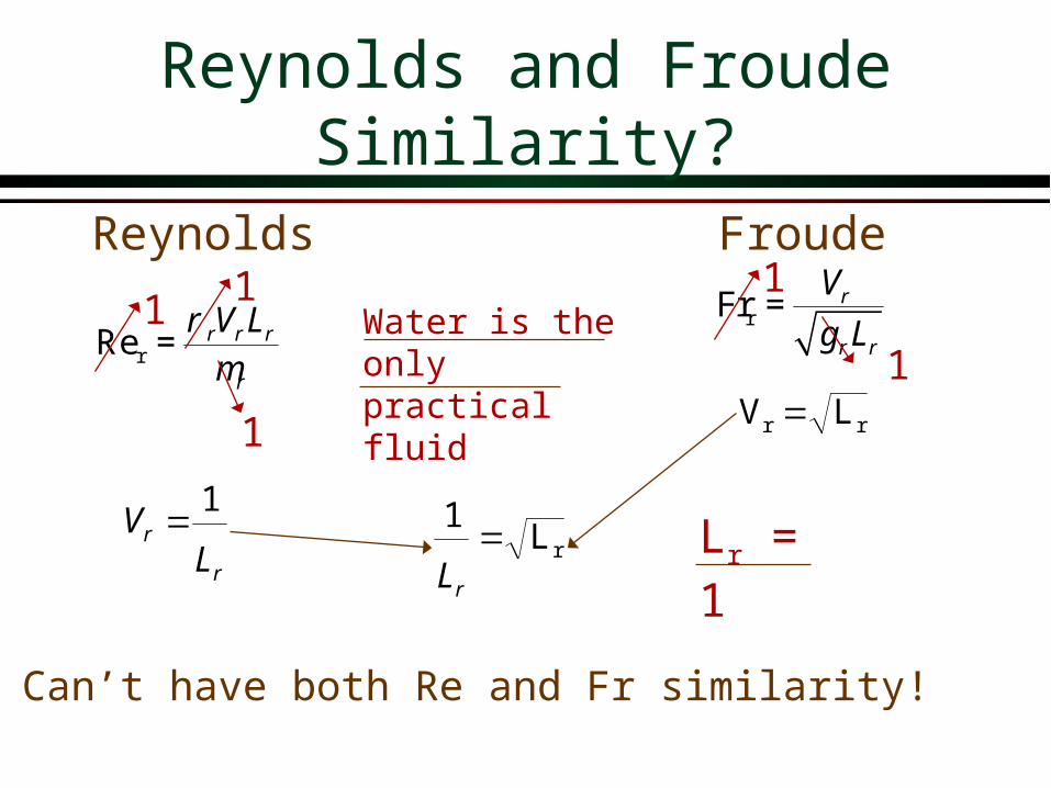
Water is the only practical fluid
Reynolds and Froude Similarity?
rRe r r r
r
V Lrm
=
r
r
LV
1
Reynolds
rL1
rL
rr LV
Froude
Lr = 1
rFr r
r r
V
g L=1
1
11
Can’t have both Re and Fr similarity!
1

Ship’s Resistance
Can’t have both Reynolds and Froude similarity
Froude hypothesis: the two forms of drag are independent
Measure total drag on Ship Use analytical methods to
calculate the skin friction Remainder is wave drag
total2
2DC ,Re,Frd f
V A De
ræ ö= =è ø
( )2
wD Fr2
V Af
r=
2
fD ,Re2
V Af
Dr eæ ö=
è ø
totalD wf DD
empirical
analytical

Closed Conduit Incompressible Flow
viscosityinertia
velocity
Forces__________ __________
If same fluid is used for model and prototypeVD must be the sameResults in high _________ in the model
High Reynolds number (Re) simplificationAt high Re viscous forces are small relative to
inertia and so Re isn’t important
ReVlrm
=

Example: Valve Coefficient
The pressure coefficient, , for a 600-mm-diameter valve is to be determined for 5 ºC water at a maximum velocity of 2.5 m/s. The model is a 60-mm-diameter valve operating with water at 5 ºC. What water velocity is needed?
2
2C
Vp
p

Example: Valve Coefficient
Note: roughness height should scale to keep similar geometry!
Reynolds similarity
rRe r r
r
V Dn
=
m
ppm D
DVV
m
msmVm 06.0
6.0)/5.2(
ν = 1.52 x 10⁻⁶ m2/s
Vm = 25 m/s
Use the same fluid
rRe r r r
r
V Lrm
=

Use water at a higher temperature
Example: Valve Coefficient(Reduce Vm?)
What could we do to reduce the velocity in the model and still get the same high Reynolds number?
ReVlrm
=
ReVDn
=Decrease kinematic viscosityUse a different fluid

Example: Valve Coefficient
Change model fluid to water at 80 ºC
p
pp
m
mmDVDV
mp
ppmm D
DVV
msmx
msmsmxVm 06.0/1052.1
6.0)/5.2(/10367.026
26
νm = ______________
νp = ______________
Vm = 6 m/s
0.367 x 10⁻⁶ m2/s
1.52 x 10⁻⁶ m2/s
rRe r r
r
V Dn
=

Approximate Similitude at High Reynolds Numbers
High Reynolds number means ______ forces are much greater than _______ forces
Pressure coefficient becomes independent of Re for high Re
inertialviscous

Pressure Coefficient for a Venturi Meter
1
10
1E+00 1E+01 1E+02 1E+03 1E+04 1E+05 1E+06
Re
Cp
ReVlrm
=
2
2C
Vp
p
Similar to rough pipes in Moody diagram!

Hydraulic Machinery: Pumps
rr l
V1
streamlines must be geometrically similar
rr lV
Rotational speed of pump or turbine is an additional parameteradditional dimensionless parameter is the ratio
of the rotational speed to the velocity of the water _________________________________
homologous units: velocity vectors scale _____
Now we can’t get same Reynolds Number!Reynolds similarity requiresScale effects
As size decreases viscosity becomes important

Dimensional Analysis Summary
enables us to identify the important parameters in a problem
simplifies our experimental protocol (remember Saph and Schoder!)
does not tell us the coefficients or powers of the dimensionless groups (need to be determined from theory or experiments)
guides experimental work using small models to study large prototypes
Dimensional analysis:
end

100,000
1,000,000
10,000,000
1800 1850 1900 1950 2000
year
popu
latio
n
NYC population
Cro
ton
Cat
skil
l
Del
awar
e
New
Cro
ton

Supply Aqueducts and Tunnels
Catskill Aqueduct
Delaware Tunnel
East Delaware tunnel
West Delaware tunnel
Shandaken Tunnel
Neversink Tunnel

Delaware Aqueduct
10 km
Rondout Reservoir
West Branch
Reservoir

Flow Profile for Delaware Aqueduct
Rondout Reservoir(EL. 256 m)
West Branch Reservoir(EL. 153.4 m)
70.5 km
Hudson River crossing El. -183 m)
Sea Level
(Designed for 39 m3/s)
p Vg
z Hp V
gz H hp t l
11
12
12
222
22 2

Ship’s Resistance: We aren’t done learning yet!
FASTSHIPS may well ferry cargo between the U.S. and Europe as soon as the year 2003. Thanks to an innovative hull design and high-powered propulsion system, FastShips can sail twice as fast as traditional freighters. As a result, valuable cargo should be able to cross the Atlantic Ocean in 4 days.

Port Model A working scale model was used to eliminated danger to boaters from
the "keeper roller" downstream from the diversion structure
http://ogee.hydlab.do.usbr.gov/hs/hs.html

Hoover Dam Spillway
A 1:60 scale hydraulic model of the tunnel spillway at Hoover Dam for investigation of cavitation damage preventing air slots.
http://ogee.hydlab.do.usbr.gov/hs/hs.html

Irrigation Canal Controlshttp://elib.cs.berkeley.edu/cypress.html

Spillways
Frenchman Dam and spillwayLahontan Region (6)

Dams
Dec 01, 1974Cedar Springs Dam, spillway & ReservoirSanta Ana Region (8)

Spillway
Mar 01, 1971Cedar Springs Spillway construction.Santa Ana Region (8)

Kinematic Viscosity
1.00E-07
1.00E-06
1.00E-05
1.00E-04
1.00E-03
mercur
y
carb
on te
trach
loride
water
ethyl
alcoh
ol
kero
sene air
sae 1
0W
SAE 10W
-30
SAE 30
glyce
rine
kine
mat
ic v
isco
sity
20C
(m
2 /s)

Kinematic Viscosity of Water
0.0E+00
5.0E-07
1.0E-06
1.5E-06
2.0E-06
0 20 40 60 80 100
Temperature (C)
Kin
emat
ic V
isco
sity
(m
2 /s)