monsanto research corporation · staff of monsanto/washington university association under thfc...
TRANSCRIPT

'^s T
AD-779 907
MOLDING OF ORIENTED SHORT FIBER COMPOSITES. III. FATE EFFECTS ON FIBER ALIGNMENT iN CONVERGENT CHANNELS
L . A . Goettler
Monsanto Research Corporation
Prepared for:
Office of Naval Research Advanced Research Projects Agency
May 1974
DISTRIBUTED BY:
National Technical Information Service U. S. DEPARTMENT OF COMMERCE 5285 Port Royal Road, Springfield Va. 22151
—V

^7 w^
HPC 72-150 ITEM A002
III.
MOLDING OF ORIENTEF« SHORT FIBER COMPOSITES
RATE EFFECTS ON FIBER ALIGNMENT IN CONVERGENT CHANNELS
by
L. A. GOETTI.ER Monsanto Company
May 1974
D D Ov im
p< .IHN 7 W4 i L
JLiLL^-. i Li:
Monsanto/Washington University Association High Performance Composites Program
Sponsored by ONR and ARPA Contract No. N00014-6 7-C-0218, ARPA Order 876
Approved for Public Release; Distribution Unlimited
Monsanto Research Corporation 800 N. Lindbergh Blvd. St. Louis, Missouri 631G6
il —M~. .
^JV.

i^»-^m ^. IT
St-mrilN Classilicaluin ^/) 7799*7
t$0curltf i InsHification o
DOCUMENT CONTROL DATA - R *. D / „Ho. body ol «(,^ra....,i.)i,../.-..l„:..mloM<i,.nn„,>,l1C jgggj »/„■„ »„■ ..w.r^l r.p,.f> /s r/■■, s.v.f.e./j
, üINATING ACTIVITY (Corporal« au^or)
Monsanto Research Corp,
Zt. REPORT SECURITY C U » S5I E 1 C A T ION
Unclassified 2b. CROUP
Molding of Oriented Short Fiber Composites III. Rate Effects on Fiber Alignment in Convergent Channels
4 DESCRIPTIVE NOTES (Typt ol "■po'l and inclusive dales)
I AUTHORISI CFirsf name, middle miliml, la »I name)
L. A. Goettler
t REPORT DATE
May 1974 ea. CONTRACT OR GRANT NO
N00014-67-C-0218 b. PROJEC T NO
7a. TOTAL NO OF PAGES 7b. NO OF RE FS
17 9a. ORIGINATOR-» REPORT NUMBERIS)
HPC 72-150
9b. OTHER REPORT NrMSI (Any other numben that may be assl«ned thit nporl)
0 DISTRIBUTION ST AT EMENT
Approved for public release; distribution unlimited
II SUPPLEMENTARY NOTES 2 SPONSORING MILI T ARY ACTIVITY
Office of Naval Research Washington, D. C.
1^ ABSTRACT
In an extension of the experiments performed on the compacted flow of a glass fiber-filled epoxy resin through a conical converging channel under a high pressure, this study examines thu orientability of the fibers as the suspension flows into an empty mold cavity. The tensile properties of molded rods of 1/4" to 1/2" diameter reflect the level of orientation produced.
Both the fiber orientability and the resulting orientation distri- bution depend strongly on the rate of elongation. The molded-in orientation distribution is also determined by the extent of conver- gence. Convergence angle, viscosity, and fiber length are secondary variables. The results indicate that fibers can be oriented to within 20° of the flow axis by this technique in order to maximize mechanical performance. The anomalous dependence on the rate of elongation is thought to result from the high voidage in the material during flow.
Reproduced by
NATIONAL TECHNICAL INFORMATION SERVICE U S Departmen» of Commerce
Springfield VA 22151
DD7S?»1473 (PAGE M
S/N 0)01-807-6801 Se-urilv Classification
ii i i alki

^r ^
Security Classification
KEY WO R D»
plunger molding transfer molding flow flow rate elongational flow fiber orientation composite epoxy fiberglass tensile modulus tensile strength convergence flow
DD/rJ473 ••**» ^AGE 2)
ROLE V» T
\(j Security Classification

■ • w^
FOREWORD
The research reported herein was conducted by the
staff of Monsanto/Washington University Association under
thfc sponsorship of the Advanced Research Projects Agency,
Department of Defense, through a contract with the Office
of Naval Research, N00014-67-C-0218 (formerly NOOO]4-86-C-0045),
ARPA Order No. 676, ONR contract authority NR 356-484/4-13-66,
entitled, "Development of High Performance Composites."
The prime contractor is Monsanto Research Corporation.
The Program Manager is Dr. Rolf Buchdahl (Phone 314-694-4721).
The contract ..s funded for $7,000,000 and expires
30 Jure, 1974.
\
■^7 ^^ ^
Molding of Oriented Short Fiber Coruposites
III. Rate Effects on Fiber Alianment in Convergent Channels
by
L, 7 . Goettler
'
ABSTRACT
In an extension of the experiments performed on the
compacted flow of a glass fiber-filled epoxy resin through
a conical converging channel under a high pressure, this
study examines the orientability of the fibers as the
suspension flows into an empty mold cavity. The tensile
properties of molded rods of 1/4" to 1/2" diameter reflect
the level of orientation produced.
Both the fiber orientability and the resulting orientation
distribution depend strongly on the rate of elongation. The
molded-in orientation distribution is a.'.so determined by the
extent of convergence. Convergence angle, viscosity, and
fiber length are secondary variables. The results indicate
that fibers can be oriented Lo within 20° of the flow axis by
this technique in order to maximize m^ nanicai performance.
The anomalous dependence on the rate of elongation is thought
to result from the high voidage in the material during flow.
This research was supported by the Advanced Research Projects
Agency of the Department of Defense and was monitored by the
Office of Naval Research under Contract No. N00014-67-C-0218.
Ml
■■ • ■ *-*-
^MM
^
Molding of Oriented Short Fiber Composites
III. Rate Effects on Fiber Alignment in Convergent Channels
by
L. A. Goettler
V
A polymer melt containing short reinforcing fibers
constitutes an anisotropic fluid that orients in response to
the hydrodynamic forces induced by flow deformation. The
most prominent mechanism for effecting a change in orientation
direction is that of uniaxial extension. This commonly occurs
in ehe stretching of a material, from which it appears
intuitive that the fibers will align along the direction of
stretch. Their rate of rotation in an elongational flow field
can be derived from the mechanics of dilute suspensions of
ellipsoids, as given by (1), by considering the fibers of
aspect ratio 25 to 500 to represent a limiting case of high
ellipticity. Alternately, an equivalent expression can be
derived from considerations of invariance in the constitutive
relationships for anisotropic fluids (2) . In either case, the
rate of orientation change is given by
/dv,
-M dv \ —i- sin 2b, «i/ 1
♦• - 0
(1)
(2)
where 9, is the polar angle of the fiber axis in a spherical
coordinate system whose coordinate axis is in the direction
of stretch.
,1
■ ^V. -—n ■ ■
V^ ■ m9m^^mmmmr^^m9mm^'wm9mmm^^tmmmm^^^^^^m
<t>, iü the corresponding longitude,
dv is the axial velocity gradient at the fiber center. dx.
X is an orientability parameter.
In the case of fiber suspensions in a matrix resin of
viscosity less than 500 noise, like a B-staged cpoxy, conduit
flow is lubricated by a thin layer of resin at the wall so
that the central plug of fibers that encompasses most of the
channel crosb-seccion does not experience any shear (3).
Axial flow through a conical converging channel then becomes
an elongational flow in which the elongatior rate is a function
of axial position alone:
; - **i - Q i 11 ^l Trx^d - cos a) (3)
where Q is the volumetric flow rate.
Substitution of Equation (3) into (1) followed by
integration along a streamline then gives
3X 3 tanO, / x, \ A /, W X
tan0 i / M /A \ix
-0=^) •\&j (4)
- 2 -
II II fclLl
^7 T
where A is the area of a spherical surface of radius X] centered
at the vertex of the cone and subtended by the walls of the
conical channel. For all practical purposes it is equal to the
cross-sectional area of the channel at x^ This equation
applies either to the motioi: of a single fiber or to the
instantaneous collective distribution of the orientations of
all fibers lying along a streamline. It is used in the latter
sense in this paper. Details are given by Goettler (4;.
The channel geometry to which this equation is applied is
shown in Figure 1. The coordinate angles are also identified
in this diagram. Flow is from Imit to right. Further upstream,
and not show: , U a small entrance gate preceded by a runner
system that leads to a plunger chamber. It has been observed
that when angles measured along a streamline are plotted
against axial position in tlie cone for flows of dense materials,
Equation (4) is obeyed. This result also implies that the flow
is sufficiently steady that all fiber orientations measured
along the streamline correspond to the same initial state 6°.
These experiments in which an epoxy/glass fiber molding
compound is caused to flow u^der pressure in a transfer mold
are fully documented elsewhere (4). Since the same materials,
geometry, and analyses are used in the work reported here,
the details will not be repeated.
- 3 -
S
^
<■<*
When not compressed, a 40 v/o suspension of 1/8" long fibers
shows a large amount of voidage due to the high aspect ratio and
stiffness of such fibers. For a three-dimensionally random
material, the maximum fiber content , exclusive of voids, for
packing of the fibers without breaking is about 30 v/o.
This value would be increased if the fibers are bundled or
show some alignment. Injection molding through small gates at
moderate to high rates ten^s to expand the molding compound to
an even lower bulk density until it is compacted in the mold.
At lovver fiber consents of 20-25 v/o, the molding compounds
contain much fewer voids even when not under pressure and
tend to flow more in thr manner of a liquid. Their orientability
is described by the model with constant X even when flowing into
an empty cavity. The pressure drop induced by tho flow itself
is probably sufficient to ca^se whatever voids are present to
close up.
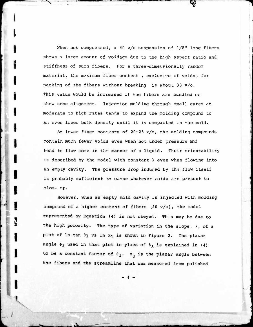
However, when an empty mold cavity ^s injected with molding
compound of a higher content of fibers (40 v/o), the model
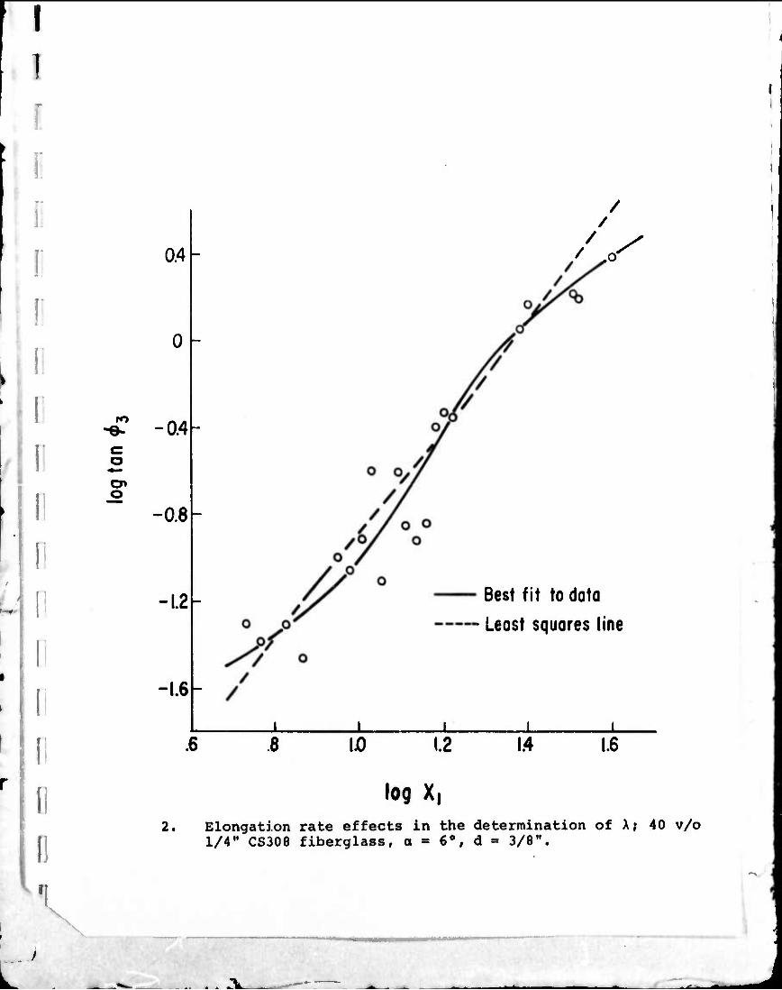
represented by Equation (4) is not obeyed. This may be due to
the high porosity. The type of variation in the slope. A, of a
plot of In tan Bi vs In xj^ is shown iv. Figure 2. The plauar
angle ^3 used in that plot in place of 6T is explained in (4)
to be a constant factor of Q±. <&., is the planar angle between
the fibers and the streamline that was measured from polished
- 4 -
V
-U » J «.Ik.
^P^^^-^I»
^
I I
axial sections cut through the moldings. It represents the
local mean orientation of a close grouping of fibers. The
dashed line in the figure shows how an effective orientability,
X can be fitted by a least squares analysis to the data, eff'
The purpose of this work i^ to study the variation In ^eff'
hereafter simply called X, as a function of material and flow
conditions for those substances investigated in which it is not a
true material constant. Causes for this anomalous behavior and
limitations on X will also be treated. Since, under the proper
conditions, the orientability may increase to very high levels,
the optimum tensile properties of molded rods are compared with
those obtained by other orientation techniques.
Definition of variables.
Equation (4) predicts that the orientation change depends
upon the chanae in cross-sectional area and upon the orientability
parameter, X. This study will center on the effect of elongation
rate, e,, as a function of the volumetric flow rate, Q, the polar
angle of the cone surface, a, and the axial position in the cone,
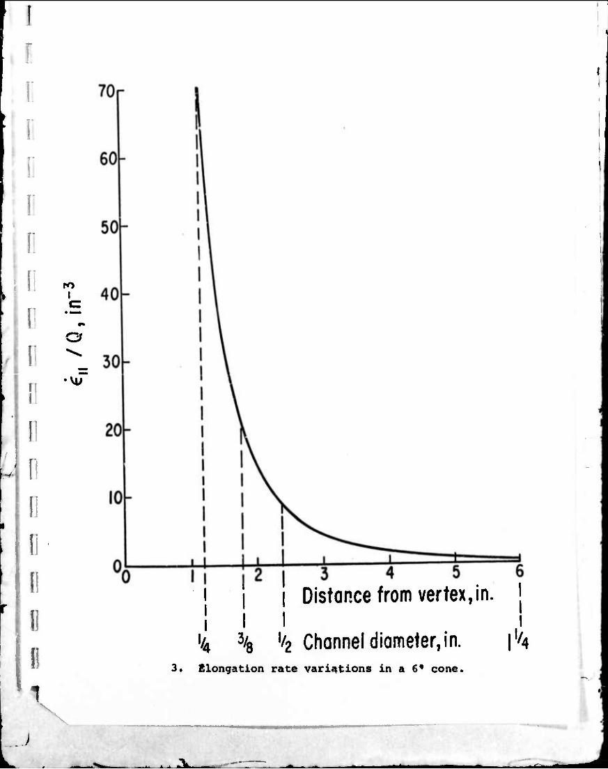
«., A typical variation in e11 with Xj^ is shown in Figure 3
where it is indicated th «t e^ changes rapidly to extremely high
values in the vicinity of the small exit of the cone. For
purposes of correlation with X, it is necessary to define an
average i%\$ denoted e11, for the cone.
- 5 -
X
ii i > alki — t^^^
-^
I V
^
l,in i f •
x. . - x, ,. / Ell l,in l,out < /
f
liOUt
11 X.
y -^/in xl,out \ xl,out /
The average elongation rate is then a function of Q, a, and d,
the cone outlet or attached rod diameter. Values are given in
Table I.
The material variables investigated in this portion of the
study include the individual fiber aspect ratio, £/df, and the
initial bundle aspect ratio, Vdb. Although the bundles are
partially opened by fluid deformation during flow, some integrity
remains, which may influence both the observed orientability, X,
and the mechanical properties of the molded rods. A complete listing
of the parameters affecting the orientation is given in reference
(4), of which this work is a continuation.
The rods of diameters 1/2", 3/8" and 1/4" were filled
directly from the outlet of the conical converging section, as
shown in Figure 1. Because of the low viscosity (< 5,000 poise)
of the epoxy molding compounds, the orientation pattern
produced in the cone was not altered by shear flow in the rod.
Consequently, except for hydrodynamic effects near the juncture
of the two, the tensile propertieF exhibited by the rod should
correspond to the orientability of the material measured in the cone.
- 6 -
V
In these composites. Young's modulus is a strong function of
'-.lie fiber oriei tation and shows little dependence on other
aspects of composite structure. The ultimate properties of
moldings in which the fibers are preferentially oriented into
the stress direction are also predominantly determined by the
degree of fiber alignment. However, when orientation is more
adverse, void content, fiber wet-out and fiber dispersion
become critical (5). Tensile strength, modulus, and ultimate
elongation were measured by mounting the rods in holding blocks
and pulling them on an Instrc-« testing machine. Tensile strain
was measured by an extensometer clipped to the sample surface.
The orientation produced by the cone depends upon the
distribution of fiber angles entering from the large upstream
section. That orientation is nominally transverse in the
center, but it is turned into the direction of flow along the
wall. The average level of orientation in the rods predicted
from measured X-values is based upon the use of an average
upstream orientation angle to represent this distribution.
This average 9° was found to be approximately 77° in all of
the experiments. In the determination of the X-values, on the
other hand, the orientability was measured locally along single
streamlines placed midway between the axis and the wall of
the cone.
Wall Effect
If the center of mass of a fiber lies closer than half the
fiber length to a solid surface, its orientation is biased by
- 7 -
i
physical interaction directly with the wall. The fiber will not
be allowed to assume orientation angles with the wall surface
that are greater than a value depending on the distance of the
centroid from the wall. Orientation consequently tends to
become more "longitudinal," i.e., following the walls of the
channel. This is enhanced by locally high shearing stresses
in the suspension near the wall. Even when the fiber is further
removed from the solid surface, some effacts may still be
transmitted through the oriented fibers that form a boundary
layer in the fluid close to the wall. However, such wall
effects are negligible when applied to overall orientation
obtained in the moldings under study, as long as the channel
diameter exceeds the fiber length.
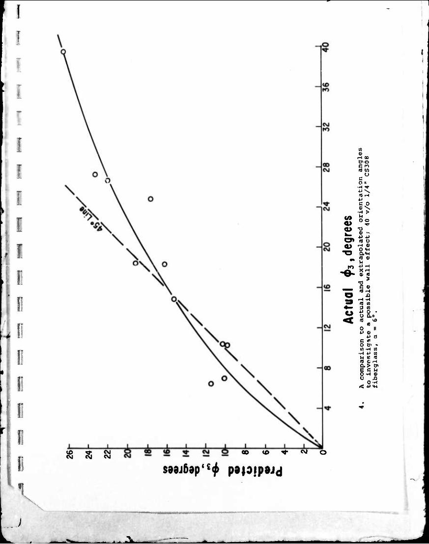
In addition to the evidence presented in (4), Figure 4
shows a plot of two representations of the planar angle 413 at
the downstream end of the cone. The value plotted on the
Ordinate was extrapolated from a regression analysis of the
angle measurements as a function of ax4al position along a
streamline that lies 50% of t-hu radial distance from the axis
to the cone surface. Actual measured values of the downstream
angle from the same samples are plotted as the abscissa. The
different data points in the figure correspond to variations in
the flow rate that caused a changing degree of perfection in
the orientation. Since the wall effect should be greater at
the smaller downstream end of the cone, an agreement between
the extrapolated and measured angles would be taken to indicate
- 8 -
V
^A.

V
the absence of a wall effect. The 45° line in this figure
shows that such equality is indeed very nearly obtained when
the degree of longitudinal orientation is high (4.3 small).
The points at larger 4.3 in Figure 4 corresponds to samples
made with higher flow rates and an accompanying lower orient-
ability. Actual orientation becomes poorer than that predicted
by extrapolation of the axial data. Although this is
unquestionably a flow effect, the observations are contrary
to the influence of the wall.
Other evidence for the absence of a wall effect is the
observed drop in rod stiffness below that predicted on the basis
of the measured orientability of the suspension as rod diameter
decreases. This behavior has been observed (4) for 1/8" fibers
which are always smaller in length than the rod diameters
investigated. Because in smaller rods the area of wall influence
is a much larger proportion of the total cross-sectional area,
the operation of a wall effect would be expected to cause an
increase rather than the observed decrease in the measured
stiffness for small rods.
Correlation of Elongation Rate Effects.
As was mentioned earlier and shown by Equations (3) and (6),
the average elongation rate in the conical converging section is
a function of the flow rate Q, the angle of convergence a, and
the diameter of the cone outlet d, which is also the diameter of
the molded rod attached to the cone. The effective values of
the orientability parameter X were measured as described earlier
_ o -
^^k ^^^

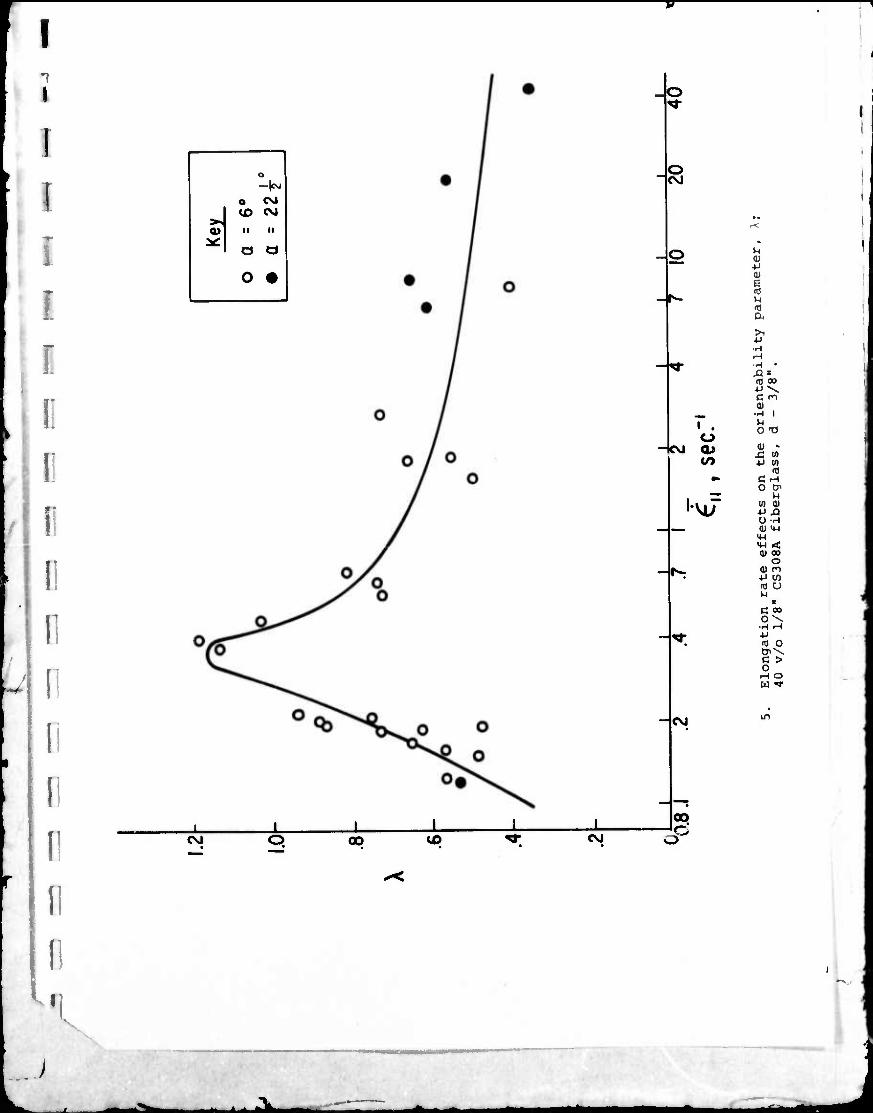
for the flow of a 40 v/o suspension of 1/8" CS308A glass fibers
in an epoxy matrix. Two cone angles of 6° and 22-1/2° were
employed. Average elongation rates are obtained from Table I.
The data plotted in Figure 5 show that X increases for small
increasing elongation rates, passes through a maximum at a critical
elongation rate, denoted by e^, at 0.36 seconds and decreases
at elongation rates above this critical value. The data for the
two cone angles are seen to fall into coincidence on this plot,
showing that the separate effects of flow rate and cone angle can
be combined into a single parameter: elongation rate. It should
be noted that, unlike the case treated in reference (4)for flow
under a compaction pressure, the orientability in this case can
attain values larger than unity at the optimum point.
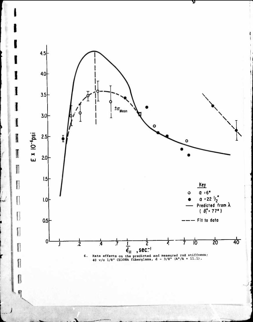
The corresponding modulus measurements on 3/8" dianeter
molded rods are shown as a function of the average elongation
rate in Figure 6. Single data points on this and the preceding
figure refer to individual moldings, except those with range marks
showing the magnitude of the standard deviation of the mean of
several values at that point. The overall reproducibility of the
stiffness measurements for rods molded under similar conditions
is 0.21 x 10 psi. Again it can be seen that the data points on
the 6° and 22-1/2° cones are in agreement when plotted on the
basis of the average elongation rate in the cone. The dashed
curve in the figure represents the best fit to the experimental
data.
- 10 -
-bi ■ i fc^Li
I
The solid curve represents the stiffness that would be
predicted from the model given in Equation (4) utilizing the
measured values of X that have previously been presented in
Figure 5. An upstream angle 0° of 77° is used to calculate the
average angle at the cone exit, or in the rod, which is then
converted into a predicted average rod stiffness according to a
previously determined correlation of experimental data on various
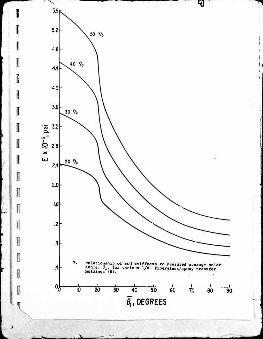
transfer moldings that is given by Figure 7.
Both the predicted and experirental curves pass through a
maximum at the same critical elongation rate of 0.36 seconds
that appears in Figure 5. The experimental and theoretical curves
are ir agreement at an average elongation rate of .15 seconds ,
which was the lowest rate studied. The two curves are again in
coincidence at moderate elongation rates ranging from 1.5 to
15 seconds-1. However, in the decade of rates between .15 and
1.5 seconds-1 there is a large disparity between the predicted
and experimental moduli.
In this range, which contains the optimum elongation rate,
the orientability X is very large, which results in the high
predicted modulus of 4.5 x 10 psi. However, for reasons relating
to the stability of the flow, which will be discussed later, the
actual orientation distribution in the rod is restrained from
reaching the high predicted values. At the very high elongation
rates in excess of 15 seconds- an unexpected jump is observed
in the measured modulus of the rod. This anomaly is not observed
in the measurement of the orientation parameter X. It can be
attributed to a stabilizing effect in the flow which will be
discussed later.
I - 11 -
- ' - ' ———
- J •"'t— m ^ - — ' ■ '-' ■ "*" -J—
\
J

The variations in rod modulus are opposite to effects
attributable to the small variations observed in the upstream
angle 9°. In general, rate dependence of the orientability X
is the overriding effect determining the rr ^.lanic \1 properties
of the molded rods.
The tensile strength of the molded rods shows a similar
dependence upon the elongation rate. However, in this case,
the optimum rate occurs in a value about 4 times higher than
that observed for the stiffness and the orientability parameter.
This can be attributed to the dependence of strength, an ultimate
property, upon factors other than the orientation of the fibers.
For example, the dispersion of the fibers continues to increase
with increasing rate of deformation, and this is beneficial
to the strength. The tensile strength varies from a low value
of 14,000 psi at a rather high elongation rate of 7 seconds"1
to a high value of 28,000 psi at the optimum elongation rats for
strength of 1.5 seconds" . The standard deviation of the mean
for tensile strength measurements is about 1500 psi.
The determinations of the orientability parameter X are
replotted in Figure 8 to show the range of viscosity levels;
as in the case of experiments with flow under a compaction
pressure (4) a normalized apparent Newtonian viscosity is used.
In the study of flow into an empty mold cavity,
the AP over the entire path from ram to vent can be measured
during the flow. Since Pvent is approximately equal to 0, we
take n = k ram The total viscosity changes caused by
variations in the degree of reaction of the epoxy matrix in the
I - 12 -
/ 10
B-stage range over a factor of 67. However, because most of the
data were taken at a constant ram pressure, there is a correlation
between the two variables of flow rate and viscosity. Consequently,
the viscosity range covered at a given flow rate is much smaller
than the total range. This is shown in Figure 8. However, there is
sufficient overlap of runs made at different viscosity levels to
indicate that the behavior of \ is independent of viscosity and
is rather a true function of the flow rate or rate of elongation.
Although not reported here, the measured rod stiffness s^.ows
a similar independence of viscosity. This in in line with the
results obtained with flow under pressure (4) . \ in that
case was a constant independent of Q, but it was also independent
of viscosity over a 25 fold range.
In the case of a 90° entrance angle, a, a dead region will
form in the corners at the point of cross-section reduction.
The flowing fluid will then experience a more gently converging
natural channel that is formed by the stagnant regions. An
effective convergence angle was estimated at about 50° in the
samples, but it likely changes with the fill rate and rheological
properties of the molding compound. (A value of 30° was derived
from pressure drop-convergence angle correlations by Stankoi (6)
for polyester premix.) Because of this, it is not possible to
calculate an elongation rate; the rod stiffuesj can onl> be
correlated against the volumetric rate of flow through the
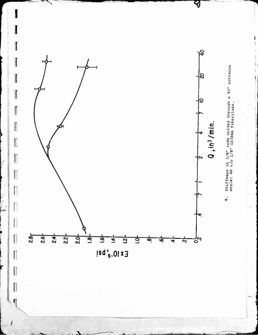
constriction, as ii Figure 9. When multiple measurements at fixed
flow rate were aviliable, the standard deviation of the mean was
indicated by a bracketed vertical line segment.
T
V \
- 13 - ,
^3L. m*m i^b
I
There are several important observations from this graph.
Two overlapping branches result. The flow phenomenon causing
this separation probably has a stochastic nature, rather than
being a deterministic function of the flow or elongation rate.
The lower branch corresponds to the curves discussed previously
for 6° and 22.5° entrance angles, and consequently correlates
with predictions of stiffness from the measured A. For example,
with an effective 50° entrance angle at high flow rates, those
data points can be translated approximately into terms of an
average elongational strain rate and compared with the data
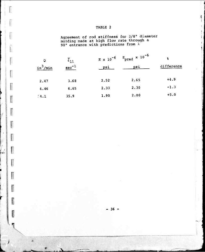
from Figure 6 in Table 2. This good agreement shows that the
lower curve represents the alignment resulting from fiber
rotation in the converging flow. It was not obtained at lower
flow rates with the 90° entrance angle, possibly because of
a change in the character of the flow or a different convergence
angle.
The upper branch in Figure 9 corresponds with the two
isolated points at high elongation rate for the tapered cones
in Figure 6. These results closely coincide in both stiffness
and elongation rates when compared on the basis of a 50°
effective angle frr the 90° entrance. The high level of
stiffness results from an unusually smooth flow that occurs
at very high rates of elongation. This will be discussed later.
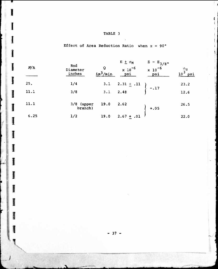
The effect of area reduction ration A0/A, or final rod
diameter, on rod stiffness and strength is given in Table 3 for
the 90° geometry. In this case the degree of alignment is
independent of area reduction ratio at the same value of Q.
- 14-
ii i i *1Li - - ■ ■ j-
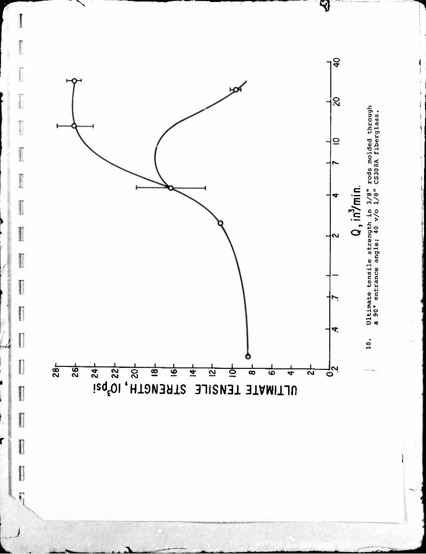
The strength data for the 3/8" rod are represented as
a function of flow rate, Q, in Figure 10. The same two
branches that were observed in the stiffness correlation again
occur. As in the case for a = 6°, the maxima in the strength
curve occur for higher values of 0 or F^, than for stiffness.
The ultimate elongation of the samples was approximately constant
at 1.0%.
It has been seen that the data for cones of different angle
can be superimposed by correlating as a function of the average
elongational strain rate in the cone, ^ni- Similarly, the data
in Figures 11 and 12 in conjunction with Figure 6 show that F,,
can be used as the correlating parameter when the rod diameter
(or cone exit diameter) is changed, keeping the cone angle and
flow rate constant. In each case, the rod stiffness can be
predicted from the single plot of X (?,,) (Figure 5) by using the
experimental relationship of sample stiffness to average axial
angle (Figure 7) that was mentioned previously. These stiffness
predictions are different because the various rods represent
different area reduction ratios (r—) in Equation (4).
In each case, agreement of the experimental data with the
predictions is indicated at both low and at moderately high
elongation rates, but there is a wide discrepancy of 20-30 percent
at the optimum point, ^fn. It appears that T* = 0.36 sec and A
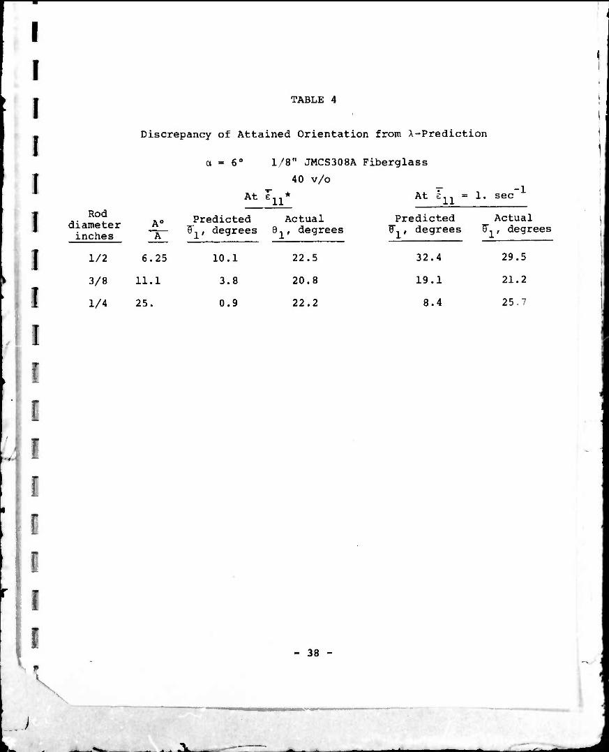
is independent of ^— . Table 4 compares the actual orientation
(calculated from the measured elastic modulus of the rod) to that
predig-,ed from the measured orientability, X, and an initial
- 15 -
V
angle 8° of 77°. In the small (l/M") diameter rods, the
deviation of attained orientation from that anticipated
=>xtends over a wide range, exceeding one decade of extension
rate about the optimum point. For such large area reduction
ratios a high degree of orientation is predicted over a
larger range of X and hence of F-j, than for the larger channels.
It must be concluded from Table 4 that alignments better than
an average angle of about 20° just are not possible in practice.
The effect of reaching a limiting orientation occurs both in
approaching the optimum flow rate and decreasing the channel
diameter. In the case of decreasing rod diameter, the
mechanical prooerties may even degenerate. This is i:hown more
clearly in Table 5 where the comparison for different area
reduction ratios is based on mechanical properties rather
than angles.
For the 1/4" diameter rod, the tensile strength showed
a small general decline from 23,000 to 16,000 psi over the
range of elongation rates of 1. to 200 sec"1. The average of
the measured values was 20,300 psi. This decline roughly
parallels the behavior of the elastic modulus that was
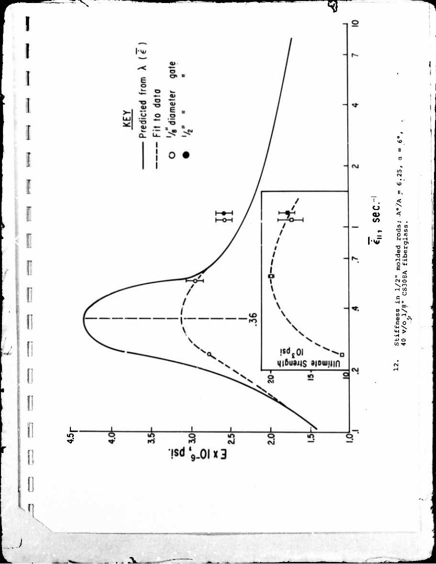
indicated in Figure 11. Strengths of the 1/2" diameter rods
pass through a maximum of 20,000 psi at an average elongation
rate slightly higher than the 0.36 sec"1 observed for modulus,
as shown in the insert in Figure 12. This figure also demon-
strates a lack of dependence on gate diameter, a result also
found in the previous study (4) with flow under pressure.
The ultimate elongation for these samples ranged between 0.6 and 0.9%
V V
- 16 -
JL.

"V
I
Fiber Length
When the fiber length is increased to 1/4", the fiber
orientability, X, shows considerably less variation with
elongation rate than in the case of 1/8" fibers. This is
demonstrated in Figure 13. At e,,, the peak value of X is
only 0.86, which is 25 percent lower than that obtained with
1/8" fibers. The diminished variation in X for the 1/4"
fibers is reflected in the mechanical properties of the molded
rods, which generally show no significant dependence on flow rate.
An exception was observed for the 1/2" rod (A0/A = 6.25),
where the characteristic peak in h occurred at about .36 sec
elongation rate. This is the s.-me critical value of e",, that
was measured for the 1/8" fibers. The modulus and tensile
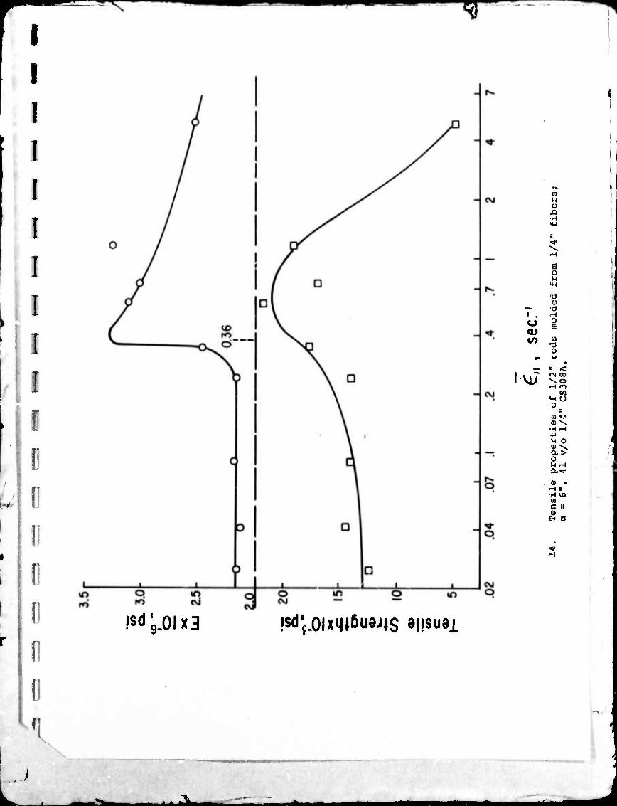
strength data for the V4" fibers are plotted In Figure 14. Over
a large part of the range at the lower elongation rates there is
no apparent variation with eiw because X is essentially constant
in that region. As before, the tensile strength peaks out (at
21,000 psi) at a slightly higher vai.ue of the elongation rate.
The ultimate elongation is constant at .82%. The change in
properties near e,. may have been masked in the rases of the
other rods molded with 1.'1" fibers by impreciaion in the data.
According to the peak X value of 0.86 read from Figure 13,
the predicted rod modulus at .36 sec , the critical elongational
rate, should be 3.2 x 10 psi for the 1/2" rod. That is almost
exactly the value appearing in Figure 14. This calculation
uses an entrance fiber angle, 9° of 77°, as with the 1/8" fibers.
On the other hand, the average measured elastic modulus
- 17 -
V
.*. i i »TL

^r
for 3/8" diametpr rods (A0/A = 11.1) is 3.12 + .07 x 10 pbi at
a fiber content of 44 v/o. This translates to 2.86 x 10 psi
at the standard 40 V/J loading. The corresponding X of 0.61
is almost equcl to the average value of 0.63 measured over the
same range of deformation rates. This result substantiates the
previou.d observation (for 1/8^ fibers) that, when the degree of
alignment is lim' od by a low X value, andrer a small area
reduction ratio the measured stiffness of molded rods can agrte
closely with that p.. .ted from the orientation model. The
ultimate tensile strength and elongation of these moldings are
27,600 psi and 1.1%, respectively.
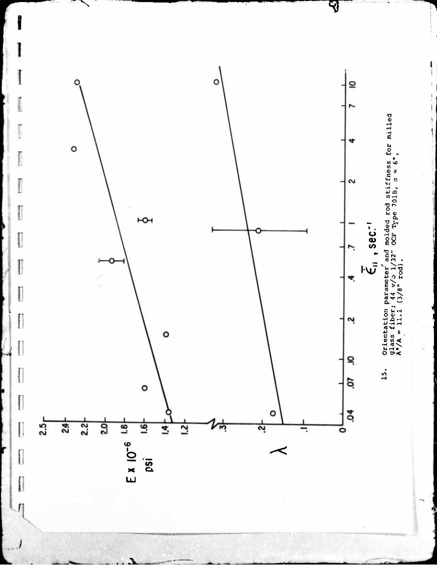
The shorter milled glass fibers show a monotonic increase
in orier.tabiliti with increasing elongation rate. The attendant
increase in red modulus is plotted along with X in Figure 15.
Tensile strength increases slightly from 8,0C0 to 9,000 ps^ with
increasing elongation rate over this range. Reasons for tho
absence of an extremum with this material are presented under
Discussion. Under all conditions, the properties of rods
molded from milled fibers are lower than when longer chopped
fibers are used. Not only do the shorter fibers align more
poorly, as evidenced by their considerably lower X's, but even
in a perfectly aligned composite they would carry only a small
portion of the loai because of their low aspect ratio.
Bundle aspect ratio.
An additional size parameter that was not considered in (4)
is the aspect ratio of the fiber bundles that are incorporated
into the molding compound. Johns Manville chopped glass strand
- 18 -
X
T" ^
it available in two types which supposedly employ the same binder
and differ only in the number of fiber ends. Type 30 8 has 120
filaisnts per strand, while 308A has 24 0. The chopped strand is
coated with a high integrity binder that contains a silane
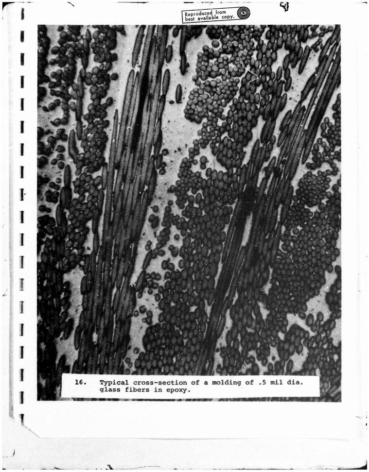
coupling agent and is epoxy compatible. Microscopic examination
of the transfer moldings shows that the degree to which the
bundles of fibers are opened up during the molding operation
depends upon the deformational energy expended, but that in no
case is the bundle completely annihilated. A typical section is
shown in Figure 16. Consequently, the initial bundle aspect
ratij may have some effect or the fiber orientability when the
other geometric variables are held constant.
A comparison of t t moduli of molded 3/8" ro-s using a 6°
converging conical nozzle is shown i-. Table 6 . The sample
standard deviation indicates that there is no significant differ-
ence between the orientation behavior of the two materials. The
ultimate tensile properties, which are also included in the
^ble, support this conclusion.
Discussion
1. Property comparisons
A summary of the molded rod tensile properties is shown in
Table 7. The optimum fiber length is a function of elongation
rate. If the flow rate and geometry can be manipulated to keep
^11 at its critical value of 0.3C sec"1, the v^ry high X for 1/8"
fibers at this point makes them the preferred length. Tensile
^ X
- 19 -
_ :v
i T ^^^^^^
^
1
strength and modulus equal or excel the properties obtained with
1/4" fiber because the higher X allows the 1/8" fibers to orient
into a higher degree of uniaxial alignment.
This result supports the experimental findings of Hoffman
and Fiala (7) working with diallyl phthalate molding compounds.
In a later work Hoffman and Vellturo (8) contend that the
optimum mechanical strength, equalling or exceeding that obtained
from 1/2" fibers in transfer molding, results from the flow-
ability, strand integrity and ability to orient. The latter
factor indicates a high value of A, as we find at Fj^l their
conjecture that screw processing is necessary to obtain highly
oriei 3d moldings, however, is shown to be too restrictive by
the results of this study. Indeed, in properly designed convergent
geometries, very high tensile properties can be obtained in
plunger moldings.
At higher elongation rates, where the X's for 1/8" and 1/4"
fibers are identical (see Figure 13) the 1/4" fibers produce
superior properties. In tre case of the 1/4" rod, this could be
due to a physical interaction with the wall that operates to
preferentially orient the longer 1/4" fibers into the direction
of flow. In a 1/4" rod, the only 1/4" fibers that can occupy a
completely transverse position are those which lie on a diameter.
On the other hand, V8" fibers in 75% of the contained rod volume
could orient in that extreme position. More generally, the flow
with 1/4" fibers could possibly be more stable, or perhaps the
enhancement in mechanical properties could just depend on
- 20 -
V ■■
Al A^i - *■ ^^

^7 ^
structural parameters other than orientation.
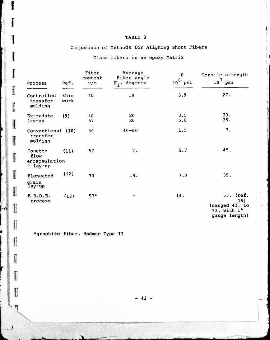
The optimum deoree of alignment and tensile properties
obtained by controlled transfer molding are compared with similar
composites prepared by other techniques in Table 8. Controlled
transfer molding and compression molding of extruded rod prepregs
are similar in that fiber orientation is obtained by a converging
flow in eacn case. Th" first two entries of the table show that
similar properties result. The best possible average polar
angle of fibers about the axis is seen to be about 20°. Phenomena
that contribute to this limitation are discussed below. For
comparison, the very low property levels obtained in a conventional
molding geometry utilizing a small gate at the end of a test bar
are presented as the third entry. Tensile strength is particularly
limited by the transverse fibers in the centers of these moldings.
Higher degrees of orientation can be obtained either with
more sophisticated flow equipment, as in the ERUK process, or by
meticulous laboratory methods. The latter involve the production
of highly elongated grains of individually coated fibers, either
by fiber suspension in a Couette flow field, or by hand-stretching
a mass of fibers that has been impregnated with resin. The
B-staged grains are then hand laid into cavities and compression
molded. These techniques produce high property levels, with
average angles at about 10°, but are not amenable to large scale
production. The ERDE process is used to produce a commercial
graphite fiber/epoxy prepreg. It employs a special moving
trough to deposit short fibers suspended in a low viscosity
- 21 -
V
-u I I »\

^N "■^■■Ä^-—^^^^■»■^»•^•^^ ^
solvent into an aligned mat. The flow field at the trough exit
is a type of elongational flow. Tensile data are available only
for compression moldings of graphite fiber prepregs. Taking
into account the differential in stiffness between glass and
graphite fibers, the reported properties in Table 8 indicate an
improvement over the extrusions and transfer moldings that is
slight in modulus, but significant in tensile strength.
2. Orientation behavior
At the same fiber content (40 v/o), higher orientabilities
(up to X = 1.2 for 1/8 fibers) are measured in this wor-c than
can be realized when the material is compacted under several
thousand psi before flow occurs. Then the measured X is only
0.47. When molding into an empty mold cavity, the void content
in the molding compound is high. By stopping the flow when the
cavity is only part filled, the noncompacted material can be
cured and then removed for examination. The high void contents
exceeding 10% found in these "short shots" compare with 2-3% in the
completed moldings. Such a high voidage could give an increased
mobility to the fibers and hence the higher value of X. This
would be similar to the effects of free volume on a molecular level.
Other evidence exists to support the hypothesis that it is
the rotational mobility of the fibers that determines the value
of X. The peak X of 0.86 read from Figure 13 for 1/4" fibers
1
I I
!
1 I
- 22 -
^r
\
F r II l"
is 26% below the peak for the shorter 1/8" fibers. Bee ase of
their larger length, they interact and tend to bend and tangle
to a higher degree; hence, they have a lower mobility. If
fiber length is decreased too much, however, X will decrease
to low values, as in the case of the milled fibers. When
fibers are too short the hydrodynamic forces causing the fiber
rotation are not fully develr .3d. The opposing requirements of a
sufficiently long fiber to realize the maximum forces and a
sufficiently short fiber to minimize fiber interactions are
compromised in the optimum fiber length of 1/8".
In (4) it was found that, with compacted material, a
decrease in the fiber content causes an increase in X. The
orientability increases from 0.47 to 0.75 as the concentration
of fibers is halved to 20 v/o. At the lower concentration, there
is a lower degree of fiber interaction, resulting in a higher
mobility.
Let us now consider the reasons for the variation of the
orientability, X, and the molded mechanical properties with the
rate of elongation. Attention will be focused on the results
for a = 6°, d = 3/8", 40 v/o of 1/8" fibers, given in Figures
5 and 6. There are three different regimes of flow to be considered;
i) low T,. (< 0.36 sec" ), where X and E increase with
increasing elongation rate
-1,
N.
ii) moderate F,, (0.36 < 1^ < 10 sec ) where X and E
decrease with increasing elongation rate
iii) high F,, (> 10 sec" ), where an abrupt increase in E
is observed.
- 23 -
.n i i >1LI

-N ^
The flow behavior in these regions is influenced by the granular
structure of the molding compound, as well as the high voidage,
which causes the material to be inhomogeneous.
Only the molding compounds made from 1/8" or longer fibers
at a high loading, 40 v/o, demonstrate the anomalous dependence
of orientation on elongation rate. These materials in the
noncompacted condition consist of well-defin^ grains, each
consisting of numerous fiber bundles held tightly together with
a thin coating of resin. The structure during fill for a highly
expanded material is shown in Figure 17. When shorter fibers or
a lower fiber loading (excess resin) are employed, such distinct
grains do not form.
At very low flow rates, Takano (14) and Hagan and Thomas (15)
have observed that the flow of a concentrated fiber suspension
through a small orifice may be intermittent. Although this may
not actually occur in the wider channels of our experiments, the
slow flows are thought to be locally nonuniform. The meshing
together of the granular units as the cross-sectional area is reduced
will cause an alternating movement between different regions of
the cross-section. Secondary flows may also occur. The resulting
swirled and oscillatory orientation patterns cause not only a
strong local fluctuation in the measured angle (ji-j over small
distances, but also reduce the distance-averaged orientation
parameter X.
In regime i), as the elongation rate increases up to tne
optimum value of 0.36 sec , the flow becomes smoother because
the higher orienting stress can more easily overcome the flow
- 24 -

^N -?^i ^
\
resistance of the grains. At the same time, the void content
is increasing slightly.
Beyond the maximum point and into regime ii), it is
believed that X is reduced by hydrodynamic instabilities in the
flow that become significant only at the higher elongation rates.
Some typical oscillations of the planar angle $3 measured in the
cone are shown in Figure 18. The scale of these oscillations is
much larger than the grain size shown previously in Figure 17.
Since the elongation rate increases rapidly near the cone exit,
and since a discontinuity in the streamline direction also
exists at the cone-to-rod juncture, the instabilities are
probably more severe at that point and limit the orientation in
the rod to the 20° range, regardless of the degree of orientation
predicted from the X values. The occurrence of wild oscillations
at the rod entrance and their continued existence, though at a
reduced amplitude, into the rod is shown in Figure 19.
In the first two orientation regimes, then, the orientation
in the rod is controlled by the size of the orientation parameter,
X, which itself is hypothesized to depend on flow disturbances of
two types. On the other hand, the third regime, which is defined
by F,, > 10. sec is characterized by a sharp increase in the
rod stiffness that is not accompanied by a corresponding increase
in the measured X, but rather by a decrease in the local angle
fluctuations. The increase in smoothness of the flow is
dramatically shown by a comparison of the two axial orientation
profiles in a 22-1/2° cone measured above and below the critical
• 25 -
->
A.

^r •^p
^
i
7 for transition to the third regime, in parts a and b of 11
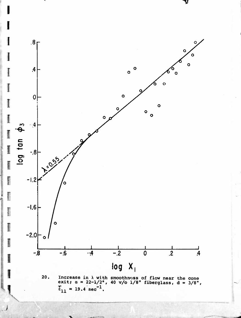
Figure 18. The high rod rigidity at a relatively low average X
for the cone is possible through a sharp local increase in X in
the very high elongational strain rate that exists near the cone
exit. The behavior is illustrated in Figure 20. It occurs only
at very high local rates of strain {> about 60. sec" ) and is
accompanied by a smooth and stable orientation pattern. Rod
properties in this regime are controlled by conditions at the
cone-rod junction rather than by the overall orientation
behavior in x:he cone.
One could hypothesize that the critical alongation rate
for entrance into regime Hi) corresponds to the point at which
the fiber network fractures, thus relieving built-up elastic
stresses that tend to resist orientation change. This conjecture
is supported by the absence of a maximum point in the X and
mechanical property data for milled fibers. Such short fibers
would not be capable of forming an interpenetrating network that
could sustain an elastic force. Consequently, the memory of
these materials is nonexistant, oscillatory orientation patterns
do not occur, and the orientation continues to improve, though
slowly, into better axial alignment as 1^ increases. However,
the flow of the milled glass suspensions is complicated because
their lower structure may also allow substantial shear to occur.
- 26 -
X -r*.-
r I * fcl
-^7 ^
I
For the 90° entrance angle, reqimes ii and iii overlap.
j It has been shown that a very high ^iongat.ton rate is required
to enter iii. A change in the elongation rate at the same flow
I rate and 90° geometry can be due to a movement of the natural
channel boundary that separates the flowing portion from the
stagnant region at the corners. Visual obüervation of polished
sections of the entrance region show that the higher tiffness
of the upper-branch in Figure 9 is associated with smaller
oscillations in the rod, especially at the centerline, and that
these, in turn, occur when the stagnant region is smaller.
Periodic plugging of the rod entrance would also be a likely
flow disturbance when a = 90°, particularly for the smallest
diameter rod.
The orientation and consequent mechanical properties in
molded rods thus depend upon two causative phenomena. These
are the average rate of orientation change in the converging
section preceding the rod, which can be correlated with the
average rate of elongational strain in that section, and
entrance effects at the cone - rod juncture. The latter depend
upon the locally high elongation rate there and are associated
with a sharp increase in the smoothness of the axial orientation
profiles. This decrease in the short-range variations of
orientation is probably a requisite for the enhanced rigidity
observed in regime iii).
I - 27 -
— II.
• • - ^ ^^^^b-MM^MMMV
^N ^
Conclusions and Summary.
When a polymer containing a high concentration of moderately
long (> 1/8") discontinuous fibers flows into an empty cavity
the porosity is high (> 10%) and the orientability parameter, X,
in the equation
tan 6 tan ö
1
is not a constant but depends on the rate of elongation in an
extensional flow. At the optimum rate of elongation A takes
on a maximum value of 1.16. High voidage results from an
upstream diverging channel, such as would be produced by a small
gate. If no such region exists above a converging channel, X
might be expected to be a constant, equivalent to that obtained
in flow under a compaction pressure (4).
In that case, a relatively low value of .47 results for X,
because the mobility of the fibers is more restricted. Mobility
is increased in suspensions of lower fiber content, because of
less severe fiber interaction. It increases to .63 at 20 v/o.
Reducing the fiber length might also be expected to lead to a
lower interaction. However, X is reduced if the fibers are too
short (< 1/32"), because the hydrodynamic forces causing the
rotation cannot act as effectively. On the other hand, increasing
fiber length from 1/8" to 1/4" causes a decrease in the maximum
X for low density flows from 1.16 to 0.86. The bending and
tangling of the longer fibers inhibits their rotation. 1/8" is
the optimum fiber length.
- 28 -

-T^H»!
^
I 1 I I I I I !
I
The highest degree of longitudinal orientation that can be
obtained in a practical elongational flow of 1/8" or longer fibers
in an epoxy matrix is characterized by an average angle of 20°.
However, this represents a significant improvement over conventional
molding practice, wherein an end-gated part contains a central
core of transverse fiber orientation. Tensile strength can be
increased more than threefold fro.u 7,000 to 27,000 psi and
modulus from 1.5 to 3.9 x 10⁶ psi by instituting the proper
control of orientation.
The limitation« on orientability, X, and on the actual
orientation distribution produced in a rod molded through a
converging section are hypothesized to result from inhomogeneous
movement and fiber blocking at low flow or elongation rates, and
from flow instabilities at moderately high rates. When the
elongation rate exceeds about 60. sec'1, the flow experiences a
sharp transition into a smooth state. Under this condition, X
increases and the established orientation pattern remains
undisturbed in the molded rod.
This transition may correspond to the point of material
fracture, above which the elastic stresses in the fiber network
resisting orientation change are destroyed. The relaxation of
these elastic stresses would cause the oscillations observed in
the orientation pattern in the rods molded at rates below the
transition. At very low elongation rates the stresses would be
permitted to relax during the flow, permitting the high value of
-1 X at the optimum rate of 0.36 sec
- 29 -
ii i i >T^
^r >^m i
I I I I I I I I I T
w~
i:
r
F
It might be possible to mold a fiber-reinforced thermoplastic
resin by such a combination of cooling rate and flow that the
orientations are frozen before the fiber network can relax,
yielding a more perfect alignment than was possible in this work.
Acknowledgment
The author wishes to express his gratitude to Mr. D. J. Morotz
and to Miss A. M. Gordon for their assistance in the experimental
phases of this study.
This research was supported by the Advanced Research Projects
Agency of the Department of Defense and was monitored by the
Office of Naval Research under contract no. N00014-67-C-0218.
- 30 -
1
^7
!
I
I
I
I
I
r
F
r
^
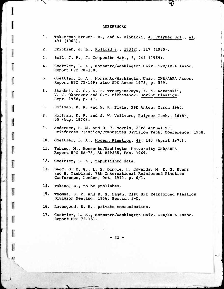
REFERENCES
1. Takserman-Krozer, R., and A. Ziabicki, J. Polymer Sei., Al, 491 (1963).
2. Ericksen, J. L., Kolloid Z., 173(2) , 117 (1960).
3. Bell, J. P., J. Composite Mat., 3, 244 (1969).
14. Goettler, L. A., Monsanto/Washington Univ. ONR/ARPA Assoc. Report HPC 70-130.
T5. Goettler, L. A., Monsanto/Washington Univ. ONR/ARPA Assoc. Report HPC 72-149; also SPE Antec 1973, p. 559.
6. Stankoi, G. G., E. B. Trostyanskaya, Y. N. Kazanskii, V. V. Okorokov and O.Y. Mikhasenok, Soviot Plastics, Sept. 1968, p. 47.
8. Hoffman, K. R. and J. W. Vellturo, Polymer Tech., 16(8), 50 (Aug. 1970).
7. Hoffman, K. R. and E. R. Fiala, SPE Antec, March 1966.
i 9. Andersen, H. M. and D. C. Morris, 23rd Annjal SPI
. Reinforced Plastics/Composites Division Tech. Conference, 1968
10. Goettler, L. A., Modern Plastics, 4£, 140 (April 1970).
11. Takano, M., Monsanto/Washington University ONR/ARPA Report HPC 68-73, AD 849285, Feb. 1969.
12. Goettler, L. A., unpublished data.
13. Bagg, G. E. G., L. E. Dingle, H. Edwards, M. E. N. Evans and H. Ziebland, 7th International Reinforced Plastics Conference, London, Oct. 1970, p. 6/1.
14. Takano, M., to be published.
15. Thomas, D. P. and R. S. Hagan, 21st SPI Reinforced Plastics Division Meeting, 1966, Section 3-C.
16. Lavengood, R. E., private communication.
_ 17. Goettler, L. A., Monsanto/Washington Univ. ONR/ARPA Assoc. Report HPC 72-151.
- 31 -
A.

I ^
r
LIST OF FTGURES
r
1. Channel geometry; D = 1.25"; d » .25, .375, or .50 inches.
2. Elongation rate effects in the determination of X; 40 v/o 1/4" CS308 fiberglass, a = 6°, d = 3/8".
3. Elongation rate variations in a 6° cone.
4. A comparison of actual anc extrapolated orientation angles to investigate a possible wall effect; 40 v/o 1/4" CSIOB fiberglass, a = 6°.
5. Elongation rate effects on the orientability parameter, X; 40 v/o 1/8" CS308A fiberglass, d = 3/8".
6. Rate effects on the predicted and measured rod stiffness; 40 v/o 1/8" CS308A fiberglass, d = 3/8" {A0/A = 11.1).
7. Relationship of rod stiffness to measured average polar angle, Bi, for various 1/8" fiberglass/epoxy transfer moldings (5).
8. Viscosity levels in the transfer moldings of 3/8" rods; 40 v/o 1/8" CS308A fiberglass, a = 6°.
9. Stiffness in 3/8" rods molded through a 90" entrance angle; 40 v/o 1/8" CS308A fiberglass.
10. Ultimate tensile strength in 3/8" rods molded through a 90° entrance angle; 40 v/o 1/8" CS308A fiberglass.
11. Stiffness in 1/4" molded rods; A0/A = 25.0, a = 6°, 40 v/o 1/8" CS308A fiberglass.
12. Stiffness in 1/2" molded rods; A0/A = 6.25, a = 6°, 40 v/o 1/8" CS308A fiberglass.
13. Orientability parameter, X, for longer 1/4" fibers, 47 v/o 1/4" CS308, a = 6°, d = 3/8".
14. Tensile properties of 1/2" rods molded from 1/4" fibers; a = 6°, 41 v/o 1/4" CS308A.
15. Orientation parameter and molded rod stiffness for milled glass fiber; 44 v/o 1/32" OCF Type 701L, a = 6°, A0/A = 11.1 (3/8" rod).
X •■.
- 32 -
_^ i ii >Tk ■

I
i I I
v1 V "V
^
16. Typical cross-section of a molding of .5 mil dia. glass fibers in epoxy.
17. Grains in a non-compacted molding compound flowing into an empty mold cavity.
18. Oscillation in the axial orientation profile in the cone;
a = 22-1/2°, d = 3/8", 40 v/o 1/8" fiberglass;
: e,, = 6.7 sec"^; b: e,, = 19.4 sec a
19. Oscillations in the axial orientation profile extending into the rod; a = 90°, d = 3/8", Q = 28.4 in3/min; 40 v/o 1/8" fiberglass.
20. Increase in X with smoothness of flow near the cone exit; a = 22-1/2°, 40 v/o 1/8" fiberglass, d = 3/8",
e,, = 19.4 sec
- 33 -
.*> i i fclLi

"*r •»-»^a«
^
LIST OF TABLES
I , 1. Limiting and average elongation rates in conical channels.
2. Agreement of rod stiffness for 3/8" moldings made at high 1 flow rate through a 90° entrance with predictions from X
f3. Variation of stiffness with rod diameter with a 90° entrance; 40 v/o 1/8" CS308A fiberglass.
4. Discrepancy between attained orientation and that predicted from X values.
5. Comparison of measured mechanical properties with those based on X values.
6. Effect of bundle aspect ratio.
7. Summary of tensile properties of molded composite rods.
8. Comparison of methods for aligning fibers.
D I
r n ii D R B 0
\
i - i i •"'fc- ^fe^^i
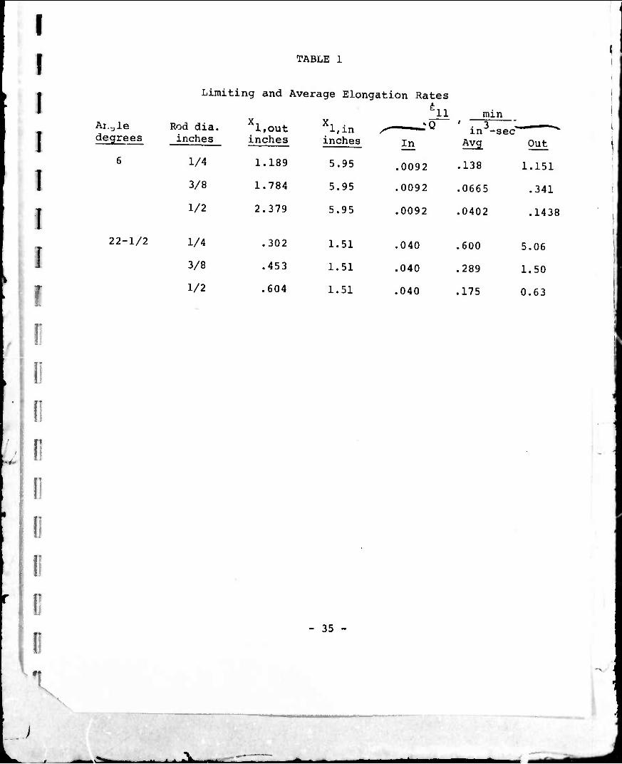
TABLE 1
'
Limiting and Average Elongation Rates äii min
Ai.^le degrees
Rod dia. inches
X, liOUt
inches
X, , l,in
inches In ' in3- Avg
•sec ~^ Out
6 1/4 1.189 5.95 .0092 .138 1.151
3/8 1.784 5.95 .0092 .0665 .341
1/2 2.379 5.95 .0092 .0402 .1438
22-1/2 1/4 .302 1.51 .040 .600 5.06
3/8 .453 1.51 .040 .289 1.50
1/2 .604 1.51 .040 .175 0.63
i
I: 0 !
r r r r V
- 35 -
.\^a . ^ ^.W- —
r
r
I I I" r
i i; D
n r i; D \
TABLE 2
Agreement of rod stiffness for 3/8" diameter molding made at high flow rate through a 90° entrance with predictions from X '
i | ,„-6 E , X 10~ a E x 10 pred %
psi difference
Q ell
in /min sec
2.47 3.68
4.46 6.65
: i. i 35.9
)S1
2.52 2.65 +4.9
2.33 2.30 -1.3
1.90 2.00 +5.0
- 36 -
i
^SL. M^i
f
i 'W
TABLE 3 ■
Effect of Area Reduction Ratio when a = 90°
Rod Diameter inches
Q
inVmin
3.1
3.1
E + aM
x 10"6
psi
2.31 + .11
2.48
E E3/8„
x 10"6
psi 103 psi
1/4
3/8 -.17
23.2
12.6
3/8 (upper branch)
19.0 2.62 1 +.05
26.5
A0/A
25.
11.1
11.1
6.25 1/2 19.0 2.67 + .01 , 22.0
- 37 -
• i ^^
I I I I I I I I I
I r [
[
r
TABLE 4
Discrepancy of Attained Orientation from X-Prediction
a = 6° 1/8" JMCS308A Fiberglass
40 v/o
At e,,* At e.^ = 1. sec"
Ro<? »o Predicted Actual Predicted Actual B,, degrees Qll degrees W^, degrees < degrees
1/2 6.25 10.1 22.5 32.4 29.5
3/8 11.1 3.8 20.8 19.1 21.2
1/4 25. 0.9 22.2 8.4 25.7
; diameter A inches "A~ "1' —»'— "l» —*™- "i' -^— "l' ~~'3-
- 38 -
* A.
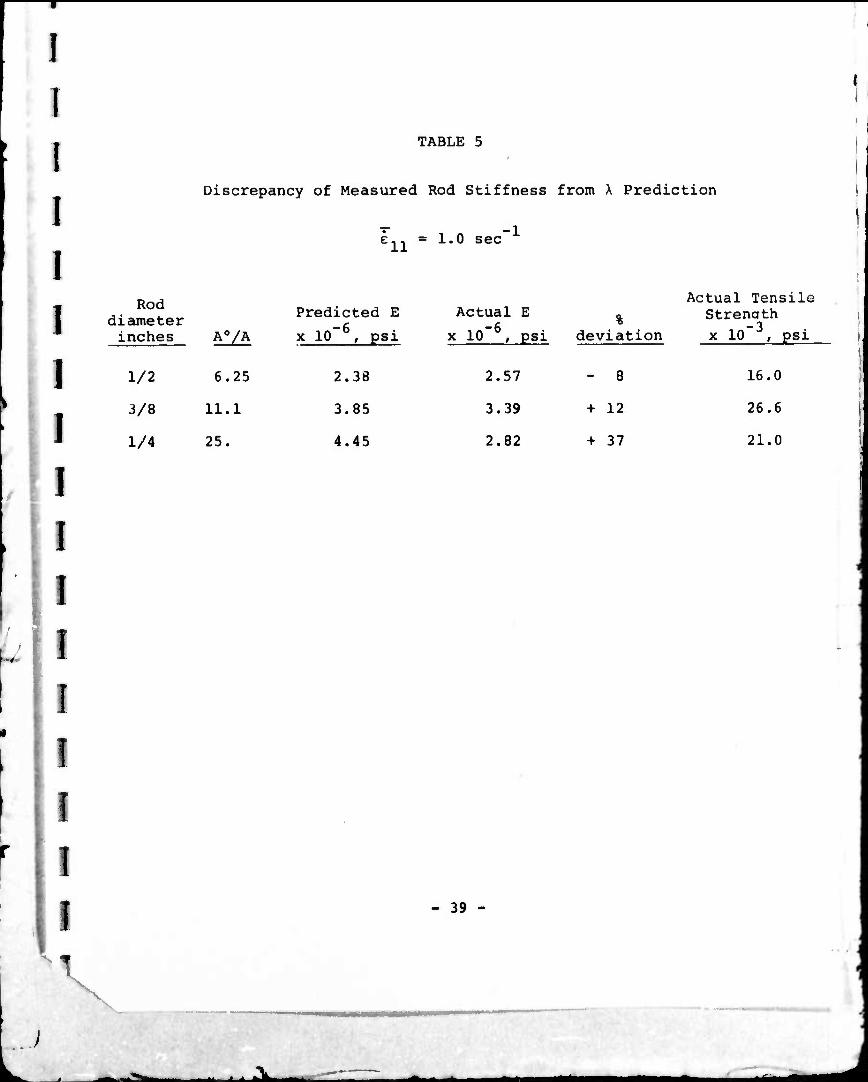
TABLE 5
Discrepancy of Measured Rod Stiffness from X Prediction
e,, = 1.0 sec -1
Rod diameter inches A0/A
Predicted E
x 10~ , psi
Actual E
x 10 , psi %
deviation
Actual Tensile Strenath x 10~ , psi
1/2 6.25 2.38 2.57 - 8 16.0
3/8 11.1 3.85 3.39 + 12 26.6
1/4 25. 4.45 2.82 + 37 21.0
V
- 39 -
■ - ^^ ■iM

T
!
I
I
I
I
I
I
I I! r
TABLE 6
Effect of Bundle Aspect Ratio
Rod diameter = 3/8" Fiber length = 1/4"
a = 6°
! # 0f Fiber -6 Jr-naih A™*««
!
Fiber filaments content E x 10 0 ^rengtn tensile designation per strand v/o psi x 10 , psi elongation, %
CS308 120 47 3.12 + 0.40 24.4 + 2.1 .98
CS308A 240 44 3.12 + 0.19 27.6 + 2.1 1.11 47* 3.32*"
| *corrected according to the volume fraction rule, assuming a fiber efficiency of 85%.
- 40 - »I \
.

I r [
[ i
r i i
u CQ <
: « * (N O O ro 1 • i 1 • I \ o\ oo
■H ^H
a v|
ro o X! ^(
•. C 43 0) ■P rH ■ VP •^f in rH ro tj GO 1 • • • •
U V cr« a\ r» r^ (NJ tl)
•H
iH rH r-t rH CN OJ
m CM
B ■ -H Tl H
i 01
1 : * * a H T o vo CTi •^T <D ■p \ • • • • | --i rH [^ r> rH CO r- to CM ro rH (N
I S ■M 0
a) rl
■P M 0) a 2
o
■rl
VT)
O
rH 3 T) 0 I a)
en C d)
(N
vl
00 o
in
(N
* * rg (M rH 1 i r^
(N
00
M
lO 00
<N
VO
(N
in
n
ft
n
fNJ
m
m
ro
vo oo
(N
oo
I !
r i
\ v
s o <
U I
Si -H
rH I
\'Ui
in (N
VO
(N 00 \ n
vo
<n
in CM
VO
<N
rH in rH (N
00
I o
o **
o >
* - 41 -
■
A.
I
I TABLE 8
Comparison of Methods for Aligning Short Fibers
Glass fibers in an epoxy matrix
1 Process Ref.
Fiber content
v/o
Average Fiber angle
6^, degrees
Controlled transfer molding
this work
40 19
!
I
Extrudate lay-up
(9) 40 57
20 20
Conventional (10) transfer molding
40 40-60
I Couette (11) flow
encapsulation + lay-up
57 7.
i: Elongated (12) 70 14. grain lay-up
E.R.D.E. process
(13) 57*
r \
♦graphite fiber, Modmor Type II
I
10° psi
3.9
Tensile strength 103 psi
3.5 5.0
1.5
5.7
7.0
14.
27.
33. 35.
7.
45.
39.
57. (ref. 16)
(ranged 43. to 73. with 1" gauge length)
r li - 42 -
V

I
[
(■
I
E
r
i
i
■ to X
i
n 0) a u c
O in
U 0
in CM
II
gg
■H
m
i i
ii i i »Tki
i:
!
r
I
I
I
1!
fl 1
I
I
I
I
I!
Nv
ro
o
0.4
0
-0.4
-0.8
-1.2
-1.6
/o/
Best fit to data
Least squares line
.6 8 IJO 1.2 1.4 1.6
log X
2. Elongation rate effects in the determination of X; 40 v/o 1/4" CS308 fiberglass, a = 6°, d = 3/8".
I
I;
I
i
n i
i
i
i
I
o
Vi;
j Distance from vertex,in. j
% \ ]/2 Channel diameter,in. i1^ 3. Elongation rate variations In a 6* cone. ,
-ki. J -i. ■ ^
i
i ■
[ 1
Jl
r
i:
i i i
a>
w 01
^-t 00 D»0 C ro « W
O C
■y \
CO <u\ •H > h Oo
ro
13 0) .» ■P ** a u O <"
(0 0) H ■p -i
T3 C 0) (T) rH
HI 3 4J U 1TJ
O
in in O • 0,0
« II ■
D< • ■H M
(0 K id ü H
a > D> E C M O -^ 0) ü J3
OH
c 0 n
•H
113
UD ^J- CM CM CVJ CM
00 U> ^- CM O
Sd9j6apt£^ pap.ipud
\
>-*»
^k i > >ik ^^^^MM ^te
I 1
\
I ■
i i; i
!
II 4 II
li
I 1 i 1)
o -|M
O CSJ
9> it ii
O •
o
o
o -led a>
tn
-*-
\'\U
C\J
«H oo <x> CVJ
GO
s-
2
s s. 2?
ja * n) oo ■U\ C ro 0)
•H I u 0 T3
0) • x: w ■P (0
C i-l o c^
H ui <u ■P x> O -H 0) <4-l
0) 00 O
0) n ■P w IO U U
s C oo 0\
•H rH «I fl o C > O
^-1 O W T
II I i ^k J
r
I I r r i
D M
4.5
40
3.5-
3.0
^ 2.5 o. i o
2.0
1.5
.0-
0.5
\ V
1\
J<ey. o a =6#
• a--22^2 — Predicted from X
( 9?'77*)
Fit to dato
J_ J L X L _L J_ .4X12 < 7 10 20
in .sec:' Rate effects on the predicted and measured rod stiffness; 40 v/o 1/8" CS308A fiberglass, d - 3/8" (A'/A = 11.1).
40
:v ^—
="S
I I I
'
I I 1 1 [
r r
r r r I
5.6
5.2
4.8
4.4
4.0
3.6
^
to CL
3.2
ID 1 O 2.8 X
ÜJ
2.4
2.0
1.6
1.2
.8
7. Relationship of rod stiffness to measured average polar angle, rl# for various 1/8" fibarglass/epoxy transfer moldings (5).
10 20 30 40 50 60 70 80 90
ft,DEGREES
^k.

"^r ^
I [ II i:
D i:
i IT
i (!
I li
r r r 1
c o c o s z^ ^ *~"
o — 51- o' -1 <T» r^ a> M M —
>- ^:> LÜ o
E O 2
"o ■| aoa<Dt>00 >s
CO
n§
o
<vi — O» 00
o
o
O cvj
ro
cvj
(O »o ^t: to
ro
UJ
1 : CD
0
g1 •H • •O o r-t VO 0 B II
u a 0)
VM k (0 (0 c n id id U rH
■P en H
0) 0) x: J3
IH C
•H < CO
WO rH n 0) CO > U 0)
rH : 00
>,\ +J p-l •H
■ 1*^11 •■ * I >TLl m*
^7 '—^^
I I I
^
T
r
r i
[
!
I 10
0
-i9
s
- t^w
^ E ro
CVJ O
- r»-
oo oo to OJ —»CVJ O '
isd' 01X3
V
u c id u 4J C u
o
n
ja • CP w 3 M 0 A U r-t x: v. ■u u
(U
Q) -H
^H 0 < E oo
o M n "a w o o u
- 00 oo\ S.H m
O C \
•H >
M O
| c •>
M-l 0) 1W ^ •H 01 ■M C W (0
s ^
i
H i
I [
I I r r i r r r r
00 CVJ CVJ CVJ
CVJ CVJ
o CVJ
CD co CVJ oo
o
o .c 0 (0 0 't) U 10 £ H
0) T3
0 e
^- —
ro
CVJ
u ID
XI
< 00 o
T3 ro 0 CO U U
c r CO CO W
C 0
> Xi •U O
c OJ .. M 0)
■P r-l to W
c u (d
-H Q) CO u c c o <0
■p kl ■p
0) c -P Q) ic Eo
•H O -U en iH D «
CC CVJ -JCVJ O "
!Sd£0l'Hi9N3dlS 31ISN3i 3iVWinn
J»

"^
f
^
: I
!
r
r [ I
!
I 1 i D
,1
!Sd'9-0lx3
o CO
I'MT
o
II
a
in
•a m 0 is
-o u <o a>
r-H H
< - CO ^r o >»« rH CO
U c •rl S
00
w •< 0) ß 0
«w > •iH ■P O
if i i aTki ^^^i
^N
I ^
I [
I r !"
r !
(
r r D I!
: O
in
I'MI
o VX3
II
c
in
IIV
o <
■ i U)
XS 0 u
h K t CO CM O \ro ■H W
U c
■r* S CO
«\ HI r-i 0 •!% c o
a ©
A ^ —

^s ^n^v—^ v
!
r
• 0 r (i
i K
-iO
- ^r
e\j
u
I O
IVü
o D> • C ■ O oo
rH \
O 11 IH
11 CVJ
o
u 0)
d) a e « - ^ 00 m o arn
w
■P o c\ 0) >
•H U I» o •
CVJ
o.
CVJ
.^v i^
■^ ¥
r r r r
11
!sOlx3 !Sd'v.oixg»6iJ9J|s 9|jSU9i
I s
— iQ I o o
E
w T3 O
- = <
(A «4-1 CJ
w ••/• 0) ^
n o <u\ a> o U rH
0) " rH O •H KO in C II 0) Ei O
■ I - Mi
I ^7
^
I
■
'
[
r r
i
r r
i i r
u o
(0 vo (0
8" U-i o IH ■H •■ ■U CQ (0 iH
O
?
O
to
I-VU
to I O -<
a 'S >< 0) H ■O H b.
88 -o-. C Ol
0) o ■P o u 3)\ e > = ia eo M -«r \ a —
o <u • ■H .Q -t ■P -H rH
■M II c in 0) 05 <
>-l (H e O o><
in


-^7 7
li ;
i "> -
i ^
r • Si [ P7
-
r I r
r S.
i; \
-
i: ^^
r r -
I" ■ i i • i i i
r r
o O o ID
o o o CVJ
2 c
-8
- ^
CsJ
ID C
5 C
•H
•H
O u
m
M rH 0) I
_ o
CO a>
- CD
- to
o ■U CO
0 >S •) ■4J r-l f-H c 0 o . il
H > r 0 L '
in ro V.
5 , c -a
c 0 H
■y (8
O 0) o
c
s r-l
1 <N
- CVJ
r 1
• - - Mi ^tm ^

^r ^^^^•^^
^
i
I [
1; r
11 r (i
i
D
60
5C
4Ü-
degrees 30
20
10
0
Distance From upstream end, inches 19. Oscillations in the axial orientation profile.fextending
into the rod; a = 90°, d = 3/8", Q ■ 28.4 in3/inin; 40 v/o 1/8" fiberglass.
I I
I
I !
I
.8r
.4
<& o
!
T
I I ^ r
r
r
V X o 0
0
ro 4 5-
■■
/ 5
-.8
-1.2 ^ / jo
/^
-1.6
1 o
-2.0 ~o f
1 1 1 1 1 J
\
L.J L
-.8 -.6 •4 -.2
log X
.4
20. Increase in X with smoothness of flow near the cone exit; a ■ 22-1/2°, 40 v/o 1/8" fiberglass, d = 3/8", ril "19.4 sec-1.
_:v